road power generation(lgme016) major
TRANSCRIPT
CHAPTER -1
INTRODUCTION
1 | P a g e

INTRODUCTION
1.1 The automotive industry
in India is one of the largest in the world and one of the fastest growing globally. India's
passenger car and commercial vehicle manufacturing industry is the seventh largest in the
world, with an annual production of more than 3.7 million units in 2010.We every day
mesh up with these vehicles give us headache .But this mesh up could be answer of new
type power generation
FIG NO . 1ROAD POWER GENERATION {RGP}
1.2 ROAD POWER GENERATION {RGP} this is one of the most recent power
generation concept. This device is engineered as a practical and useful alternative energy
technology for generating clean electricity from the millions of vehicles on our roadways.
Once fully optimized and installed, engineers anticipate that devices may be used to
augment or replace conventional electrical supplies for powering roadway signs, street
and building lights, storage systems for back-up and emergency power, and other
electronics, appliances, and even devices used in homes and businesses.
This device converts the kinetic energy of the vehicles into electric energy. This
is done by moving plate installed on the road, this plate take the stroke motion of the
2 | P a g e
vehicles and convert it to the rotary motion by crank mechanism and it generates the
electricity
1.3 Objective To build a mechanism which convert friction by vehicles on the road into stroke motion
and this stroke motion converted to rotary motion by one direction freewheel this rotate
motor via pulley and will generate electricity.
1.4 Working This device works on principle of friction and conversion of translator motion to
rotary motion. There is sliding plate fixed on the road which is fixed by spring. It takes
the stroke motion of the vehicles (slides the plate) and hit the freewheel (for
unidirectional motion), this rotate the flywheel (mechanical capacitor) turn the generator
via pulley arrangement and hence motive power generates.
1.5 Features:-
1) The unit have minimum visual impact on their surrounding environment
2) An RPG emits no noise
3) The unit will have minimum cost of installation and maintenance
4) This unit could be located at the close proximity to service and poer grid
5) Possible answer for battery charging station
1.6 Conclusions:- Road Power Generation this is new type of unconventional source of energy. This
is a type of vibration harvesting. This uses lost energy of vehicle and converts kinetic
energy to electric energy.
Here syringes are used as a actuator at the joints to move the parts and gripper
Which in turn move through water pushed by another syringe connected at other end via
rubber tube. The later is connected by dc motor which pushes the plunger of the syringe
via nut-bolt motion mechanism. Motor is controlled by switches mounted on the board
3 | P a g e
CHAPTER –2
BLOCK DIAGRAM
4 | P a g e

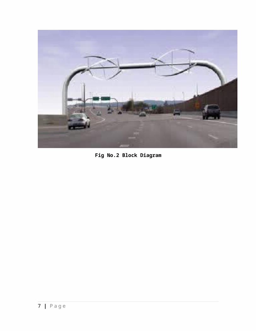
2.1 BLOCK DIAGRAM
Fig No.2 Block Diagram
5 | P a g e
CHAPTER -3
MATERIAL
6 | P a g e
3.1 MATERIAL DESCRIPTION
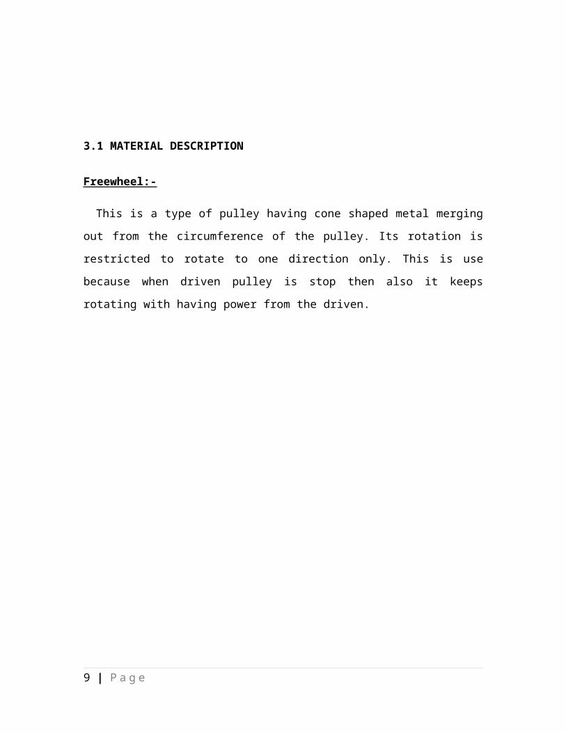
Freewheel:-
This is a type of pulley having cone shaped metal merging out from the circumference
of the pulley. Its rotation is restricted to rotate to one direction only. This is use because
when driven pulley is stop then also it keeps rotating with having power from the driven.
FIG NO.3 FREEWHEELS:-
3.2Bicycle Rim:- 7 | P a g e

The rim is commonly a metal extrusion that is butted into itself to form a hoop, though
may also be a structure of carbon fiber composite, and was historically made of wood.
Some wheels use both an aerodynamic carbon hoop bonded.
Fig no 4 Bicycle Rim:-3.3Helical spring:-
A Coil spring, also known as a helical spring, is a mechanical device, which is
typically used to store energy and subsequently release it, to absorb shock, or to maintain
a force between contacting surfaces. They are made of an elastic material formed into the
shape of a helix which returns to its natural length when unloaded.
Fig no 5
Bicycle
Rim
8 | P a g e
3.4 PULLEY:-
A pulley is a wheel on an axle that is designed to support movement of a cable or belt
along its circumference. Pulleys are used in a variety of ways to lift loads, apply forces,
and to transmit power. A pulley is also called a sheave or drum and may have
a groove between two flanges around its circumference. The drive element of a pulley
system can be a rope, cable, belt, or chain that runs over the pulley inside the groove.
3.5 WOODEN FRAME:-Timber framing and "post-and-beam" construction is a general term for building with
heavy timbers rather than "dimension lumber" such as 2"x4"s. Traditional timber framing
is the method of creating structures using heavy squared-off and carefully fitted and
joined timbers with joints secured by large wooden pegs (larger versions of the mortise
and tenon joints in furniture). It is commonplace in wooden buildings from the 19th
century and earlier. The method comes from making things out of logs and tree trunks
without modern high tech saws to cut lumber from the starting material stock. Using
axes, adzes and draw knives, hand powered auger drill bits (bit and brace), and laborious
woodworking, artisans or farmers could gradually assemble a building capable of bearing
heavy weight without excessive use of interior space given over to vertical support posts.
9 | P a g e
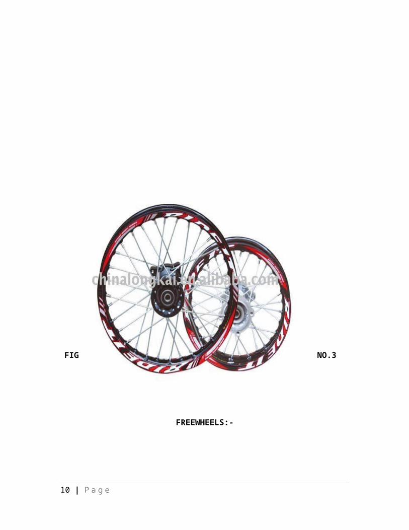
Fig.6 Wooden frame
Since this building method has been used for thousands of years in many parts of the
world there are many styles of historic framing. These styles are often categorized by the
type of foundation, walls, how and where the beams intersect, the use of curved timbers,
and the roof framing details. Three basic types of timber frames in English speaking
countries are the box frame, cruck frame, and aisled frame.
3.4 LDR:-
A photo
resistor
or light
dependent resistor (LDR) or photocell is a resistor whose resistance decreases with
increasing incident light intensity; in other words, it exhibits photoconductivity. A photo
resistor is made of a high resistance semiconductor. If light falling on the device is of
high enough frequency, photons absorbed by the semiconductor give bound electrons
10 | P a g e

enough energy to jump into the conduction band. The resulting free electron (and its hole
partner) conduct electricity, thereby lowering resistance.
Fig 6 LDR:-
A photoelectric device can be either intrinsic or extrinsic. An intrinsic semiconductor
has its own charge carriers and is not an efficient semiconductor, for example, silicon. In
intrinsic devices the only available electrons are in the valence band, and hence the
photon must have enough energy to excite the electron across the entire bandgap.
Extrinsic devices have impurities, also called dopants, added whose ground state energy
is closer to the conduction band; since the electrons do not have as far to jump, lower
energy photons (that is, longer wavelengths and lower frequencies) are sufficient to
trigger the device. If a sample of silicon has some of its atoms replaced by phosphorus
atoms (impurities), there will be extra electrons available for conduction. This is an
example of an extrinsic semiconductor.
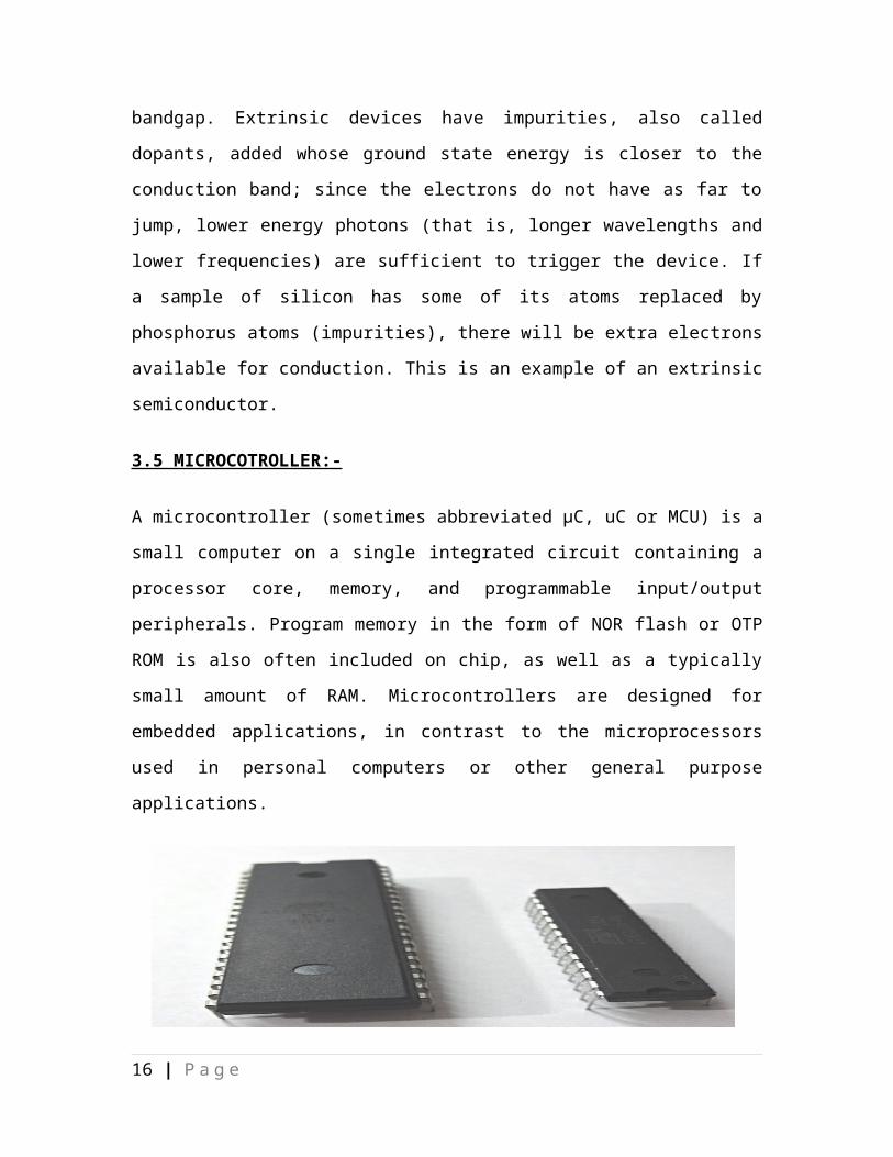
3.5 MICROCOTROLLER:-
A microcontroller (sometimes abbreviated µC, uC or MCU) is a small computer on a
single integrated circuit containing a processor core, memory, and programmable
input/output peripherals. Program memory in the form of NOR flash or OTP ROM is also
often included on chip, as well as a typically small amount of RAM. Microcontrollers are
designed for embedded applications, in contrast to the microprocessors used in personal
computers or other general purpose applications.
11 | P a g e

Microcontrollers are used in automatically controlled products and devices, such as
automobile engine control systems, implantable medical devices, remote controls, office
machines, appliances, power tools, toys and other embedded systems. By reducing the
size and cost compared to a design that uses a separate microprocessor, memory, and
input/output devices, microcontrollers make it economical to digitally control even more
devices and processes. Mixed signal microcontrollers are common, integrating analog
components needed to control non-digital electronic systems.
Some microcontrollers may use 4-bit words and operate at clock rate frequencies as
low as 4 kHz, for low power consumption (single-digit milliwatts or microwatts). They
will generally have the ability to retain functionality while waiting for an event such as a
button press or other interrupt; power consumption while sleeping (CPU clock and most
peripherals off) may be just nanowatts, making many of them well suited for long lasting
battery applications. Other microcontrollers may serve performance-critical roles, where
they may need to act more like a digital signal processor (DSP), with higher clock speeds
and power consumption.
L293D:-
An H bridge is an electronic circuit that enables a voltage to be applied across a load in
either direction. These circuits are often used in robotics and other applications to allow
DC motors to run forwards and backwards.[1]
Most DC-to-AC converters (power inverters), most AC/AC converters, the DC-to-DC
push–pull converter, most motor controllers, and many other kinds of power electronics
12 | P a g e

use H bridges. In particular, a bipolar stepper motor is almost invariably driven by a
motor controller containing two H bridges.
Fig 7L293D:-
CHAPTER -4
13 | P a g e

MATERIAL LIST
4.1 MATERIAL LIST:-
1) Freewheel
2) Dc Motor
3) Bicycle Rim
4) Helical spring
5) Pulley
6) Wooden frame
7) LDR
8) MICROCOTROLLER
9) L293D
14 | P a g e

CHAPTER -5
15 | P a g e
MATERIAL DESCRIPTION
MATERIAL DESCRIPTION
5.1 Freewheel:-
In mechanical or automotive engineering, a freewheel or overrunning clutch is a
device in a transmission that disengages the driveshaft from the driven shaft when the
driven shaft rotates faster than the driveshaft. An overdrive is sometimes mistakenly
called a freewheel, but is otherwise unrelated. The condition of a driven shaft spinning
16 | P a g e
faster than its driveshaft exists in most bicycles when the rider holds his or her feet still,
no longer pushing the pedals. In a fixed-gear bicycle, without a freewheel, the rear wheel
would drive the pedals around.
An analogous condition exists in an automobile with a manual transmission going
down hill or any situation where the driver takes his or her foot off the gas pedal, closing
the throttle; the wheels want to drive the engine, possibly at a higher RPM. In a two-
stroke engine this can be a catastrophic situation: as many two stroke engines depend on
a fuel/oil mixture for lubrication, a shortage of fuel to the engine would result in a
shortage of oil in the cylinders, and the pistons would seize after a very short time
causing extensive engine damage. Saab used a freewheel system in their two-stroke
models for this reason and maintained it in the Saab 96 V4 and early Saab 99 for better
fuel efficiency.
5.2 DC Motor
DC motor is an electric motor that runs on direct current (DC) electricity. DC motors
were used to run machinery, often eliminating the need for a local steam engine or
internal combustion engine. DC motors can operate directly from rechargeable batteries,
providing the motive power. Modern DC motors are nearly always operated in
conjunction with power electronic devices.
17 | P a g e

Fig 8 DC Motor
This is a type of pulley having cone shaped metal merging out from the circumference of
the pulley. Its rotation is restricted to rotate to one direction only. This is use because
when driven pulley is stop then also it keeps rotating with having power from the driven.
DC motors are configured in many types and sizes, including brush less, servo,
and gear motor types. A motor consists of a rotor and a permanent magnetic field
stator. The magnetic field is maintained using either permanent magnets or
electromagnetic windings. DC motors are most commonly used in
Variable speed and torque.
Motion and controls cover a wide range of components that in some way are used
to generate and/or control motion. Areas within this category include bearings and
bushings, clutches and brakes, controls and drives, drive components, encoders
and resolves, Integrated motion control, limit switches, linear actuators, linear and
rotary motion components, linear position sensing, motors (both AC and DC
motors), orientation position sensing, pneumatics and pneumatic components,
positioning stages, slides and guides, power transmission (mechanical), seals, slip
rings, solenoids, springs.
Motors are the devices that provide the actual speed and torque in a drive system.
This family includes AC motor types (single and multiphase motors, universal,
servo motors, induction, synchronous, and gear motor) and DC motors (brush
less, servo motor, and gear motor) as well as linear, stepper and air motors, and
motor contactors and starters.
18 | P a g e

In any electric motor, operation is based on simple electromagnetism. A current-
carrying conductor generates a magnetic field; when this is then placed in an
external magnetic field, it will experience a force proportional to the current in the
conductor, and to the strength of the external magnetic field. As you are well
aware of from playing with magnets as a kid, opposite (North and South)
polarities attract, while like polarities (North and North, South and South) repel.
The internal configuration of a DC motor is designed to harness the magnetic
interaction between a current-carrying conductor and an external magnetic field to
generate rotational motion.
Let's start by looking at a simple 2-pole DC electric motor (here red represents a
magnet or winding with a "North" polarization, while green represents a magnet
or winding with a "South" polarization).
Fig 9 Let's start by looking at a simple 2-pole DC electric motor
Every DC motor has six basic parts -- axle, rotor (a.k.a., armature), stator,
commutator, field magnet(s), and brushes. In most common DC motors (and all
that Beamers will see), the external magnetic field is produced by high-strength
permanent magnets1. The stator is the stationary part of the motor -- this includes
the motor casing, as well as two or more permanent magnet pole pieces. The rotor
19 | P a g e
(together with the axle and attached commutator) rotates with respect to the stator.
The rotor consists of windings (generally on a core), the windings being
electrically connected to the commutator. The above diagram shows a common
motor layout -- with the rotor inside the stator (field) magnets.
The geometry of the brushes, commutator contacts, and rotor windings are such
that when power is applied, the polarities of the energized winding and the stator
magnet(s) are misaligned, and the rotor will rotate until it is almost aligned with
the stator's field magnets. As the rotor reaches alignment, the brushes move to the
next commutator contacts, and energize the next winding. Given our example
two-pole motor, the rotation reverses the direction of current through the rotor
winding, leading to a "flip" of the rotor's magnetic field, and driving it to continue
rotating.
In real life, though, DC motors will always have more than two poles (three is a
very common number). In particular, this avoids "dead spots" in the commutator.
You can imagine how with our example two-pole motor, if the rotor is exactly at
the middle of its rotation (perfectly aligned with the field magnets), it will get
"stuck" there. Meanwhile, with a two-pole motor, there is a moment where the
commutator shorts out the power supply (i.e., both brushes touch both
commutator contacts simultaneously). This would be bad for the power supply,
waste energy, and damage motor components as well.
Yet another disadvantage of such a simple motor is that it would exhibit a high
amount of torque” ripple" (the amount of torque it could produce is cyclic with
the position of the rotor).
20 | P a g e

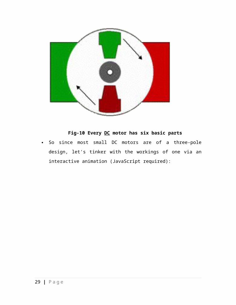
Fig-10 Every DC motor has six basic parts
So since most small DC motors are of a three-pole design, let's tinker with the
workings of one via an interactive animation (JavaScript required):
21 | P a g e

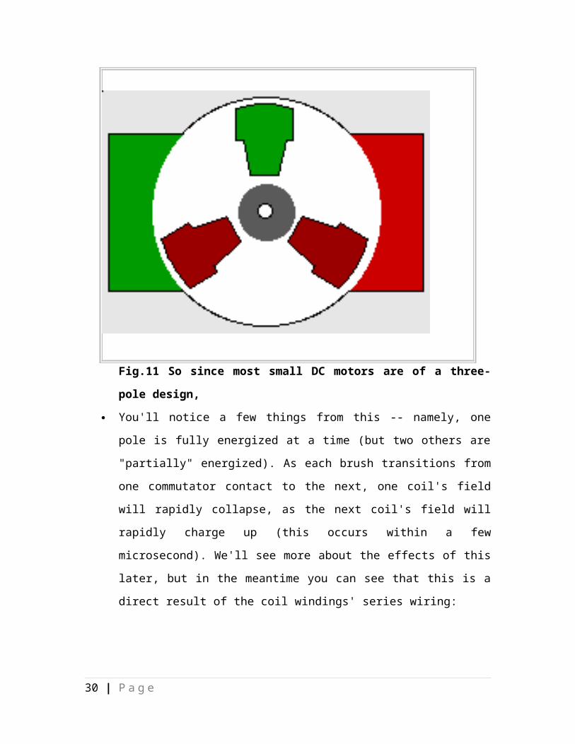
Fig.11 So since most small DC motors are of a three-pole design,
You'll notice a few things from this -- namely, one pole is fully energized at a
time (but two others are "partially" energized). As each brush transitions from one
commutator contact to the next, one coil's field will rapidly collapse, as the next
coil's field will rapidly charge up (this occurs within a few microsecond). We'll
see more about the effects of this later, but in the meantime you can see that this is
a direct result of the coil windings' series wiring:
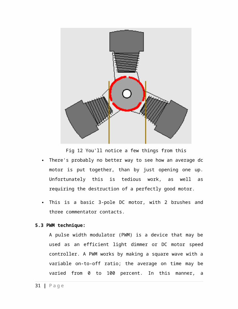
Fig 12 You'll notice a few things from this
There's probably no better way to see how an average dc motor is put together,
than by just opening one up. Unfortunately this is tedious work, as well as
requiring the destruction of a perfectly good motor.
This is a basic 3-pole DC motor, with 2 brushes and three commentator contacts.
5.3 PWM technique:
A pulse width modulator (PWM) is a device that may be used as an efficient light
dimmer or DC motor speed controller. A PWM works by making a square wave
22 | P a g e

with a variable on-to-off ratio; the average on time may be varied from 0 to 100
percent. In this manner, a variable amount of power is transferred to the load. The
main advantage of a PWM circuit over a resistive power controller is the
efficiency, at a 50% level, the PWM will use about 50% of full power, almost all
of which is transferred to the load, a resistive controller at 50% load power would
consume about 71% of full power, 50% of the power goes to the load and the
other 21% is wasted heating the series resistor. Load efficiency is almost always a
critical factor in solar powered and other alternative energy systems. One
additional advantage of pulse width modulation is that the pulses reach the full
supply voltage and will produce more torque in a motor by being able to
overcome the internal motor resistances more easily. Finally, in a PWM circuits,
common small potentiometers may be used to control a wide variety of loads
whereas large and expensive high power variable resistors are needed for resistive
controllers.
Pulse width modulation consists of three signals, which are modulated by a
square wave. The duty cycle or high time is proportional to the amplitude of the
square wave. The effective average voltage over one cycle is the duty cycle times
the peak-to-peak voltage. Thus, the average voltage follows a square wave. In
fact, this method depends on the motor inductance to integrate out the PWM
frequency.
A very simply off line motor drive can be built using a TRIAC and a control IC.
This circuit can control the speed of a universal motor. A universal motor is a
series wound DC motor. The circuit uses phase angle control to vary the effective
motor voltage.
A micro controller can also be used to control a triac. A PNP of transistor may be
used to drive the triac. As shown, the MCU ground is connected to the AC line.
The gate trigger current is lower if instead the MCU 5V supply is connected to the
AC line. The MCU must have some means of detecting zero crossing and a timer,
which can control the triac firing. A general-purpose timer with one input capture
and one output compare makes an ideal phase angle control.
23 | P a g e

5.4 MECHANICS
The simplest freewheel device consists of two saw-toothed, spring-loaded discs pressing
against each other with the toothed sides together, somewhat like a ratchet. Rotating in
one direction, the saw teeth of the drive disc lock with the teeth of the driven disc,
making it rotate at the same speed. If the drive disc slows down or stops rotating, the
teeth of the driven disc slip over the drive disc teeth and continue rotating, producing a
characteristic clicking sound proportionate to the speed difference of the driven gear
relative to that of the (slower) driving gear.
A more sophisticated and rugged design has spring-loaded steel rollers inside a driven
cylinder. Rotating in one direction, the rollers lock with the cylinder making it rotate in
unison. Rotating slower, or in the other direction, the steel rollers just slip inside the
cylinder.
Most bicycle freewheels use an internally step-toothed drum with two or more spring-
loaded, hardened steel pawls to transmit the load. More pawls help spread the wear and
give greater reliability although, unless the device is made to tolerances not normally
found in bicycle components, simultaneous engagement of more than two pawls is rarely
achieved.
5.5 BENEFITS
By its nature, a freewheel mechanism acts as an automatic clutch, making it possible to
change gears in a manual gearbox, either up- or downshifting, without depressing the
clutch pedal, limiting the use of the manual clutch to starting from standstill or stopping.
The Saab freewheel can be engaged or disengaged by the driver by pulling or pushing a
lever. This will lock or unlock the main shaft with the freewheel hub.
A freewheel also produces slightly better fuel economy on carbureted engines (without
fuel turn-off on engine brake) and less wear on the manual clutch, but leads to more wear
on the brakes as there is no longer any ability to perform engine braking. This may make
freewheel transmissions dangerous for use on trucks and automobiles driven in
24 | P a g e

mountainous regions, as prolonged and continuous application of brakes to limit vehicle
speed soon leads to brake-system overheating followed shortly by total failure.
5.6 USESAgricultural equipment
In agricultural equipment an overrunning clutch is typically used on hay balers and other
equipment with a high inertial load, particularly when used in conjunction with a tractor
without a live power take-off (PTO). Without a live PTO, a high inertial load can cause
the tractor to continue to move forward even when the foot clutch is depressed, creating
an unsafe condition. By disconnecting the load from the PTO under these conditions, the
overrunning clutch improves safety. Similarly, many unpowered 'push' cylinder
lawnmowers use a freewheel to drive the blades: these are geared or chain-driven to
rotate at high speed and the freewheel prevents their momentum being transferred in the
reverse direction through the drive when the machine is halted.
Engine starters
A freewheel assembly is also widely used on engine starters as a kind of protective
device. Starter motors usually need to spin at 3,000 RPM to get the engine to turn over.
When the key is turned to the start position for any amount of time after the engine has
already turned over, the starter can not spin fast enough to keep up with the flywheel.
Because of the extreme gear ratio between starter gear and flywheel (about 15 or 20:1) it
would spin the starter armature at dangerously high speeds, causing an explosion when
the centripetal force acting on the copper coils wound in the armature can no longer resist
the outward force acting on them. In starters without the freewheel or overrun clutch this
would be a major problem because, with the flywheel spinning at about 1,000 RPM at
idle, the starter, if engaged with the flywheel, would be forced to spin between 15,000
and 20,000 RPM. Once the engine has turned over and is running, the overrun clutch will
release the starter from the flywheel and prevent the gears from re-meshing (as in an
accidental turning of the ignition key) while the engine is running. A freewheel clutch is
25 | P a g e

now used in many motorcycles with an electric starter motor. It is used as a replacement
for the Bendix drive used on most auto starters because it reduces the electrical needs of
the starting system.
5.6 VEHICLE TRANSMISSIONS
In addition to the automotive uses listed above (i.e. in two-stroke-engine vehicles and
early four-stroke Saabs), freewheels were used in some luxury or up-market conventional
cars (such as Rovers and Cords) from the 1930s into the 1960s. The freewheel meant that
the engine returned to its idle speed on the overrun, thus greatly reducing noise from both
the engine and gearbox. The mechanism could usually be locked to provide engine
braking if needed. A freewheel was also used in the original Land Rover vehicle from
1948 to 1951. The freewheel controlled drive from the gearbox to the front axle, which
disengaged on the overrun. This allowed the vehicle to have a permanent 4 wheel drive
system by avoiding 'wind-up' forces in the transmission. This system worked, but
produced unpredictable handling, especially in slippery conditions or when towing, and
was replaced by a conventional selectable 4WD system.
Other car makers fitted a freewheel between engine and gearbox as a form of automatic
clutch. Once the driver released the throttle and the vehicle was on the overrun the
freewheel would disengage and a gearchange could be made without the use of the clutch
pedal. This feature appeared mainly on large, luxury cars which often had heavy clutches
and gearboxes without synchromesh as the freewheel permitted a smoother and quieter
change. Citroën combined a freewheel and a centrifugal clutch to make the so-called
'TraffiClutch' where the car could be started, stopped and the lower gears be changed
without using the clutch pedal. This was an option on Citroën 2CVs and its derivatives
and, as the name implied, was marketed as a benefit for driving in congested urban areas.
A common use of freewheeling mechanisms is in automatic transmissions. For instance
traditional, hydraulic General Motors transmissions such as the Turbo-Hydramatic 400
provide freewheeling in all gears lower than the selected gear. E.g., if the gear selector on
a three-speed transmission is labelled 'drive'(3)-'super'(2)-'low'(1) and the driver has
26 | P a g e

selected 'super', the transmission will freewheel if first gear is engaged, but not in second
or third gears; if in 'drive' it will freewheel in first or second; finally, if in low, it will not
freewheel in any gear. This allows the driver to select a lower range to achieve engine
braking at various speeds, for instance when descending steep hills.
5.7 BICYCLES
In the older style of bicycle, where the freewheel mechanism is included in the gear
assembly, the system is called a freewheel, whereas the newer style, in which the
freewheel mechanism is in the hub, is called a freehub.
5.8 HELICOPTERS
Freewheels are also used in rotorcraft. As a bicycle's wheels need to be able to rotate
faster than the pedals, so do a rotorcraft's blades need to be able to spin faster than its
drive engines. This is especially important in the event of an engine failure where a
freewheel in the main transmission allows the main and tail rotor systems to continue to
spin independent of the drive system. This provides for continued flight control and an
autorotation landing.
5.9 BICYCLE RIM:-
A bicycle wheel is a wheel, most commonly a wire wheel, designed for bicycle. A pair
is often called a wheelset, especially in the context of ready built "off the shelf"
performance-oriented wheels.Bicycle wheels are typically designed to fit into the frame
and fork via dropouts, and hold The rim is commonly a metal extrusion that is butted into
itself to form a hoop, though may also be a structure of carbon fiber composite, and was
historically made of wood. Some wheels use both an aerodynamic carbon hoop bonded.
5.10 Hub
A hub is the center part of a bicycle wheel. It consists of an axle, bearings and a hub
shell. The hub shell typically has two machined metal flanges to which spokes can be
27 | P a g e
attached. Hub shells can be one-piece with press-in cartridge or free bearings or, in the
case of older designs, the flanges may be affixed to a separate hub shell.
5.11Axle
The axle is attached to dropouts on the fork or the frame. The axle can attach using a
Quick release - a lever and skewer that pass through a hollow axle designed to
allow for installation and removal of the wheel without any tools (found on most
modern road bikes and some mountain bikes).
Nut - the axle is threaded and protrudes past the sides of the fork/frame. (often
found on track, fixed gear, single speed, BMX and inexpensive bikes)
bolt - the axle has a hole with threads cut into it and a bolt can be screwed into
those threads. (found on some single speed hubs, Cannondale Lefty hubs)
Thru axle - a long axle, typically 20 mm (110 mm width), [they can be 9 mm
(100.33 mm width) in diameter for durability], onto which the fork/frame clamps
(found on most mountain bike forks).
Female axle - hollow center axle, typically 14, 17, or 20 mm in diameter made of
chromoly and aluminum, with two bolts thread into on either side.This design can
be much stronger than traditional axles, which are commonly only 8 mm, 9 mm,
9.5 mm, or 10 mm in diameter.(found on higher end BMX hubs and some
mountain bike hubs)
Modern bicycles have adopted standard axle spacing: the hubs of front wheels are
generally 100 mm wide fork spacing, road wheels with freehubs generally have a
130 mm wide rear wheel hub. Mountain bikes have adopted a 135 mm rear hub
width,which allows clearance to mount a brake disc on the hub or to decrease the wheel
dish for a more durable wheel.Freeride and downhill are available with 150 mm spacing.
28 | P a g e
5.12 Bearings
The bearings allow the hub shell (and the rest of the wheel parts) to rotate freely
about the axle. Most bicycle hubs use steel or ceramic ball bearings. Older designs used
"cup and cone", whereas some modern wheels use pre-assembled "cartridge" bearings. A
"cup and cone" hub contains loose balls that contact an adjustable 'cone' that is screwed
onto the axle and a 'race' that is pressed permanently into the hub shell. Both surfaces are
smooth to allow the bearings to roll with little friction. This type of hub can be easily
disassembled for lubrication, but it must be adjusted correctly; incorrect adjustment can
lead to premature wear or failure. In a "cartridge bearing" hub, the bearings are contained
in a cartridge that is shaped like a hollow cylinder where the inner surface rotates with
respect to the outer surface by the use of ball bearings. The manufacturing tolerances, as
well as seal quality, can be significantly superior to loose ball bearings. The cartridge is
pressed into the hub shell and the axle rests against the inner race of the cartridge. The
cartridge bearing itself is generally not serviceable or adjustable; instead the entire
cartridge bearing is replaced in case of wear or failure.
5.13 Hub shell and flanges
The hub shell is the part of the hub to which the spokes (or disc structure) attach.
The hub shell of a spoked wheel generally has two flanges extending radially outward
from the axle. Although they superficially appear so, the flanges should not be plane, but
are actually canted inwards in the direction of the rim to reduce stress on the spoke
elbows. Each flange has holes or slots to which spokes are affixed. Some wheels (like the
Full Speed Ahead RD-800) have an additional flange in the center of the hub. Others
(like the some from Bontrager and Zipp) do not have a noticeable flange. The spokes still
attach to the edge of the hub but not through visible holes. Other wheels (like those from
Velomax/Easton) have a threaded hub shell that the spokes thread into. On traditionally-
spoked wheels, flange spacing effects the lateral stiffness of the wheel, with wider being
stiffer, and flange diameter effects the torsional stiffness of the wheel and the number of
spoke holes that the hub can accept, with larger diameter being stiffer and accepting more
holes.Asymmetrical flange diameters, tried to mitigate the adverse effects of
29 | P a g e
asymmetrical spacing and dish necessary on rear wheels with many sprockets, have also
been with modest benefits.
5.14 Hub brakes
Some hubs have attachments for disc brakes or form an integral part of drum
brakes.
Rear wheel of 1960s Bootie Folding Cycle with Sturmey-Archer drum brake
Disc brakes - a disc brake comprises circular plate or disc attached to the hub
which is squeezed between brake pads mounted within a caliper that is fixed to
one side of the wheel forks. The brake disc can be attached in a variety of ways
using bolts or a central locking ring.
Drum brakes - a drum brake has two brake shoes that expand out into the inside of
the hub shell. Rear mounted drum brakes are often used on tandems to
supplement the rear rim brake and give additional stopping power.
Coaster brake - coaster brakes are a particular type of drum brake which is
actuated by a backward pressure applied to the pedals. The mechanism is
contained inside the bicycle wheel hub shell.
5.15 Gears
The rear hub has one or more methods for attaching a gear to it.
Freehub - The mechanism that allows the rider to coast is built into the hub.
Splines on the freehub body allow a single sprocket or, more commonly, a
cassette containing several sprockets to be slid on. A lock ring then holds the
cog(s) in place. This is the case for most modern bicycles.
Freewheel - The mechanism that allows the rider to coast is not part of the hub, it
is contained in a separate freewheel body. The hub has threads that allow the
freewheel body to be screwed on, and the freewheel body has threads and/or
splines for fitting sprockets, or in the case of most single speed freewheels an
integral sprocket. This style of hub was used before the freehub became practical.
30 | P a g e
Track sprocket - There is no mechanism that allows the rider to coast. There are
two sets of threads on the hub shell. The threads are in opposite directions. The
inner (clockwise) set of threads is for a track sprocket and the outer (counter-
clockwise) set is for a reverse threaded lock ring. The reverse threads on the lock
ring keep the sprocket from unscrewing from the hub, which is otherwise possible
when slowing down.
Flip-flop hub - Both sides of the hub are threaded, allowing the wheel to be
removed and reversed in order to change which gear is used. Depending on the
style of threads, may be used with either a single speed freewheel or a track
sprocket.
Internal geared hub - the mechanism to provide multiple gear-ratios is contained
inside the shell of the hub. Many bicycles with three-speed internally geared hubs
were built in the last century. This is an extremely robust design, although much
heavier than more modern designs of multi-gear-ratio arrangements. Modern hubs
are available from three-speed to 14 speeds or a continuously variable
transmission hub, in the case of the NuVinci.
5. 16 Rim
Westwood rim as fitted to vintage roadster bicycles with rod/ stirrup brakes, today being
used in contemporary “drum brake” traditional utility bicycles Endrick Rim as fitted to
sports bicycles from the 1930s, 40s and 50s, forerunner of modern day rim brakes Rims
for tubular tires, referred to "sprint rims" in Britain The rim is commonly a metal
extrusion that is butted into itself to form a hoop, though may also be a structure of
carbon fiber composite, and was historically made of wood. Some wheels use both an
aerodynamic carbon hoop bonded to an aluminum rim on which to mount conventional
bicycle tires. Metallic bicycle rims are now normally made of aluminium alloy, although
until the 1980s most bicycle rims - with the exception of those used on racing bicycles -
were made of steel and thermoplastic.
Rims designed for use with rim brakes provide a smooth parallel braking surface, while
rims meant for use with disc brakes or hub brakes sometimes lack this surface. The
Westwood pattern rim was one of the first rim designs, and rod-actuated brakes, which
31 | P a g e
press against the inside surface of the rim were designed for this rim. These rims cannot
be used with caliper rim brakes. The cross-section of a rim can have a wide range of
geometry, each optimized for particular performance goals. Aerodynamics, mass and
inertia, stiffness, durability, tubeless tire compatibility, brake compatibility, and cost are
all considerations. If the part of the cross-section of the rim is hollow where the spokes
attached, as in the Sprint rim pictured, it is described as box-section or double-wall to
distinguish it from single-wall rims such as the Westwood rim pictured.The double wall
can make the rim stiffer. Triple-wall rims have additional reinforcement inside the box-
section. Aluminum rims are often reinforced with either single eyelets or double eyelets
to distribute the stress of the spoke. A single eyelet reinforces the spoke hole much like a
hollow rivet. A double eyelet is a cup that is riveted into both walls of a double-walled
rim.
5.17 Clincher rims
Most bicycle rims are "clincher" rims for use with clincher tires. These tires have a wire
or aramid (Kevlar or Twaron) fiber bead that interlocks with flanges in the rim. A
separate airtight inner tube enclosed by the rim supports the tire carcass and maintains the
bead lock. If the inner part of the rim where the inner tube fits has spoke holes, they must
be covered by a rim tape or strip, usually rubber, cloth, or tough plastic, to protect the
inner tube.
An advantage of this system is that the inner tube can be easily accessed in the
case of a leak to be patched or replaced.
The ISO 5775-2 standard defines designations for bicycle rims. It distinguishes between
1. Straight-side (SS) rims
2. Crochet-type (C) rims
3. Hooked-bead (HB) rims
32 | P a g e

Traditional clincher rims were straight-sided. Various "hook" (also called "crochet")
designs emerged in the 1970s to hold the bead of the tire in place, allowing high (6–
10 bar, 80–150 psi) air pressure.
5.18Tubular or sew-up rims
Some rims are designed for tubular tyres which are torus shaped and attached to
the rim with adhesive. The rim provides a shallow circular outer cross section in which
the tire lies instead of flanges on which tire beads seat.
5.19Tubeless
A tubeless tire system requires an airtight rim — capable of being sealed at the
valve stem, spoke holes (if they go all the way through the rim) and the tire bead seat —
and a compatible tire. Universal System Tubeless (UST), originally developed by Mavic,
Michelin and Hutchinson for mountain bikes is the most common system of tubeless
tires/rims for bicycles.The main benefit of tubeless tires is the ability to use low air
pressure for better traction without getting pinch flats because there is no tube to pinch
between the rim and an obstacle. Some cyclists have avoided the price premium for a
tubeless system by sealing the spoke holes with a special rim strip and then sealing the
valve stem and bead seat with a latex sealer. However, tires not designed for tubeless
application do not have as robust a sidewall as those that are.
The drawbacks to tubeless tires are that they are notorious for being harder to
mount on the rim than clincher tires and that the cyclist must still carry a spare tube to
insert in case of a flat tire due to a puncture. French tire manufacturer Hutchinson has
introduced a tubeless wheel system, Road Tubeless, that shares many similarities to the
UST (Universal System Tubeless) that was developed in conjunction with Mavic and
Michelin. Road Tubeless rims, like UST rims, have no spoke holes protruding to the air
chamber of the rim. The flange of the Road Tubeless rim is similar to the hook bead of a
standard clincher rim but is contoured to very close tolerances to interlock with a Road
Tubeless tire, creating an airtight seal between tire and rim. This system eliminates the
need for a rim strip and inner tube. Increasingly common are tubeless tires conforming to
33 | P a g e
the UST (Universal System Tubeless) standard pioneered by French wheel manufacturer
Mavic in conjunction with tire manufacturers Hutchinson and Michelin.
5.20 Spokes
The rim is connected to the hub by several spokes under tension. Original bicycle
wheels used wooden spokes that could be loaded only in compression, modern bicycle
wheels almost exclusively use spokes that can only be loaded in tension. There are a few
companies making wheels with spokes that are used in both compression and tension.
One end of each spoke is threaded for a specialized nut, called a nipple, which is used to
connect the spoke to the rim and adjust the tension in the spoke. This is normally at the
rim end. The hub end normally has a 90 degree bend to pass through the spoke hole in the
hub, and a head so it does not slip through the hole.
Double-butted spokes have reduced thickness over the center section and are lighter,
more elastic, and more aerodynamic than spokes of uniform thickness. Single-butted
spokes are thicker at the hub and then taper to a thinner section all the way to the threads
at the rim.Triple-butted spokes also exist and are thickest at the hub, thinner at the
threaded end, and thinnest in the middle. Apart from tubeless wheels, which do not need
them, tubed bicycle wheels require rim tapes or strips, a flexible but tough liner strip
(usually rubber or woven nylon or similar material) attached to the inner circumference
of the wheel to cover the ends of the nipples. Otherwise, the nipple ends wear a hole in
the tube causing a flat tire.
5.22 Cross section
Spokes are usually circular in cross-section, but high-performance wheels may
use spokes of flat or oval cross-section, also known as bladed, to reduce aerodynamic
drag. Some spokes are hollow tubes.
34 | P a g e
5.23 Material
The spokes on the vast majority of modern bicycle wheels are steel or stainless
steel. Stainless steel spokes are favored by most manufacturers and riders for their
durability, stiffness, damage tolerance, and ease of maintenance. Spokes are also
available in titanium, aluminum, or carbon fiber.
5.24 Number of spokes
Conventional metallic bicycle wheels for single rider bikes commonly have 28, 32
or 36 spokes, while wheels on tandems have as many as 40 or 48 spokes to support the
weight of an additional rider. BMX bikes commonly have 36 or 48 spoke wheels.
Lowrider bicycles may have as many as 144 spokes per wheel. Wheels with fewer spokes
have an aerodynamic advantage, as the aerodynamic drag from the spokes is reduced. On
the other hand, the reduced number of spokes results in a larger section of the rim being
unsupported, necessitating stronger and often heavier rims. Some wheel designs also
locate the spokes unequally into the rim, which requires a stiff rim hoop and correct
tension of the spokes. Conventional wheels with spokes distributed evenly across the
circumference of the rim are considered more durable and forgiving to poor maintenance.
The more general trend in wheel design suggests technological advancement in rim
materials may result in further reduction in the number of spokes per wheel.
5.25 Lacing
Lacing is the process of threading spokes through holes in the hub and rim so that
they form a spoke pattern. While most manufacturers use the same lacing pattern on both
left and right sides of a wheel, it is becoming increasingly common to find specialty
wheels with different lacing patterns on each side. A spoke can connect the hub to the rim
in a radial fashion, which creates the lightest and most aerodynamic wheel.However, to
efficiently transfer torque from the hub to the rim, as with driven wheels or wheels with
drum or disc brakes, durability dictates that spokes be mounted at an angle to the hub
flange up to a "tangential lacing pattern" to achieve maximum torque capability (but
minimum vertical wheel stiffness). Names for various lacing patterns are commonly
35 | P a g e
referenced to the number of spokes that any one spoke crosses. Conventionally laced 36-
or 32-spoke wheels are most commonly built as a cross-3 or a cross-2, however other
cross-numbers are also possible. The angle at which the spoke interfaces the hub is not
solely determined by the cross-number; as spoke count and hub diameter will lead to
significantly different spoke angles. For all common tension-spoke wheels with crossed
spokes, a torque applied to the hub will result in one half of the spokes - called "leading
spokes" tensioned to drive the rim, while other half - "trailing spokes" are tensioned only
to counteract the leading spokes. When forward torque is applied (i.e., during
acceleration ), the trailing spokes experience a higher tension, while leading spokes are
relieved, thus forcing the rim to rotate. While braking, leading spokes tighten and trailing
spokes are relieved. The wheel can thus transfer the hub torque in either direction with
the least amount of change in spoke tension, allowing the wheel to stay true while torque
is applied.
5.26 Adjustment ("truing")
There are three aspects of wheel geometry which must be brought into adjustment in
order to true a wheel. "Lateral truing" refers to elimination of local deviations of the rim
to the left or right of center. "Vertical truing" refers to adjustments of local deviations
(known as hop) of the radius, the distance from the rim to the center of the hub. "Dish"
refers to the left-right centering of the plane of the rim between the lock nuts on the
outside ends of the axle. This plane is itself determined as an average of local deviations
in the lateral truing.For most rim-brake bicycles, the dish will be symmetrical on the front
wheel. However, on the rear wheel, because most bicycles accommodate a rear sprocket
(or group of them), the dishing will often be asymmetrical: it will be dished at a deeper
angle on the non-drive side than on the drive side.
5.27Nipples
At one end of each spoke is a specialized nut, called a nipple, which is used to
connect the spoke to the rim and adjust the tension in the spoke. The nipple is usually
located at the rim end of the spoke but on some wheels is at the hub end to move its
36 | P a g e
weight closer to the axis of the wheel, reducing the moment of inertia. Until recently there
were only two types of nipples: brass and aluminum (often referred to as "alloy"). Brass
nipples are heavier than aluminum, but they are more durable. Aluminium nipples save
weight, but they are less durable than brass and more likely to corrode. A nipple at the
rim of a wheel usually protrudes from the rim towards the center of the wheel, but in
racing wheels may be internal to the rim, offering a slight aerodynamic advantage.
A wheel can be formed in one piece from a material such as thermoplastic (glass-filled
nylon in this case), carbon fiber or aluminium alloy. Thermoplastic is commonly used for
inexpensive BMX wheels. They have a low maximum tire pressure of 45 psi (3bars or
atmospheres).Carbon fiber is typically used for high-end aerodynamic racing wheels.
5.28 Disc wheels
Disc wheels are designed to minimize aerodynamic drag. A full disc is usually
heavier than traditional spoke wheels, and can be difficult to handle when ridden with a
cross wind. For this reason, international cycling organizations often ban disc wheels or
limit their use to the rear wheel of a bicycle. However, international triathlon federations
were (and are still) less restrictive and is what led to the wheels' initial usage growth in
popularity in the 1980s. A disc wheel may simply be a fairing that clips onto a traditional,
spoke wheel, addressing the drag that the spokes generate by covering them; or the disc
can be integral to the wheel with no spokes inside. In the latter case carbon fiber is the
material of choice. A spoke wheel with a disc cover may not be legal under UCI Union
Cycliste Internationale rules because it is a non-structural fairing but are again acceptable
under ITU International Triathlon Union rules. A compromise that reduces weight and
improves cross wind performance has a small number (three or four) tension-
compression spokes molded integral to the rim – also typically carbon fiber.
5.29 Helical spring:-
37 | P a g e

A spring is an elastic object used to store mechanical energy. Springs are usually made
out of spring steel. Small springs can be wound from pre-hardened stock, while larger
ones are made from annealed steel and hardened after fabrication. Some non-ferrous
metals are also used including phosphor bronze and titanium for parts requiring corrosion
resistance and beryllium copper for springs carrying electrical current (because of its low
electrical resistance).
When a spring is compressed or stretched, the force it exerts is proportional to its change
in length. The rate or spring constant of a spring is the change in the force it exerts,
divided by the change in deflection of the spring. That is, it is the gradient of the force
versus deflection curve. An extension or compression spring has units of force divided by
distance, for example lbf/in or N/m. Torsion springs have units of force multiplied by
distance divided by angle, such as N·m/rad or ft·lbf/degree. The inverse of spring rate is
compliance, that is: if a spring has a rate of 10 N/mm, it has a compliance of 0.1 mm/N.
The stiffness (or rate) of springs in parallel is additive, as is the compliance of springs in
series.
Depending on the design and required operating environment, any material can be
used to construct a spring, so long as the material has the required combination of rigidity
and elasticity: technically, a wooden bow is a form of spring.A Coil spring, also known
as a helical spring, is a mechanical device, which is typically used to store energy and
subsequently release it, to absorb shock, or to maintain a force between contacting
surfaces. They are made of an elastic material formed into the shape of a helix which
returns to its natural length when unloaded.
5.30 Types
Springs can be classified depending on how the load force is applied to them:
Tension/Extension spring – the spring is designed to operate with a tension load,
so the spring stretches as the load is applied to it.
Compression spring – is designed to operate with a compression load, so the
spring gets shorter as the load is applied to it.
38 | P a g e

Torsion spring – unlike the above types in which the load is an axial force, the
load applied to a torsion spring is a torque or twisting force, and the end of the
spring rotates through an angle as the load is applied.
Constant spring - supported load will remain the same throughout deflection cycle
Variable spring - resistance of the coil to load varies during compression
They can also be classified based on their shape:
Coil spring – this type is made of a coil or helix of wire
Flat spring – this type is made of a flat or conical shaped piece of metal.
Machined spring – this type of spring is manufactured by machining bar stock
with a lathe and/or milling operation rather than coiling wire. Since it is
machined, the spring may incorporate features in addition to the elastic element.
Machined springs can be made in the typical load cases of compression/extension,
torsion, etc.
The most common types of spring are:
Cantilever spring – a spring which is fixed only at one end.
Coil spring or helical spring – a spring (made by winding a wire around a
cylinder) and the conical spring – these are types of torsion spring, because the
wire itself is twisted when the spring is compressed or stretched. These are in turn
of two types:
Compression springs are designed to become shorter when loaded. Their turns
(loops) are not touching in the unloaded position, and they need no attachment
points.
A volute spring is a compression spring in the form of a cone, designed so that
under compression the coils are not forced against each other, thus permitting
longer travel.
Tension or extension springs are designed to become longer under load. Their
turns (loops) are normally touching in the unloaded position, and they have a
hook, eye or some other means of attachment at each end.
39 | P a g e

Hairspring or balance spring – a delicate spiral torsion spring used in watches,
galvanometers, and places where electricity must be carried to partially rotating
devices such as steering wheels without hindering the rotation.
Leaf spring – a flat spring used in vehicle suspensions, electrical switches, and
bows.
V-spring – used in antique firearm mechanisms such as the wheellock, flintlock
and percussion cap locks.
5.31 Other types include:
Belleville washer or Belleville spring – a disc shaped spring commonly used to
apply tension to a bolt (and also in the initiation mechanism of pressure-activated
landmines).
Constant-force spring — a tightly rolled ribbon that exerts a nearly constant force
as it is unrolled.
Gas spring – a volume of gas which is compressed.
Ideal Spring – the notional spring used in physics: it has no weight, mass, or
damping losses.
Mainspring – a spiral ribbon shaped spring used as a power source in watches,
clocks, music boxes, windup toys, and mechanically powered flashlights
Negator spring – a thin metal band slightly concave in cross-section. When coiled
it adopts a flat cross-section but when unrolled it returns to its former curve, thus
producing a constant force throughout the displacement and negating any
tendency to re-wind. The commonest application is the retracting steel tape rule.
Progressive rate coil springs – A coil spring with a variable rate, usually achieved
by having unequal pitch so that as the spring is compressed one or more coils
rests against its neighbour.
Rubber band – a tension spring where energy is stored by stretching the material.
Spring washer – used to apply a constant tensile force along the axis of a fastener.
Torsion spring – any spring designed to be twisted rather than compressed or
extended. Used in torsion bar vehicle suspension systems.
Wave spring – a thin spring-washer into which waves have been pressed.
40 | P a g e

Pulley:-
A pulley is a wheel on an axle that is designed to support movement of a cable or belt
along its circumference.[1] Pulleys are used in a variety of ways to lift loads, apply forces,
and to transmit power. A pulley is also called a sheave or drum and may have a groove
between two flanges around its circumference. The drive element of a pulley system can
be a rope, cable, belt, or chain that runs over the pulley inside the groove. Hero of
Alexandria identified the pulley as one of six simple machines used to lift weights.[2]
Pulleys are assembled to form a block and tackle in order to provide mechanical
advantage to apply large forces. Pulleys are also assembled as part of belt and chain
drives in order to transmit power from one rotating shaft to another.A pulley is
a wheel on an axle that is designed to support movement of a cable or belt along its
circumference. Pulleys are used in a variety of ways to lift loads, apply forces, and to
transmit power. A pulley is also called a sheave or drum and may have a groove between
two flanges around its circumference. The drive element of a pulley system can be
a rope, cable, belt, or chain that runs over the pulley inside the groove.
A set of pulleys assembled so that they rotate independently on the same axle form a
block. Two blocks with a rope attached to one of the blocks and threaded through the two
sets of pulleys form a block and tackle. A block and tackle is assembled so one block is
attached to fixed mounting point and the other is attached to the moving load. The
mechanical advantage of the block and tackle is equal to the number of parts of the rope
that support the moving block.
In the diagram on the right the mechanical advantage of each of the block and tackle
assemblies shown is as follows:
Gun Tackle: 2
Luff Tackle: 3
Double Tackle: 4
Gyn Tackle: 5
Threefold purchase: 6
41 | P a g e

Wooden frame:-
Timber framing and "post-and-beam" construction is a general term for building
with heavy timbers rather than "dimension lumber" such as 2"x4"s. Traditional timber
framing is the method of creating structures using heavy squared-off and carefully
fitted and joined timbers with joints secured by large wooden pegs (larger versions of
the mortise and tenon joints in furniture). It is commonplace in wooden buildings from
the 19th century and earlier. The method comes from making things out of logs and
tree trunks without modern high tech saws to cut lumber from the starting material
stock. Using axes, adzes and draw knives, hand powered auger drill bits (bit and
brace), and laborious woodworking, artisans or farmers could gradually assemble a
building capable of bearing heavy weight without excessive use of interior space given
over to vertical support posts.
Since this building method has been used for thousands of years in many parts of
the world there are many styles of historic framing. These styles are often categorized
by the type of foundation, walls, how and where the beams intersect, the use of curved
timbers, and the roof framing details. Three basic types of timber frames in English
speaking countries are the box frame, cruck frame, and aisled frame.
LDR:-
A photo resistor or light dependent resistor (LDR) or photocell is a resistor whose
resistance decreases with increasing incident light intensity; in other words, it exhibits
photoconductivity. A photo resistor is made of a high resistance semiconductor. If light
falling on the device is of high enough frequency, photons absorbed by the
semiconductor give bound electrons enough energy to jump into the conduction band.
42 | P a g e

The resulting free electron (and its hole partner) conduct electricity, thereby lowering
resistance.
A photoelectric device can be either intrinsic or extrinsic. An intrinsic semiconductor
has its own charge carriers and is not an efficient semiconductor, for example, silicon. In
intrinsic devices the only available electrons are in the valence band, and hence the
photon must have enough energy to excite the electron across the entire bandgap.
Extrinsic devices have impurities, also called dopants, added whose ground state energy
is closer to the conduction band; since the electrons do not have as far to jump, lower
energy photons (that is, longer wavelengths and lower frequencies) are sufficient to
trigger the device. If a sample of silicon has some of its atoms replaced by phosphorus
atoms (impurities), there will be extra electrons available for conduction. This is an
example of an extrinsic semiconductor.
MICROCOTROLLER:-
A microcontroller (sometimes abbreviated µC, uC or MCU) is a small computer on a
single integrated circuit containing a processor core, memory, and programmable
input/output peripherals. Program memory in the form of NOR flash or OTP ROM is also
often included on chip, as well as a typically small amount of RAM. Microcontrollers are
designed for embedded applications, in contrast to the microprocessors used in personal
computers or other general purpose applications.
Microcontrollers are used in automatically controlled products and devices, such as
automobile engine control systems, implantable medical devices, remote controls, office
machines, appliances, power tools, toys and other embedded systems. By reducing the
size and cost compared to a design that uses a separate microprocessor, memory, and
input/output devices, microcontrollers make it economical to digitally control even more
devices and processes. Mixed signal microcontrollers are common, integrating analog
components needed to control non-digital electronic systems.
Some microcontrollers may use 4-bit words and operate at clock rate frequencies as
low as 4 kHz, for low power consumption (single-digit milliwatts or microwatts). They
43 | P a g e

will generally have the ability to retain functionality while waiting for an event such as a
button press or other interrupt; power consumption while sleeping (CPU clock and most
peripherals off) may be just nanowatts, making many of them well suited for long lasting
battery applications. Other microcontrollers may serve performance-critical roles, where
they may need to act more like a digital signal processor (DSP), with higher clock speeds
and power consumption.
L293D:-
An H bridge is an electronic circuit that enables a voltage to be applied across a load in
either direction. These circuits are often used in robotics and other applications to allow
DC motors to run forwards and backwards.
Most DC-to-AC converters (power inverters), most AC/AC converters, the DC-to-DC
push–pull converter, most motor controllers, and many other kinds of power electronics
use H bridges. In particular, a bipolar stepper motor is almost invariably driven by a
motor controller containing two H bridges.
44 | P a g e

CONSTRUCTION
The first bicycle wheels followed the traditions of carriage building: a wooden
hub, a fixed steel axle (the bearings were located in the fork ends), wooden spokes and a
shrink fitted iron tire. A typical modern wheel has a metal hub, wire tension spokes and a
metal or carbon fiber rim which holds a pneumatic rubber tire.
45 | P a g e
REFERENCES
Website:
Google.com
Philips Semiconductor
46 | P a g e