road di2 series general guide
TRANSCRIPT

(English) DM-RAGN010-00
Dealer’s ManualROAD MTB Trekking
City Touring/ Comfort Bike
URBAN SPORT E-BIKE
ROAD Di2 Series General
Guide
This manual is the ROAD Di2 Dealer's Manual General Guide.
It provides overall wiring diagrams and explanations about installation
workflow, etc.
For details on how to handle individual products (individual components),
refer to the dealer's manual for each product.
Dealer's manuals can be viewed at the following link:
https://si.shimano.com

2
ContentsContents ...................................................................................2
IMPORTANT NOTICE ..................................................................3
TO ENSURE SAFETY ...................................................................4
About this manual ...................................................................8
Booklet structure .....................................................................9
Workflow overview ...............................................................10
List of tools to be used ..........................................................12
Installation/removal ..............................................................13
Overall wiring diagram ........................................................................13 • Example wiring for wireless gear shifting ............................................................................ 14
• Example wiring for wired gear shifting ................................................................................ 15
Wiring diagram around the cockpit ....................................................16 • Example wiring for wireless gear shifting ............................................................................ 16
• Example wiring for wired gear shifting (1) ........................................................................... 17
• Example wiring for wired gear shifting (2) ........................................................................... 18
• Wiring diagram for time trial/triathlon handlebar type ...................................................... 18
• Wiring diagram around the battery ..................................................................................... 20
Pairing ...................................................................................................20
Connection and communication with devices ...................................21
Maintenance .........................................................................................21
Electric wires .........................................................................................21 • Supported products ................................................................................................................ 21
• Conversion adapter ................................................................................................................ 22
• Connecting / disconnecting electric wires ............................................................................. 22
• Insertion direction of the electric wires for internal use ..................................................... 27
• Finishing for internal wiring .................................................................................................. 28
Checking connections ..........................................................................30
Troubleshooting .....................................................................31
When a problem occurs .......................................................................31

3
IMPORTANT NOTICE
IMPORTANT NOTICE • This dealer's manual is intended primarily for use by professional bicycle mechanics.Users who are not professionally trained for bicycle assembly should not attempt to install the components themselves using the dealer's manuals.If any part of the information on the manual is unclear to you, do not proceed with the installation. Instead, contact your place of purchase or a distributor for assistance.
• Make sure to read all manuals included with each product.
• Do not disassemble or modify the product other than as stated in the information contained in this dealer's manual.
• All manuals and technical documents are accessible online at https://si.shimano.com.
• For consumers who do not have easy access to the internet, please contact a SHIMANO distributor or any of the SHIMANO offices to obtain a hardcopy of the User's Manual.
• Please observe the appropriate rules and regulations of the country, state or region in which you conduct your business as a dealer.
• The Bluetooth® word mark and logos are registered trademarks owned by the Bluetooth SIG, Inc. and any use of such marks by SHIMANO INC. is under license.Other trademarks and trade names are those of their respective owners.
• ANT and ANT+ are trademarks or registered trademarks of ANT Wireless.
For safety, be sure to read this dealer's manual thoroughly before use, and follow it for correct use.
The following instructions must be observed at all times in order to prevent personal injury
and physical damage to equipment and surroundings.
The instructions are classified according to the degree of danger or damage which may occur
if the product is used incorrectly.
DANGERFailure to follow the instructions will result in death or serious
injury.
WARNINGFailure to follow the instructions could result in death or
serious injury.
CAUTIONFailure to follow the instructions could cause personal injury or
physical damage to equipment and surroundings.

4
TO ENSURE SAFETY
TO ENSURE SAFETY WARNING
• Be sure to follow the instructions provided in the manuals when installing the product.Only use SHIMANO genuine parts. If a component or replacement part is incorrectly assembled or adjusted, it can lead to component failure and cause the rider to lose control and crash.
• Wear approved eye protection while performing maintenance tasks such as replacing components.
Be sure to also inform users of the following:
• Clean the chain with an appropriate chain cleaner regularly. Intervals between maintenance depend on the use and riding circumstances.
• Never use alkali-based or acid-based solvents such as rust cleaners. If those solvents are used the chain might break and cause serious injury.
• Check that the wheels are fastened securely before riding the bicycle. Otherwise, you may fall and be seriously injured.
• Check the chain for any damage (deformation or cracking), skipping, or other abnormalities such as unintended gear shifting. If any problems are found, consult your place of purchase or a distributor. The chain may break, and you may fall.
• Be careful not to let the hemming of your clothes get caught in the chain while riding. Otherwise, you may fall off the bicycle.
For installation to the bicycle and maintenance
• When operating the shift switch, be careful not to allow your fingers to be caught in the derailleur. The motor in the derailleur is powerful enough to be operated without stopping until the shifting position is reached, and may cause serious injury if your fingers interfere with the shifting motion.
NOTICE
Be sure to also inform users of the following:
• The connectors are small and waterproof, so do not connect and disconnect electric wires except when necessary. Doing so may impair the waterproofing.
• Be careful not to get water into the connection terminals of the E-TUBE ports.

5
TO ENSURE SAFETY
• The components are designed to be fully waterproofed to withstand wet weather riding conditions; however, do not deliberately place them into water.
• Do not clean the bicycle with a high-pressure washer. If water gets into any of the components, operating problems or rusting may result.
• Be sure to keep rotating the crank arm during gear shifting operations.
• Handle the components carefully, and avoid subjecting them to strong shock.
• Do not use the thinners or harsh solvents to clean the products. Such solvents may damage the surface. When cleaning the products, use a cloth moistened with a neutral detergent diluted with water.
• If gear shifting operation does not feel smooth, consult the place of purchase for assistance.
• Keep away from magnetic objects. If this is not observed, problems with operation may occur.When installing a product that uses a magnet, make sure the magnet is set in the specified location before installing the product.
• Contact the place of purchase for updates of the component software. The most up-to-date information is available on the SHIMANO website.
• Products are not guaranteed against natural wear and deterioration from normal use and aging.
• For maximum performance we highly recommend SHIMANO lubricants and maintenance products.
For installation to the bicycle and maintenance
• Be sure to attach dummy plugs to any unused E-TUBE ports.
• Be sure to use SHIMANO original tool TL-EW02/TL-EW300 to remove and install the electric wires.
• Contact SHIMANO INC. for information regarding the shipment of the battery charger to South Korea and Malaysia.
• Use a brake hose/outer casing which still has some length to spare even when the handlebars are turned all the way to either side. Furthermore, check that the dual control levers do not touch the bicycle frame when the handlebars are turned all the way.
• The clamp band, clamp screw and clamp nut are not compatible with other products. Be sure to always use the clamp band, clamp screw or clamp nut which is specific to each product.

6
TO ENSURE SAFETY
� Electric wire
• Secure the electric wires with a zip tie so that they do not interfere with the chainrings, sprockets or tires.
• Do not remove the wire holders which are attached to the internal type electric wires (EW-SD50-I/EW-SD300-I). The wire holders prevent the electric wires from moving inside the frame.
• When installing to the bicycle, do not forcibly bend the electric wire plug. It may result in a poor connection.
• When connecting electric wires, make sure that foreign matter does not get inside the plug or E-TUBE port. A connection with foreign matter present may result in a malfunction.
• If the plug is exposed during storage, transportation, or maintenance work, and there is a possibility of foreign matter getting inside, protect the plug with masking tape or a similar material.
• If you do not feel a click when connecting an electric wire, check that there is no foreign matter inside the plug or E-TUBE port. If foreign matter is present, use a blower to remove it. If the problem persists, replace the electric wire with a new one.
The actual product may differ from the illustration because this manual is intended mainly to explain the procedures for using the product.
For installation to the bicycle
� Notes on reinstalling and replacing components
• When the product is reassembled or replaced, it is automatically recognized by the system to allow operation according to the settings.
• If the component configuration changes or malfunction is observed, use the E-TUBE PROJECT software to update the firmware of each component to the latest version and perform a check again. Also make sure that the E-TUBE PROJECT software is the latest version. If the software is not the latest version, the component compatibility or the product functions may not be available.
� Connection and communication with PC
• PC linkage devices can be used to connect a PC to the bicycle (system or components), and E-TUBE PROJECT can be used to carry out tasks such as customizing single components or the whole system and updating their firmware.If your versions of E-TUBE PROJECT software and firmware for each component are not up to date, there could be problems operating the bicycle. Check the software version and update it to the latest one.

7
TO ENSURE SAFETY
PC linkage device E-TUBE PROJECT Firmware
BT-DN300 SM-PCE02 Version 5.0.0 or later Version 4.0.0 or later
� Connection and communication with smartphone or tablet
• E-TUBE PROJECT for smartphones/tablets can be used to carry out tasks such as updating firmware and customizing single components or the whole system, after connecting the bicycle (system or components) to a smartphone or tablet via Bluetooth® LE.
• Disconnect the Bluetooth LE connection when not using E-TUBE PROJECT for smartphones/tablets.Using the rear derailleur communication function without disconnecting the Bluetooth LE connection increases battery consumption.
About compatibility with E-TUBE
• Check the following website for information on compatibility with each component and functional limitations:(https://bike.shimano.com/e-tube/project.html)

8
About this manual
About this manualThis manual is the ROAD Di2 Dealer's Manual General Guide. It provides overall wiring diagrams and explanations about installation workflow, etc.
For details on how to handle individual products (individual components), refer to the dealer's manual for each product.
Dealer's manuals can be viewed at the following link:
https://si.shimano.com

9
Booklet structure
Booklet structureROAD Di2 series manuals are split among several booklets, as described below.
The latest manuals are available on our website (https://si.shimano.com).
Name Details
ROAD Di2 Dealer's Manual General
Guide (this manual)
The basic manual for ROAD Di2. It contains overall wiring
diagrams and explanations about installation workflow.
Front Derailleur (Di2) Dealer's ManualThis manual describes front derailleur installation,
adjustment, and maintenance.
Di2 Battery and Parts Dealer's Manual This manual describes Di2 battery and parts installation.
Hydraulic Disc Brake / Dual Control
Lever (Di2) Dealer's Manual
This manual describes hydraulic disc brake / dual control
lever / satellite shifter installation, adjustment, and
maintenance.
Dual Pivot Caliper Brake / Dual
Control Lever (Di2) Dealer's Manual
This manual describes dual pivot caliper brake / dual
control lever / satellite shifter installation, adjustment, and
maintenance.
Rear Derailleur (Di2) Dealer's Manual
This manual describes rear derailleur functions and
toggling of wired connection modes, as well as rear
derailleur installation, adjustment, and maintenance.
E-TUBE User's ManualThis manual describes wireless connections (wireless
pairing).

10
Workflow overview
Workflow overviewWe recommend the following workflow.
Preparation/confirmation
Installation
Adjustment
MaintenanceConnection and communication
with devices
Preparation/confirmation
Process Reference
Checking wiringOverall wiring diagram
Wiring diagram around the cockpit
Pairing
Wired connection (system pairing): Rear Derailleur Dealer's
Manual
Wireless connection (wireless pairing): E-TUBE PROJECT
User's Manual
Checking before securing Checking connections
Handling electric wires Electric wires
Installation
Process Reference
Installing the dual control levers Hydraulic Disc Brake / Dual Control Lever (Di2) Dealer's
Manual
Dual Pivot Caliper Brake / Dual Control Lever (Di2) Dealer's
ManualInstalling satellite shifters
Temporarily installing the front
derailleurFront Derailleur Dealer's Manual
Installing the rear derailleur Rear Derailleur Dealer's Manual
Installing the battery ROAD Di2 Battery and Parts Dealer's Manual
Installing the bottom bracket and
cranksFront Chainwheel Dealer's Manual
Securing the front derailleur Front Derailleur Dealer's Manual

11
Workflow overview
Process Reference
Installing the brake calipers Hydraulic Disc Brake / Dual Control Lever (Di2) Dealer's
Manual
Dual Pivot Caliper Brake / Dual Control Lever (Di2) Dealer's
ManualSecuring the dual control levers
Confirming the chain length /
installing the chainRear Derailleur Dealer's Manual, Chain Dealer's Manual
Adjustment
Process Reference
Adjusting the rear derailleur Rear Derailleur Dealer's Manual
Adjusting the front derailleur Front Derailleur Dealer's Manual
Adjusting the dual control levers
Hydraulic Disc Brake / Dual Control Lever (Di2) Dealer's
Manual
Dual Pivot Caliper Brake / Dual Control Lever Dealer's
Manual
Connection and communication with devices
Process Reference
Connection and communication with
devicesRear Derailleur Dealer's Manual
Maintenance
Process Reference
Maintenance Dealer's manual for individual components

12
List of tools to be used
List of tools to be usedThe following tools are needed for installation, adjustment, and maintenance purposes.
Tool
TL-EW02
TL-EW300

13
Installation/removal
Overall wiring diagram
Installation/removalDi2 systems compatible with wireless gear shifting differ from existing Di2 systems in the following ways:
• Di2 systems with wireless gear shifting do not require a conventional junction [A] or a separate wireless unit.
• Depending on the model, wireless gear shifting is possible without the need for wiring from around the handlebars to inside the frame.
• BT-DN300 has three E-TUBE ports.
• The rear derailleur has the functionality for battery charging, wireless connection with the dual control levers and external devices (Bluetooth® LE or ANT), and a function button to switch shift modes, access adjustment mode, etc.
Overall wiring diagramRoute the wires through the frame before installing each component.
The ST-R9270 and ST-R8170 are capable of connecting wirelessly to the derailleurs. Other models of dual control levers or satellite shifters must use wired connections.
NOTICE
• Complete wiring and check the connections before installing the bottom bracket. This is particularly important when you use a press-fit bottom bracket.
• Attach dummy plugs to any unused ports.

14
Installation/removal
Overall wiring diagram
Example wiring for wireless gear shifting
This is a wiring example showing pairing of the dual control levers and rear derailleur via a portable device. Refer to the user's manual for E-TUBE PROJECT for how to perform pairing.
(A)
(B)
Wireless gear shifting(to rear derailleur)
BT-DN300
Wireless gear shifting(to dual control levers)
TECH TIPS
• The rear derailleur can connect to external devices in the same way as previous wireless units. Refer to the rear derailleur dealer's manual for details.
Electric wire (EW-SD300-I)
(A) Battery to front derailleur (A) ≤ 1500 mm
(B) Battery to rear derailleur (B) ≤ 1700 mm

15
Installation/removal
Overall wiring diagram
Example wiring for wired gear shifting
The shifters and rear derailleur are connected by electric wires. This setup uses junction [B]. In this wiring example, the wires, excluding the wires around the cockpit, are routed through the inside of the frame.
Junction [B]: EW-JC304
(D)
(C)
(B)
(A)
BT-DN300
Electric wire (EW-SD300-I)
(A) Battery to front derailleur (A) ≤ 1500 mm
(B) Battery to rear derailleur (B) ≤ 1700 mm
(C) Battery to junction [B](C) + (D) ≤ 2200 mm
(D) Dual control levers to junction [B]

16
Installation/removal
Wiring diagram around the cockpit
Wiring diagram around the cockpit
Example wiring for wireless gear shifting
ST-R9270ST-R8170
ST-R9270ST-R8170
SW-RS801-SSW-RS801-T
SW-RS801-SSW-RS801-T
Port for satellite
shifter
Port for satellite shifter
E-TUBE port(for SD300)
E-TUBE port(for SD300)
Satellite shifter plug

17
Installation/removal
Wiring diagram around the cockpit
Example wiring for wired gear shifting (1)
ST-R9270ST-R9250ST-R8170ST-R8150
ST-R9270ST-R9250ST-R8170ST-R8150
SW-RS801-SSW-RS801-T To battery
E-TUBE plug (EW-SD300-I)
Satellite shifter plug
SW-RS801-SSW-RS801-T
EW-JC304
*The number of E-TUBE ports differs depending on the model.
E-TUBE port(for SD300) x 2*
E-TUBE port(for SD300) x 2*
Port for satellite
shifter
Port for satellite shifter

18
Installation/removal
Wiring diagram around the cockpit
Example wiring for wired gear shifting (2)
ST-R9250ST-R8150
ST-R9250ST-R8150
SW-RS801-SSW-RS801-T To battery
SW-RS801-SSW-RS801-T
E-TUBE plug (EW-SD300-I)
Satellite shifter plug
E-TUBE port(for SD300) x 2
E-TUBE port(for SD300) x 2
Port for satellite
shifter
Port for satellite shifter
Wiring diagram for time trial/triathlon handlebar type
Wiring in which the dual control levers and battery are connected by electric wires. For information on compatible time trial/triathlon components, refer to the E-TUBE compatibility table (https://bike.shimano.com/e-tube/project/compatibillity.html).
NOTICE
• The cockpit area only uses the EW-SD50-I electric wire. Do not connect junction [A] or a wireless unit.

19
Installation/removal
Wiring diagram around the cockpit
EW-SD300-IEW-SD50-I
EW-AD305
EW-JC130SM-JC41
SW-R9160 SW-R9160
To battery
ST-R9160ST-R9180ST-R8060
ST-R9160ST-R9180ST-R8060

20
Installation/removal
Pairing
Wiring diagram around the battery
For wireless connections, route wires as shown in the figure.
Front derailleur
Rear Derailleur
Electric wire: EW-SD300-I
BT-DN300
Dual control lever
PairingPairing is required after reinstalling or replacing the dual control levers or rear derailleur. Perform pairing with a wired or wireless connection. Wireless gear shifting requires the dual control levers to be paired with the rear derailleur.
For information on pairing with a wireless connection, refer to the user's manual for E-TUBE PROJECT. For information on pairing with a wired connection, refer to the dealer's manual for the rear derailleur (Di2).

21
Installation/removal
Connection and communication with devices
Connection and communication with devicesIt is possible to check the settings of each component by connecting the bicycle to a device. For details, refer to the Rear Derailleur Dealer's Manual.
MaintenanceRefer to the dealer's manuals for individual components for information on periodic maintenance.
Electric wiresBe sure to use the SHIMANO original tool to remove and insert electric wires.
There are two types of electric wire: the EW-SD300-I and the EW-SD50-I. The supported electric wire differs based on the component model. Check the component specifications on the SHIMANO product website in advance (https://productinfo.shimano.com/).
Supported products
The following products support each type of electric wire.
Product name Intended purpose EW-SD300-I type EW-SD50-I type
SHIMANO original
tool
Connecting / disconnecting
the electric wiresTL-EW300 TL-EW02
Dummy plug Plugging empty ports Y7HE30000 Y6VE15000
Cord clip
Binding the wiring and the
outer casing / brake hose
together
EW-CL300-S
(for shift outer casing)
EW-CL300-M
(for outer casing and
brake hose)
Y70H98040
Grommet
Installing to the wire
insertion hole of a frame
that supports internal
wiring
EW-GM300-S
EW-GM300-M
SM-GM01
SM-GM02
Junction [B]
Conjoining the wiring
inside and outside the
frame
EW-JC304
EW-JC302
SM-JC41
SM-JC40
EW-JC200
EW-JC130
Conversion adapterRefer to the “Conversion
adapter” section.EW-AD305 EW-AD305

22
Installation/removal
Electric wires
NOTICE
• When connecting and disconnecting electric wires, do not forcibly bend the plug part. It may result in a poor connection.
• The SHIMANO original tool used for installation/removal and the accessories used for wiring differ for the EW-SD300-I and EW-SD50-I. Be sure to use a compatible product.
• EW-CL300-S is marked with a groove in order to differentiate it from EW-CL300-M.
Differentiation groove
EW-CL300-M EW-CL300-S
Conversion adapter
A conversion adapter (EW-AD305) is required to connect the EW-SD50-I to a component with an E-TUBE port for the EW-SD300-I.
Electric wire (EW-SD300-I) Electric wire (EW-SD50-I)
Conversion adapter (EW-AD305)
Connecting / disconnecting electric wires
Be sure to use the SHIMANO original tool to remove and insert electric wires.
NOTICE
• When connecting and disconnecting electric wires, do not forcibly bend the plug part. It may result in a poor connection.
`Connecting the electric wire (EW-SD300-I)Connect the electric wire to the E-TUBE port.

23
Installation/removal
Electric wires
1. Set the plug of the electric wire to the TL-EW300.
If there is an alignment tab on the plug of the electric wire, check the shape of the E-TUBE port you are trying to connect to, and set it aligned with the alignment tab as shown in the figure.
Without alignment tab on plug
Groove
Guide
Groove
Guide
Alignment tab
With alignment tab on plug

24
Installation/removal
Electric wires
2. Insert the plug on the electric wire into the E-TUBE port.
Push it straight in until you feel it click into place.
E-TUBE port
Plug
TECH TIPS
• You can use the TL-EW300 as indicated in the figure to install the electric wire.
E-TUBE port
Groove
`Removing the electric wire (EW-SD300-I)
1. Remove the electric wire.
(1) Insert the TL-EW300 into the groove on the plug part of the electric wire.
25
Installation/removal
Electric wires
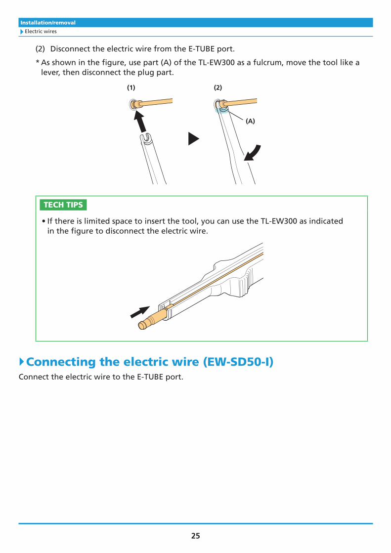
(2) Disconnect the electric wire from the E-TUBE port.
* As shown in the figure, use part (A) of the TL-EW300 as a fulcrum, move the tool like a lever, then disconnect the plug part.
(A)
(1) (2)
TECH TIPS
• If there is limited space to insert the tool, you can use the TL-EW300 as indicated in the figure to disconnect the electric wire.
`Connecting the electric wire (EW-SD50-I)Connect the electric wire to the E-TUBE port.

26
Installation/removal
Electric wires
1. Set the plug of the electric wire to the TL-EW02.
If there is an alignment tab on the plug of the electric wire, set it aligned with the groove on the SHIMANO original tool.
Without alignment tab on plug With alignment tab on plug
2. Insert the plug on the electric wire into the E-TUBE port.
Push it straight in until you feel it click into place.
E-TUBE port
Plug
`Removing the electric wire (EW-SD50-I)
1. Remove the electric wire.
(1) Insert the TL-EW02 into the groove on the plug of the electric wire.

27
Installation/removal
Electric wires
(2) Disconnect the electric wire from the E-TUBE port.
* As shown in the figure, use part (A) of the TL-EW02 as a fulcrum, move the tool like a lever, then disconnect the plug part. If there is limited space to insert the tool, lift the TL-EW02 straight up and disconnect the electric wire.
(1) (2)
(A)
NOTICE
• Do not repeatedly connect and disconnect the electric wire too often. The connector may become worn or deformed, and affect the waterproof function or connection function.
Insertion direction of the electric wires for internal use
Electric wires for internal use come with wire holders to prevent the electric wires from moving inside the frame. When passing an electric wire for internal use through the frame, insert in the direction shown in the figure.
Wire holder Frame wiring hole
NOTICE
• When passing an electric wire through the frame, handlebar, or other parts, protect the plug with masking tape or a similar material to prevent foreign matter from getting inside.

28
Installation/removal
Electric wires
TECH TIPS
• Insert the wire holder in the direction shown in the figure above. This will allow the wire holders to be removed more easily when pulling out the electric wire from the frame wiring hole it was inserted into.
Finishing for internal wiring
When routing the electric wire inside the frame, install a grommet to the wiring hole of the frame for protective purposes after passing the electric wire through the frame.
Example of installing to the chainstay (wiring to the rear derailleur)
Example of installing to the seat tube (wiring to the front derailleur)
TECH TIPS
• There are two types of grommets as shown in the figure. Use the correct one according to the shape of the wiring hole.
GM300-S
Circular wiring hole
GM300-M
Elliptical wiring hole
1. Install each component and connect the electric wire.
For details, refer to the dealer's manuals for individual components. Pass the electric wire through the inside of the frame as indicated in the wiring diagram, and connect each component.

29
Installation/removal
Electric wires
2. After installing and connecting all the components, perform the procedures in “Checking connections.”
3. Open the grommet from the center, and place it over the electric wire in the appropriate position.
Perform the procedure after determining the length of the electric wire to expose from the frame in advance.
Installation example to the down tube
Handlebar side
4. Install the grommet.
(1) Insert the grommet so that it hooks onto the wiring hole of the frame.
(2) Push in the grommet with your finger.
(1) (2)
TECH TIPS
• If the grommet is difficult to insert, spray it with isopropyl alcohol to aid installation.

30
Installation/removal
Checking connections
Checking connectionsAfter connecting the electric wires to all of the components, check the operation.
1. Check the connection for each component.
(1) Refer to the user's manual of the dual control lever to operate the shift switch and confirm the operation of the derailleurs.
(2) Refer to the user's manual for the rear derailleur to check the LED display for operation, etc.
(3) Connect to E-TUBE PROJECT and check that each component is displayed in E-TUBE PROJECT. For details, refer to the user's manual for E-TUBE PROJECT.
When there is a problem with a component connection:
Return to the installation procedure for each component, and check the electric wire connections and pairing.
2. After checking the connections, disconnect the electric wires from the battery and components.
WARNING
• Make sure to remove the electric wires from the battery and components when performing a procedure at a position near the front derailleur, such as installation and removal of the crankset and front derailleur or chain installation and length adjustment. If the front derailleur is accidentally triggered while performing a maintenance procedure, your fingers could get caught in the front derailleur and be injured.

31
Troubleshooting
When a problem occurs
TroubleshootingWhen a problem occursCheck the following information if you have a problem.
If the problem is not covered below or cannot be solved with the indicated method, contact a distributor.
Symptoms Causes / possibilities Remedies
Click cannot be felt when
connecting an electric wire.
Cannot fully connect a wire.
Is there foreign matter inside the
plug or E-TUBE port?
Check that there is no foreign
matter inside the plug or E-TUBE
port. If foreign matter is present,
use a blower to remove it. If the
problem persists, replace the
electric wire with a new one.

Please note: specifications are subject to change for improvement without notice. (English)
© May 2021 by SHIMANO INC. ITP