rnrg 80 meter xhd talltower™ installation manual ... · pdf filernrg 80 meter xhd...
TRANSCRIPT

RNRG 80 meter XHD TallTower™ Installation Manual & Specifications
For RNRG Tower Kits 4771, 4772, 4773, 4774, and 4990
& RNRG-NOW System Kits
4843, 4844, 4845, 4846 and 10472

80m_XHD_TallTower_Manual | Rev 20 | 14 November 2016 | [email protected] || 2
© Renewable NRG Systems 110 Riggs Road
Hinesburg VT 05461 USA Tel: 802-482-2255 Fax: 802-482-2272
[email protected] www.rnrgsystems.com
Specifications are subject to change without notice.

80m_XHD_TallTower_Manual | Rev 20 | 14 November 2016 | [email protected] || 3
Table of Contents
Chapter 1: Safety Considerations ...................................................................................................... 8
1.1 Warnings .................................................................................................................................... 8
1.2 SAFETY CONSIDERATIONS: ANSI Z535.5 ...................................................................................... 9
1.3 SAFETY CONSIDERATIONS FOR TOWER INSTALLATIONS IN AGRICULTURAL AREAS OR REMOTE AREAS WHERE LOW FLYING AIRCRAFT OPERATE ............................................................................. 12
1.4 Tower Obstruction Marking ....................................................................................................... 13
1.5 References ............................................................................................................................... 13
Chapter 2: Pre-Installation Guidelines ............................................................................................ 14
2.1 TallTower History ..................................................................................................................... 14
2.2 Construction and Assembly....................................................................................................... 14
2.3 Required Parts to Erect Tower System ...................................................................................... 14
2.4 Experience Required ................................................................................................................. 15
2.5 Tower Lift Crew ........................................................................................................................ 15
2.6 Using This Manual .................................................................................................................... 16
2.7 Tools ........................................................................................................................................ 16 2.7.1 Tools Supplied with Tower Kits ....................................................................................................... 16 2.7.2 Tools Supplied with Installation Toolkit #4832 ............................................................................... 16 2.7.3 Tools Required but not Supplied .................................................................................................... 16
2.8 Unpack Your Tower .................................................................................................................. 18 2.8.1 Description of the Envirocrate packaging ....................................................................................... 18 2.8.2 Tools required to unpack the Envirocrate ...................................................................................... 18 2.8.3 Envirocrate Access and Orientation................................................................................................ 19 2.8.4 Envirocrate Unpack Sequence – Very Important! .......................................................................... 19
2.9 Site Layout ............................................................................................................................... 23 2.9.1 Pre-installation Planning .................................................................................................................. 23 2.9.2 Soil Type and Anchors ..................................................................................................................... 23 Tip: Cellular Coverage .............................................................................................................................. 23

80m_XHD_TallTower_Manual | Rev 20 | 14 November 2016 | [email protected] || 4
2.10 Site Layout Map ...................................................................................................................... 24 2.10.1 Slopes Greater than +1.5°................................................................................................................ 24 2.10.2 Slopes Less than -2° ......................................................................................................................... 24
Chapter 3: Tower Components Assembly........................................................................................ 30
3.1 Assemble the Baseplate ............................................................................................................ 30
3.2 Assemble Cable from Baseplate to 8” Screw-in Anchor ............................................................. 36
3.3 Install the Anchors .................................................................................................................... 37
3.4 Tube Layout .............................................................................................................................. 38
3.5 Install the Tower Base Tube ....................................................................................................... 40
3.6 Attach the Lightning Spike ......................................................................................................... 46
3.7 Attach sensors and booms ........................................................................................................ 48
3.8 Spiral wrap your sensor cables .................................................................................................. 48
3.9 Attach the Guy Wires ................................................................................................................ 49 3.9.1 Organize and layout the lifters and guy wires ................................................................................... 49 3.9.2 Guy wire roll out sequence ................................................................................................................ 50 3.9.3 Shackle lifter wires to the guy rings................................................................................................... 50 3.9.4 Back Guy Wire Marking Distance From Guy Level ............................................................................ 51 3.9.5 Roll out guy wires .............................................................................................................................. 51 3.9.6 Secure guy wires to the anchors ....................................................................................................... 53
3.10 Ginpole Assembly ................................................................................................................... 54 3.10.1 Layout the ginpole tubes ................................................................................................................. 54 3.10.2 Attach the ginpole base tube to the baseplate ............................................................................... 54 3.10.3 Slide together the 10 tubes that comprise the ginpole................................................................... 55 3.10.4 Attach the ginpole jumper strut end-flanges ................................................................................... 57 3.10.5 Attach the turnbuckles to the end-flanges ...................................................................................... 58 3.10.6 Attach the ginpole jumper struts .................................................................................................... 59 3.10.7 Attach the ginpole jumper strut cables ........................................................................................... 61 3.10.8 Attach the ginpole top mounting hardware .................................................................................... 63 3.10.9 Attach the Lifter Wires & Front Guy Wires ..................................................................................... 65 3.10.10 Critical Installation Step: Attach the pulley blocks to the ginpole ................................................ 68 3.10.11 Configure the helper ginpole ......................................................................................................... 68 3.10.12 Setting up the winch and hydraulic power unit (HPU) .................................................................. 70 3.10.13 Anchor the winch........................................................................................................................... 74 3.10.14 Reeving the winch cable ................................................................................................................ 75 3.10.15 Critical Installation Step: Tensioning the ginpole jumper strut cables ......................................... 80
80m_XHD_TallTower_Manual | Rev 20 | 14 November 2016 | [email protected] || 5
Chapter 4: Installation Process ....................................................................................................... 82
4.1 Ginpole Tilt-Up ......................................................................................................................... 82 4.1.1 Confirm all guy wires, lifters and shackles are secure ........................................................................ 82 4.1.2 Lift the ginpole .................................................................................................................................... 82
4.2 Tower Tilt-Up ........................................................................................................................... 83 4.2.1 Understanding Guy Wire Tensioning While Raising TallTower (Do not raise the tower yet) ........... 83 4.2.2 Adjusting Guy Wires .......................................................................................................................... 84 4.2.3 Loosening Guy Wires ......................................................................................................................... 84 4.2.4 Tightening Guy Wires ........................................................................................................................ 85 4.2.5 Monitor the weather ......................................................................................................................... 85
4.3 Lifting the tower ....................................................................................................................... 86 4.3.1 Phase 1: Tower Lift from 0° to 60° ..................................................................................................... 86 4.3.2 Critical Installation Step: Permissible Deflection .............................................................................. 86 4.3.3 Phase 2: Tower Lift from 60° to 90° using the Back Stay Tensioning System ................................... 87
4.4 Attaching Front Guy Wires ........................................................................................................ 88
4.5 Plumb and Straighten Tower..................................................................................................... 88 4.5.1 Guy Tension Check ............................................................................................................................ 89
Critical Installation Step: Guy Tension Measurement Methods .............................................................. 90 4.5.1.1 Pulse Method ............................................................................................................................... 90 4.5.1.2 Tangent Intercept Method .......................................................................................................... 92
4.6 Transfer Lifters ......................................................................................................................... 95
4.7 Final Inspection and Maintenance ............................................................................................ 98
Chapter 5: Tower Lowering .......................................................................................................... 101
5.1 Tower Lowering Overview ....................................................................................................... 101 5.1.1 Critical Installation Step: Tensioning the ginpole jumper strut cables ........................................... 101 5.1.2 Critical Installation Procedure: Utilize the Back Stay Tensioning System....................................... 101 5.1.3 Phase 1: Tower Lowering from 90° to 60° (Max tension on back stay tensioning system = 150 lbf.) ................................................................................................................................................................... 101 5.1.3 Tower Lowering from 80° to 60° ..................................................................................................... 102 5.1.4 Phase 2: Tower Lowering from 60° to 0° ......................................................................................... 102
Appendix A: 80m XHD with Standard Footprint ............................................................................ 103 A.1 Tower Layout ................................................................................................................................... 103 A.2 Site Layout ....................................................................................................................................... 104
A.3 Tower Erection Forces ........................................................................................................................ 105 A.4 ANSI/TIA-222-G Compliance Limits, Maximum Anchor Loads, and Baseplate Loads ........................ 107
A.5 Code Compliance Curve – Imperial Units ........................................................................................ 108 A.6 Code Compliance Curve – SI Units ................................................................................................... 109

80m_XHD_TallTower_Manual | Rev 20 | 14 November 2016 | [email protected] || 6
A.7 Stamped Drawing ............................................................................................................................ 110 Stamped Drawing ................................................................................................................................... 111 A.8 Anchor Loads – Imperial Units ......................................................................................................... 112 A.9 Anchor Loads - SI Units .................................................................................................................... 113 A.10 Baseplate Loads – Imperial Units .................................................................................................. 114 A.11 Baseplate Loads – SI Units ............................................................................................................. 115
Appendix B: Anchoring Guidelines ................................................................................................ 117 B.1 Determine site soil and anchor type before you order your tower ................................................... 117 B.2 Anchor Choices and other considerations.......................................................................................... 117 B.3 Screw-In Anchor Description .............................................................................................................. 117 B.4 Rock Anchor Description .................................................................................................................... 119 B.5 Installing Screw-In Anchors ................................................................................................................. 119 B.6 Installing 8 inch diameter twin helix anchors ..................................................................................... 120 B.7 Installing Rock Anchors ....................................................................................................................... 122
Appendix C: Site Visit Procedures ................................................................................................. 123 C.1 Site Checklist........................................................................................................................................ 123
Appendix D: 80m XHD TallTower Painted Version ......................................................................... 124
Appendix E: RNRG 80m XHD TallTower Back Guywire Tensioner Assembly and Operating Instructions ................................................................................................................................... 125
E.1 Introduction ........................................................................................................................................ 125 E.2 Back Guywire Tensioner System Overview ........................................................................................ 125 E.3 Back Guywire Tensioner Assembly ..................................................................................................... 127 E.4 Tower Lift ............................................................................................................................................ 129
E.4.1 Phase 1: Tower Lift from 0° to 60° ................................................................................................ 130 E.4.2 Phase 2: Tower Lift from 60° to 90° .............................................................................................. 130 E.4.3 Lift-Cycle Instructions ................................................................................................................... 133 E.4.4 Attach the Front Guys .................................................................................................................... 135 E.4.5 Plumb and Straighten Tower ......................................................................................................... 135
E.5 Lowering the tower ............................................................................................................................ 136
Appendix F: 2.4 m (95”) Side Mount Boom Installation ................................................................. 137 F.1 Introduction ........................................................................................................................................ 137 F.2 Installation ........................................................................................................................................... 137
Appendix G: Aligning Wind Vanes ................................................................................................. 142 G.1 Introduction ....................................................................................................................................... 142 G.2 Magnetic Declination ......................................................................................................................... 142 G.3 Mounting and Aligning Wind Vanes ................................................................................................... 142 G.4 Using Data Analysis Software to Correct for Magnetic Declination .................................................. 145
Appendix H: ANSI/TIA-222-G Foundation Considerations .............................................................. 146 Baseplate Geometry (with ground surface area of 19.5 ft2 ) .................................................................. 146

80m_XHD_TallTower_Manual | Rev 20 | 14 November 2016 | [email protected] || 7
Appendix I: Goal Post Boom Mounting Instructions ....................................................................... 147 Introduction ............................................................................................................................................... 147 Tools .......................................................................................................................................................... 148 Step 1: Unpack boxes ................................................................................................................................ 148 Step 2: Assemble Goal Post Boom ............................................................................................................ 149
1) Lay the four pipes out in a flat area .............................................................................................. 149 2) Install clamps................................................................................................................................. 149 3) Set distance from cross bar bracket to cross bar bracket at 15 inches ........................................ 149 4) Feed sensor cables up through the bottom of the uprights ......................................................... 149 5) Mount the stubby tube ................................................................................................................. 150 6) Mount the Goal Post Boom on the tower .................................................................................... 150 7) Mount sensors on boom ............................................................................................................... 151 8) Attach visibility light ...................................................................................................................... 151
Index ............................................................................................................................................ 152

80m_XHD_TallTower_Manual | Rev 20 | 14 November 2016 | [email protected] || 8
Chapter 1: Safety Considerations
1.1 Warnings
ALWAYS DO THE FOLLOWING:
Only install or remove TallTowers using experienced installation crew members who are familiar
with all TallTower components and safe installation and removal procedures. Contact RNRG for
referral to qualified installers.
Always follow all instructions and warnings in the TallTower Installation Manual, as well as all
other technical information necessary for the safe installation in a specific location.
Always consult with appropriate professionals to determine soil type at the installation site and
then the most appropriate anchor system for use at that site. Follow all anchor manufacturers’
instructions.
Always stand to the side of any guy wire under tension so that you are not in the path of a guy
wire that breaks or comes loose.
Always consult with appropriate authorities (e.g., the Federal Aviation Administration, local
building or zoning departments, etc.) and surrounding land owners if a TallTower is being
installed in an agricultural area to determine installation and tower marking requirements so as
to minimize risk to low flying agricultural aircraft.
NEVER DO THE FOLLOWING:
Never begin an installation with an inexperienced or untrained installation crew.
Never allow installation crew members to commence work unless and until each crew member
has thoroughly read and understands the information contained in the TallTower Installation
Manual.
Never stand in a direct line with any guy wire under tension as it could cause serious injury or
death if it breaks or comes loose.
Never climb a TallTower.
Never erect a TallTower in an area where electrical power lines pose a hazard.
80m_XHD_TallTower_Manual | Rev 20 | 14 November 2016 | [email protected] || 9
Never allow unauthorized persons in the area where a TallTower is being installed.
Never begin or continue a TallTower installation during high winds.
Never begin or continue a TallTower installation during an electrical storm or when one is
imminent.
Never use parts for one TallTower to create a shorter TallTower; this cannot be done safely.
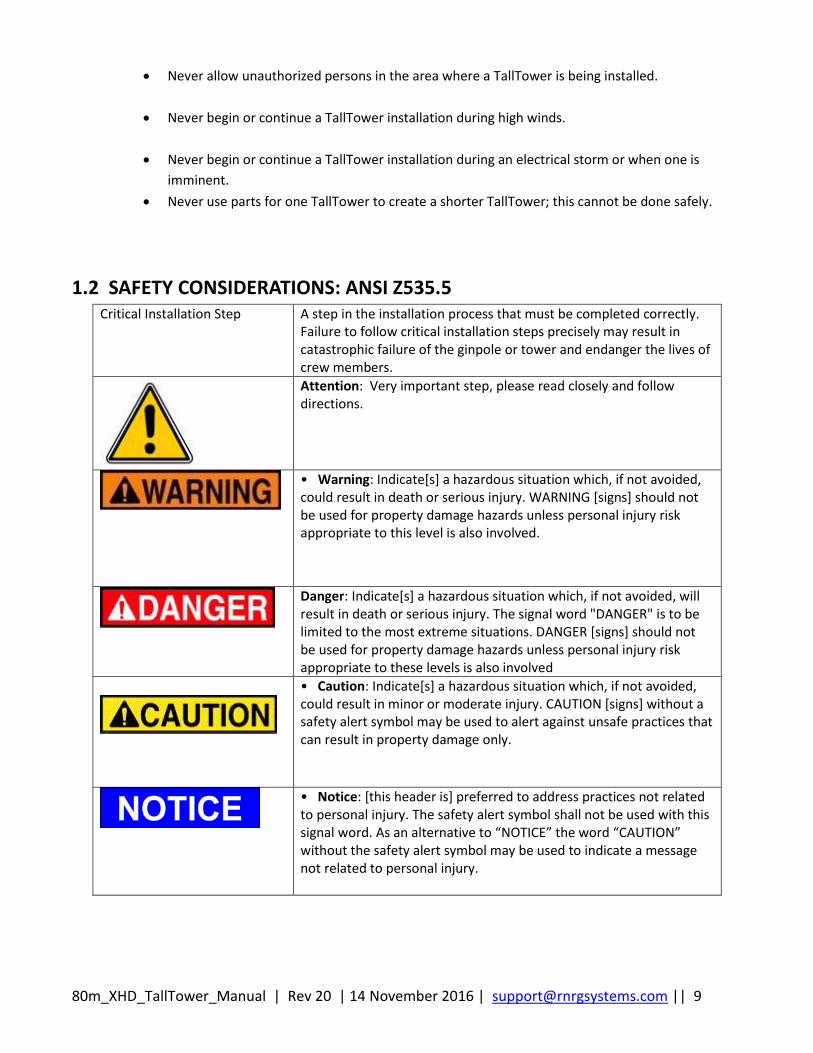
1.2 SAFETY CONSIDERATIONS: ANSI Z535.5 Critical Installation Step A step in the installation process that must be completed correctly.
Failure to follow critical installation steps precisely may result in catastrophic failure of the ginpole or tower and endanger the lives of crew members.
Attention: Very important step, please read closely and follow directions.
• Warning: Indicate[s] a hazardous situation which, if not avoided, could result in death or serious injury. WARNING [signs] should not be used for property damage hazards unless personal injury risk appropriate to this level is also involved.
Danger: Indicate[s] a hazardous situation which, if not avoided, will result in death or serious injury. The signal word "DANGER" is to be limited to the most extreme situations. DANGER [signs] should not be used for property damage hazards unless personal injury risk appropriate to these levels is also involved
• Caution: Indicate[s] a hazardous situation which, if not avoided, could result in minor or moderate injury. CAUTION [signs] without a safety alert symbol may be used to alert against unsafe practices that can result in property damage only.
• Notice: [this header is] preferred to address practices not related to personal injury. The safety alert symbol shall not be used with this signal word. As an alternative to “NOTICE” the word “CAUTION” without the safety alert symbol may be used to indicate a message not related to personal injury.
80m_XHD_TallTower_Manual | Rev 20 | 14 November 2016 | [email protected] || 10
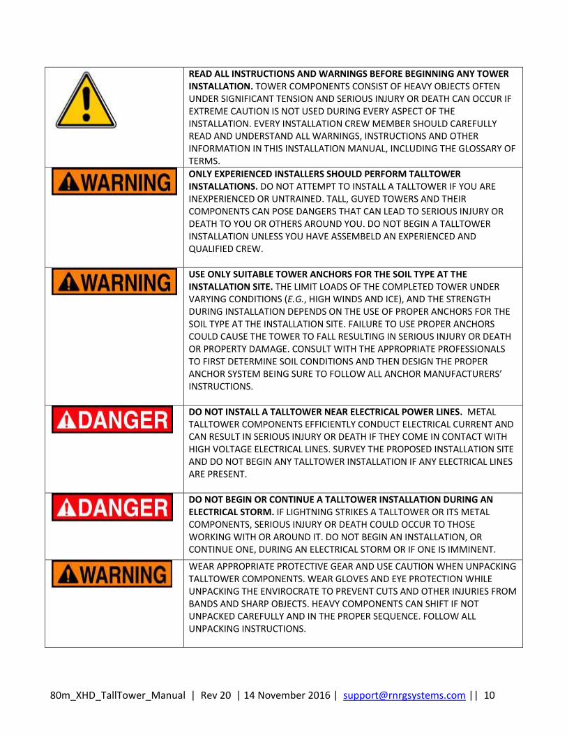
READ ALL INSTRUCTIONS AND WARNINGS BEFORE BEGINNING ANY TOWER INSTALLATION. TOWER COMPONENTS CONSIST OF HEAVY OBJECTS OFTEN UNDER SIGNIFICANT TENSION AND SERIOUS INJURY OR DEATH CAN OCCUR IF EXTREME CAUTION IS NOT USED DURING EVERY ASPECT OF THE INSTALLATION. EVERY INSTALLATION CREW MEMBER SHOULD CAREFULLY READ AND UNDERSTAND ALL WARNINGS, INSTRUCTIONS AND OTHER INFORMATION IN THIS INSTALLATION MANUAL, INCLUDING THE GLOSSARY OF TERMS.
ONLY EXPERIENCED INSTALLERS SHOULD PERFORM TALLTOWER INSTALLATIONS. DO NOT ATTEMPT TO INSTALL A TALLTOWER IF YOU ARE INEXPERIENCED OR UNTRAINED. TALL, GUYED TOWERS AND THEIR COMPONENTS CAN POSE DANGERS THAT CAN LEAD TO SERIOUS INJURY OR DEATH TO YOU OR OTHERS AROUND YOU. DO NOT BEGIN A TALLTOWER INSTALLATION UNLESS YOU HAVE ASSEMBELD AN EXPERIENCED AND QUALIFIED CREW.
USE ONLY SUITABLE TOWER ANCHORS FOR THE SOIL TYPE AT THE INSTALLATION SITE. THE LIMIT LOADS OF THE COMPLETED TOWER UNDER VARYING CONDITIONS (E.G., HIGH WINDS AND ICE), AND THE STRENGTH DURING INSTALLATION DEPENDS ON THE USE OF PROPER ANCHORS FOR THE SOIL TYPE AT THE INSTALLATION SITE. FAILURE TO USE PROPER ANCHORS COULD CAUSE THE TOWER TO FALL RESULTING IN SERIOUS INJURY OR DEATH OR PROPERTY DAMAGE. CONSULT WITH THE APPROPRIATE PROFESSIONALS TO FIRST DETERMINE SOIL CONDITIONS AND THEN DESIGN THE PROPER ANCHOR SYSTEM BEING SURE TO FOLLOW ALL ANCHOR MANUFACTURERS’ INSTRUCTIONS.
DO NOT INSTALL A TALLTOWER NEAR ELECTRICAL POWER LINES. METAL TALLTOWER COMPONENTS EFFICIENTLY CONDUCT ELECTRICAL CURRENT AND CAN RESULT IN SERIOUS INJURY OR DEATH IF THEY COME IN CONTACT WITH HIGH VOLTAGE ELECTRICAL LINES. SURVEY THE PROPOSED INSTALLATION SITE AND DO NOT BEGIN ANY TALLTOWER INSTALLATION IF ANY ELECTRICAL LINES ARE PRESENT.
DO NOT BEGIN OR CONTINUE A TALLTOWER INSTALLATION DURING AN ELECTRICAL STORM. IF LIGHTNING STRIKES A TALLTOWER OR ITS METAL COMPONENTS, SERIOUS INJURY OR DEATH COULD OCCUR TO THOSE WORKING WITH OR AROUND IT. DO NOT BEGIN AN INSTALLATION, OR CONTINUE ONE, DURING AN ELECTRICAL STORM OR IF ONE IS IMMINENT.
WEAR APPROPRIATE PROTECTIVE GEAR AND USE CAUTION WHEN UNPACKING TALLTOWER COMPONENTS. WEAR GLOVES AND EYE PROTECTION WHILE UNPACKING THE ENVIROCRATE TO PREVENT CUTS AND OTHER INJURIES FROM BANDS AND SHARP OBJECTS. HEAVY COMPONENTS CAN SHIFT IF NOT UNPACKED CAREFULLY AND IN THE PROPER SEQUENCE. FOLLOW ALL UNPACKING INSTRUCTIONS.

80m_XHD_TallTower_Manual | Rev 20 | 14 November 2016 | [email protected] || 11
CARELESSNESS DURING TOWER INSTALLATION CAN CAUSE SERIOUS INJURY OR DEATH. AN IMPROPERLY INSTALLED TALLTOWER CAN ALSO CAUSE SERIOUS INJURY OR DEATH. FOR YOUR SAFETY AND THE SAFETY OF OTHERS ON THE INSTALLATION CREW, AS WELL AS THOSE IN THE VICINITY OF A COMPLETED TOWER.

80m_XHD_TallTower_Manual | Rev 20 | 14 November 2016 | [email protected] || 12
1.3 SAFETY CONSIDERATIONS FOR TOWER INSTALLATIONS IN AGRICULTURAL AREAS OR REMOTE AREAS WHERE LOW FLYING AIRCRAFT OPERATE
Renewable NRG Systems manufactures FAA compliant painted towers for use in agricultural areas. In addition, a variety of visibility enhancement accessories, including FAA compliant aviation obstruction lighting kits, high visibility cable ball kits, and guy wire guards, are available from Renewable NRG Systems for use with such installations. If the installation of a MET is being proposed for an agricultural area or in remote areas where low flying aircraft operate, Renewable NRG Systems strongly recommends those involved in the project do ALL of the following: Become familiar with any and all applicable Federal Aviation Administration (FAA) tower visibility and lighting requirements, including FAA Advisory Circular AC 70/7460-1L “Obstruction Marking and Lighting” dated December 4, 2015 and as revised, and ensure the installation complies with those standards and any recommendations contained therein, including but not limited to the following: a. Voluntary marking of meteorological towers less than 200 feet (61 m) AGL in accordance with marking guidance contained in the FAA Advisory Circular AC70/7460-1L. b. Painting with alternate bands of aviation orange and white paint in accordance with Chapter 3, paragraphs 3.1 through 3.4 of the FAA Advisory Circular AC70/7460-1L. c. Utilizing several high visibility sleeves (guy guards) on outer guy wires. d. Attaching spherical marker (cable) balls to the guy wires. Aviation orange marker balls should be installed according to Chapter 3, paragraph 3.5 of the FAA Advisory Circular AC70/7460-1L; Contact the FAA’s Obstruction Evaluation/Airport Airspace Analysis (OE/AAA) office (http:// oeaaa.faa.gov) to discuss whether a “Notice of Proposed Construction or Alteration” form (FAA Form 7460-1) is required; Contact the nearest FAA Regional or District Office regarding installation reporting requirements (www.faa.gov/airports/news_information/contact_info/?s); Become familiar with any and all state and local statutes, ordinances, zoning or other regulations regarding tower visibility and lighting requirements, as some states have enacted statutes or regulations – as have many local jurisdictions – which may affect tower visibility and lighting and which may differ from FAA requirements;
ALWAYS USE VISIBILITY ENHANCING DEVICES ON TALLTOWERS INSTALLED IN AGRICULTURAL AREAS WHERE LOW FLYING AIRCRAFT OPERATE. The installation of talltowers in agricultural areas can pose a serious risk to low-flying aircraft. Physical contact between an agricultural aircraft and any part of a talltower or its guy wire system can result in serious injury or death. It is therefore imperative that landowners, developers, wind energy consultants and installers each consider this serious safety risk for any wind energy project proposed for installation in an agricultural area
80m_XHD_TallTower_Manual | Rev 20 | 14 November 2016 | [email protected] || 13
Contact local regulatory agencies (e.g., city and county building departments) to determine if there are any local zoning regulations relating to the installation; Investigate whether agricultural aviation is present at or around the installation site(s) under consideration, including contacting state and local farm bureaus and/or state or national agricultural aviation organizations (e.g., National Agricultural Aviation Association [http://www.agaviation.org]), and; Contact local landowners, farming operations and agricultural operators and notify them of a proposed or completed installation, including specific GPS coordinates.
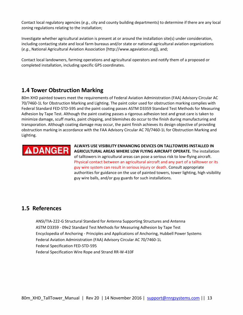
1.4 Tower Obstruction Marking 80m XHD painted towers meet the requirements of Federal Aviation Administration (FAA) Advisory Circular AC 70/7460-1L for Obstruction Marking and Lighting. The paint color used for obstruction marking complies with Federal Standard FED-STD-595 and the paint coating passes ASTM D3359 Standard Test Methods for Measuring Adhesion by Tape Test. Although the paint coating passes a rigorous adhesion test and great care is taken to minimize damage, scuff marks, paint chipping, and blemishes do occur to the finish during manufacturing and transporation. Although coating damage may occur, the paint finish achieves its design objective of providing obstruction marking in accordance with the FAA Advisory Circular AC 70/7460-1L for Obstruction Marking and Lighting.
ALWAYS USE VISIBILITY ENHANCING DEVICES ON TALLTOWERS INSTALLED IN AGRICULTURAL AREAS WHERE LOW FLYING AIRCRAFT OPERATE. The installation of talltowers in agricultural areas can pose a serious risk to low-flying aircraft. Physical contact between an agricultural aircraft and any part of a talltower or its guy wire system can result in serious injury or death. Consult appropriate authorities for guidance on the use of painted towers, tower lighting, high visibility guy wire balls, and/or guy guards for such installations.
1.5 References
ANSI/TIA-222-G Structural Standard for Antenna Supporting Structures and Antenna
ASTM D3359 - 09e2 Standard Test Methods for Measuring Adhesion by Tape Test
Encyclopedia of Anchoring - Principles and Applications of Anchoring, Hubbell Power Systems
Federal Aviation Administration (FAA) Advisory Circular AC 70/7460-1L
Federal Specification FED-STD-595
Federal Specification Wire Rope and Strand RR-W-410F
80m_XHD_TallTower_Manual | Rev 20 | 14 November 2016 | [email protected] || 14
Chapter 2: Pre-Installation Guidelines
2.1 TallTower History RNRG TallTowers™, the original tilt-up tubular towers, were first introduced in 1982 and quickly became the industry standard to quickly and easily get sensors up and into the wind to start measurements. TallTowers are delivered in complete kits, assembled on the ground and then tilted up and secured with guy wires. The 80-meter XHD TallTower is ice-rated for extreme climates and meets the applicable sections of ANSI/TIA-222-G Standards.
2.2 Construction and Assembly The RNRG 80m TallTower™ is constructed of galvanized steel tube and is guyed at eight levels in four directions. Sections slide together and are secured using fasteners. The tower is tilted up from the ground with a gin pole and winch (not included). Lifting of the tower is accomplished using eight lifting wires attached to the gin pole. The tower is stabilized using four guy wire sets. The base plate is hinged so both the tower and ginpole can pivot to the erected position.
2.3 Required Parts to Erect Tower System RNRG 80 meter XHD TallTowers are supplied complete with ready to assemble tubes, baseplate, guy rings, precut guy wires, grounding kit, and associated hardware. Anchors are optional. Several types of anchors, suitable for many soil types, are available from RNRG. It is your responsibility to determine which type of anchor is appropriate for your specific site. Please refer to Appendix B: Anchoring Guidelines of this manual for more information. A winch and ginpole are also required to raise the tower. When combined, a winch and ginpole comprise an installation kit. The installation kit (winch and ginpole) can be transported from one site to another to raise and lower the 80 meter XHD tower. The winch and ginpole for the 80 m XHD TallTower are NOT compatible with other RNRG TallTowers and SHALL NOT be used for applications other than raising and lowering the RNRG 80m XHD TallTower. The Back Stay Tensioning System is also required to raise the the tower. Please refer to Appendix E: RNRG 80m XHD TallTower Back Guywire Tensioner Assembly and Operating Instructions.

80m_XHD_TallTower_Manual | Rev 20 | 14 November 2016 | [email protected] || 15
2.4 Experience Required
Extensive experience installing other TallTowers is required for successful installation of the 80 m XHD TallTower.
Contact Renewable NRG Systems for referral to qualified installers.
2.5 Tower Lift Crew We suggest the following organization to form an efficient and safe crew to erect RNRG TallTowers. Each member of the lift crew should have a good understanding of the tasks they are required to perform during the lift. 1. “Qualified Installer” Defined: As used herein, the term “Qualified Installer” is defined as a person or
entity that meets the following criteria:
a. A Team Leader or Foreman who has successfully supervised the installation of at least 20 RNRG 60m
XHD TallTowers, the most recent of which was within the last 3 years AND has been trained by
Renewable NRG Systems AND utilizes a Crew/Team of at least 6 people who have each assisted with
the installation of at least 3 tilt-up towers.
OR b. A Team Leader or Foreman who has successfully supervised the installation of at least 2 RNRG 80m
XHD TallTowers, the most recent of which was within the last 3 years, AND has been trained by
Renewable NRG Systems AND utilizes a Crew/Team of at least 6 people who have each assisted with
the installation of at least 3 tilt-up towers.
OR c. A Team Leader or Foreman of an installation crew who is a Renewable RNG Systems employee who
has been trained and has field experience in the installation, raising and lower of all models of RNRG
TallTowers.
Six (6) Member Crew (MINIMUM): Crew leader (1): This person will coordinate the other members. It is especially important to maintain clear communication among the members of the crew. The tower footprint is large and walkie-talkie radios are highly recommended. Winch operator (1): This person operates the winch and HPU, following the direction given by the crew leader.
80m_XHD_TallTower_Manual | Rev 20 | 14 November 2016 | [email protected] || 16
Side guy wire tenders (4): Four (4) people to assist adjusting side guy wires (two (2) on each side). They must be familiar with taking in and letting out guy wire tension. See 4.3 Lifting the tower for details. See the section entitled Adjusting Guy Wires for details on adjusting guy wires.
Depending on the site terrain and other factors, it may be more efficient to have a larger crew than to reallocate members of a smaller crew. Plan accordingly and contact RNRG Systems with any questions regarding crew size.
2.6 Using This Manual The single configuration for the 80 m XHD TallTower consists of an 81.3m height and a single guy anchor footprint. This manual provides detailed information on the installation and specifications of the 80m XHD TallTower. Wind and ice loadings are included in the body of the manual along with anchor and baseplate loads, parts lists, a site layout map, and tower assembly drawings. Critical installation steps are highlighted throughout the manual as shown below.
SAFETY CONSIDERATIONS:
Recommendation:
It is recommended that you use widely available and inexpensive digitial camera technology to record the tower lift as an educational tool for future tower installations and as a way to continuously improve your tower installation procedures.
2.7 Tools
2.7.1 Tools Supplied with Tower Kits
Metal rust-prevention compound (such as Sanchem, Inc. NO-OX-ID "A-SPECIAL")
2.7.2 Tools Supplied with Installation Toolkit #4832
Klein Tools, Inc. Chicago Grip (PN 1659-20) (3)
Lug-All Come-Along (Model 115-R) (3)
Loos & Co. Inc. Model PT-3 Tension Gauge (1)
2.7.3 Tools Required but not Supplied
¼ inch nut driver (for sensor installation)
5/16 inch nut driver (for hose clamps)
Torque wrenches for wire rope clips (see Table 2-1)
Failure to follow critical installation steps precisely may result in catastrophic failure of the ginpole or tower and endanger the lives of crew members.
80m_XHD_TallTower_Manual | Rev 20 | 14 November 2016 | [email protected] || 17
Torque wrench capable of applying 150 ft-lbs of torque (to tighten 5/8”-11 tower tube joint nuts
using a 1- 1/16” socket)
Small adjustable wrench (for opening/closing acorn clamps)
Small pliers (for sensor cotter pins)
Small Phillips head (+) screwdriver (for set screws)
Flat (-) screwdriver (for antenna mounting assembly)
Wood blocks (for tube layout and seating tower joints)
Mallet (for seating tower joints and installing ground rods)
Large adjustable wrench (for large bolts)
Hand sledge (for ground rods)
Level, preferably with a magnetic base (to straighten the tower)
Compass (for aligning direction sensors)
Permanent marker (for labeling lower ends of cables)
Anti-Seize
Gloves
Wire cutters
2-way radios or walkie talkies
Electric drill with 5/16 inch bit (for unpacking EnviroCrate)
9/16 inch wrench, socket or open-end (for base plate assembly and unpacking EnviroCrate)
Band cutters (for unpacking EnviroCrate)
10 ft (3 m) stepladder (for reaching top of helper ginpole)
Nylon slings (2) with minimum Working Load Limit (WLL) of 6000 lbf (basket hitch)
For use in installing 203 mm (8.0 inch) diameter twin helix anchors (available from Hubbell
Power Systems): Locking Dog assembly, Drive Wrench
(2) Cordless drills with spare batteries to adjust worm gear winches
11/16” socket for tightening 5/16” wire rope clips
¾” socket for tightening 3/8” wire rope clips and adjusting worm gears
Table 2-1: Wire Rope Clips, Socket Sizes, and Torque Requirements
Wire Rope Clip (inches) Socket Diameter (inches) Torque Wrench N-m (ft-lbf)
3/16 7/16 10 (7.5)
5/16 11/16 41 (30)
3/8 3/4 61 (45)
Table 2.2: Bolt Diameters and Socket Sizes
Bolt Diameter (inches) Socket/Wrench Diameter (inches)
3/8 9/16
½ ¾
5/8 1-1/16
¾ 1-1/8
80m_XHD_TallTower_Manual | Rev 20 | 14 November 2016 | [email protected] || 18
2.8 Unpack Your Tower
2.8.1 Description of the Envirocrate packaging
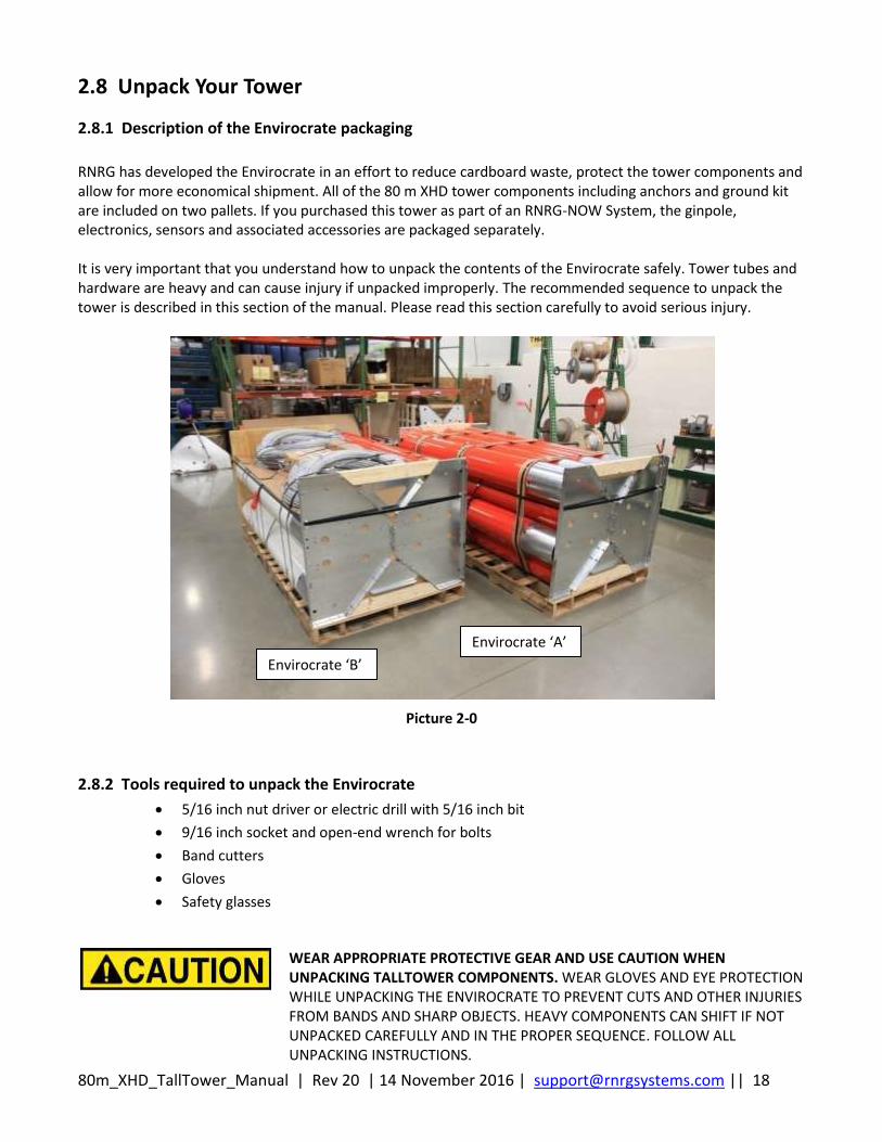
RNRG has developed the Envirocrate in an effort to reduce cardboard waste, protect the tower components and allow for more economical shipment. All of the 80 m XHD tower components including anchors and ground kit are included on two pallets. If you purchased this tower as part of an RNRG-NOW System, the ginpole, electronics, sensors and associated accessories are packaged separately. It is very important that you understand how to unpack the contents of the Envirocrate safely. Tower tubes and hardware are heavy and can cause injury if unpacked improperly. The recommended sequence to unpack the tower is described in this section of the manual. Please read this section carefully to avoid serious injury.
Picture 2-0
2.8.2 Tools required to unpack the Envirocrate
5/16 inch nut driver or electric drill with 5/16 inch bit
9/16 inch socket and open-end wrench for bolts
Band cutters
Gloves
Safety glasses
WEAR APPROPRIATE PROTECTIVE GEAR AND USE CAUTION WHEN UNPACKING TALLTOWER COMPONENTS. WEAR GLOVES AND EYE PROTECTION WHILE UNPACKING THE ENVIROCRATE TO PREVENT CUTS AND OTHER INJURIES FROM BANDS AND SHARP OBJECTS. HEAVY COMPONENTS CAN SHIFT IF NOT UNPACKED CAREFULLY AND IN THE PROPER SEQUENCE. FOLLOW ALL UNPACKING INSTRUCTIONS.
Envirocrate ‘A’
Envirocrate ‘B’

80m_XHD_TallTower_Manual | Rev 20 | 14 November 2016 | [email protected] || 19
2.8.3 Envirocrate Access and Orientation
Ideally, you will want access to both ends of the Envirocrates to unpack the contents. If a forklift is available, that is also ideal. Remove the EnviroCrates from the truck with the forklift and set them on an unobstructed flat area before unpacking. It is also possible to unpack the contents with access to only one end of the Envirocrates. For example, the Envirocrate may have been placed into a truck with one end against the front wall of the truck’s cargo area and no forklift available to remove the Envirocrate from the truck. In this case, you will be able to follow instructions in this section of the manual to unpack the contents and unload from the truck by hand. Note: You will NOT be able to unpack the contents of the Envirocrate if the Envirocrate has been loaded into a truck sideways. If the Envirocrate has been loaded into a truck sideways, you will not have the required access to the ends and will need a forklift to remove the Envirocrate.
2.8.4 Envirocrate Unpack Sequence – Very Important!
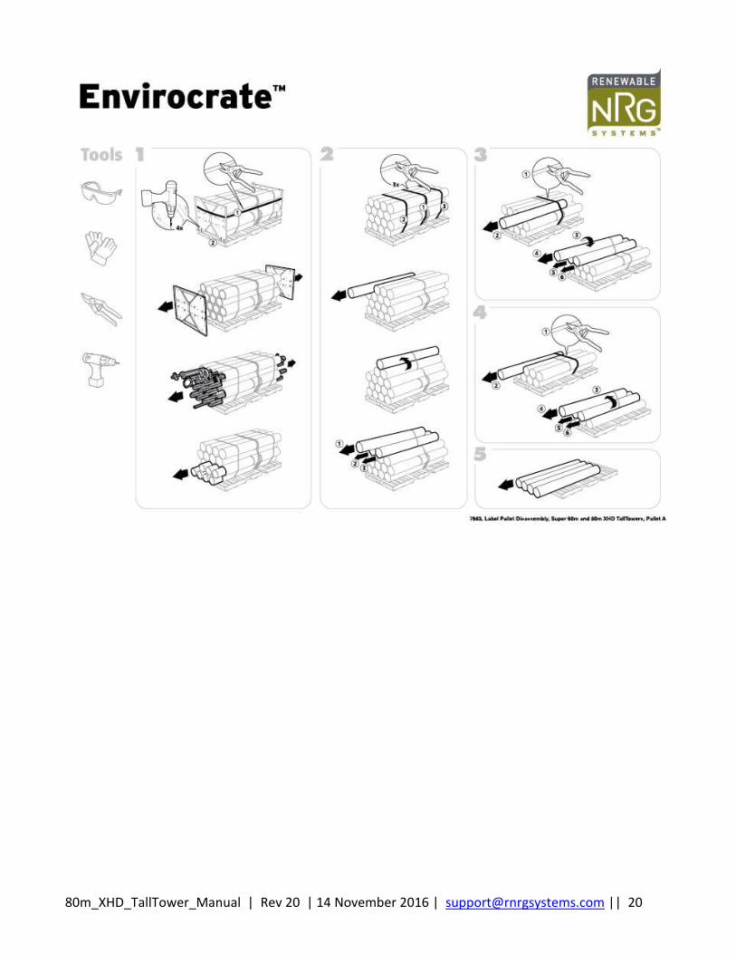
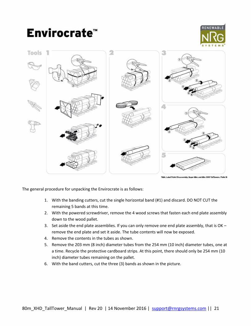
The RNRG 80m XHD TallTower ships in two (2) Pallets, Envirocrate Pallet A and Envirocrate Pallet B, as shown in picture 2-0 above. The sequence for unpacking the Envirocrate A and B is shown graphically in the pictures below.
USE EXTREME CAUTION WHEN UNPACKING HEAVY TALLTOWER COMPONENTS. LOOSE TALLTOWER COMPONENTS CAN CAUSE SERIOUS CRUSHING INJURIES DURING UNPACKING IF CARE IS NOT TAKEN. ALWAYS FOLLOW UNPACKING INSTRUCTIONS CAREFULLY, AND USE SUFFICIENT INSTALLATION CREW MEMBERS TO REMOVE TALLTOWER COMPONENTS FROM THE ENVIROCRATE PACKAGING IN THE PROPER SEQUENCE.
80m_XHD_TallTower_Manual | Rev 20 | 14 November 2016 | [email protected] || 20
80m_XHD_TallTower_Manual | Rev 20 | 14 November 2016 | [email protected] || 21
The general procedure for unpacking the Envirocrate is as follows:
1. With the banding cutters, cut the single horizontal band (#1) and discard. DO NOT CUT the
remaining 5 bands at this time.
2. With the powered screwdriver, remove the 4 wood screws that fasten each end plate assembly
down to the wood pallet.
3. Set aside the end plate assemblies. If you can only remove one end plate assembly, that is OK –
remove the end plate and set it aside. The tube contents will now be exposed.
4. Remove the contents in the tubes as shown.
5. Remove the 203 mm (8 inch) diameter tubes from the 254 mm (10 inch) diameter tubes, one at
a time. Recycle the protective cardboard strips. At this point, there should only be 254 mm (10
inch) diameter tubes remaining on the pallet.
6. With the band cutters, cut the three (3) bands as shown in the picture.
80m_XHD_TallTower_Manual | Rev 20 | 14 November 2016 | [email protected] || 22
Envirocrate A:
Note that one top layer tube is now free and can be removed. DO NOT CUT the inner 3 bands
that are marked with the "DO NOT CUT" tags. These are safety bands that never need to be cut.
The three remaining sections of 254 mm (10 inch) diameter tubing on the top layer are
restrained by a small metal safety band (marked with a “DO NOT CUT” tag). These can be safely
rearranged without cutting that band by lifting the tube closest to the edge of the EnviroCrate
and nesting it on the two other tubes, and the safety band will go slack. Now you may slide this
top tube out from underneath the safety band and remove it from the pallet.
Remove the remaining two tubes from the top layer (these two tubes were within the safety
band).
With the band cutters, cut another cross-band, and remove the next layer of tubes in the same
manner described above. Repeat until the pallet is disassebled.
Envirocrate B:
Remove guywires #7 and #8, transition tube, and guy rings and tower pivot pin (boxed).
Reposition the top 254 mm (10 inch) diameter tube and nest it between two inside tubes. The
safety band will go slack. Now you may slide this top tube out from underneath the safety band
and remove it from the pallet.
With the band cutters, cut another cross-band, and remove the next layer of tubes in the same
manner described above. Repeat until the pallet is disassebled.
80m_XHD_TallTower_Manual | Rev 20 | 14 November 2016 | [email protected] || 23
2.9 Site Layout
2.9.1 Pre-installation Planning
The RNRG 80 m XHD TallTower may require a site permit prior to installation. Check with local building codes or town authorities regarding site permitting. It is essential to visit the site before you order your wind measurement system. You will need to make arrangements regarding how to unload your tower system. Some site preparation may also be necessary.
2.9.2 Soil Type and Anchors
Before ordering your tower, determine the site soil and anchor type required. Per ANSI/TIA-222-G, for design purposes, one can assume Class 6 soils. However, the Standard requires that soil parameters and assumptions be validated prior to installing the tower. It is your responsibility to determine which type of anchor is appropriate for your specific site. Depending on the soil type, anchoring can take varying levels of planning, effort and time. Be sure to know what soil types you are dealing with as part of your pre-installation planning process. The 80 m XHD TallTower anchors require mechanical means to install. In addition, all anchors shall be pull tested to 66.7 kN (15000 lbf) prior to tower erection. The 19.5 ft2 baseplate is sized to ensure the factored resistance of Clay soil (Class 6) is greater than the reactions from the factored loads per ANSI/TIA-222-G. If actual soil conditions depart from these assumptions, it may be necessary to provide a foundation to ensure adequate bearing strength. Please refer to the anchoring guidelines in Appendix B: Anchoring Guidelines and Appendix H: ANSI/TIA-222-G Foundation Considerations of this manual for more information.
USE ONLY SUITABLE TOWER ANCHORS FOR THE SOIL TYPE AT THE INSTALLATION SITE. STABILITY OF THE COMPLETED TOWER UNDER VARYING CONDITIONS (E.G., HIGH WINDS AND ICE), AND STABILITY DURING INSTALLATION, DEPENDS ON THE USE OF PROPER ANCHORS FOR THE SOIL TYPE AT THE INSTALLATION SITE. FAILURE TO USE PROPER ANCHORS COULD CAUSE THE TOWER TO FALL CAUSING SERIOUS INJURY OR DEATH OR PROPERTY DAMAGE. CONSULT WITH THE APPROPRIATE PROFESSIONALS TO FIRST DETERMINE SOIL CONDITIONS AND THEN SELECT THE PROPER ANCHOR SYSTEM BEING SURE TO FOLLOW ALL ANCHOR MANUFACTURER’S INSTRUCTIONS.
Tip: Cellular Coverage
This is also a good opportunity to identify what type of cellular service is available at the site for those who will be using an RNRG iPack to transmit data. For more information on RNRG iPacks, contact RNRG.
80m_XHD_TallTower_Manual | Rev 20 | 14 November 2016 | [email protected] || 24
2.10 Site Layout Map The RNRG 80m XHD TallTower is suitable for installation in flat or rolling terrain with slopes less than or equal to 3° (1:20). Picture 2-1 shows the permissible terrain/slope combinations. Do not install this tower on slopes greater than 3° (1:20) or in sites where it is greater than 3° down from the baseplate to both the tower and the winch anchor.
INSTALLING TOWERS ON SLOPED TERRAIN CAN CAUSE EXCESSIVE GUY WIRE LOADS AND INSTABILITY DURING INSTALLATION. DO NOT INSTALL TALLTOWERS ON SLOPES GREATER THAN 3° (1:20) AS INSTABILITY CAN RESULT CAUSING SERIOUS INJURY OR DEATH. CAREFULLY READ AND FOLLOW ALL APPLICABLE INSTRUCTIONS ON INSTALLATIONS WHERE A SLOPE OF LESS THAN 3° IS PRESENT.
2.10.1 Slopes Greater than +1.5°
For slopes greater than +1.5° up from the baseplate-to-ginpole, the ginpole jumper struts will likely contact the ground before the tower reaches vertical. In this case, you will need to do one or all of the following:
Proceed with the tower raising as you normally would following the instructions in this Manual.
When the tower is near vertical and the lower jumper struts are nearing ground contact, de-
tension all four (4) jumper strut wires by loosening each of the four (4) turnbuckles. After de-
tensioning the jumper strut wires, remove one of the two jumper strut mounting bolts (from the
bottom jumper struts) and swing the lower jumper struts out-of-the-way. Proceed with the
tower raising.
Proceed with the tower raising as you normally would following the instructions in this Manual.
When the tower is near vertical and the lower jumper struts are nearing ground contact, STOP
the tower raising. The tower will be near-vertical but not at 90°. Attach the front guys to their
respective anchors (see 4.4 Attaching Front Guy for more detail). Follow the procedures
outlined in 4.5 Plumb and Straighten Tower to plumb the tower. Anticipate it taking longer to
plumb the tower since the tower has to physically move a greater distance.
Perform site work before assembling the ginpole. Using an excavator or other suitable device,
dig a hole 0.3 m (1 ft) in depth, approximately 9.4 m (31 ft) from the tower baseplate (in the
direction of the final ginpole position) so that the ginpole jumper strut tips will not contact the
ground but be below grade when the tower is vertical.
2.10.2 Slopes Less than -2°
For slopes less than -2° down from the baseplate-to-ginpole, the height from the ground to the top of the ginpole (when the tower is vertical) will exceed 8 feet. In this case, RNRG recommends using a 12 foot step ladder to access the top of the ginpole to remove the lifters for storage. Alternatively, one could use scaffolding to access the top of the ginpole if the site permits its transport and you are willing take the necessary steps to set it up.
80m_XHD_TallTower_Manual | Rev 20 | 14 November 2016 | [email protected] || 25
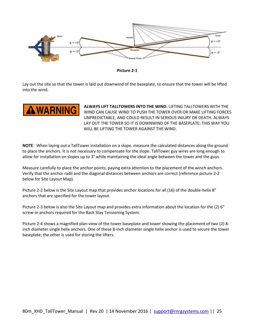
Picture 2-1
Lay out the site so that the tower is laid out downwind of the baseplate, to ensure that the tower will be lifted into the wind.
ALWAYS LIFT TALLTOWERS INTO THE WIND. LIFTING TALLTOWERS WITH THE WIND CAN CAUSE WIND TO PUSH THE TOWER OVER OR MAKE LIFTING FORCES UNPREDICTABLE, AND COULD RESULT IN SERIOUS INJURY OR DEATH. ALWAYS LAY OUT THE TOWER SO IT IS DOWNWIND OF THE BASEPLATE; THIS WAY YOU WILL BE LIFTING THE TOWER AGAINST THE WIND.
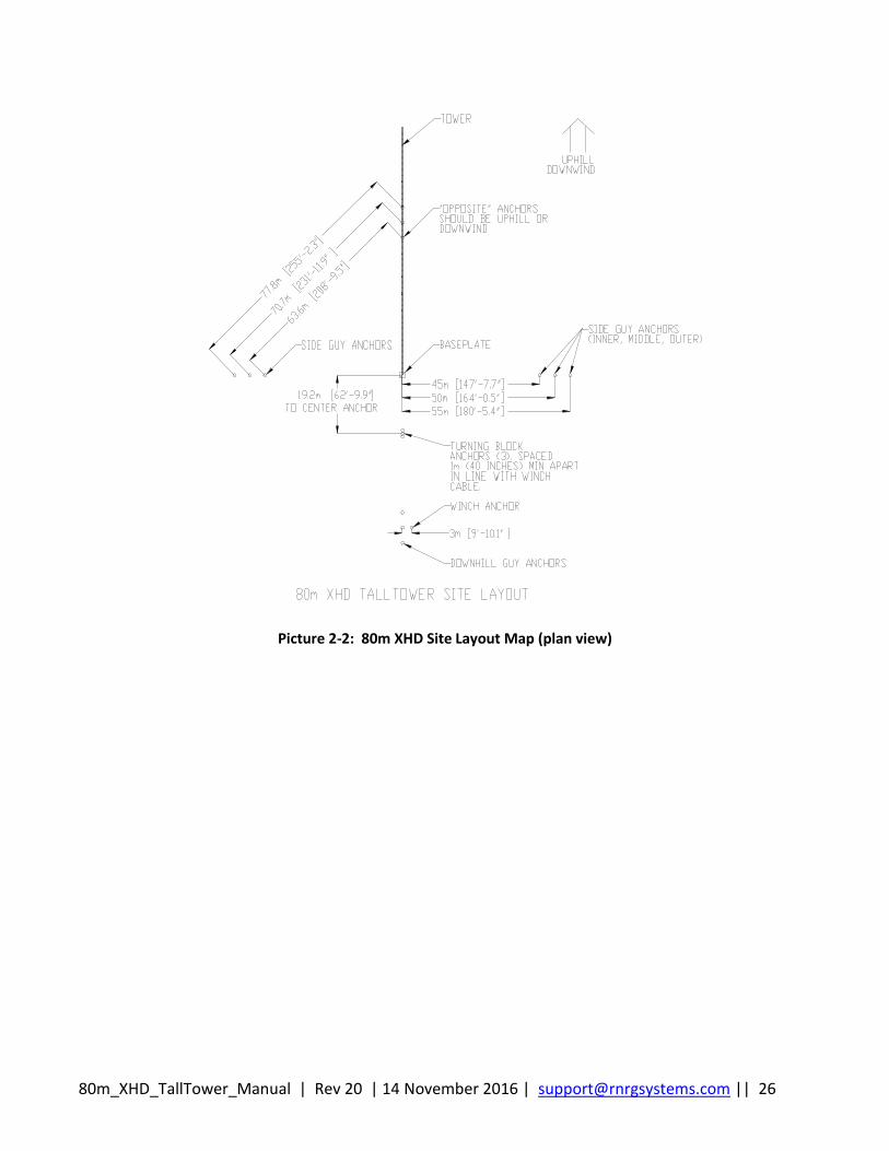
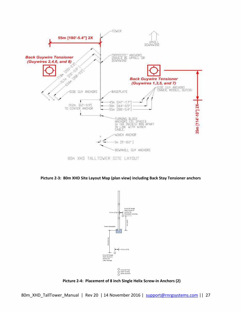
NOTE: When laying out a TallTower installation on a slope, measure the calculated distances along the ground to place the anchors. It is not necessary to compensate for the slope. TallTower guy wires are long enough to allow for installation on slopes up to 3° while maintaining the ideal angle between the tower and the guys. Measure carefully to place the anchor points, paying extra attention to the placement of the winch anchors. Verify that the anchor radii and the diagonal distances between anchors are correct (reference picture 2-2 below for Site Layout Map). Picture 2-2 below is the Site Layout map that provides anchor locations for all (16) of the double-helix 8” anchors that are specified for the tower layout. Picture 2-3 below is also the Site Layout map and provides extra information about the location for the (2) 6” screw-in anchors required for the Back Stay Tensioning System. Picture 2-4 shows a magnified plan-view of the tower baseplate and tower showing the placement of two (2) 8-inch diameter single helix anchors. One of these 8-inch diameter single helix anchor is used to secure the tower baseplate; the other is used for storing the lifters.
80m_XHD_TallTower_Manual | Rev 20 | 14 November 2016 | [email protected] || 26
Picture 2-2: 80m XHD Site Layout Map (plan view)
80m_XHD_TallTower_Manual | Rev 20 | 14 November 2016 | [email protected] || 27
Picture 2-3: 80m XHD Site Layout Map (plan view) including Back Stay Tensioner anchors
8 inch Ø Twin
Helix Turning
Block Anchors
8 inch Ø Single
Helix Screw-in
Anchor for
Lifter Storage
15
ft (4
.6 m
)
0.6 m (2 ft)
8 inch Ø Single
Helix Screw-in
Anchor for
Baseplate securing
Tower Baseplate
0.3 m (1 ft)
3 m
(1
0 ft
Picture 2-4: Placement of 8 inch Single Helix Screw-in Anchors (2)
80m_XHD_TallTower_Manual | Rev 20 | 14 November 2016 | [email protected] || 28
NOTE: The side guy anchors and the base plate should be on a straight line. If it is not possible to place them in the locations shown, it is better to move them in or out along the line to the baseplate than to move them off the line. Do not move them more than 1.5 m (5 feet) off the line. NOTE: Extra care will have to be taken while raising the tower if:
Anchor placement is not perpendicular to the tower as it lays on the ground.
Anchors are not at the same elevation.
Side anchors and base plate are not in a straight line.
Placement of the winch anchors is critical. Make sure that you measure carefully and set the anchor heads close to ground level. Angle all three anchors towards the tower at 45 degrees. All of these factors are important for proper distribution of forces and for clearance and proper operation of the ginpole.
NOTE: Any of these conditions will affect the side guy wire tension and the ginpole safety wire rope tension as the tower is raised. Tension will have to be continuously monitored and periodically adjusted as the tower is lifted.
80m_XHD_TallTower_Manual | Rev 20 | 14 November 2016 | [email protected] || 29
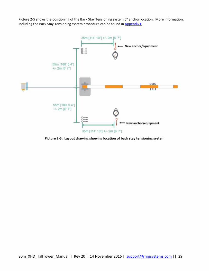
Picture 2-5 shows the positioning of the Back Stay Tensioning system 6” anchor location. More information, including the Back Stay Tensioning system procedure can be found in Appendix E.
Picture 2-5: Layout drawing showing location of back stay tensioning system
80m_XHD_TallTower_Manual | Rev 20 | 14 November 2016 | [email protected] || 30
Chapter 3: Tower Components Assembly
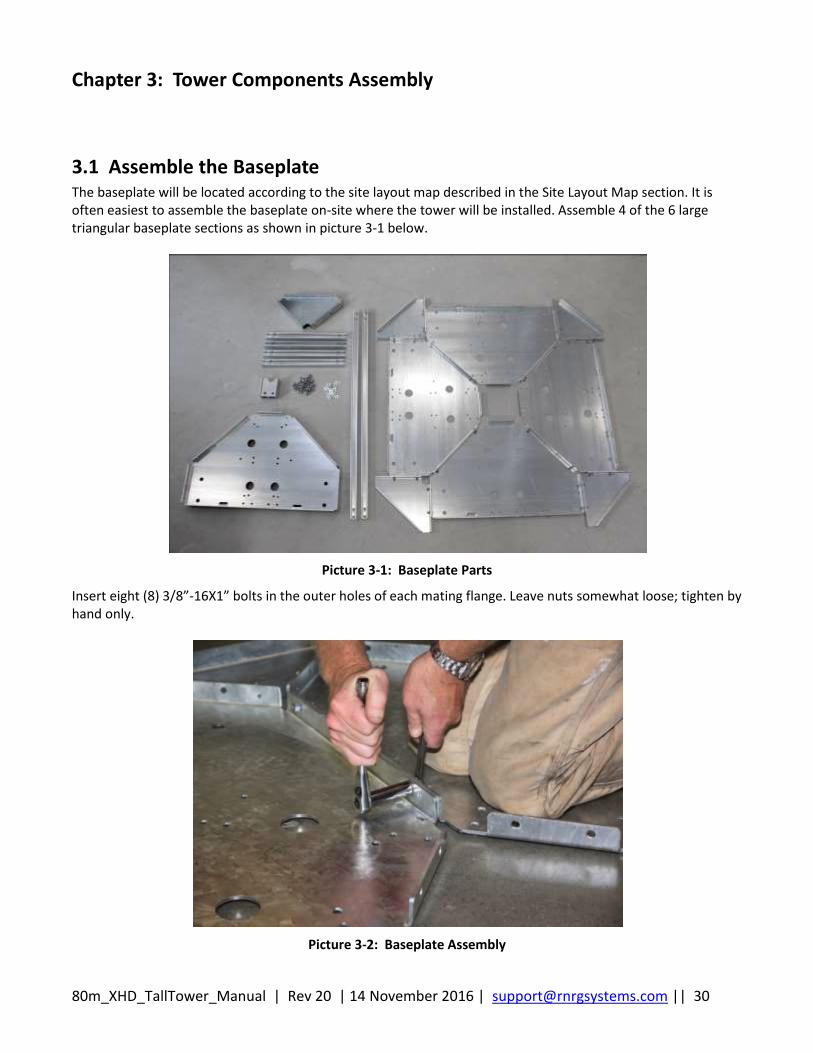
3.1 Assemble the Baseplate The baseplate will be located according to the site layout map described in the Site Layout Map section. It is often easiest to assemble the baseplate on-site where the tower will be installed. Assemble 4 of the 6 large triangular baseplate sections as shown in picture 3-1 below.
Picture 3-1: Baseplate Parts
Insert eight (8) 3/8”-16X1” bolts in the outer holes of each mating flange. Leave nuts somewhat loose; tighten by hand only.
Picture 3-2: Baseplate Assembly
80m_XHD_TallTower_Manual | Rev 20 | 14 November 2016 | [email protected] || 31
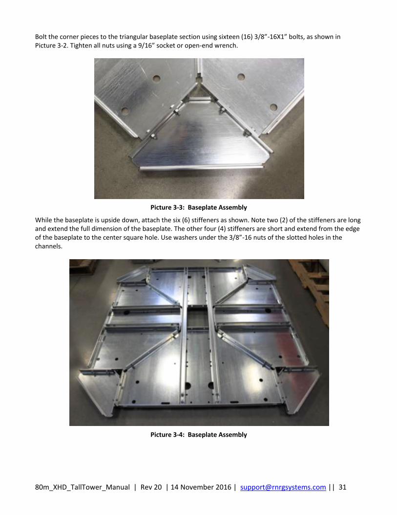
Bolt the corner pieces to the triangular baseplate section using sixteen (16) 3/8”-16X1” bolts, as shown in Picture 3-2. Tighten all nuts using a 9/16” socket or open-end wrench.
Picture 3-3: Baseplate Assembly
While the baseplate is upside down, attach the six (6) stiffeners as shown. Note two (2) of the stiffeners are long and extend the full dimension of the baseplate. The other four (4) stiffeners are short and extend from the edge of the baseplate to the center square hole. Use washers under the 3/8”-16 nuts of the slotted holes in the channels.
Picture 3-4: Baseplate Assembly

80m_XHD_TallTower_Manual | Rev 20 | 14 November 2016 | [email protected] || 32
Flip over the baseplate assembly, and prop up on one edge to allow access to underside of baseplate. Attach the vertical uprights to the center of the baseplate as shown in picture 3-5 below, with flanges facing outward, and with the vertical pieces perpendicular to the two (2) long stiffeners (visible through center hole). Use washers under the nuts to cover the slotted holes.
Picture 3-5: Baseplate Assembly
Picture 3-6: Baseplate Assembly
80m_XHD_TallTower_Manual | Rev 20 | 14 November 2016 | [email protected] || 33
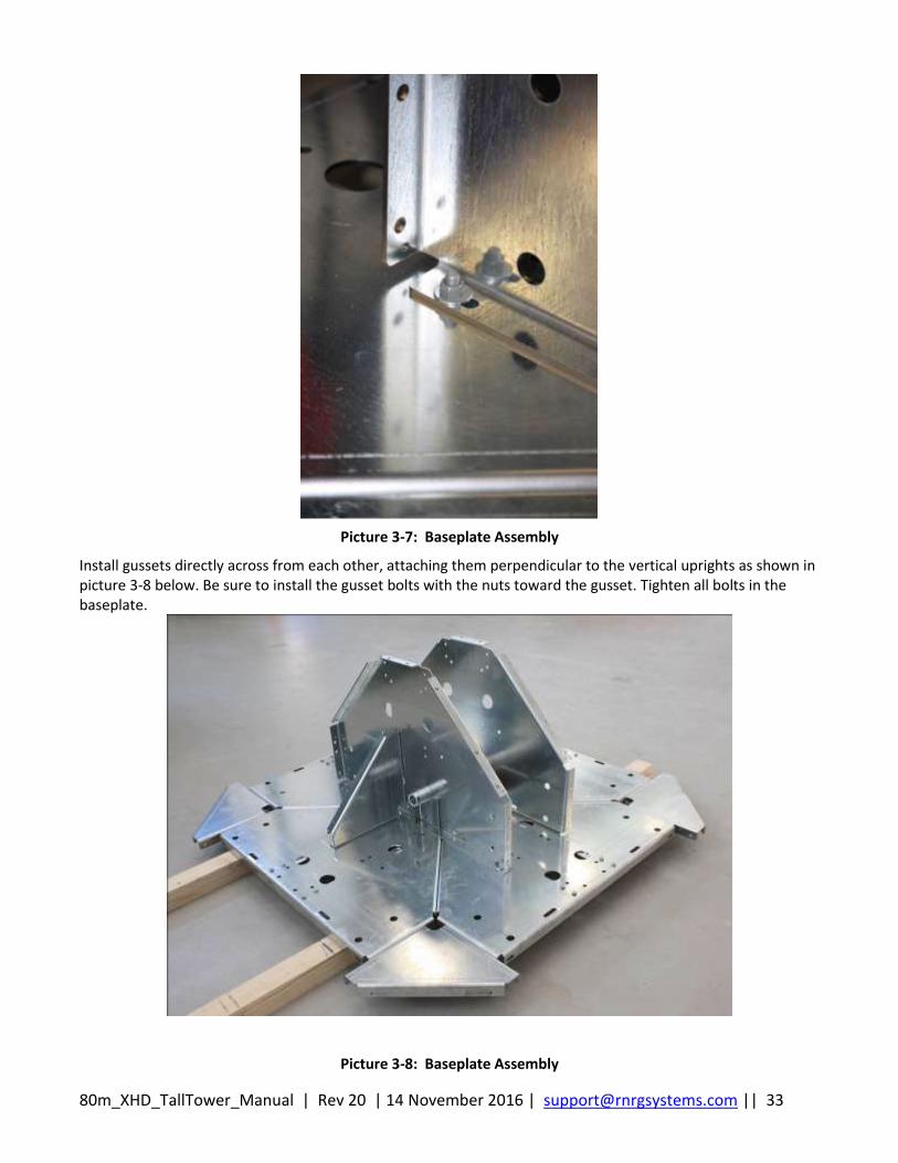
Picture 3-7: Baseplate Assembly
Install gussets directly across from each other, attaching them perpendicular to the vertical uprights as shown in picture 3-8 below. Be sure to install the gusset bolts with the nuts toward the gusset. Tighten all bolts in the baseplate.
Picture 3-8: Baseplate Assembly
80m_XHD_TallTower_Manual | Rev 20 | 14 November 2016 | [email protected] || 34
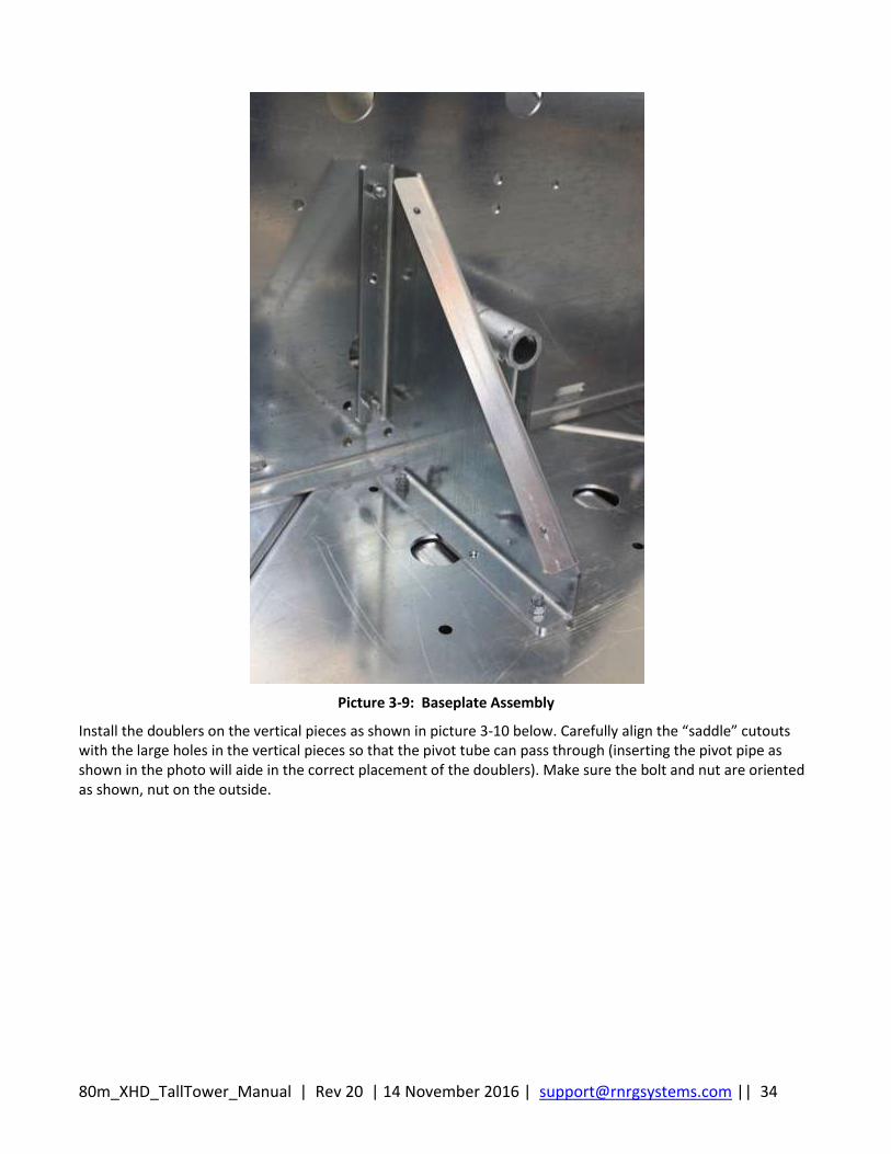
Picture 3-9: Baseplate Assembly
Install the doublers on the vertical pieces as shown in picture 3-10 below. Carefully align the “saddle” cutouts with the large holes in the vertical pieces so that the pivot tube can pass through (inserting the pivot pipe as shown in the photo will aide in the correct placement of the doublers). Make sure the bolt and nut are oriented as shown, nut on the outside.
80m_XHD_TallTower_Manual | Rev 20 | 14 November 2016 | [email protected] || 35
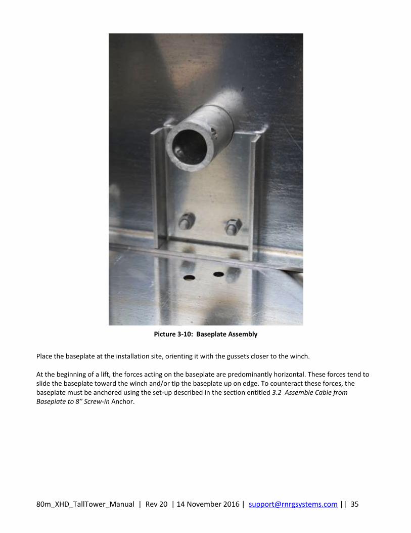
Picture 3-10: Baseplate Assembly
Place the baseplate at the installation site, orienting it with the gussets closer to the winch. At the beginning of a lift, the forces acting on the baseplate are predominantly horizontal. These forces tend to slide the baseplate toward the winch and/or tip the baseplate up on edge. To counteract these forces, the baseplate must be anchored using the set-up described in the section entitled 3.2 Assemble Cable from Baseplate to 8” Screw-in Anchor.

80m_XHD_TallTower_Manual | Rev 20 | 14 November 2016 | [email protected] || 36
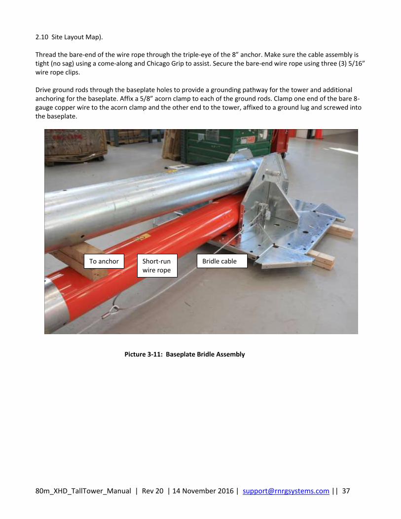
3.2 Assemble Cable from Baseplate to 8” Screw-in Anchor A bridle cable and short-run of wire rope (assembly supplied with the tower) are used to secure the baseplate. The bridle straddles the tower tube pivot pipe, as shown in the picture below. Secure the bare-end of the short-run of wire rope (attached to the bridle) to the 8” screw-in anchor. The 8” screw-in anchor is installed in close proximity to the baseplate (for details on anchoring, see the section entitled
80m_XHD_TallTower_Manual | Rev 20 | 14 November 2016 | [email protected] || 37
2.10 Site Layout Map). Thread the bare-end of the wire rope through the triple-eye of the 8” anchor. Make sure the cable assembly is tight (no sag) using a come-along and Chicago Grip to assist. Secure the bare-end wire rope using three (3) 5/16” wire rope clips. Drive ground rods through the baseplate holes to provide a grounding pathway for the tower and additional anchoring for the baseplate. Affix a 5/8” acorn clamp to each of the ground rods. Clamp one end of the bare 8-gauge copper wire to the acorn clamp and the other end to the tower, affixed to a ground lug and screwed into the baseplate.
Picture 3-11: Baseplate Bridle Assembly
Bridle cable Short-run wire rope
To anchor
80m_XHD_TallTower_Manual | Rev 20 | 14 November 2016 | [email protected] || 38
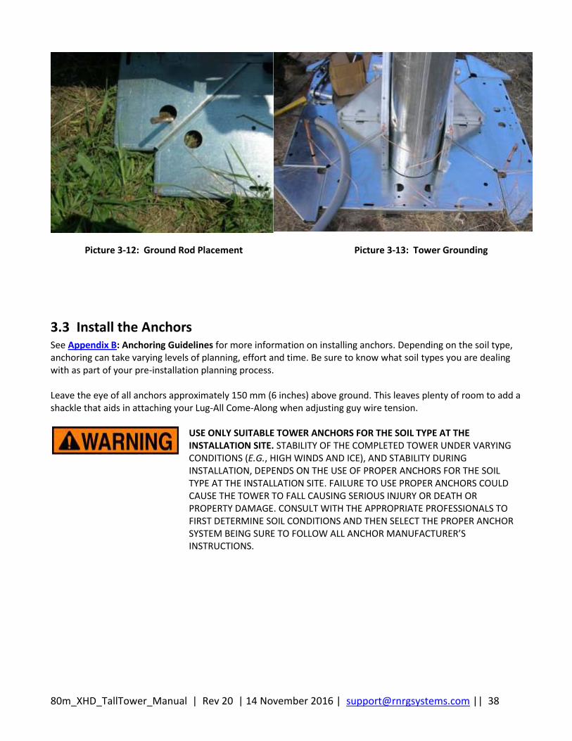
Picture 3-12: Ground Rod Placement Picture 3-13: Tower Grounding
3.3 Install the Anchors See Appendix B: Anchoring Guidelines for more information on installing anchors. Depending on the soil type, anchoring can take varying levels of planning, effort and time. Be sure to know what soil types you are dealing with as part of your pre-installation planning process. Leave the eye of all anchors approximately 150 mm (6 inches) above ground. This leaves plenty of room to add a shackle that aids in attaching your Lug-All Come-Along when adjusting guy wire tension.
USE ONLY SUITABLE TOWER ANCHORS FOR THE SOIL TYPE AT THE INSTALLATION SITE. STABILITY OF THE COMPLETED TOWER UNDER VARYING CONDITIONS (E.G., HIGH WINDS AND ICE), AND STABILITY DURING INSTALLATION, DEPENDS ON THE USE OF PROPER ANCHORS FOR THE SOIL TYPE AT THE INSTALLATION SITE. FAILURE TO USE PROPER ANCHORS COULD CAUSE THE TOWER TO FALL CAUSING SERIOUS INJURY OR DEATH OR PROPERTY DAMAGE. CONSULT WITH THE APPROPRIATE PROFESSIONALS TO FIRST DETERMINE SOIL CONDITIONS AND THEN SELECT THE PROPER ANCHOR SYSTEM BEING SURE TO FOLLOW ALL ANCHOR MANUFACTURER’S INSTRUCTIONS.
80m_XHD_TallTower_Manual | Rev 20 | 14 November 2016 | [email protected] || 39
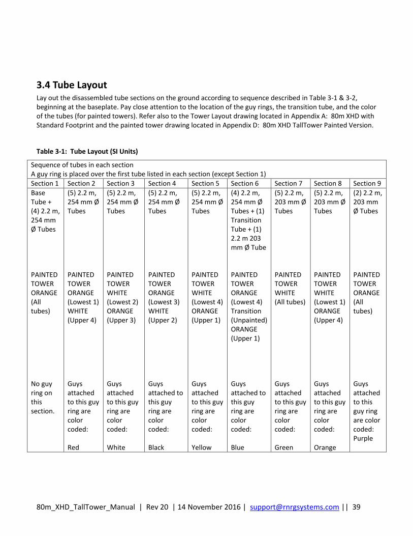
3.4 Tube Layout Lay out the disassembled tube sections on the ground according to sequence described in Table 3-1 & 3-2, beginning at the baseplate. Pay close attention to the location of the guy rings, the transition tube, and the color of the tubes (for painted towers). Refer also to the Tower Layout drawing located in Appendix A: 80m XHD with Standard Footprint and the painted tower drawing located in Appendix D: 80m XHD TallTower Painted Version.
Table 3-1: Tube Layout (SI Units)
Sequence of tubes in each section A guy ring is placed over the first tube listed in each section (except Section 1)
Section 1 Section 2 Section 3 Section 4 Section 5 Section 6 Section 7 Section 8 Section 9
Base Tube + (4) 2.2 m, 254 mm Ø Tubes PAINTED TOWER ORANGE (All tubes) No guy ring on this section.
(5) 2.2 m, 254 mm Ø Tubes PAINTED TOWER ORANGE (Lowest 1) WHITE (Upper 4) Guys attached to this guy ring are color coded: Red
(5) 2.2 m, 254 mm Ø Tubes PAINTED TOWER WHITE (Lowest 2) ORANGE (Upper 3) Guys attached to this guy ring are color coded: White
(5) 2.2 m, 254 mm Ø Tubes PAINTED TOWER ORANGE (Lowest 3) WHITE (Upper 2) Guys attached to this guy ring are color coded: Black
(5) 2.2 m, 254 mm Ø Tubes PAINTED TOWER WHITE (Lowest 4) ORANGE (Upper 1) Guys attached to this guy ring are color coded: Yellow
(4) 2.2 m, 254 mm Ø Tubes + (1) Transition Tube + (1) 2.2 m 203 mm Ø Tube PAINTED TOWER ORANGE (Lowest 4) Transition (Unpainted) ORANGE (Upper 1) Guys attached to this guy ring are color coded: Blue
(5) 2.2 m, 203 mm Ø Tubes PAINTED TOWER WHITE (All tubes) Guys attached to this guy ring are color coded: Green
(5) 2.2 m, 203 mm Ø Tubes PAINTED TOWER WHITE (Lowest 1) ORANGE (Upper 4) Guys attached to this guy ring are color coded: Orange
(2) 2.2 m, 203 mm Ø Tubes PAINTED TOWER ORANGE (All tubes) Guys attached to this guy ring are color coded: Purple
80m_XHD_TallTower_Manual | Rev 20 | 14 November 2016 | [email protected] || 40
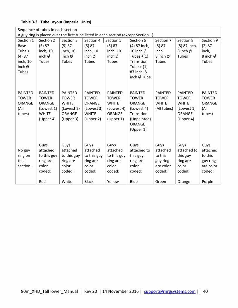
Table 3-2: Tube Layout (Imperial Units)
Sequence of tubes in each section A guy ring is placed over the first tube listed in each section (except Section 1)
Section 1 Section 2 Section 3 Section 4 Section 5 Section 6 Section 7 Section 8 Section 9
Base Tube + (4) 87 inch, 10 inch Ø Tubes PAINTED TOWER ORANGE (All tubes) No guy ring on this section.
(5) 87 inch, 10 inch Ø Tubes PAINTED TOWER ORANGE (Lowest 1) WHITE (Upper 4) Guys attached to this guy ring are color coded: Red
(5) 87 inch, 10 inch Ø Tubes PAINTED TOWER WHITE (Lowest 2) ORANGE (Upper 3) Guys attached to this guy ring are color coded: White
(5) 87 inch, 10 inch Ø Tubes PAINTED TOWER ORANGE (Lowest 3) WHITE (Upper 2) Guys attached to this guy ring are color coded: Black
(5) 87 inch, 10 inch Ø Tubes PAINTED TOWER WHITE (Lowest 4) ORANGE (Upper 1) Guys attached to this guy ring are color coded: Yellow
(4) 87 inch, 10 inch Ø Tubes +(1) Transition Tube + (1) 87 inch, 8 inch Ø Tube PAINTED TOWER ORANGE (Lowest 4) Transition (Unpainted) ORANGE (Upper 1) Guys attached to this guy ring are color coded: Blue
(5) 87 inch, 8 inch Ø Tubes PAINTED TOWER WHITE (All tubes) Guys attached to this guy ring are color coded: Green
(5) 87 inch, 8 inch Ø Tubes PAINTED TOWER WHITE (Lowest 1) ORANGE (Upper 4) Guys attached to this guy ring are color coded: Orange
(2) 87 inch, 8 inch Ø Tubes PAINTED TOWER ORANGE (All tubes) Guys attached to this guy ring are color coded: Purple
80m_XHD_TallTower_Manual | Rev 20 | 14 November 2016 | [email protected] || 41
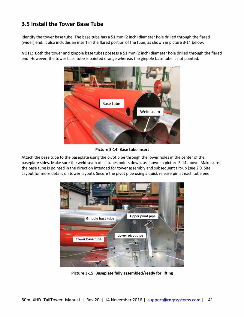
3.5 Install the Tower Base Tube Identify the tower base tube. The base tube has a 51 mm (2 inch) diameter hole drilled through the flared (wider) end. It also includes an insert in the flared portion of the tube, as shown in picture 3-14 below. NOTE: Both the tower and ginpole base tubes possess a 51 mm (2 inch) diameter hole drilled through the flared end. However, the tower base tube is painted orange whereas the ginpole base tube is not painted.
Picture 3-14: Base tube insert
Attach the base tube to the baseplate using the pivot pipe through the lower holes in the center of the baseplate sides. Make sure the weld seam of all tubes points down, as shown in picture 3-14 above. Make sure the base tube is pointed in the direction intended for tower assembly and subsequent tilt-up (see 2.9 Site Layout for more details on tower layout). Secure the pivot pipe using a quick release pin at each tube end.
Ginpole base tube
Tower base tubeLower pivot pipe
Upper pivot pipe
Picture 3-15: Baseplate fully assembled/ready for lifting
Base tube
Weld seam
80m_XHD_TallTower_Manual | Rev 20 | 14 November 2016 | [email protected] || 42
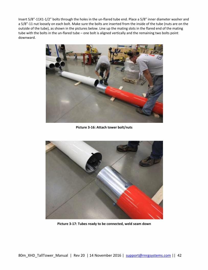
Insert 5/8”-11X1-1/2” bolts through the holes in the un-flared tube end. Place a 5/8” inner diameter washer and a 5/8”-11 nut loosely on each bolt. Make sure the bolts are inserted from the inside of the tube (nuts are on the outside of the tube), as shown in the pictures below. Line up the mating slots in the flared end of the mating tube with the bolts in the un-flared tube – one bolt is aligned vertically and the remaining two bolts point downward.
Picture 3-16: Attach tower bolt/nuts
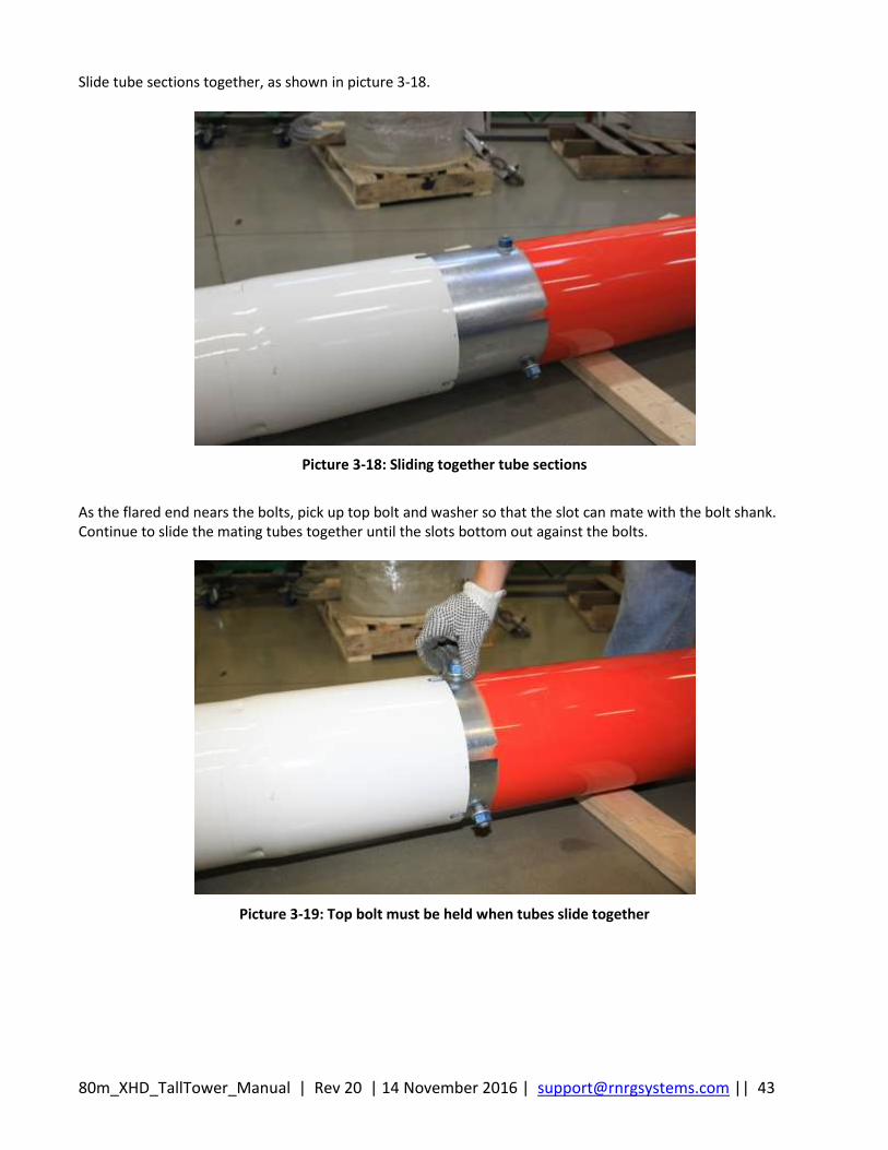
Picture 3-17: Tubes ready to be connected, weld seam down
80m_XHD_TallTower_Manual | Rev 20 | 14 November 2016 | [email protected] || 43
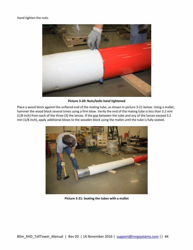
Slide tube sections together, as shown in picture 3-18.
Picture 3-18: Sliding together tube sections
As the flared end nears the bolts, pick up top bolt and washer so that the slot can mate with the bolt shank. Continue to slide the mating tubes together until the slots bottom out against the bolts.
Picture 3-19: Top bolt must be held when tubes slide together
80m_XHD_TallTower_Manual | Rev 20 | 14 November 2016 | [email protected] || 44
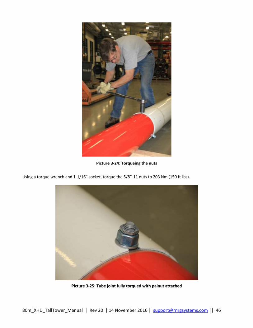
Hand tighten the nuts.
Picture 3-20: Nuts/bolts hand tightened
Place a wood block against the unflared end of the mating tube, as shown in picture 3-21 below. Using a mallet, hammer the wood block several times using a firm blow. Verify the end of the mating tube is less than 3.2 mm (1/8 inch) from each of the three (3) the lances. If the gap between the tube and any of the lances exceed 3.2 mm (1/8 inch), apply additional blows to the wooden block using the mallet until the tube is fully seated.
Picture 3-21: Seating the tubes with a mallet

80m_XHD_TallTower_Manual | Rev 20 | 14 November 2016 | [email protected] || 45
Picture 3-22: Tube lance and slot
A simple tool/jig can be made with a mark at 1/8” that can be inserted into the lance until it bottoms out on the inside tube. If your mark lines up perfect on all 3 lance holes, proceed to torque the 2 tubes together. Do not assemble the entire tower before torquring each joint. Torque each tube joint as you go.
Picture 3-23: Example of tool that can be used to confirm tubes are mated together fully
Flared end of tube
Slot and bolt hole
Mating tube
Lance
80m_XHD_TallTower_Manual | Rev 20 | 14 November 2016 | [email protected] || 46
Picture 3-24: Torqueing the nuts
Using a torque wrench and 1-1/16” socket, torque the 5/8”-11 nuts to 203 Nm (150 ft-lbs).
Picture 3-25: Tube joint fully torqued with palnut attached
80m_XHD_TallTower_Manual | Rev 20 | 14 November 2016 | [email protected] || 47
To provide anti-rotation to the bolt-nut assembly, screw on 5/8”-11 Palnuts on top of each 5/8”-11 nuts-shown in the picture above. Best practice is to fully seat the tubes together, double check through the lance that the joint is correct. Torque the nuts to 203 Nm (150 ft-lbs), then attach Palnuts. The Palnuts are a visual to remind you that the tube joint is correct and the nuts have been torqued.
Continue to assemble the tubes in the manner described above and place guy rings over the tubes according to the sequence outlined in Tables 3-1 and 3-2.
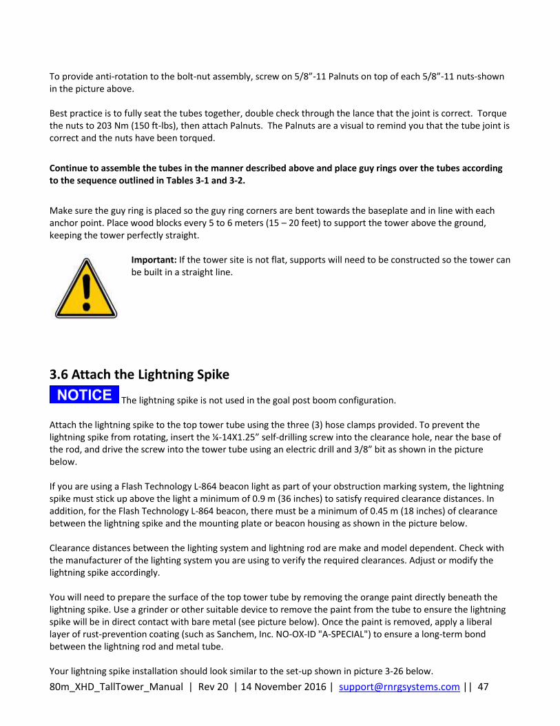
Make sure the guy ring is placed so the guy ring corners are bent towards the baseplate and in line with each anchor point. Place wood blocks every 5 to 6 meters (15 – 20 feet) to support the tower above the ground, keeping the tower perfectly straight.
Important: If the tower site is not flat, supports will need to be constructed so the tower can be built in a straight line.
3.6 Attach the Lightning Spike
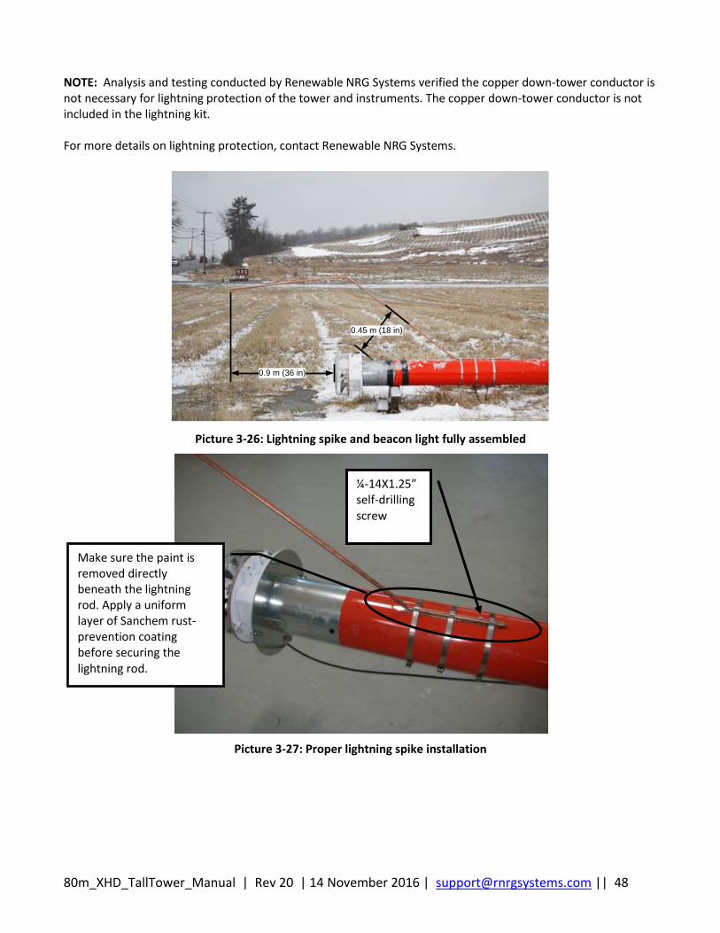
The lightning spike is not used in the goal post boom configuration. Attach the lightning spike to the top tower tube using the three (3) hose clamps provided. To prevent the lightning spike from rotating, insert the ¼-14X1.25” self-drilling screw into the clearance hole, near the base of the rod, and drive the screw into the tower tube using an electric drill and 3/8” bit as shown in the picture below. If you are using a Flash Technology L-864 beacon light as part of your obstruction marking system, the lightning spike must stick up above the light a minimum of 0.9 m (36 inches) to satisfy required clearance distances. In addition, for the Flash Technology L-864 beacon, there must be a minimum of 0.45 m (18 inches) of clearance between the lightning spike and the mounting plate or beacon housing as shown in the picture below. Clearance distances between the lighting system and lightning rod are make and model dependent. Check with the manufacturer of the lighting system you are using to verify the required clearances. Adjust or modify the lightning spike accordingly. You will need to prepare the surface of the top tower tube by removing the orange paint directly beneath the lightning spike. Use a grinder or other suitable device to remove the paint from the tube to ensure the lightning spike will be in direct contact with bare metal (see picture below). Once the paint is removed, apply a liberal layer of rust-prevention coating (such as Sanchem, Inc. NO-OX-ID "A-SPECIAL") to ensure a long-term bond between the lightning rod and metal tube. Your lightning spike installation should look similar to the set-up shown in picture 3-26 below.
80m_XHD_TallTower_Manual | Rev 20 | 14 November 2016 | [email protected] || 48
NOTE: Analysis and testing conducted by Renewable NRG Systems verified the copper down-tower conductor is not necessary for lightning protection of the tower and instruments. The copper down-tower conductor is not included in the lightning kit. For more details on lightning protection, contact Renewable NRG Systems.
0.45 m (18 in)
0.9 m (36 in)
Picture 3-26: Lightning spike and beacon light fully assembled
Picture 3-27: Proper lightning spike installation
Make sure the paint is removed directly beneath the lightning rod. Apply a uniform layer of Sanchem rust-prevention coating before securing the lightning rod.
¼-14X1.25” self-drilling screw
80m_XHD_TallTower_Manual | Rev 20 | 14 November 2016 | [email protected] || 49
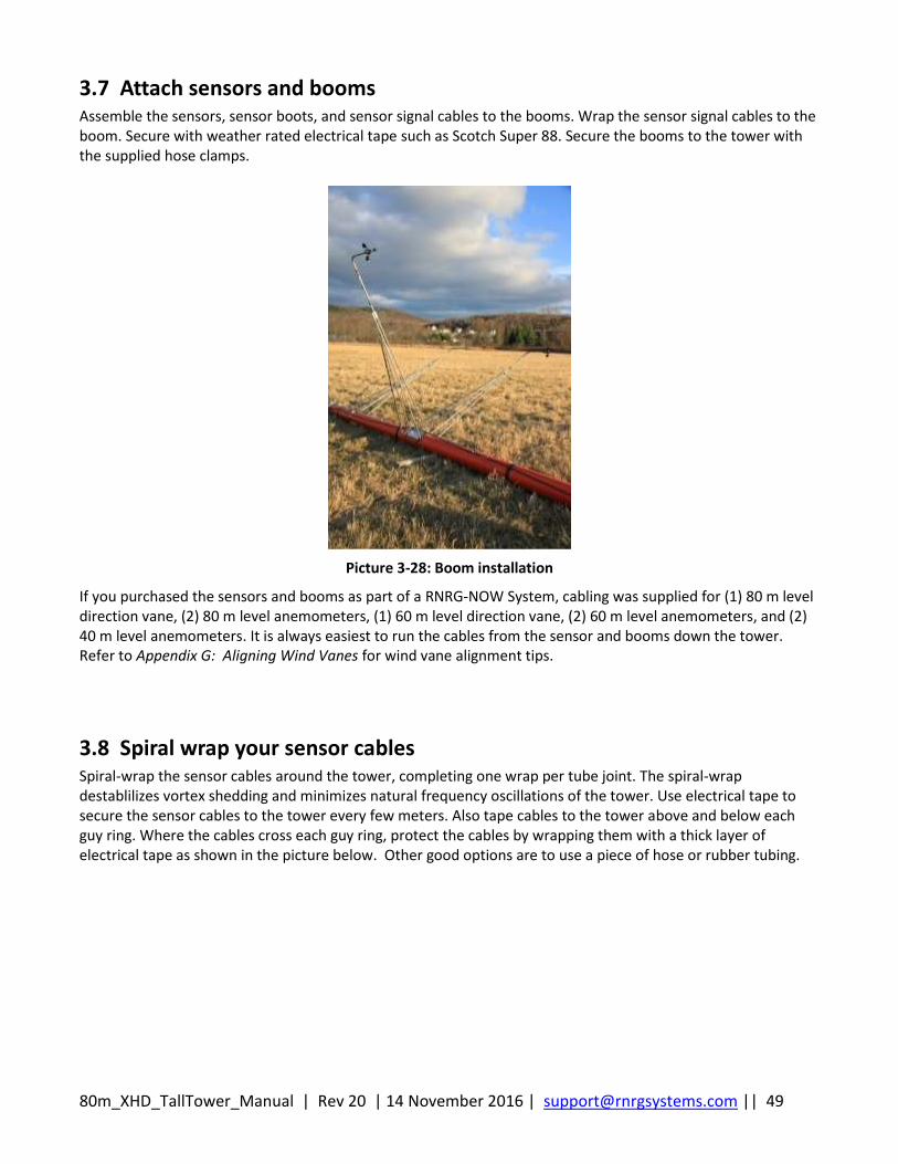
3.7 Attach sensors and booms Assemble the sensors, sensor boots, and sensor signal cables to the booms. Wrap the sensor signal cables to the boom. Secure with weather rated electrical tape such as Scotch Super 88. Secure the booms to the tower with the supplied hose clamps.
Picture 3-28: Boom installation
If you purchased the sensors and booms as part of a RNRG-NOW System, cabling was supplied for (1) 80 m level direction vane, (2) 80 m level anemometers, (1) 60 m level direction vane, (2) 60 m level anemometers, and (2) 40 m level anemometers. It is always easiest to run the cables from the sensor and booms down the tower. Refer to Appendix G: Aligning Wind Vanes for wind vane alignment tips.
3.8 Spiral wrap your sensor cables Spiral-wrap the sensor cables around the tower, completing one wrap per tube joint. The spiral-wrap destablilizes vortex shedding and minimizes natural frequency oscillations of the tower. Use electrical tape to secure the sensor cables to the tower every few meters. Also tape cables to the tower above and below each guy ring. Where the cables cross each guy ring, protect the cables by wrapping them with a thick layer of electrical tape as shown in the picture below. Other good options are to use a piece of hose or rubber tubing.

80m_XHD_TallTower_Manual | Rev 20 | 14 November 2016 | [email protected] || 50
Picture 3-29: Cable protection
3.9 Attach the Guy Wires
3.9.1 Organize and layout the lifters and guy wires
On the 80 m XHD TallTower, there are 32 guy wires and 8 lifter wires. Both the guy wires and lifters are color coded for the different levels to make this job easier. Be very careful to place all wires exactly as described in table 3-3 below to avoid having to disassemble and re-assemble. Sort out and identify the different length guy wires and match them with the appropriate guy ring level, then place them on the right-hand side of the tower at the corresponding guy level. Also, make sure the front guy wires are placed opposite of the quadrant occupying the lifter securing anchor. This will ensure the front guys wires do not get entangled with the lifters. Sort out and identify the different length lifter wires and match them with the appropriate guy ring level and place them on the left-hand side of the tower at the corresponding guy level.
Table 3-3: 80 m XHD TallTower Guy Levels
Guy Ring Level Label Text Label Color
1 Lowest Level 9.90 m (32.5 feet) Red
2 19.36 m (63.5 feet) White
3 28.82 m (94.6 feet) Black
4 38.28 m (125.6 feet) Yellow
5 47.74 m (156.6 feet) Blue
6 57.86 m (189.8 feet) Green
7 67.64 m (221.9 feet) Orange
8 Highest Level 77.42 m (254.0 feet) Purple
80m_XHD_TallTower_Manual | Rev 20 | 14 November 2016 | [email protected] || 51
To minimize the risk of entangling guy wires, it is recommended that back guy wires (the guy wires opposite the winch) are attached to their guy rings, rolled out, measured and marked, then secured to their anchors first (as described below in Back Guy Wire Marking Distance From Guy Level). Once the back guys are laid out and attached to the back anchors, prepare to attach the Back Stay Tensioning system. See Appendix E for assembly and procedure of Back Stay Tensioning System.
3.9.2 Guy wire roll out sequence
To ensure that no one needs to go under the tower during the lift process and no tangles occur, follow these steps when connecting guy wires:
- Shackle to tower, roll out and measured back guy wires, then attach to back anchors.
- Hook up Back Stay Tensioning System and attach to correct back guy wire (More information on the
Back Stay Tensioning System can be found in Appendix E).
- Shackle to tower, roll out and attach all side guy wires to side anchors. Take the time to roll out side guy
wires as straight as possible then attach to side anchors using 2-3 people to hand tighten. Fasten with
correct wire rope clip size.
- Shackle Lifter Wires to appropiate guy ring and leave rolled up on one side of tower.
- Shackle Front guy wires to appropriate guy ring and leave rolled up on opposite side of tower from lifter.
(The Lifter wire should be shackled closer to the tower, front guy wire on top of lifter away from tower)
See Picture 3-30 below.
- After the ginpole is constructed, lifters and front guy wires will be rolled out and attached.
3.9.3 Shackle lifter wires to the guy rings
Secure the lifter wires to the upper shackles containing the front guy wires on the top of the tower tube. Attachment of the 4th level (Yellow) lifter and front guy is shown in picture 3-30 below. After attaching the lifter wires to the guy ring, keep the lifter and front guy wire rolled up until the ginpole is constructed. This will keep the lifters and front guy wires organized until it is time to roll them out.
Picture 3-30: Front guy wire and lifter wire attachment
Front Guy Wire
Lifter Wire
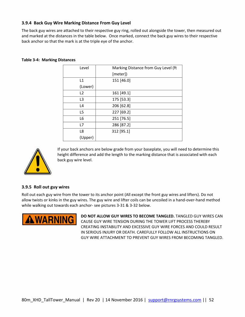
80m_XHD_TallTower_Manual | Rev 20 | 14 November 2016 | [email protected] || 52
3.9.4 Back Guy Wire Marking Distance From Guy Level
The back guy wires are attached to their respective guy ring, rolled out alongside the tower, then measured out and marked at the distances in the table below. Once marked, connect the back guy wires to their respective back anchor so that the mark is at the triple eye of the anchor.
Table 3-4: Marking Distances
Level Marking Distance from Guy Level (ft
[meter])
L1
(Lower)
151 [46.0]
L2 161 [49.1]
L3 175 [53.3]
L4 206 [62.8]
L5 227 [69.2]
L6 251 [76.5]
L7 286 [87.2]
L8
(Upper)
312 [95.1]
If your back anchors are below grade from your baseplate, you will need to determine this height difference and add the length to the marking distance that is associated with each back guy wire level.
3.9.5 Roll out guy wires
Roll out each guy wire from the tower to its anchor point (All except the front guy wires and lifters). Do not allow twists or kinks in the guy wires. The guy wire and lifter coils can be uncoiled in a hand-over-hand method while walking out towards each anchor- see pictures 3-31 & 3-32 below.
DO NOT ALLOW GUY WIRES TO BECOME TANGLED. TANGLED GUY WIRES CAN CAUSE GUY WIRE TENSION DURING THE TOWER LIFT PROCESS THEREBY CREATING INSTABILITY AND EXCESSIVE GUY WIRE FORCES AND COULD RESULT IN SERIOUS INJURY OR DEATH. CAREFULLY FOLLOW ALL INSTRUCTIONS ON GUY WIRE ATTACHMENT TO PREVENT GUY WIRES FROM BECOMING TANGLED.
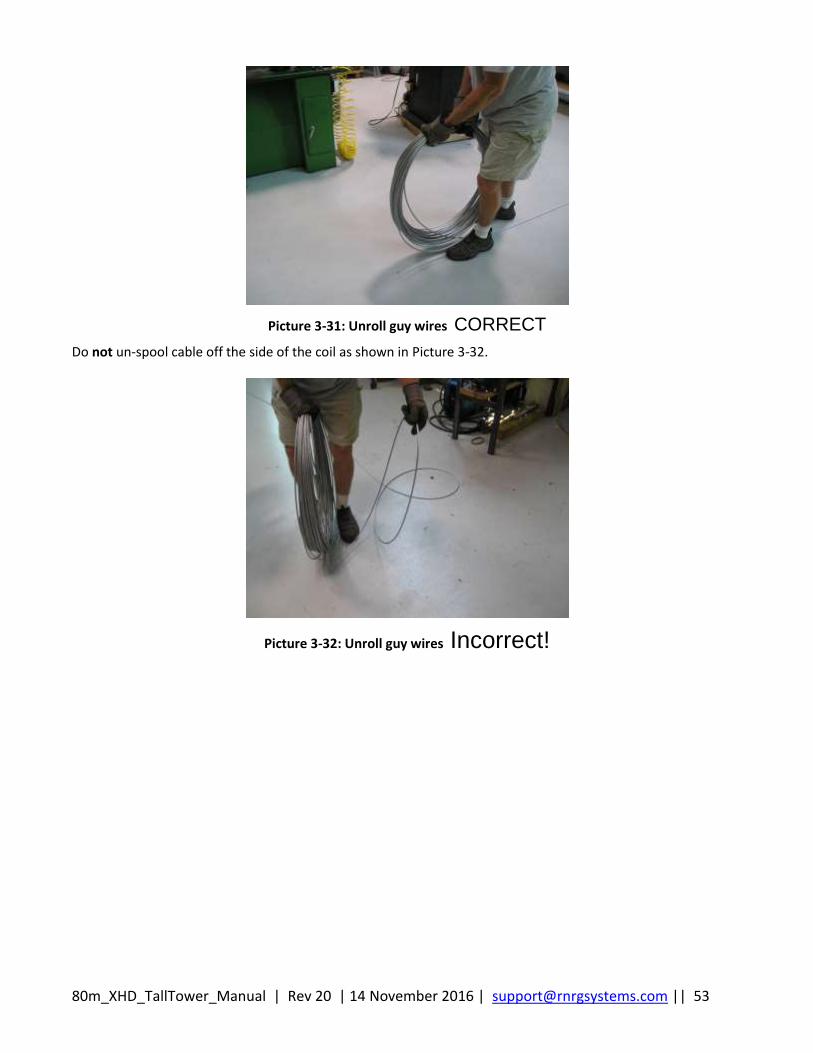
80m_XHD_TallTower_Manual | Rev 20 | 14 November 2016 | [email protected] || 53
Picture 3-31: Unroll guy wires CORRECT
Do not un-spool cable off the side of the coil as shown in Picture 3-32.
Picture 3-32: Unroll guy wires Incorrect!
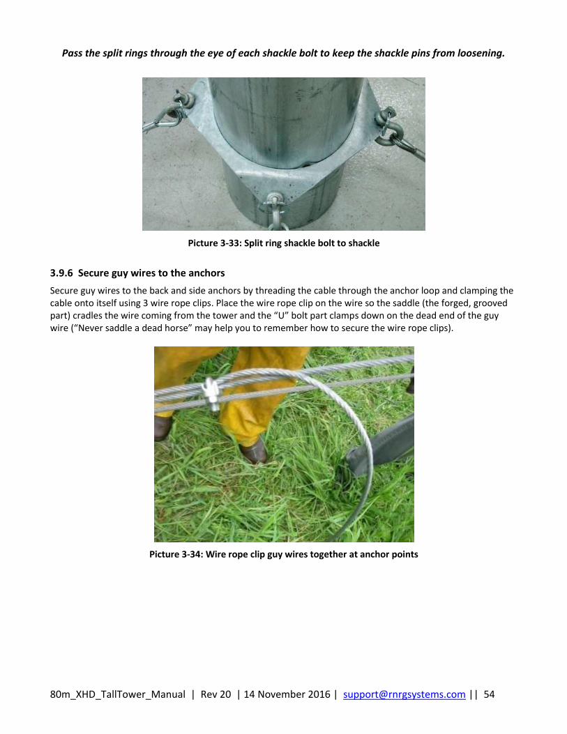
80m_XHD_TallTower_Manual | Rev 20 | 14 November 2016 | [email protected] || 54
Pass the split rings through the eye of each shackle bolt to keep the shackle pins from loosening.
Picture 3-33: Split ring shackle bolt to shackle
3.9.6 Secure guy wires to the anchors
Secure guy wires to the back and side anchors by threading the cable through the anchor loop and clamping the cable onto itself using 3 wire rope clips. Place the wire rope clip on the wire so the saddle (the forged, grooved part) cradles the wire coming from the tower and the “U” bolt part clamps down on the dead end of the guy wire (“Never saddle a dead horse” may help you to remember how to secure the wire rope clips).
Picture 3-34: Wire rope clip guy wires together at anchor points

80m_XHD_TallTower_Manual | Rev 20 | 14 November 2016 | [email protected] || 55
Picture 3-35: Wire rope clip guy wires together at anchor points
Leave a little slack in the guy wire, and tighten the wire rope clip nuts. Don’t tighten the wire rope clip nuts too tightly; you will need to adjust the guy length numerous times as the tower is erected.
3.10 Ginpole Assembly
3.10.1 Layout the ginpole tubes
Identify the ginpole, helper ginpole tubes, and hardware.
3.10.2 Attach the ginpole base tube to the baseplate
The ginpole base tube lays on top of the tower base tube. Place the ginpole base tube with the pivot pipe clearance hole between the baseplate’s vertical channels. Line up the holes in the ginpole base tube with the holes in the baseplate’s vertical channels and insert the pivot pipe through the baseplate clearance holes. Secure the pivot pipe with quick release pins.
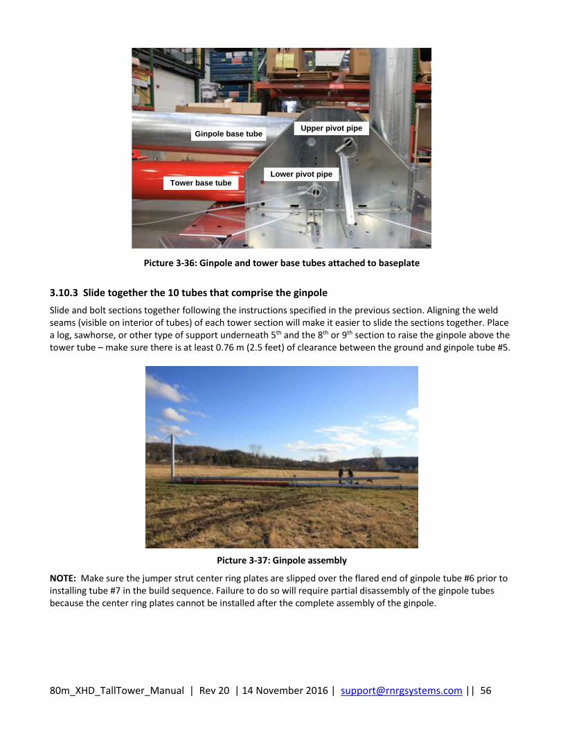
80m_XHD_TallTower_Manual | Rev 20 | 14 November 2016 | [email protected] || 56
Ginpole base tube
Tower base tubeLower pivot pipe
Upper pivot pipe
Picture 3-36: Ginpole and tower base tubes attached to baseplate
3.10.3 Slide together the 10 tubes that comprise the ginpole
Slide and bolt sections together following the instructions specified in the previous section. Aligning the weld seams (visible on interior of tubes) of each tower section will make it easier to slide the sections together. Place a log, sawhorse, or other type of support underneath 5th and the 8th or 9th section to raise the ginpole above the tower tube – make sure there is at least 0.76 m (2.5 feet) of clearance between the ground and ginpole tube #5.
Picture 3-37: Ginpole assembly
NOTE: Make sure the jumper strut center ring plates are slipped over the flared end of ginpole tube #6 prior to installing tube #7 in the build sequence. Failure to do so will require partial disassembly of the ginpole tubes because the center ring plates cannot be installed after the complete assembly of the ginpole.
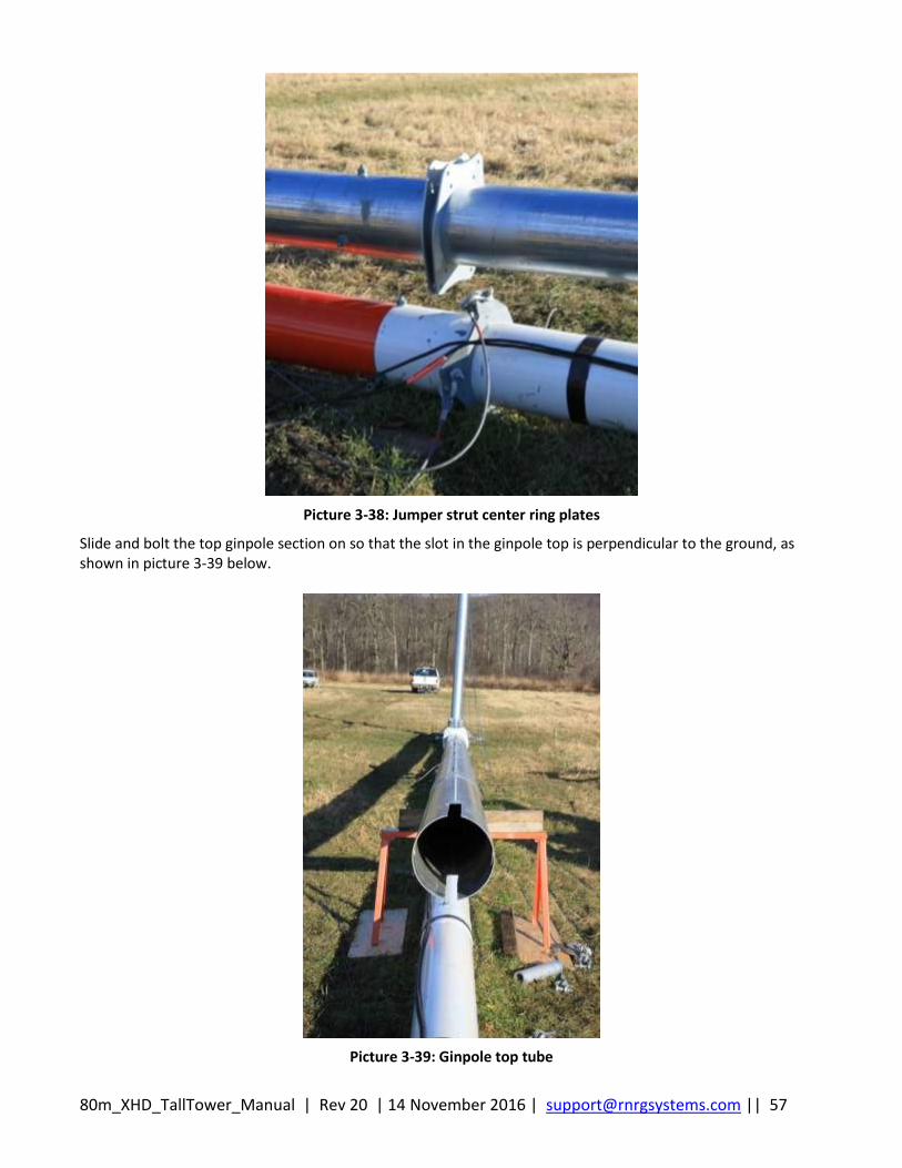
80m_XHD_TallTower_Manual | Rev 20 | 14 November 2016 | [email protected] || 57
Picture 3-38: Jumper strut center ring plates
Slide and bolt the top ginpole section on so that the slot in the ginpole top is perpendicular to the ground, as shown in picture 3-39 below.
Picture 3-39: Ginpole top tube
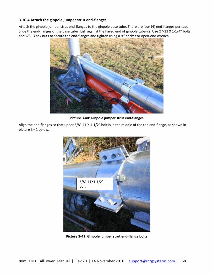
80m_XHD_TallTower_Manual | Rev 20 | 14 November 2016 | [email protected] || 58
3.10.4 Attach the ginpole jumper strut end-flanges
Attach the ginpole jumper strut end-flanges to the ginpole base tube. There are four (4) end-flanges per tube. Slide the end-flanges of the base tube flush against the flared end of ginpole tube #2. Use ½”-13 X 1-1/4” bolts and ½”-13 hex nuts to secure the end-flanges and tighten using a ¾” socket or open-end wrench.
Picture 3-40: Ginpole jumper strut end-flanges
Align the end-flanges so that upper 5/8”-11 X 1-1/2” bolt is in the middle of the top end-flange, as shown in picture 3-41 below.
Picture 3-41: Ginpole jumper strut end-flange bolts
5/8”-11X1-1/2” bolt
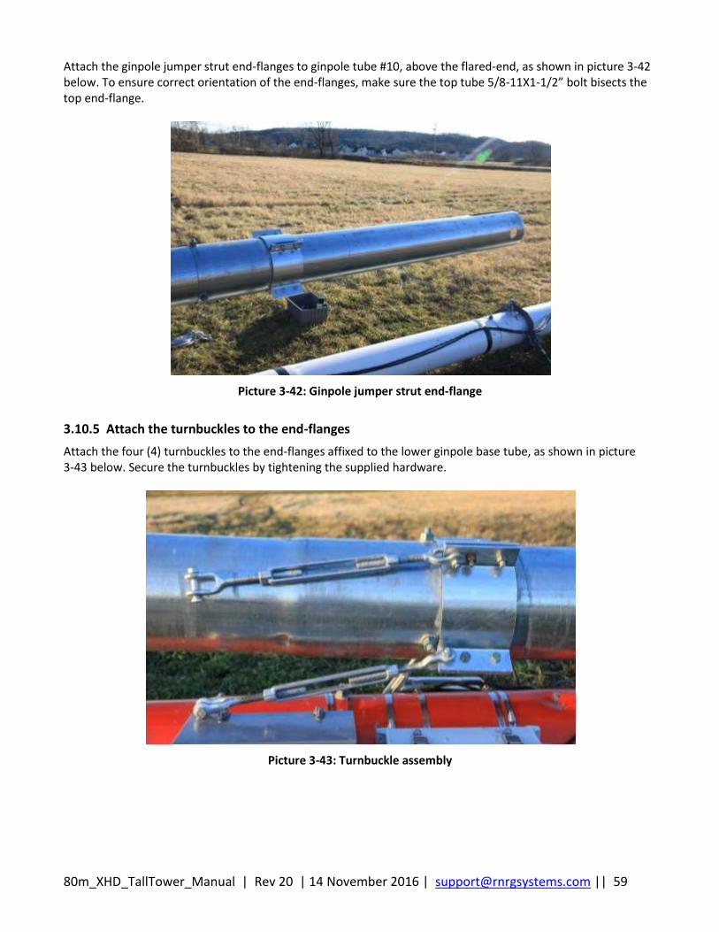
80m_XHD_TallTower_Manual | Rev 20 | 14 November 2016 | [email protected] || 59
Attach the ginpole jumper strut end-flanges to ginpole tube #10, above the flared-end, as shown in picture 3-42 below. To ensure correct orientation of the end-flanges, make sure the top tube 5/8-11X1-1/2” bolt bisects the top end-flange.
Picture 3-42: Ginpole jumper strut end-flange
3.10.5 Attach the turnbuckles to the end-flanges
Attach the four (4) turnbuckles to the end-flanges affixed to the lower ginpole base tube, as shown in picture 3-43 below. Secure the turnbuckles by tightening the supplied hardware.
Picture 3-43: Turnbuckle assembly
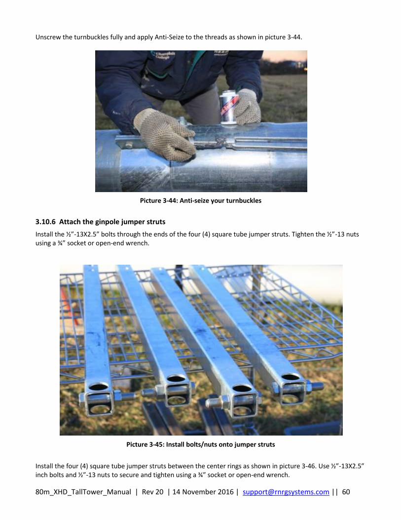
80m_XHD_TallTower_Manual | Rev 20 | 14 November 2016 | [email protected] || 60
Unscrew the turnbuckles fully and apply Anti-Seize to the threads as shown in picture 3-44.
Picture 3-44: Anti-seize your turnbuckles
3.10.6 Attach the ginpole jumper struts
Install the ½”-13X2.5” bolts through the ends of the four (4) square tube jumper struts. Tighten the ½”-13 nuts using a ¾” socket or open-end wrench.
Picture 3-45: Install bolts/nuts onto jumper struts
Install the four (4) square tube jumper struts between the center rings as shown in picture 3-46. Use ½”-13X2.5” inch bolts and ½”-13 nuts to secure and tighten using a ¾” socket or open-end wrench.
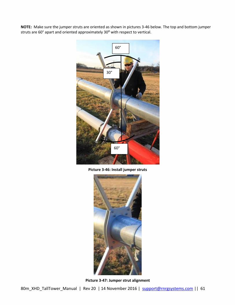
80m_XHD_TallTower_Manual | Rev 20 | 14 November 2016 | [email protected] || 61
NOTE: Make sure the jumper struts are oriented as shown in pictures 3-46 below. The top and bottom jumper struts are 60° apart and oriented approximately 30⁰ with respect to vertical.
Picture 3-46: Install jumper struts
Picture 3-47: Jumper strut alignment
60°
60°
30°
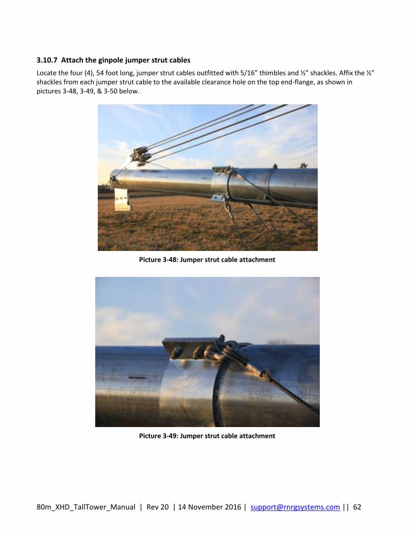
80m_XHD_TallTower_Manual | Rev 20 | 14 November 2016 | [email protected] || 62
3.10.7 Attach the ginpole jumper strut cables
Locate the four (4), 54 foot long, jumper strut cables outfitted with 5/16” thimbles and ½” shackles. Affix the ½” shackles from each jumper strut cable to the available clearance hole on the top end-flange, as shown in pictures 3-48, 3-49, & 3-50 below.
Picture 3-48: Jumper strut cable attachment
Picture 3-49: Jumper strut cable attachment
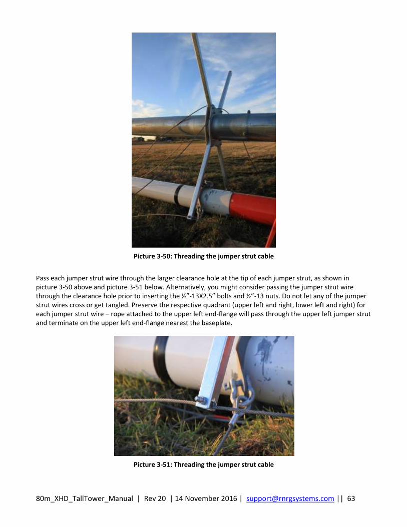
80m_XHD_TallTower_Manual | Rev 20 | 14 November 2016 | [email protected] || 63
Picture 3-50: Threading the jumper strut cable
Pass each jumper strut wire through the larger clearance hole at the tip of each jumper strut, as shown in picture 3-50 above and picture 3-51 below. Alternatively, you might consider passing the jumper strut wire through the clearance hole prior to inserting the ½”-13X2.5” bolts and ½”-13 nuts. Do not let any of the jumper strut wires cross or get tangled. Preserve the respective quadrant (upper left and right, lower left and right) for each jumper strut wire – rope attached to the upper left end-flange will pass through the upper left jumper strut and terminate on the upper left end-flange nearest the baseplate.
Picture 3-51: Threading the jumper strut cable
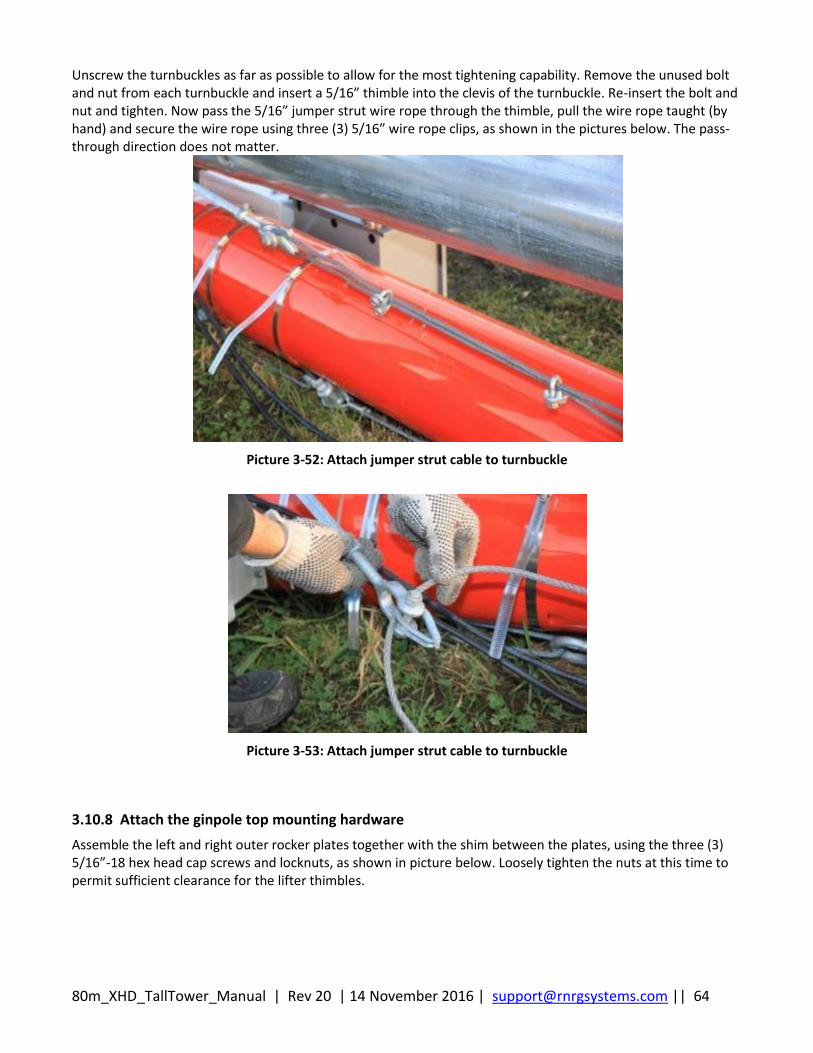
80m_XHD_TallTower_Manual | Rev 20 | 14 November 2016 | [email protected] || 64
Unscrew the turnbuckles as far as possible to allow for the most tightening capability. Remove the unused bolt and nut from each turnbuckle and insert a 5/16” thimble into the clevis of the turnbuckle. Re-insert the bolt and nut and tighten. Now pass the 5/16” jumper strut wire rope through the thimble, pull the wire rope taught (by hand) and secure the wire rope using three (3) 5/16” wire rope clips, as shown in the pictures below. The pass-through direction does not matter.
Picture 3-52: Attach jumper strut cable to turnbuckle
Picture 3-53: Attach jumper strut cable to turnbuckle
3.10.8 Attach the ginpole top mounting hardware
Assemble the left and right outer rocker plates together with the shim between the plates, using the three (3) 5/16”-18 hex head cap screws and locknuts, as shown in picture below. Loosely tighten the nuts at this time to permit sufficient clearance for the lifter thimbles.
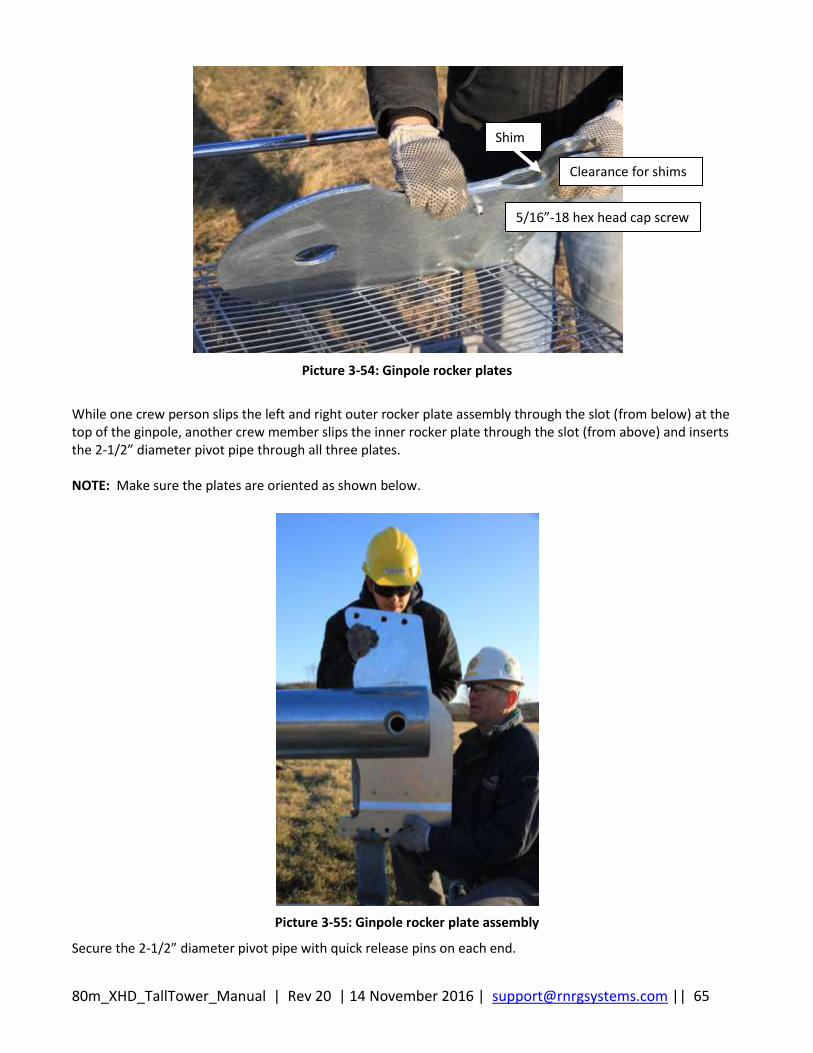
80m_XHD_TallTower_Manual | Rev 20 | 14 November 2016 | [email protected] || 65
Picture 3-54: Ginpole rocker plates
While one crew person slips the left and right outer rocker plate assembly through the slot (from below) at the top of the ginpole, another crew member slips the inner rocker plate through the slot (from above) and inserts the 2-1/2” diameter pivot pipe through all three plates. NOTE: Make sure the plates are oriented as shown below.
Picture 3-55: Ginpole rocker plate assembly
Secure the 2-1/2” diameter pivot pipe with quick release pins on each end.
Shim
Clearance for shims
5/16”-18 hex head cap screw
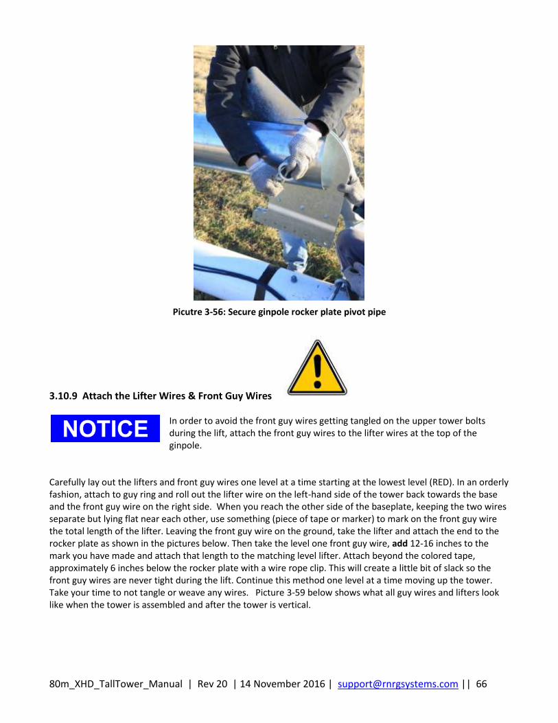
80m_XHD_TallTower_Manual | Rev 20 | 14 November 2016 | [email protected] || 66
Picutre 3-56: Secure ginpole rocker plate pivot pipe
3.10.9 Attach the Lifter Wires & Front Guy Wires
Carefully lay out the lifters and front guy wires one level at a time starting at the lowest level (RED). In an orderly fashion, attach to guy ring and roll out the lifter wire on the left-hand side of the tower back towards the base and the front guy wire on the right side. When you reach the other side of the baseplate, keeping the two wires separate but lying flat near each other, use something (piece of tape or marker) to mark on the front guy wire the total length of the lifter. Leaving the front guy wire on the ground, take the lifter and attach the end to the rocker plate as shown in the pictures below. Then take the level one front guy wire, add 12-16 inches to the mark you have made and attach that length to the matching level lifter. Attach beyond the colored tape, approximately 6 inches below the rocker plate with a wire rope clip. This will create a little bit of slack so the front guy wires are never tight during the lift. Continue this method one level at a time moving up the tower. Take your time to not tangle or weave any wires. Picture 3-59 below shows what all guy wires and lifters look like when the tower is assembled and after the tower is vertical.
In order to avoid the front guy wires getting tangled on the upper tower bolts during the lift, attach the front guy wires to the lifter wires at the top of the ginpole.
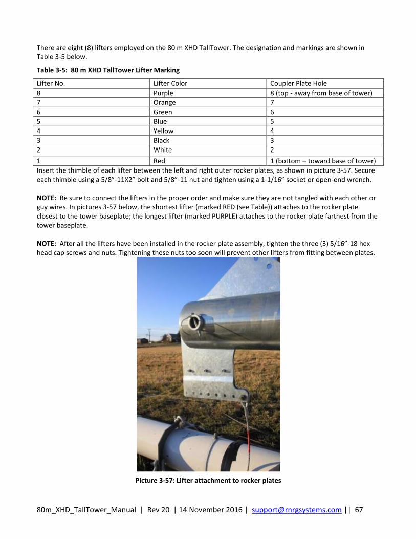
80m_XHD_TallTower_Manual | Rev 20 | 14 November 2016 | [email protected] || 67
There are eight (8) lifters employed on the 80 m XHD TallTower. The designation and markings are shown in Table 3-5 below.
Table 3-5: 80 m XHD TallTower Lifter Marking
Lifter No. Lifter Color Coupler Plate Hole
8 Purple 8 (top - away from base of tower)
7 Orange 7
6 Green 6
5 Blue 5
4 Yellow 4
3 Black 3
2 White 2
1 Red 1 (bottom – toward base of tower)
Insert the thimble of each lifter between the left and right outer rocker plates, as shown in picture 3-57. Secure each thimble using a 5/8”-11X2” bolt and 5/8”-11 nut and tighten using a 1-1/16” socket or open-end wrench. NOTE: Be sure to connect the lifters in the proper order and make sure they are not tangled with each other or guy wires. In pictures 3-57 below, the shortest lifter (marked RED (see Table)) attaches to the rocker plate closest to the tower baseplate; the longest lifter (marked PURPLE) attaches to the rocker plate farthest from the tower baseplate. NOTE: After all the lifters have been installed in the rocker plate assembly, tighten the three (3) 5/16”-18 hex head cap screws and nuts. Tightening these nuts too soon will prevent other lifters from fitting between plates.
Picture 3-57: Lifter attachment to rocker plates
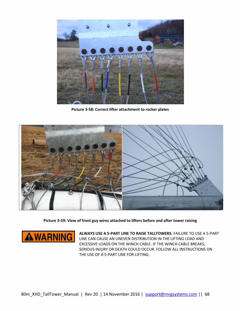
80m_XHD_TallTower_Manual | Rev 20 | 14 November 2016 | [email protected] || 68
Picture 3-58: Correct lifter attachment to rocker plates
Picture 3-59: View of front guy wires attached to lifters before and after tower raising
ALWAYS USE A 5-PART LINE TO RAISE TALLTOWERS. FAILURE TO USE A 5-PART LINE CAN CAUSE AN UNEVEN DISTRIBUTION IN THE LIFTING LOAD AND EXCESSIVE LOADS ON THE WINCH CABLE. IF THE WINCH CABLE BREAKS, SERIOUS INJURY OR DEATH COULD OCCUR. FOLLOW ALL INSTRUCTIONS ON THE USE OF A 5-PART LINE FOR LIFTING.
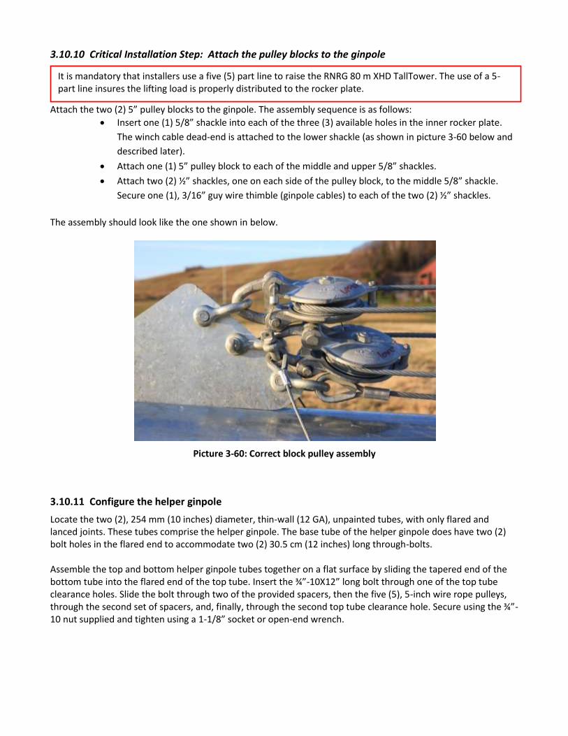
3.10.10 Critical Installation Step: Attach the pulley blocks to the ginpole
Attach the two (2) 5” pulley blocks to the ginpole. The assembly sequence is as follows:
Insert one (1) 5/8” shackle into each of the three (3) available holes in the inner rocker plate.
The winch cable dead-end is attached to the lower shackle (as shown in picture 3-60 below and
described later).
Attach one (1) 5” pulley block to each of the middle and upper 5/8” shackles.
Attach two (2) ½” shackles, one on each side of the pulley block, to the middle 5/8” shackle.
Secure one (1), 3/16” guy wire thimble (ginpole cables) to each of the two (2) ½” shackles.
The assembly should look like the one shown in below.
Picture 3-60: Correct block pulley assembly
3.10.11 Configure the helper ginpole
Locate the two (2), 254 mm (10 inches) diameter, thin-wall (12 GA), unpainted tubes, with only flared and lanced joints. These tubes comprise the helper ginpole. The base tube of the helper ginpole does have two (2) bolt holes in the flared end to accommodate two (2) 30.5 cm (12 inches) long through-bolts. Assemble the top and bottom helper ginpole tubes together on a flat surface by sliding the tapered end of the bottom tube into the flared end of the top tube. Insert the ¾”-10X12” long bolt through one of the top tube clearance holes. Slide the bolt through two of the provided spacers, then the five (5), 5-inch wire rope pulleys, through the second set of spacers, and, finally, through the second top tube clearance hole. Secure using the ¾”-10 nut supplied and tighten using a 1-1/8” socket or open-end wrench.
It is mandatory that installers use a five (5) part line to raise the RNRG 80 m XHD TallTower. The use of a 5-part line insures the lifting load is properly distributed to the rocker plate.

80m_XHD_TallTower_Manual | Rev 20 | 14 November 2016 | [email protected] || 70
Picture 3-61: Helper ginpole pulleys with winch cable fully reeved
Tilt-up the helper ginpole assembly, making sure the (unused) clearance holes are on the bottom and the V-belt pulleys point to the sky. Walk the helper ginpole between the uprights of the baseplate behind the tower and ginpole base tubes, aligning the clearance holes of the tubes and uprights. Insert the two (2) ¾”-10X12” bolts through the holes on the helper ginpole tube and secure with ¾”-10 nuts. Tighten the nuts using a 1-1/8” socket or open-end wrench.
Picture 3-62: Attach helper ginpole
5-inch wire rope pulleys
¾”-10X12” bolt and nut
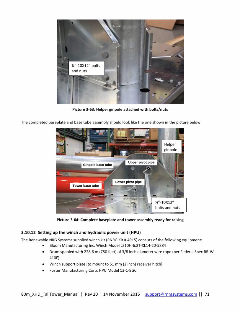
80m_XHD_TallTower_Manual | Rev 20 | 14 November 2016 | [email protected] || 71
Picture 3-63: Helper ginpole attached with bolts/nuts
The completed baseplate and base tube assembly should look like the one shown in the picture below.
Ginpole base tube
Tower base tubeLower pivot pipe
Upper pivot pipe
Picture 3-64: Complete baseplate and tower assembly ready for raising
3.10.12 Setting up the winch and hydraulic power unit (HPU)
The Renewable NRG Systems supplied winch kit (RNRG Kit # 4915) consists of the following equipment:
Bloom Manufacturing Inc. Winch Model LS10H-6.2T-XL14-20-5884
Drum spooled with 228.6 m (750 feet) of 3/8 inch diameter wire rope (per Federal Spec RR-W-
410F)
Winch support plate [to mount to 51 mm (2 inch) receiver hitch]
Foster Manufacturing Corp. HPU Model 13-1-8GC
Helper ginpole
¾”-10X12” bolts and nuts
¾”-10X12” bolts and nuts
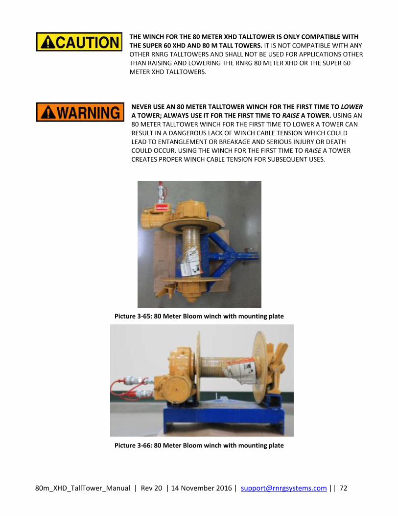
80m_XHD_TallTower_Manual | Rev 20 | 14 November 2016 | [email protected] || 72
THE WINCH FOR THE 80 METER XHD TALLTOWER IS ONLY COMPATIBLE WITH THE SUPER 60 XHD AND 80 M TALL TOWERS. IT IS NOT COMPATIBLE WITH ANY OTHER RNRG TALLTOWERS AND SHALL NOT BE USED FOR APPLICATIONS OTHER THAN RAISING AND LOWERING THE RNRG 80 METER XHD OR THE SUPER 60 METER XHD TALLTOWERS.
NEVER USE AN 80 METER TALLTOWER WINCH FOR THE FIRST TIME TO LOWER A TOWER; ALWAYS USE IT FOR THE FIRST TIME TO RAISE A TOWER. USING AN 80 METER TALLTOWER WINCH FOR THE FIRST TIME TO LOWER A TOWER CAN RESULT IN A DANGEROUS LACK OF WINCH CABLE TENSION WHICH COULD LEAD TO ENTANGLEMENT OR BREAKAGE AND SERIOUS INJURY OR DEATH COULD OCCUR. USING THE WINCH FOR THE FIRST TIME TO RAISE A TOWER CREATES PROPER WINCH CABLE TENSION FOR SUBSEQUENT USES.
Picture 3-65: 80 Meter Bloom winch with mounting plate
Picture 3-66: 80 Meter Bloom winch with mounting plate
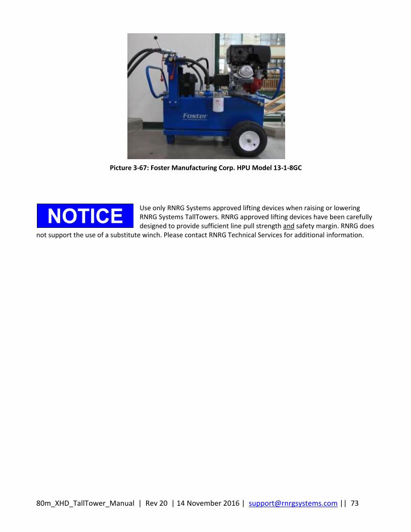
80m_XHD_TallTower_Manual | Rev 20 | 14 November 2016 | [email protected] || 73
Picture 3-67: Foster Manufacturing Corp. HPU Model 13-1-8GC
Use only RNRG Systems approved lifting devices when raising or lowering RNRG Systems TallTowers. RNRG approved lifting devices have been carefully designed to provide sufficient line pull strength and safety margin. RNRG does
not support the use of a substitute winch. Please contact RNRG Technical Services for additional information.
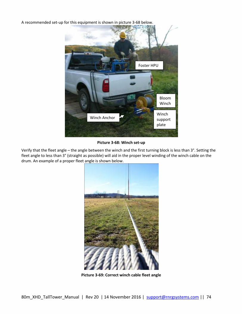
80m_XHD_TallTower_Manual | Rev 20 | 14 November 2016 | [email protected] || 74
A recommended set-up for this equipment is shown in picture 3-68 below.
Picture 3-68: Winch set-up
Verify that the fleet angle – the angle between the winch and the first turning block is less than 3°. Setting the fleet angle to less than 3° (straight as possible) will aid in the proper level winding of the winch cable on the drum. An example of a proper fleet angle is shown below.
Picture 3-69: Correct winch cable fleet angle
Foster HPU
Bloom Winch
Winch Anchor Winch support plate
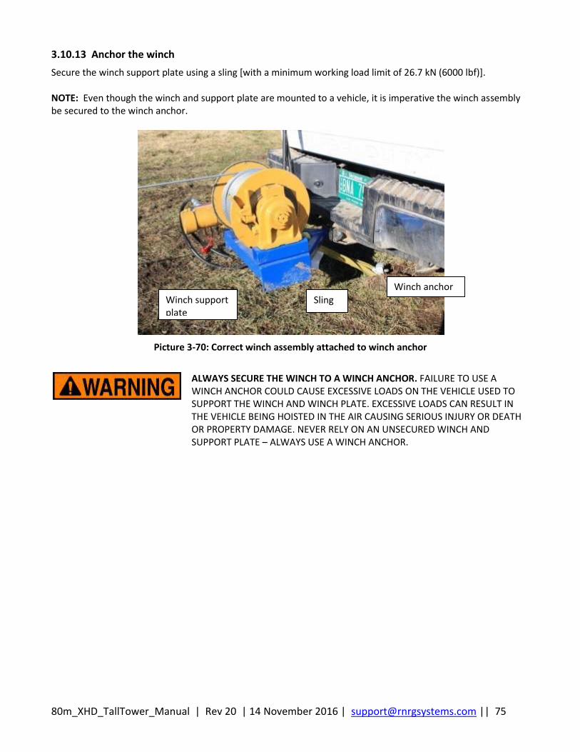
80m_XHD_TallTower_Manual | Rev 20 | 14 November 2016 | [email protected] || 75
3.10.13 Anchor the winch
Secure the winch support plate using a sling [with a minimum working load limit of 26.7 kN (6000 lbf)]. NOTE: Even though the winch and support plate are mounted to a vehicle, it is imperative the winch assembly be secured to the winch anchor.
Picture 3-70: Correct winch assembly attached to winch anchor
ALWAYS SECURE THE WINCH TO A WINCH ANCHOR. FAILURE TO USE A WINCH ANCHOR COULD CAUSE EXCESSIVE LOADS ON THE VEHICLE USED TO SUPPORT THE WINCH AND WINCH PLATE. EXCESSIVE LOADS CAN RESULT IN THE VEHICLE BEING HOISTED IN THE AIR CAUSING SERIOUS INJURY OR DEATH OR PROPERTY DAMAGE. NEVER RELY ON AN UNSECURED WINCH AND SUPPORT PLATE – ALWAYS USE A WINCH ANCHOR.
Winch support plate
Sling
Winch anchor
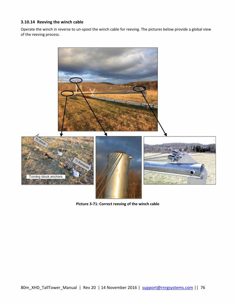
80m_XHD_TallTower_Manual | Rev 20 | 14 November 2016 | [email protected] || 76
3.10.14 Reeving the winch cable
Operate the winch in reverse to un-spool the winch cable for reeving. The pictures below provide a global view of the reeving process.
Picture 3-71: Correct reeving of the winch cable
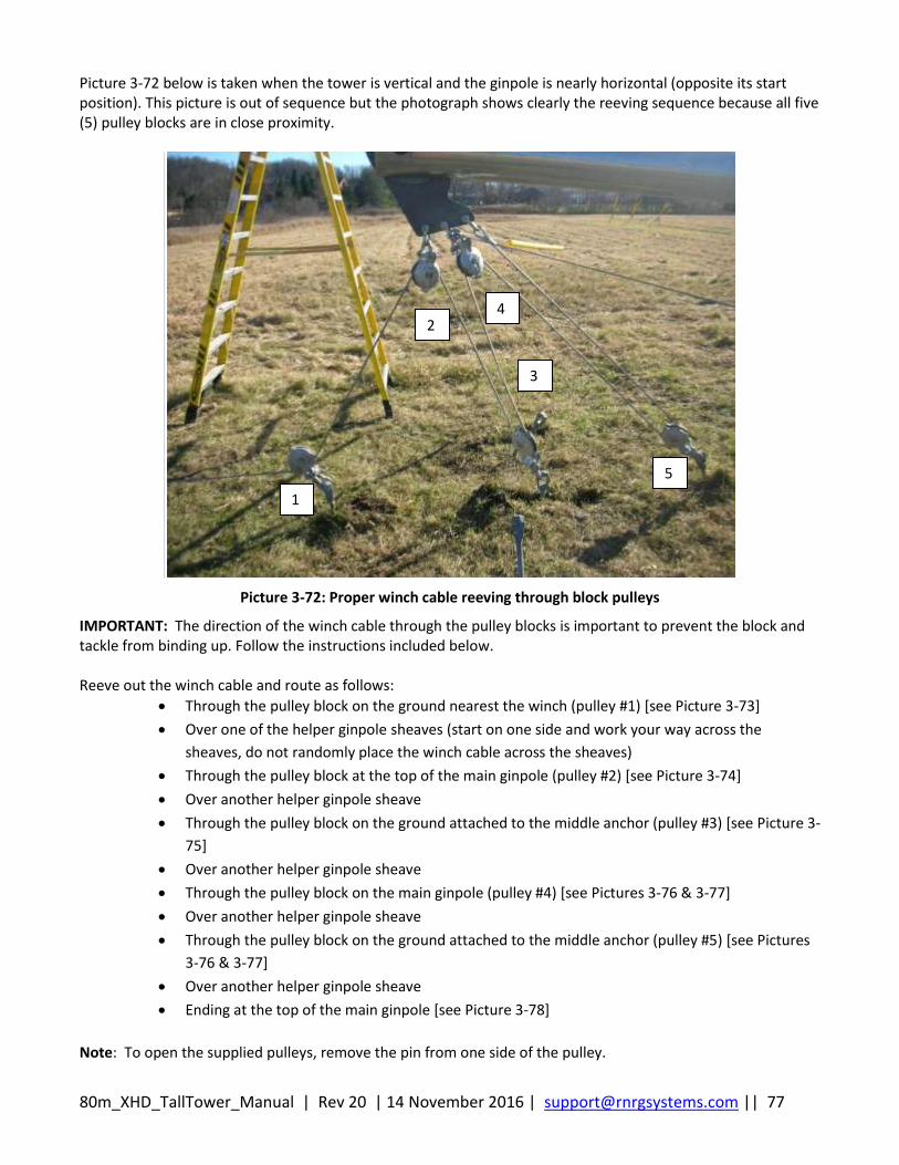
80m_XHD_TallTower_Manual | Rev 20 | 14 November 2016 | [email protected] || 77
Picture 3-72 below is taken when the tower is vertical and the ginpole is nearly horizontal (opposite its start position). This picture is out of sequence but the photograph shows clearly the reeving sequence because all five (5) pulley blocks are in close proximity.
Picture 3-72: Proper winch cable reeving through block pulleys
IMPORTANT: The direction of the winch cable through the pulley blocks is important to prevent the block and tackle from binding up. Follow the instructions included below. Reeve out the winch cable and route as follows:
Through the pulley block on the ground nearest the winch (pulley #1) [see Picture 3-73]
Over one of the helper ginpole sheaves (start on one side and work your way across the
sheaves, do not randomly place the winch cable across the sheaves)
Through the pulley block at the top of the main ginpole (pulley #2) [see Picture 3-74]
Over another helper ginpole sheave
Through the pulley block on the ground attached to the middle anchor (pulley #3) [see Picture 3-
75]
Over another helper ginpole sheave
Through the pulley block on the main ginpole (pulley #4) [see Pictures 3-76 & 3-77]
Over another helper ginpole sheave
Through the pulley block on the ground attached to the middle anchor (pulley #5) [see Pictures
3-76 & 3-77]
Over another helper ginpole sheave
Ending at the top of the main ginpole [see Picture 3-78]
Note: To open the supplied pulleys, remove the pin from one side of the pulley.
1
2
3
4
5
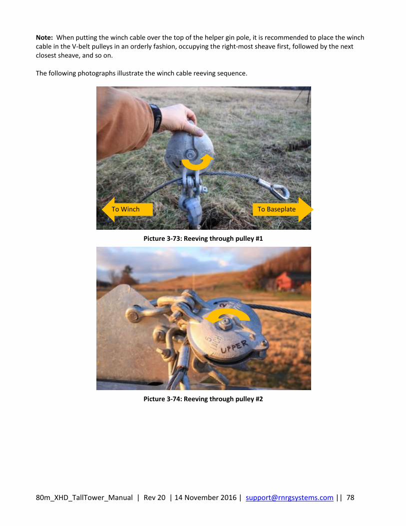
80m_XHD_TallTower_Manual | Rev 20 | 14 November 2016 | [email protected] || 78
Note: When putting the winch cable over the top of the helper gin pole, it is recommended to place the winch cable in the V-belt pulleys in an orderly fashion, occupying the right-most sheave first, followed by the next closest sheave, and so on. The following photographs illustrate the winch cable reeving sequence.
Picture 3-73: Reeving through pulley #1
Picture 3-74: Reeving through pulley #2
To Winch To Baseplate
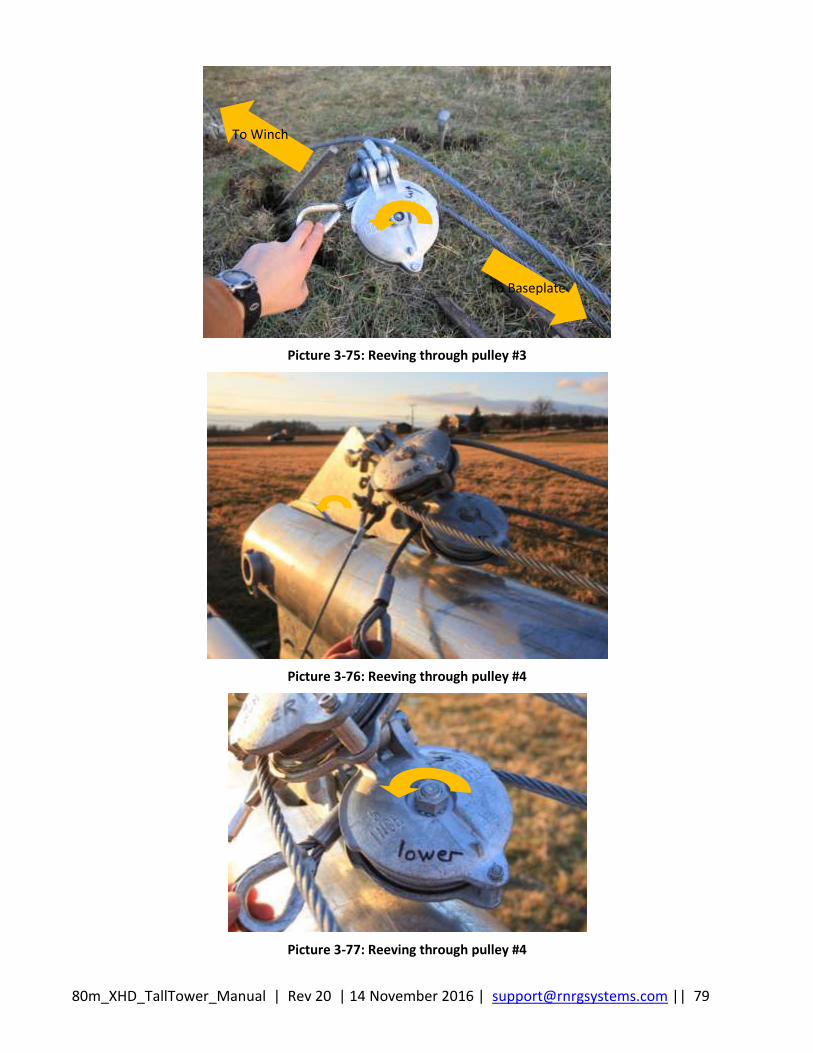
80m_XHD_TallTower_Manual | Rev 20 | 14 November 2016 | [email protected] || 79
Picture 3-75: Reeving through pulley #3
Picture 3-76: Reeving through pulley #4
Picture 3-77: Reeving through pulley #4
To Winch
To Baseplate
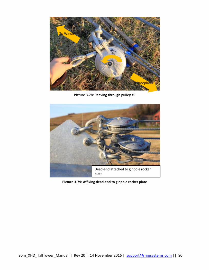
80m_XHD_TallTower_Manual | Rev 20 | 14 November 2016 | [email protected] || 80
Picture 3-78: Reeving through pulley #5
Picture 3-79: Affixing dead-end to ginpole rocker plate
Dead-end attached to ginpole rocker plate
To Winch
To Baseplate
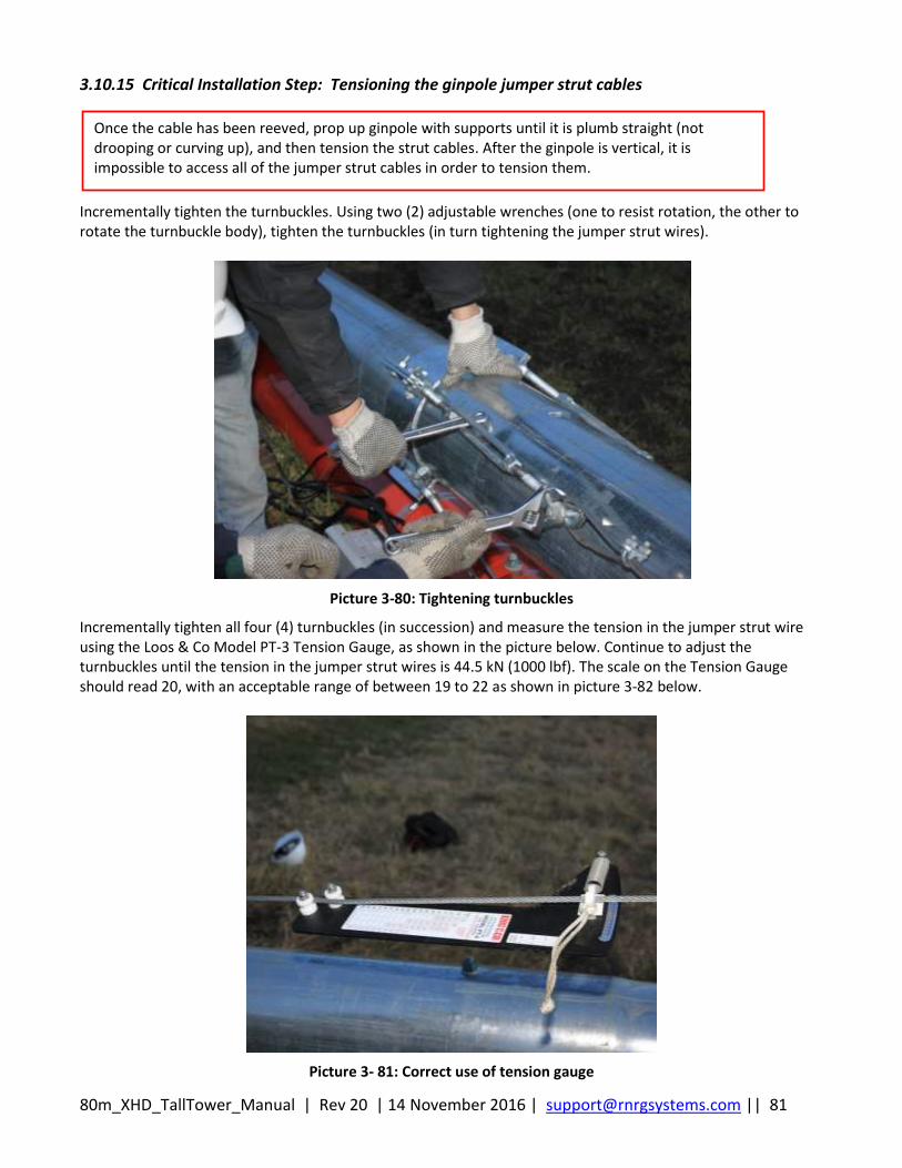
80m_XHD_TallTower_Manual | Rev 20 | 14 November 2016 | [email protected] || 81
3.10.15 Critical Installation Step: Tensioning the ginpole jumper strut cables
Incrementally tighten the turnbuckles. Using two (2) adjustable wrenches (one to resist rotation, the other to rotate the turnbuckle body), tighten the turnbuckles (in turn tightening the jumper strut wires).
Picture 3-80: Tightening turnbuckles
Incrementally tighten all four (4) turnbuckles (in succession) and measure the tension in the jumper strut wire using the Loos & Co Model PT-3 Tension Gauge, as shown in the picture below. Continue to adjust the turnbuckles until the tension in the jumper strut wires is 44.5 kN (1000 lbf). The scale on the Tension Gauge should read 20, with an acceptable range of between 19 to 22 as shown in picture 3-82 below.
Picture 3- 81: Correct use of tension gauge
Once the cable has been reeved, prop up ginpole with supports until it is plumb straight (not drooping or curving up), and then tension the strut cables. After the ginpole is vertical, it is impossible to access all of the jumper strut cables in order to tension them.
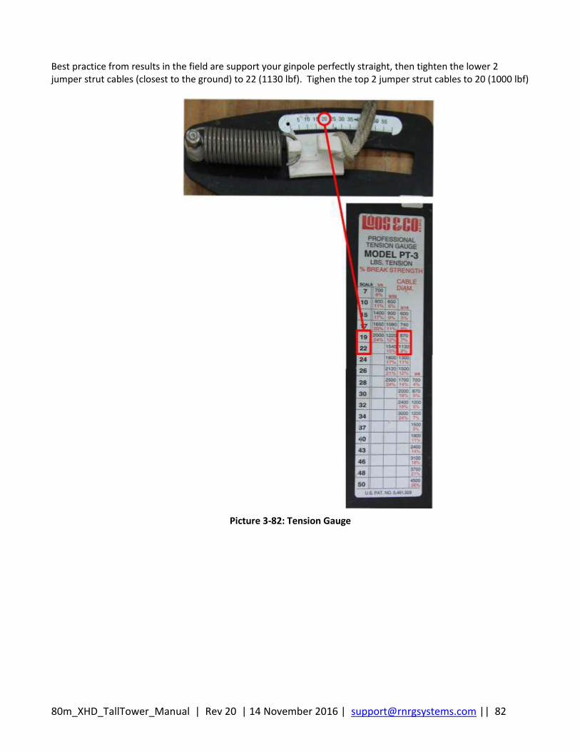
80m_XHD_TallTower_Manual | Rev 20 | 14 November 2016 | [email protected] || 82
Best practice from results in the field are support your ginpole perfectly straight, then tighten the lower 2 jumper strut cables (closest to the ground) to 22 (1130 lbf). Tighen the top 2 jumper strut cables to 20 (1000 lbf)
Picture 3-82: Tension Gauge
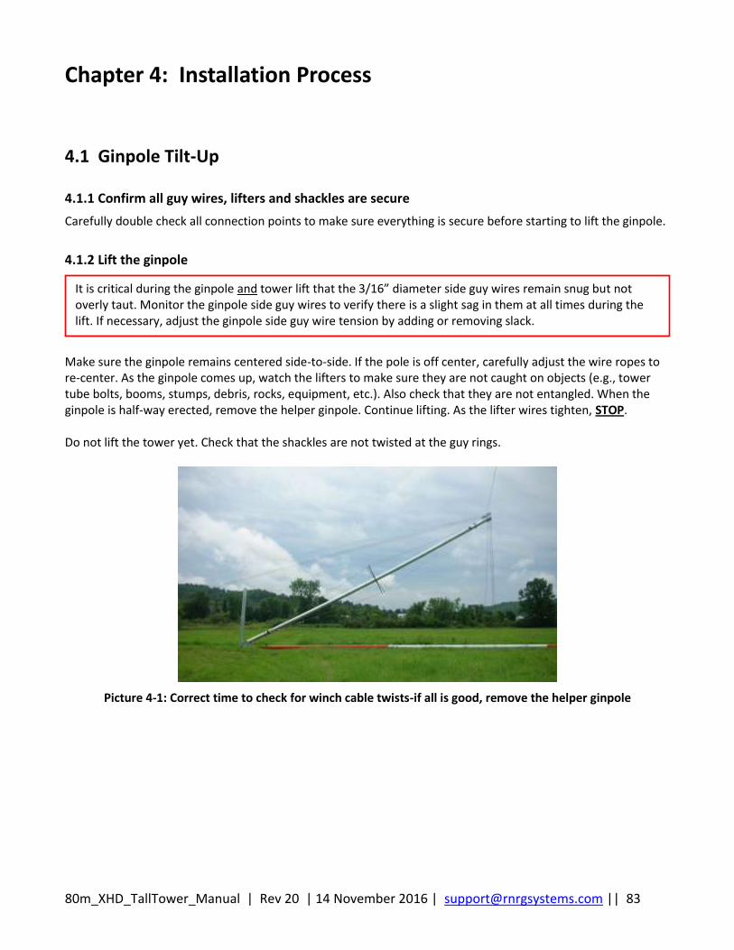
80m_XHD_TallTower_Manual | Rev 20 | 14 November 2016 | [email protected] || 83
Chapter 4: Installation Process
4.1 Ginpole Tilt-Up
4.1.1 Confirm all guy wires, lifters and shackles are secure
Carefully double check all connection points to make sure everything is secure before starting to lift the ginpole.
4.1.2 Lift the ginpole
Make sure the ginpole remains centered side-to-side. If the pole is off center, carefully adjust the wire ropes to re-center. As the ginpole comes up, watch the lifters to make sure they are not caught on objects (e.g., tower tube bolts, booms, stumps, debris, rocks, equipment, etc.). Also check that they are not entangled. When the ginpole is half-way erected, remove the helper ginpole. Continue lifting. As the lifter wires tighten, STOP. Do not lift the tower yet. Check that the shackles are not twisted at the guy rings.
Picture 4-1: Correct time to check for winch cable twists-if all is good, remove the helper ginpole
It is critical during the ginpole and tower lift that the 3/16” diameter side guy wires remain snug but not overly taut. Monitor the ginpole side guy wires to verify there is a slight sag in them at all times during the lift. If necessary, adjust the ginpole side guy wire tension by adding or removing slack.
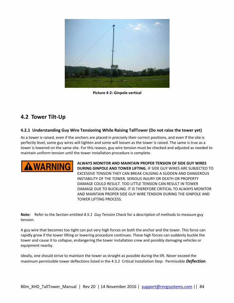
80m_XHD_TallTower_Manual | Rev 20 | 14 November 2016 | [email protected] || 84
Picture 4-2: Ginpole vertical
4.2 Tower Tilt-Up
4.2.1 Understanding Guy Wire Tensioning While Raising TallTower (Do not raise the tower yet)
As a tower is raised, even if the anchors are placed in precisely their correct positions, and even if the site is perfectly level, some guy wires will tighten and some will loosen as the tower is raised. The same is true as a tower is lowered on the same site. For this reason, guy wire tension must be checked and adjusted as needed to maintain uniform tension until the tower installation procedure is complete.
ALWAYS MONITOR AND MAINTAIN PROPER TENSION OF SIDE GUY WIRES DURING GINPOLE AND TOWER LIFTING. IF SIDE GUY WIRES ARE SUBJECTED TO EXCESSIVE TENSION THEY CAN BREAK CAUSING A SUDDEN AND DANGEROUS INSTABILITY OF THE TOWER. SERIOUS INJURY OR DEATH OR PROPERTY DAMAGE COULD RESULT. TOO LITTLE TENSION CAN RESULT IN TOWER DAMAGE DUE TO BUCKLING. IT IS THEREFORE CRITICAL TO ALWAYS MONITOR AND MAINTAIN PROPER SIDE GUY WIRE TENSION DURING THE GINPOLE AND TOWER LIFTING PROCESS.
Note: Refer to the Section entitled 4.5.1 Guy Tension Check for a description of methods to measure guy tension. A guy wire that becomes too tight can put very high forces on both the anchor and the tower. This force can rapidly grow if the tower lifting or lowering procedure continues. These high forces can suddenly buckle the tower and cause it to collapse, endangering the tower installation crew and possibly damaging vehicles or equipment nearby. Ideally, one should strive to maintain the tower as straight as possible during the lift. Never exceed the
maximum permissible tower deflections listed in the 4.3.2 Critical Installation Step: Permissible Deflection.
80m_XHD_TallTower_Manual | Rev 20 | 14 November 2016 | [email protected] || 85
Be sure that guy wires do not get caught on tree branches, roots, rocks, or other obstructions. This sequence of observing, communicating observations, issuing commands to guy wire tenders, adjusting the side guy wires, and re-tightening wire rope clips must be well understood before lifting a tower. The sequence will be repeated many times before a tower installation is completed.
4.2.2 Adjusting Guy Wires
Included in the RNRG Installation Tool Kit (Kit # 4813) are the following mechanical devices, used to assist in adjusting the guy wires:
Klein Tools, Inc. Chicago Grip (PN 1659-20)
Lug-All Come-Along (Model 115-R)
4.2.3 Loosening Guy Wires
As the tower is raised, the side guys may become tight. To loosen the wire rope, follow these steps:
Hook one end of the come-along to a 3/4” shackle affixed to the anchor rod, as shown in the
pictures below. Do not hook the come-along through the triple-eye as the transfer loads will
pinch the guy wire and prevent loosening.
Let out several feet of slack in the come-along and set it on the ground.
Clamp the Chicago Grip to the guy wire approximately 0.6 – 1 m (2 - 3 feet) above the upper
wire rope clip. Make sure the loop on the Chicago Grip points down.
Attach the other hook of the come-along to the loop of the Chicago Grip.
Crank the come-along to pull tension in the mechanical devices until the wire rope segment that
supports the wire rope clips goes slack.
Loosen the wire rope clips.
Reverse the direction of the come-along and let out sufficient wire rope for loosening.
Re-tighten the wire rope clips.
Continue to let out slack on the come-along until the load is transferred to the wire rope clips.
Repeat as necessary to create the proper cable tension.
It is critically important that proper tension be maintained on side guy wires at all times during the lifting procedure to provide side support for the tower. Too little tension can allow the tower to buckle to the side. Too much tension may cause failure of the tower, anchors, or guy wires. Refer to the sections entitled 4.5.1 Guy Tension Check and Adjustment for instructions on measuring and adjusting guy tension. 4.2.2 Adjusting Guy Wires
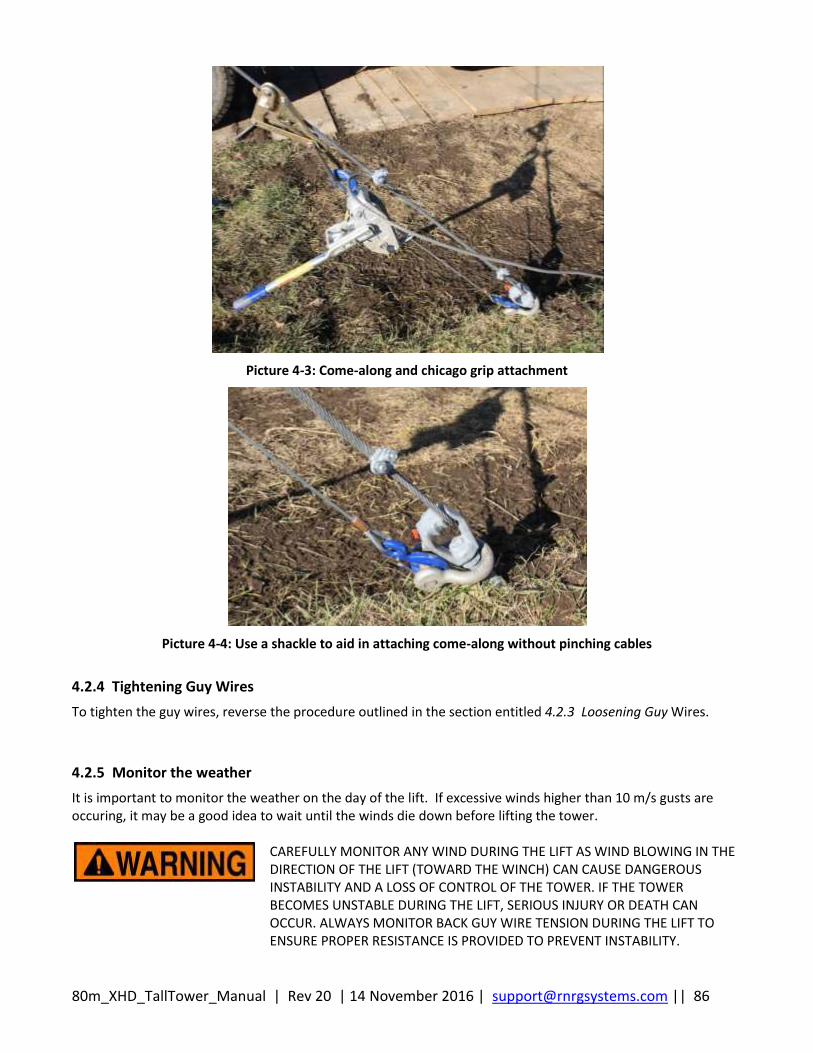
80m_XHD_TallTower_Manual | Rev 20 | 14 November 2016 | [email protected] || 86
Picture 4-3: Come-along and chicago grip attachment
Picture 4-4: Use a shackle to aid in attaching come-along without pinching cables
4.2.4 Tightening Guy Wires
To tighten the guy wires, reverse the procedure outlined in the section entitled 4.2.3 Loosening Guy Wires.
4.2.5 Monitor the weather
It is important to monitor the weather on the day of the lift. If excessive winds higher than 10 m/s gusts are occuring, it may be a good idea to wait until the winds die down before lifting the tower.
CAREFULLY MONITOR ANY WIND DURING THE LIFT AS WIND BLOWING IN THE DIRECTION OF THE LIFT (TOWARD THE WINCH) CAN CAUSE DANGEROUS INSTABILITY AND A LOSS OF CONTROL OF THE TOWER. IF THE TOWER BECOMES UNSTABLE DURING THE LIFT, SERIOUS INJURY OR DEATH CAN OCCUR. ALWAYS MONITOR BACK GUY WIRE TENSION DURING THE LIFT TO ENSURE PROPER RESISTANCE IS PROVIDED TO PREVENT INSTABILITY.
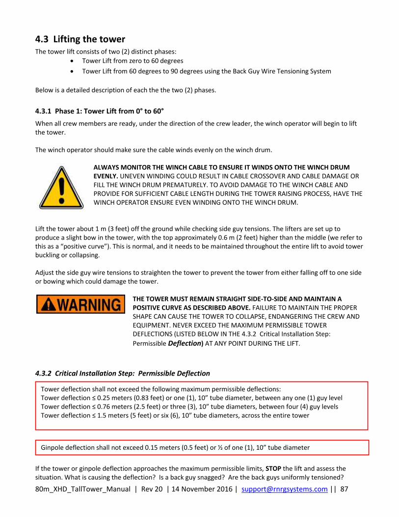
80m_XHD_TallTower_Manual | Rev 20 | 14 November 2016 | [email protected] || 87
4.3 Lifting the tower The tower lift consists of two (2) distinct phases:
Tower Lift from zero to 60 degrees
Tower Lift from 60 degrees to 90 degrees using the Back Guy Wire Tensioning System
Below is a detailed description of each the the two (2) phases.
4.3.1 Phase 1: Tower Lift from 0° to 60°
When all crew members are ready, under the direction of the crew leader, the winch operator will begin to lift the tower. The winch operator should make sure the cable winds evenly on the winch drum.
ALWAYS MONITOR THE WINCH CABLE TO ENSURE IT WINDS ONTO THE WINCH DRUM EVENLY. UNEVEN WINDING COULD RESULT IN CABLE CROSSOVER AND CABLE DAMAGE OR FILL THE WINCH DRUM PREMATURELY. TO AVOID DAMAGE TO THE WINCH CABLE AND PROVIDE FOR SUFFICIENT CABLE LENGTH DURING THE TOWER RAISING PROCESS, HAVE THE WINCH OPERATOR ENSURE EVEN WINDING ONTO THE WINCH DRUM.
Lift the tower about 1 m (3 feet) off the ground while checking side guy tensions. The lifters are set up to produce a slight bow in the tower, with the top approximately 0.6 m (2 feet) higher than the middle (we refer to this as a “positive curve”). This is normal, and it needs to be maintained throughout the entire lift to avoid tower buckling or collapsing. Adjust the side guy wire tensions to straighten the tower to prevent the tower from either falling off to one side or bowing which could damage the tower.
THE TOWER MUST REMAIN STRAIGHT SIDE-TO-SIDE AND MAINTAIN A POSITIVE CURVE AS DESCRIBED ABOVE. FAILURE TO MAINTAIN THE PROPER SHAPE CAN CAUSE THE TOWER TO COLLAPSE, ENDANGERING THE CREW AND EQUIPMENT. NEVER EXCEED THE MAXIMUM PERMISSIBLE TOWER DEFLECTIONS (LISTED BELOW IN THE 4.3.2 Critical Installation Step:
Permissible Deflection) AT ANY POINT DURING THE LIFT.
4.3.2 Critical Installation Step: Permissible Deflection
If the tower or ginpole deflection approaches the maximum permissible limits, STOP the lift and assess the situation. What is causing the deflection? Is a back guy snagged? Are the back guys uniformly tensioned?
Ginpole deflection shall not exceed 0.15 meters (0.5 feet) or ½ of one (1), 10” tube diameter
Tower deflection shall not exceed the following maximum permissible deflections: Tower deflection ≤ 0.25 meters (0.83 feet) or one (1), 10” tube diameter, between any one (1) guy level Tower deflection ≤ 0.76 meters (2.5 feet) or three (3), 10” tube diameters, between four (4) guy levels Tower deflection ≤ 1.5 meters (5 feet) or six (6), 10” tube diameters, across the entire tower
80m_XHD_TallTower_Manual | Rev 20 | 14 November 2016 | [email protected] || 88
Understand the cause of the deflection and correct the problem. Verify tower and ginpole deflections are well within the maximum permissible limits prior to proceeding with the tower lift. If the lateral tower deflection exceeds the limits, the side guys should be adjusted to straighten the tower. Watch the winch anchors for movement. The maximum lifting force will be experienced when the tower is first lifted a few feet off the ground. If the winch anchors do not hold, immediately lower the tower. If the winch anchors do not hold under the tower lift, either the anchors were installed incorrectly or another type of anchor is needed. See Appendix B: Anchoring Guidelines for more information. Watch the tower baseplate for movement toward the winch. If the baseplate slips during the first part of the tower lift, immediately lower the tower. Check that the anchor and bridle assembly are attached correctly to the pivot pipe of the basetube, there should not be movement of the baseplate during the tower erection. If everything looks acceptable, continue to lift the tower a little at a time, checking tower side guy tension throughout the lift. At times, it may be necessary to adjust the side guy wire tension, particularly if the side guys are above, below, or otherwise out of line with the tower pivot. In addition, regularly check the ginpole side guys to make sure their tensions are roughly equal and not too tight - verify there is a slight catenary in them at all times during the lift. If necessary, adjust the ginpole side guy wire tension by adding or removing slack. Do these checks and adjustments ONLY when the winch is stopped. See the sections entitled 4.5.1 Guy Tension Check and Adjusting Guy Wires for instructions on measuring and adjusting guy tension. Throughout the lift, the ginpole must remain in a straight line as viewed from the winch. If it leans to either side, the cause should be determined and corrected. The safety wire cable tension should be adjusted as needed to keep the ginpole centered. When adjusting the safety wire cable tension, lengthen the loose wire rope and shorten the tight wire rope (sounds backward, but it is correct). Do not allow the ginpole to be at a severe angle to the base plate pivot since the pivot loads will be all on one side of the gin pole. In this case, lower the tower, and then realign the tower with respect to the winch and/or level the baseplate as needed. Extreme imbalance in the ginpole side guys may overload the ginpole, resulting in ginpole collapse. Work slowly and smoothly. Fast, uneven movements tend to make the tower bounce, shake or swing. Be sure that communication between all members of the lifting team is clear and concise. Continue lifting and adjusting until the tower is about 60 degrees above horizontal (just above the half-way point). STOP.
4.3.3 Phase 2: Tower Lift from 60° to 90° using the Back Stay Tensioning System
Beyond 60 degrees above horizontal, it is absolutely essential that proper tension be maintained on all back guy wires during the last part of the lift. Utilizing the Back Stay Tensioning System is required to maintain measured tension on all 8 back guy wires. The tower will lift very easily at this point because the weight of the ginpole will be enough to tip the tower with little effort from the winch. Any wind blowing in the direction of the lift will also reduce the load on the winch; excessive wind in the direction of the lift can lead to a loss of control of the tower. Therefore, the crew must control the lift from this point by utilizing the Back Stay Tensioning System (see Appendix E for full procedure). Phase 2 of lifting from 60° to 80° uses the Back Stay Tensioning System with a maximum tension on the scales of 200 lbf. Lifting from 80° to 90° uses the Back Stay Tensioning System with a maximum tension on the scales of 150 lbf. Reference Appendix E for full procedure.

80m_XHD_TallTower_Manual | Rev 20 | 14 November 2016 | [email protected] || 89
Follow the procedure in Appendix E for the remainder of the lift. This will bring you to the point of transfering your front guy wires and straightening your tower.
4.4 Attaching Front Guy Wires When the top of the tower is over the baseplate and nearly vertical, it is time to transfer the Front Guy Wires to the front anchors. Prior to attaching the front guy wires to the front anchors, set all load scales to 100 lbf. If all procedures have been followed correctly, the front guy wires are attached to the lifters at the top of the ginpole. One-by-one, start with front guy #8 (top level) and work down the tower. Detach the front guy wire and make sure it is on the opposite side of the ginpole in relation to where the lifter anchor is located. If this is not done correctly for each front guy wire, they will tangle with the lifters when the lifters are transferred to their anchor. Once you have the front guy wire on the correct side of the ginpole, walk it out and attach to the correct front anchor. Hand tighten using multiple people. Repeat this process until all 8 front guy wires are attached to the front anchors.
4.5 Plumb and Straighten Tower
Picture 4-5: Straightening your tower
Utilizing the back guywire tensioning system, plumbing the tower has become more efficient. The back guywire tensioner provides constant tension to the back guywires during the tower plumbing and straightening process. Prior to transferring the front guy wires, all load scales were set to 100 lbf ± 10 lbf. Personnel stationed at the back stay tensioners shall monitor and maintain tension on all load scales during the plumbing and straightening process.
80m_XHD_TallTower_Manual | Rev 20 | 14 November 2016 | [email protected] || 90
Using a carpenter or digital level, measure the verticality of the base tube. Adjust the lower level guy wires as needed until the base tube is vertical (90° ± 0.5°). It may take multiple adjustments from the bottom to the top of the tower before the tower is completely plumb. Starting with level 1 and working your way up the tower, have 2-3 technicians working at the front anchors utilizing Chicago grips and come-alongs to tension the guy wires. First, set level #1 back guy tension to 60 lbf using the worm gear, then pull in on the #1 front guy wire to straighten the tower. As level #1 front guy wire is being tensioned, the scale measuring the back guy wire for level #1 will increase. Slowly feather the worm gear tension on the back guy wire to remain at 60 lbf while the front guy wire is tensioned. Once you achieve the desired tower location for level one. Lock down the front guy wire at the anchor point with the correct wire rope clips and re-tension the scale on the back guy wire to 100lbf. You will notice that the levels above and sometimes below the one you are working on will increase their tension as you plumb the tower. Keep tensions at 150 lbf or below if they try to spike to higher tensions. Move to level 2 and repeat the same process. It may be necessary to skip guy levels and work on a particular level that is too far out of alignment. You should always try to keep the tower as straight as possible while plumbing the tower. When the tower is plumb, set up on the back anchors with a come-along and Chicago grip. One level at a time starting with level 1, pull in the slack on the back guy wire while letting out on the worm gear until the easy feed pulley is no longer holding the back guy wire. Remove pulley and fasten guy wire to anchor at the correct pulse method tension. When the tower is plumb, all guywires shall be properly tensioned mechanically and tested using the pulse method for guy tension. See table 4-1 below for proper pulse method guy tensions. Once the tower is plumb (within one-quarter (¼), 10” tube diameter over entire tower), make final adjustments to the guy wires so that they are properly tensioned (see section entitled 4.5.1 Guy Tension Check for details).
4.5.1 Guy Tension Check
We recommend two (2) techniques outlined in ANSI/TIA-222-G to more accurately set guy wire tensions to ensure they are consistent and match well with the tensions assumed during the tower structural analysis. The two (2) methods described below are:
Pulse Method
Tangent Intercept Method
PROPER GUY WIRE TENSION IS CRITICAL. FAILURE TO ENSURE PROPER GUY WIRE TENSION CAN CAUSE A FAILURE OF THE TOWER, GUY WIRES OR GUY ANCHORS RESULTING IN SERIOUS INJURY, DEATH OR PROPERTY DAMAGE. ONCE LIFTED, ALWAYS READ AND FOLLOW INSTRUCTIONS FOR MEASURING AND REACHING PROPER GUY WIRE TENSION.
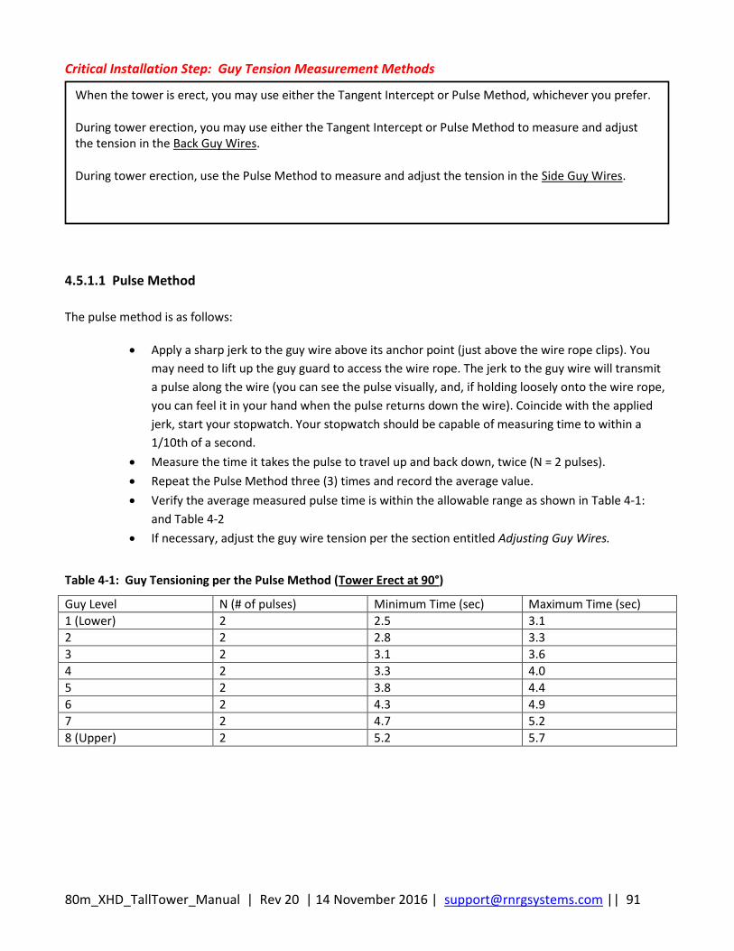
80m_XHD_TallTower_Manual | Rev 20 | 14 November 2016 | [email protected] || 91
Critical Installation Step: Guy Tension Measurement Methods
4.5.1.1 Pulse Method
The pulse method is as follows:
Apply a sharp jerk to the guy wire above its anchor point (just above the wire rope clips). You
may need to lift up the guy guard to access the wire rope. The jerk to the guy wire will transmit
a pulse along the wire (you can see the pulse visually, and, if holding loosely onto the wire rope,
you can feel it in your hand when the pulse returns down the wire). Coincide with the applied
jerk, start your stopwatch. Your stopwatch should be capable of measuring time to within a
1/10th of a second.
Measure the time it takes the pulse to travel up and back down, twice (N = 2 pulses).
Repeat the Pulse Method three (3) times and record the average value.
Verify the average measured pulse time is within the allowable range as shown in Table 4-1:
and Table 4-2
If necessary, adjust the guy wire tension per the section entitled Adjusting Guy Wires.
Table 4-1: Guy Tensioning per the Pulse Method (Tower Erect at 90°)
Guy Level N (# of pulses) Minimum Time (sec) Maximum Time (sec)
1 (Lower) 2 2.5 3.1
2 2 2.8 3.3
3 2 3.1 3.6
4 2 3.3 4.0
5 2 3.8 4.4
6 2 4.3 4.9
7 2 4.7 5.2
8 (Upper) 2 5.2 5.7
When the tower is erect, you may use either the Tangent Intercept or Pulse Method, whichever you prefer. During tower erection, you may use either the Tangent Intercept or Pulse Method to measure and adjust the tension in the Back Guy Wires. During tower erection, use the Pulse Method to measure and adjust the tension in the Side Guy Wires.

80m_XHD_TallTower_Manual | Rev 20 | 14 November 2016 | [email protected] || 92
Table 4-2: Guy Tensioning per the Pulse Method (During Tower Erection)
Guy Level N (# of pulses) Minimum Time (sec) Maximum Time (sec)
1 (Lower) 2 2.5 4.3
2 2 2.8 4.4
3 2 3.1 5.1
4 2 3.3 5.8
5 2 3.8 6.4
6 2 4.3 7.1
7 2 4.7 7.6
8 (Upper) 2 5.2 7.6
For ease of measuring and efficiency of checking the tension of all (8) eight levels of guy wires during the lifting process. Measuring with the Pulse method using 1 pulse (N=1) is acceptable. The chart below shows in green the optimal tension that you want to achieve for each level during the tower erection. The seconds counted for a single pulse (up to the guy ring and back to your hand) should equal the seconds shown on the top line of the chart for each level.
Table 4-3: Guy Tension for pulse method (during tower erection) N = 1.
Use Table 4-3 shown above for testing side guy wire tension during the tower lift. N=1 is the time that it takes for the pulse of the cable when hit with your hand to travel up to the guy ring at the tower and back to your hand. The time in seconds and tension highlighted in green is where each level should be during the entire tower erection. While the tower is being raised it is more efficient to use the N=1 method to confirm guy wire tension.
Once the tower is vertical, all guy wires must to be tensioned using the N=2 method shown above in Table 4-1.
Guy LevelN (# of
pulses) 6 5 4 3 2 1
8 (top) 1 81 117 183 325 732 2929
7 1 69 99 154 274 617 2468
6 1 38 54 84 150 338 1352
5 1 31 44 69 123 276 1103
4 1 25 37 57 102 229 916
3 1 18 26 41 73 165 659
2 1 15 22 35 62 139 554
1 (Bottom) 1 14 20 31 55 123 491
During Tower Erection
Tension (lbf) for Pulse Times (sec)
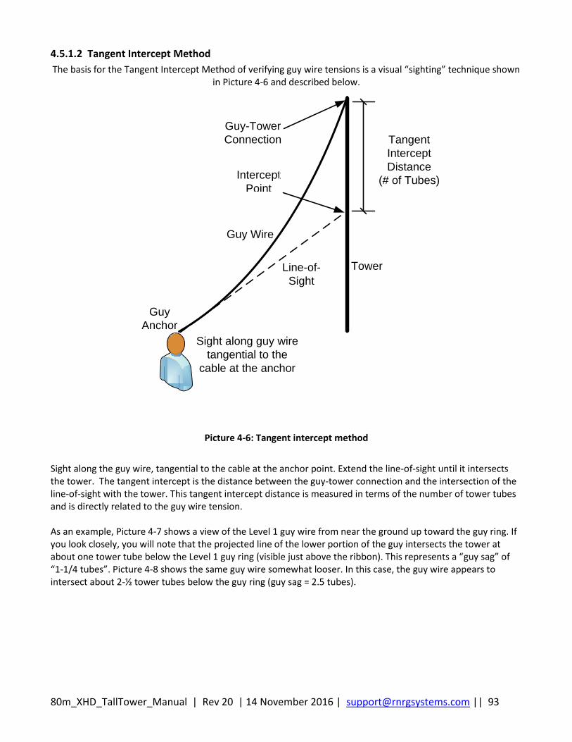
80m_XHD_TallTower_Manual | Rev 20 | 14 November 2016 | [email protected] || 93
4.5.1.2 Tangent Intercept Method
The basis for the Tangent Intercept Method of verifying guy wire tensions is a visual “sighting” technique shown in Picture 4-6 and described below.
Intercept
Point
Guy-Tower
Connection
Guy
Anchor
Tangent
Intercept
Distance
(# of Tubes)
Tower
Guy Wire
Line-of-
Sight
Sight along guy wire
tangential to the
cable at the anchor
Picture 4-6: Tangent intercept method
Sight along the guy wire, tangential to the cable at the anchor point. Extend the line-of-sight until it intersects the tower. The tangent intercept is the distance between the guy-tower connection and the intersection of the line-of-sight with the tower. This tangent intercept distance is measured in terms of the number of tower tubes and is directly related to the guy wire tension. As an example, Picture 4-7 shows a view of the Level 1 guy wire from near the ground up toward the guy ring. If you look closely, you will note that the projected line of the lower portion of the guy intersects the tower at about one tower tube below the Level 1 guy ring (visible just above the ribbon). This represents a “guy sag” of “1-1/4 tubes”. Picture 4-8 shows the same guy wire somewhat looser. In this case, the guy wire appears to intersect about 2-½ tower tubes below the guy ring (guy sag = 2.5 tubes).
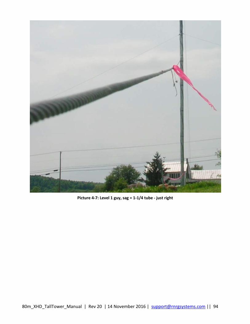
80m_XHD_TallTower_Manual | Rev 20 | 14 November 2016 | [email protected] || 94
Picture 4-7: Level 1 guy, sag = 1-1/4 tube - just right

80m_XHD_TallTower_Manual | Rev 20 | 14 November 2016 | [email protected] || 95
Picture 4-8: Level 1, guy sag = 2.5 tubes - too loose
Using this sighting technique, adjust guy tensions to fit within the limits shown in Table 4-4 or Table 4-5 below.
Table 4-4: Guy Tensioning per the Tangent Intercept Method (Tower Erect at 90°)
Guy Level Guy Slack Range (# of Tubes below Guy Ring)
Least Sag Most Sag
1 (Lower) 1 1 1/2
2 1 ¼ 1 ¾
3 1 ½ 2
4 1 ¾ 2 1/2
5 2 ¼ 3
6 (Including transition as one tube)
3 ¼ 4
7 3 ¼ 4
8 (Upper) 4 4 ¾
As an example, for Level 1, the least sag the guy wire should have is 1 tube; the most sag is 1 ½ tubes. Therefore, the guy wire in Picture 4-7 (sag = 1-1/4 tubes) meets the requirement, but the guy wire in Picture 4-8 above (guy sag = 2.5 tubes) is too loose.

80m_XHD_TallTower_Manual | Rev 20 | 14 November 2016 | [email protected] || 96
Table 4-5: Guy Tensioning per the Tangent Intercept Method (During Tower Erection)
Guy Level Guy Slack Range (# of Tubes below Guy Ring)
Least Sag Most Sag
1 (Lower) 1 3
2 1 ¼ 3
3 1 ½ 4
4 1 ¾ 5
5 2 ¼ 6
6 (Including transition as one tube)
3 ¼ 7
7 3 ¼ 8
8 (Upper) 4 8
4.6 Transfer Lifters Transfer the lifting guy wires one at a time from the ginpole to the spare 8 inch diameter screw-in anchor located approximately 5 meters (15 feet) from the tower baseplate, in close proximity to the ginpole. Prepare the 8 inch screw-in anchor by attaching two large medium duty thimbles, as shown in Picture 4-9. The thimbles are attached to the 8 inch anchor using a short-run of 5/6 inch diameter wire rope and three (3) 5/16” wire rope clips.
Picture 4-9: Lifter storage
Medium duty thimble
8 inch anchor
Lifters
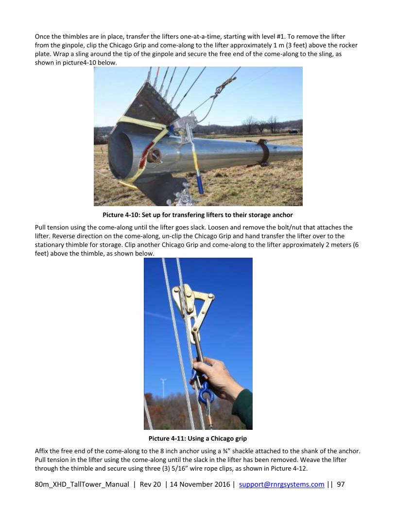
80m_XHD_TallTower_Manual | Rev 20 | 14 November 2016 | [email protected] || 97
Once the thimbles are in place, transfer the lifters one-at-a-time, starting with level #1. To remove the lifter from the ginpole, clip the Chicago Grip and come-along to the lifter approximately 1 m (3 feet) above the rocker plate. Wrap a sling around the tip of the ginpole and secure the free end of the come-along to the sling, as shown in picture4-10 below.
Picture 4-10: Set up for transfering lifters to their storage anchor
Pull tension using the come-along until the lifter goes slack. Loosen and remove the bolt/nut that attaches the lifter. Reverse direction on the come-along, un-clip the Chicago Grip and hand transfer the lifter over to the stationary thimble for storage. Clip another Chicago Grip and come-along to the lifter approximately 2 meters (6 feet) above the thimble, as shown below.
Picture 4-11: Using a Chicago grip
Affix the free end of the come-along to the 8 inch anchor using a ¾” shackle attached to the shank of the anchor. Pull tension in the lifter using the come-along until the slack in the lifter has been removed. Weave the lifter through the thimble and secure using three (3) 5/16” wire rope clips, as shown in Picture 4-12.
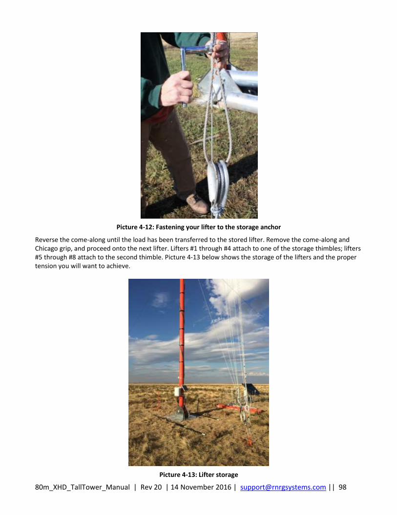
80m_XHD_TallTower_Manual | Rev 20 | 14 November 2016 | [email protected] || 98
Picture 4-12: Fastening your lifter to the storage anchor
Reverse the come-along until the load has been transferred to the stored lifter. Remove the come-along and Chicago grip, and proceed onto the next lifter. Lifters #1 through #4 attach to one of the storage thimbles; lifters #5 through #8 attach to the second thimble. Picture 4-13 below shows the storage of the lifters and the proper tension you will want to achieve.
Picture 4-13: Lifter storage

80m_XHD_TallTower_Manual | Rev 20 | 14 November 2016 | [email protected] || 99
On the last lifter, #8 (top) lifter, you will be releasing the thimble from the rocker plate at the end of the ginpole, then utilizing the come-along to lower the ginpole all the way to the ground. It is helpful to block under the jumper struts in order to support the ginpole when it reaches the ground.
4.7 Final Inspection and Maintenance Tighten all wire rope clips on each guy wire, allowing approximately 100 mm to 200 mm (4 inches to 8 inches) between clips. Final torque on wire rope clips should be as listed in Table 4-6: below.
Table 4-6: Wire Rope Clip Torque Values
Wire rope clip size (inches) Torque Wrench N-m (ft-lbf)
3/16 10 (7.5)
5/16 41 (30)
3/8 61 (45)
The ginpole may be left in place, or it may be removed and disassembled, if desired. If using guy guards, attach one to each guy wire as well as the ginpole lateral guy wires. Guy guards may be necessary in areas:
Where snow is prevalent
Grazing animals are present
Field mowing will be necessary
Check the tower in 2 or 3 weeks; tighten loose guys and straighten the tower if needed. It is especially important to do this before any icing events occur. Also check the guy wires after any severe ice or wind storm. Some settling of the tower or anchors may occur, and guy wires can stretch. Loose guy wires can also result when the wire rope clips securing the guys are forced down by the impact of sliding ice.
Picture 4-14: Guy guards
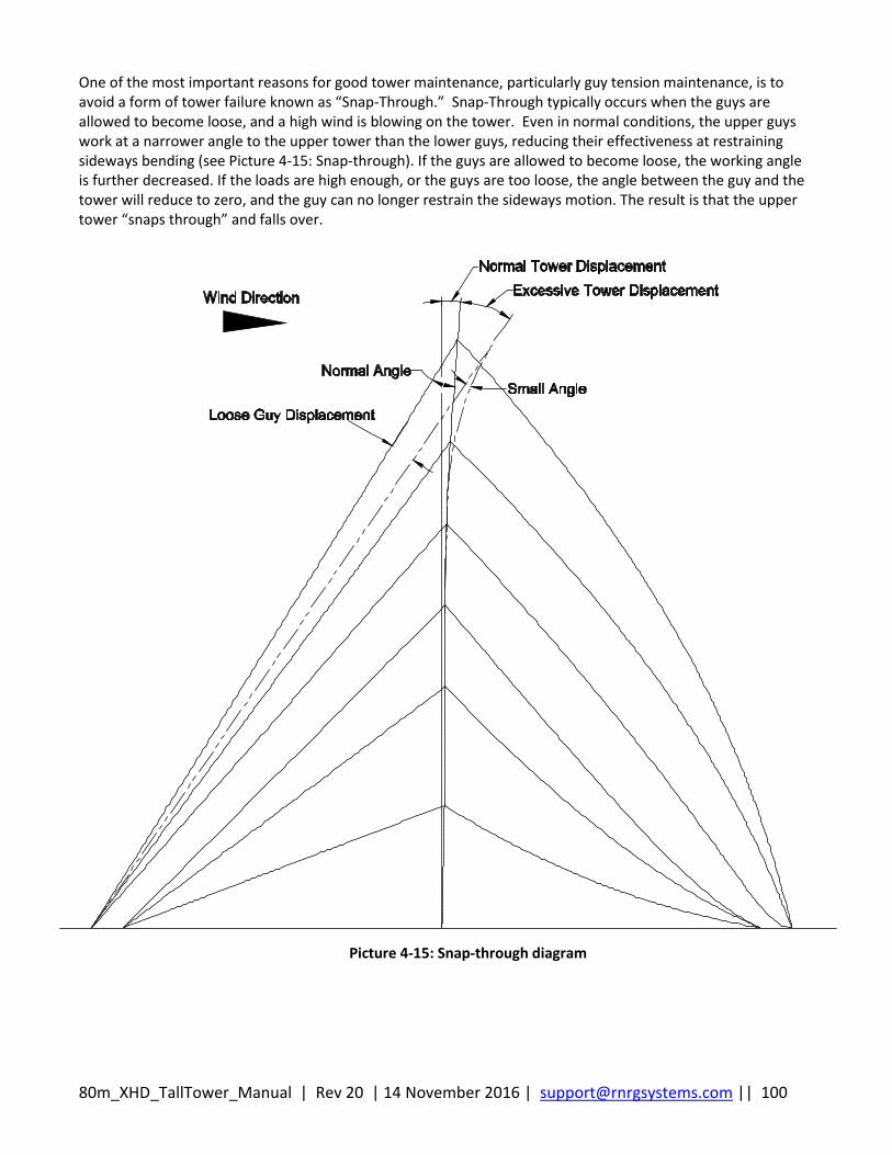
80m_XHD_TallTower_Manual | Rev 20 | 14 November 2016 | [email protected] || 100
One of the most important reasons for good tower maintenance, particularly guy tension maintenance, is to avoid a form of tower failure known as “Snap-Through.” Snap-Through typically occurs when the guys are allowed to become loose, and a high wind is blowing on the tower. Even in normal conditions, the upper guys work at a narrower angle to the upper tower than the lower guys, reducing their effectiveness at restraining sideways bending (see Picture 4-15: Snap-through). If the guys are allowed to become loose, the working angle is further decreased. If the loads are high enough, or the guys are too loose, the angle between the guy and the tower will reduce to zero, and the guy can no longer restrain the sideways motion. The result is that the upper tower “snaps through” and falls over.
Picture 4-15: Snap-through diagram

80m_XHD_TallTower_Manual | Rev 20 | 14 November 2016 | [email protected] || 101
MAINTAINING PROPER GUY WIRE TENSION IS CRITICAL. FAILURE TO MAINTAIN PROPER GUY WIRE TENSION AFTER INSTALLATION CAN CAUSE A FAILURE OF THE TOWER, GUY WIRES OR GUY ANCHORS RESULTING IN SERIOUS INJURY, DEATH OR PROPERTY DAMAGE. AFTER INSTALLATION, IT IS IMPORTANT TO CHECK GUY WIRE TENSION PERIODICALLY AND ENSURE PROPER TENSION MEASUREMENTS ARE MAINTAINED. ALWAYS READ AND FOLLOW INSTRUCTIONS FOR MAINTAINING PROPER GUY WIRE TENSION.
80m_XHD_TallTower_Manual | Rev 20 | 14 November 2016 | [email protected] || 102
Chapter 5: Tower Lowering
5.1 Tower Lowering Overview Lowering the tower is the reverse of raising the tower, though there are differences between the methods and a few additional precautions. As with lifting, tower lowering consists of three (3) distinct phases:
Tower Lowering from 90° to 80 (Max tension on back stay tensioning system = 150 lbf.)
Tower Lowering from 80° to 60° (Max tension on back stay tensioning system = 200 lbf.)
Tower Lowering from 60° to 0°
Each of the phases of tower lowering is described below.
5.1.1 Critical Installation Step: Tensioning the ginpole jumper strut cables
MAINTAINING PROPER GINPOLE JUMPER STRUT CABLE TENSION DURING LOWERING IS CRITICAL. FAILURE TO MAINTAIN PROPER GINPOLE JUMPER STRUT CABLE TENSION DURING LOWERING CASE CAUSE THE GINPOLE TO BEND OR COLLAPSE RESULTING IN SERIOUS INJURY, DEATH OR PROPERTY DAMAGE. IT IS THEREFORE IMPORTANT TO CHECK AND MAINTAIN TENSION ON THE GINPOLE JUMPER STRUT CABLE. ALWAYS READ AND FOLLOW INSTRUCTIONS FOR MAINTAINING PROPER TENSION.
5.1.2 Critical Installation Procedure: Utilize the Back Stay Tensioning System
5.1.3 Phase 1: Tower Lowering from 90° to 60° (Max tension on back stay tensioning system = 150
lbf.)
For the tower lowering between 90° and 80°, it is imperative the Back Stay Tensioning System is used to incrementally lower the tower. The Back Stay Tensioning System ensures tension exists on the back guy wires at all times during the lowering when the tower is between 90° and 80°. Failure to provide sufficient tension on the back guy wires (e.g., not using the Back Stay Tensioning System) may result in the tower deforming or buckling. All terrain slopes from flat to 3% require the use of the Back Stay Tensioning System.
If the ginpole was removed, set-up the ginpole as described in the section entitled Ginpole. Make sure the ginpole jumper strut cables are properly tensioned.
80m_XHD_TallTower_Manual | Rev 20 | 14 November 2016 | [email protected] || 103
ALWAYS MAINTAIN PROPER TENSION ON GUY WIRES DURING THE LOWERING PROCESS, ESPECIALLY WHEN THE TOWER IS BETWEEN 90° AND 60°. FAILURE TO MAINTAIN PROPER GUY WIRE TENSION CAN CAUSE DEFORMATION OR OTHER DAMAGE TO THE TOWER. ALWAYS READ AND FOLLOW LOWERING INSTRUCTIONS FOR INCREMENTAL LOWERING AND CAREFULLY UTILIZE THE BACK STAY TENSIONING SYSTEM METHOD SET FORTH IN THE INSTALLATION MANUAL.
If the tower will be lowered onto blocking, place the blocking now while it is still safe to work under the tower. Remove the upper level lifter from the storage thimble and walk it over to the ginpole. Attach a sling to the end of the ginpole. To the lifter, attach a Chicago Grip and come-along approximately 1 m (3 feet) from the thimble. Attach the free end of the come-along to the sling and lift the ginpole. Affix the lifter to the rocker plate on the ginpole. Repeat the transfer process for the remaining lifters. Disconnect the front guys, starting with Level 1 and working up to Level 8. With the tower vertical at 90°, apply 150 lbf to all 8 of the back guy wires utilizing the back stay tensioning system. See Appendix E for full procedure. In incremental lowering steps, lower to the point where the one of the levels reaches the minimum tension stated for each level in the back stay tensioning system. Stop the lift and tension all 8 levels back to 150 lbf. Continue this method until you reach 80 degrees.
5.1.3 Tower Lowering from 80° to 60°
Continue the incremental lowering technique similar to phase 1. The maximum tension that can be placed on all 8 levels of back guy wires is 200 lbf. Start your lowering with scales at 200 lbf, then lower until one of the levels reaches the minumum tension level. Stop the lift and re-tension all 8 levels to 200 lbf. As the tower is lowered and reaches an angle of 60°, it is no longer necessary to maintain manual tension on the back guy wires. The Back Stay Tensioning system can be left where it is until the tower in on the ground.
5.1.4 Phase 2: Tower Lowering from 60° to 0°
Continue lowering the tower by letting out the winch cable. Stop the winch at least every 20 degrees to re-check side-guy wire tension. Refer to the sections entitled Guy Tension Check and Adjusting Guy Wires for instructions on measuring and adjusting guy tension. It is critical to keep the tower straight at all times. This is particularly important when the tower is near the ground where forces are at their greatest and most difficult to control. The force on the winch is greatest as the tower nears the ground. Be sure to stand to either side of the winch cable, rather than directly in line with it. To lower the ginpole, put the helper ginpole in place before the ginpole reaches 45°. As the ginpole nears the ground, place the winch cable (all five (5) strands) into the 5 V-belt pulleys on the top of the helper ginpole. You will need the use of a 3 meter (10 foot) ladder to access the V-belt pulleys. The pole can then be lowered to the ground.
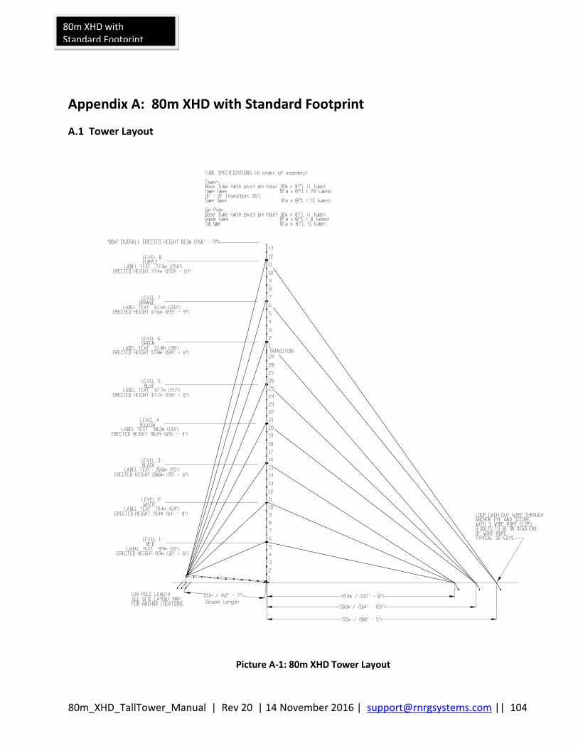
80m_XHD_TallTower_Manual | Rev 20 | 14 November 2016 | [email protected] || 104
80m XHD with Standard Footprint
Appendix A: 80m XHD with Standard Footprint
A.1 Tower Layout
Picture A-1: 80m XHD Tower Layout
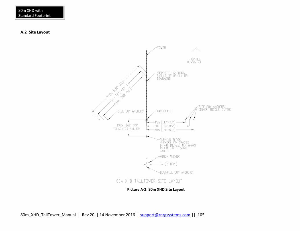
80m_XHD_TallTower_Manual | Rev 20 | 14 November 2016 | [email protected] || 105
80m XHD with Standard Footprint
A.2 Site Layout
Picture A-2: 80m XHD Site Layout
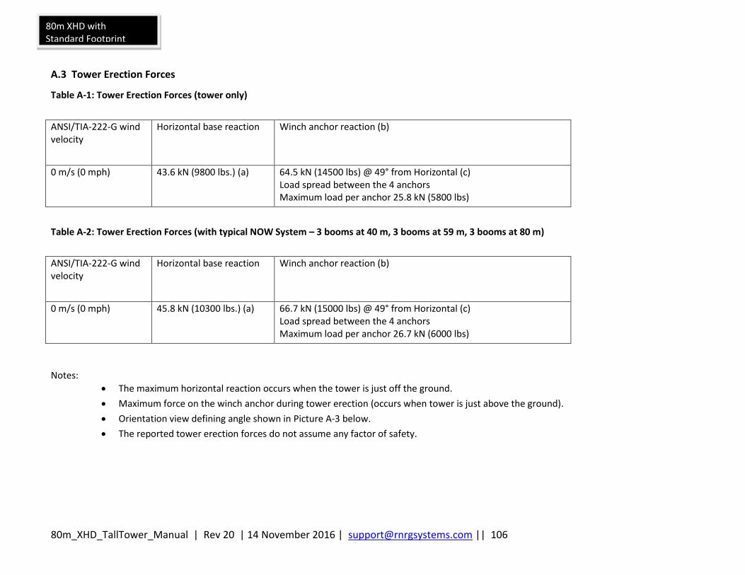
80m_XHD_TallTower_Manual | Rev 20 | 14 November 2016 | [email protected] || 106
80m XHD with Standard Footprint
A.3 Tower Erection Forces
Table A-1: Tower Erection Forces (tower only)
ANSI/TIA-222-G wind velocity
Horizontal base reaction Winch anchor reaction (b)
0 m/s (0 mph) 43.6 kN (9800 lbs.) (a) 64.5 kN (14500 lbs) @ 49° from Horizontal (c) Load spread between the 4 anchors Maximum load per anchor 25.8 kN (5800 lbs)
Table A-2: Tower Erection Forces (with typical NOW System – 3 booms at 40 m, 3 booms at 59 m, 3 booms at 80 m)
ANSI/TIA-222-G wind velocity
Horizontal base reaction Winch anchor reaction (b)
0 m/s (0 mph) 45.8 kN (10300 lbs.) (a) 66.7 kN (15000 lbs) @ 49° from Horizontal (c) Load spread between the 4 anchors Maximum load per anchor 26.7 kN (6000 lbs)
Notes:
The maximum horizontal reaction occurs when the tower is just off the ground.
Maximum force on the winch anchor during tower erection (occurs when tower is just above the ground).
Orientation view defining angle shown in Picture A-3 below.
The reported tower erection forces do not assume any factor of safety.
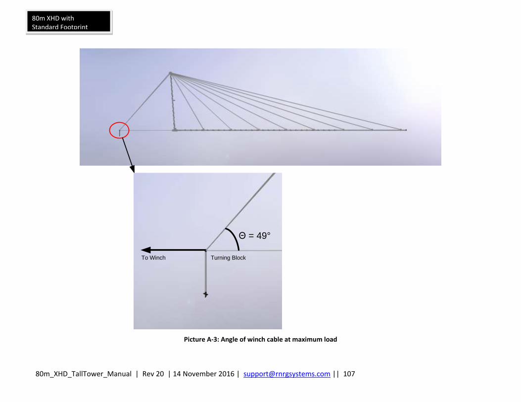
80m_XHD_TallTower_Manual | Rev 20 | 14 November 2016 | [email protected] || 107
80m XHD with Standard Footprint
To Winch Turning Block
Θ = 49°
Picture A-3: Angle of winch cable at maximum load

80m_XHD_TallTower_Manual | Rev 20 | 14 November 2016 | [email protected] || 108
80m XHD with Standard Footprint
A.4 ANSI/TIA-222-G Compliance Limits, Maximum Anchor Loads, and Baseplate Loads
The following graphs allow you to verify your tower meets ANSI/TIA-222-G requirements. Reactions and member forces apply to an 80m XHD TallTower equipped with galvanized steel wire rope per Federal Specification RR-W-410F. For an 80m XHD TallTower equipped with stainless steel wire rope per Federal Specification RR-W-410F, the limit load for wind with 6.4 mm (0.25 in) ice is reduced to 45.2 m/s (101 mph) 3-second gust. To use the graphs, you will need to obtain wind and wind with ice load requirements. ANSI/TIA-222-G Annex B lists design criteria for U.S. counties and its territories. You should also confirm the design criteria with your local permitting agency. Using wind and wind with ice design values, find the point at which they intersect on graphs shown in Picture A-4 or Picture A-5 and verify that this point is within the recommended operating zone. Maximum anchor loads and baseplate loads are obtainable using Pictures A-8 through A-11 , below. Consideration for unusual winds and winds with ice must be given to mountainous terrain and gorges. Please note that these graphs are based on the 3-second gust definition of wind speed per ANSI/TIA-222-G.
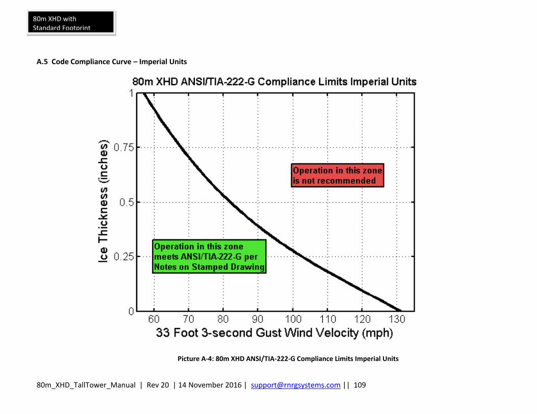
80m_XHD_TallTower_Manual | Rev 20 | 14 November 2016 | [email protected] || 109
80m XHD with Standard Footprint
A.5 Code Compliance Curve – Imperial Units
Picture A-4: 80m XHD ANSI/TIA-222-G Compliance Limits Imperial Units

80m_XHD_TallTower_Manual | Rev 20 | 14 November 2016 | [email protected] || 110
80m XHD with Standard Footprint
A.6 Code Compliance Curve – SI Units
Picture A-5: 80m XHD ANSI/TIA-222-G Compliance Limits SI Units
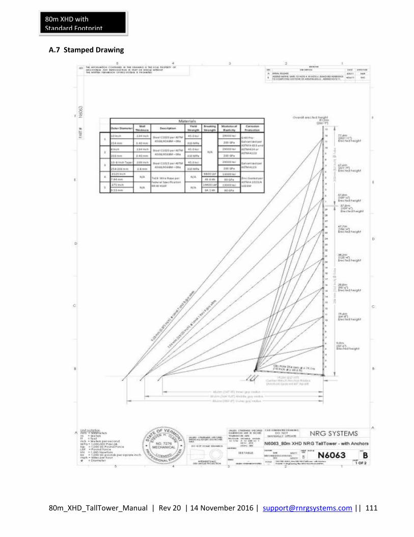
80m_XHD_TallTower_Manual | Rev 20 | 14 November 2016 | [email protected] || 111
80m XHD with Standard Footprint
A.7 Stamped Drawing
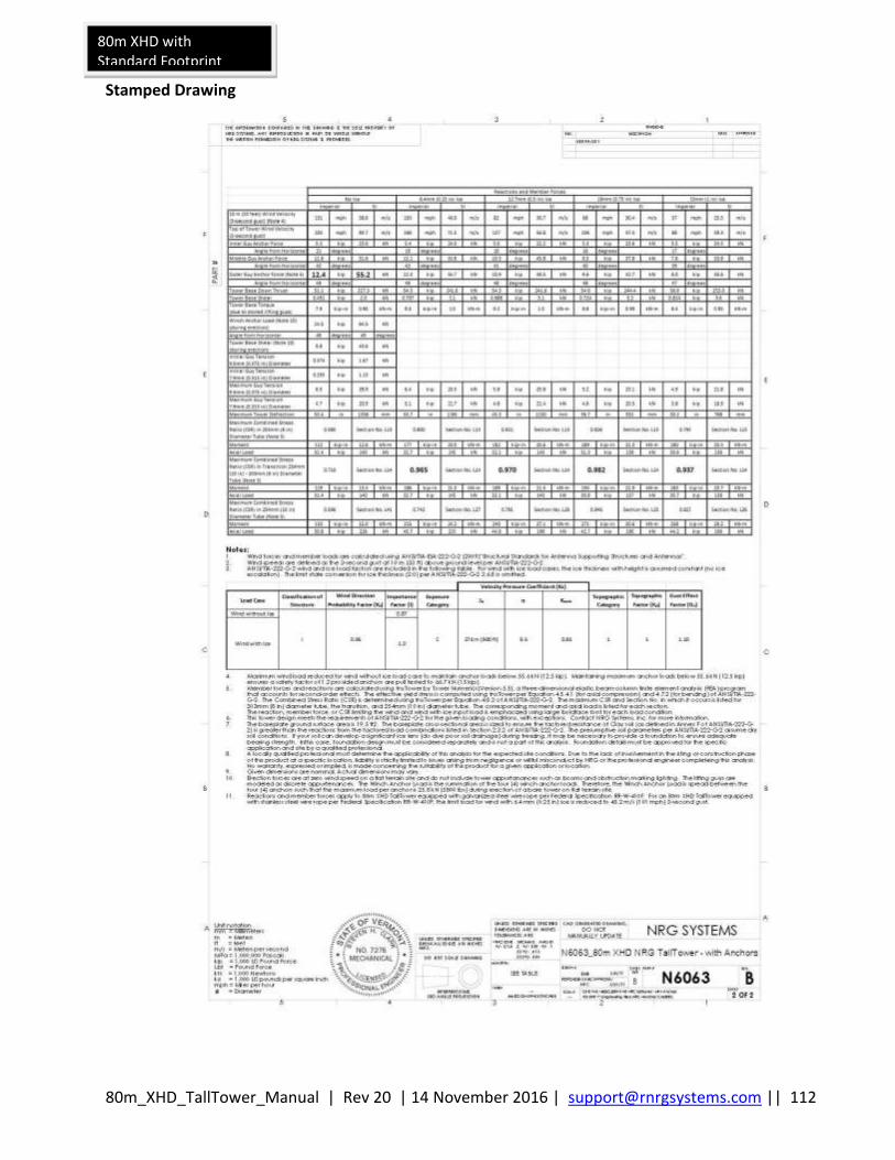
80m_XHD_TallTower_Manual | Rev 20 | 14 November 2016 | [email protected] || 112
80m XHD with Standard Footprint
Stamped Drawing
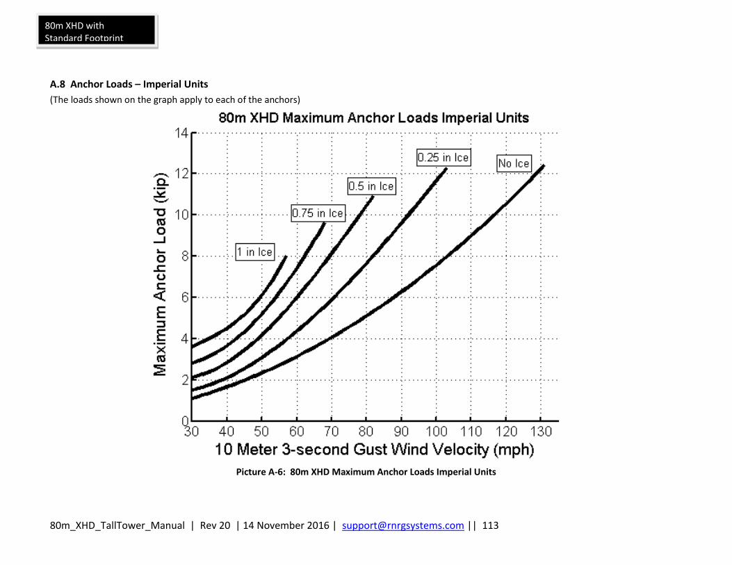
80m_XHD_TallTower_Manual | Rev 20 | 14 November 2016 | [email protected] || 113
80m XHD with Standard Footprint
A.8 Anchor Loads – Imperial Units
(The loads shown on the graph apply to each of the anchors)
Picture A-6: 80m XHD Maximum Anchor Loads Imperial Units
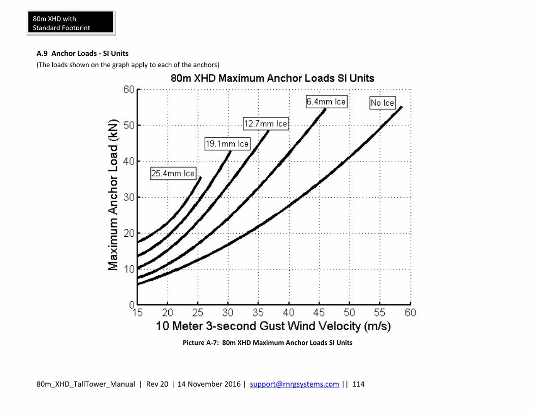
80m_XHD_TallTower_Manual | Rev 20 | 14 November 2016 | [email protected] || 114
80m XHD with Standard Footprint
A.9 Anchor Loads - SI Units
(The loads shown on the graph apply to each of the anchors)
Picture A-7: 80m XHD Maximum Anchor Loads SI Units
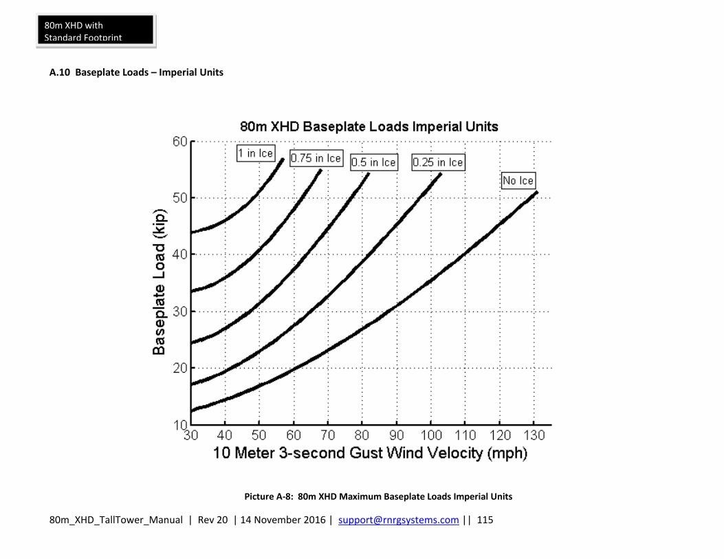
80m_XHD_TallTower_Manual | Rev 20 | 14 November 2016 | [email protected] || 115
80m XHD with Standard Footprint
A.10 Baseplate Loads – Imperial Units
Picture A-8: 80m XHD Maximum Baseplate Loads Imperial Units
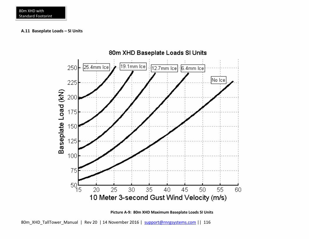
80m_XHD_TallTower_Manual | Rev 20 | 14 November 2016 | [email protected] || 116
80m XHD with Standard Footprint
A.11 Baseplate Loads – SI Units
Picture A-9: 80m XHD Maximum Baseplate Loads SI Units

80m_XHD_TallTower_Manual | Rev 20 | 14 November 2016 | [email protected] || 117
Appendix B: Anchoring Guidelines
B.1 Determine site soil and anchor type before you order your tower
Per ANSI/TIA-222-G, for design purposes, one can assume Class 6 soils. However, the Standard requires that soil parameters and assumptions be validated prior to installing the tower. Before your tower is ordered, determine the soil type, preferably through soil sampling. Order the correct anchors based on the results of the soil sample. The purpose of this section is to give you the information needed to provide suitable anchoring for your 80m TallTower. Because anchor requirements are site specific, it is the responsibility of the customer to determine suitable anchors. If you are not sure what is required, seek professional guidance. Local utility companies can often provide useful information regarding anchoring used in the site area. Do not use rebar anchors, especially when the surface soils are loose or wet.
Table B-1: Soil Classes
Class Common Soil Types Geological Soil Classification
3 Dense clays, sands and gravel; hard silts and clays
Glacial till; weathered shales, schist, gneiss and siltstone
4 Medium dense sandy gravel; very stiff to hard silts and clays
Glacial till; hardpan; marls
5 Medium dense coarse sand and sandy gravels; stiff to very stiff silts and clays
Saprolites, residual soils
6 Loose to medium dense fine to coarse sand; firm to stiff clays and silts
Dense hydraulic fill; compacted fill; residual soils
7** Loose fine sand; Alluvium; loess; soil-firm clays; varied clays; fill
Flood plain soils; lake clays; adobe; gumbo; fill
** In class 7 soils, it is advisable to place anchors deep enough to penetrate underlying class 5 or 6 soil.
Charts reproduced by permission, The A.B. Chance Company.
B.2 Anchor Choices and other considerations
The choice of anchors must take into consideration soil type, maximum winds expected, icing or other weather that may affect the tower, and a safety factor suitable for the location and to meet any legal requirements. Considerations include but are not limited to: tornadoes, hurricanes or typhoons, locations where very high winds are expected, potential for flooding or periodic soaking of the soil, soil erosion, and icing events.
B.3 Screw-In Anchor Description
Screw-in anchors are the most commonly used anchors for normal clay soils without rocks. The 8 inch single helix anchors are installed by hand, using a cross bar to screw them into the earth like a corkscrew. The 8 inch twin helix anchors require machinery.
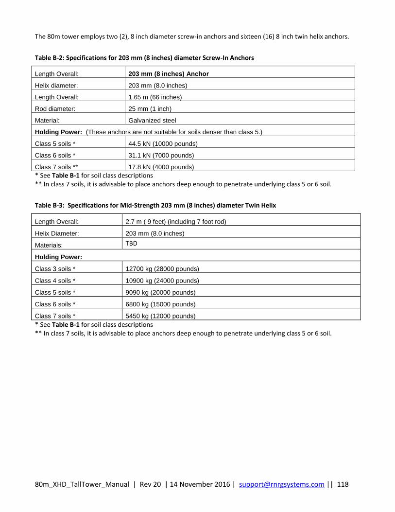
80m_XHD_TallTower_Manual | Rev 20 | 14 November 2016 | [email protected] || 118
The 80m tower employs two (2), 8 inch diameter screw-in anchors and sixteen (16) 8 inch twin helix anchors.
Table B-2: Specifications for 203 mm (8 inches) diameter Screw-In Anchors
Length Overall: 203 mm (8 inches) Anchor
Helix diameter: 203 mm (8.0 inches)
Length Overall: 1.65 m (66 inches)
Rod diameter: 25 mm (1 inch)
Material: Galvanized steel
Holding Power: (These anchors are not suitable for soils denser than class 5.)
Class 5 soils * 44.5 kN (10000 pounds)
Class 6 soils * 31.1 kN (7000 pounds)
Class 7 soils ** 17.8 kN (4000 pounds)
* See Table B-1 for soil class descriptions ** In class 7 soils, it is advisable to place anchors deep enough to penetrate underlying class 5 or 6 soil.
Table B-3: Specifications for Mid-Strength 203 mm (8 inches) diameter Twin Helix
Length Overall: 2.7 m ( 9 feet) (including 7 foot rod)
Helix Diameter: 203 mm (8.0 inches)
Materials: TBD
Holding Power:
Class 3 soils * 12700 kg (28000 pounds)
Class 4 soils * 10900 kg (24000 pounds)
Class 5 soils * 9090 kg (20000 pounds)
Class 6 soils * 6800 kg (15000 pounds)
Class 7 soils * 5450 kg (12000 pounds)
* See Table B-1 for soil class descriptions ** In class 7 soils, it is advisable to place anchors deep enough to penetrate underlying class 5 or 6 soil.
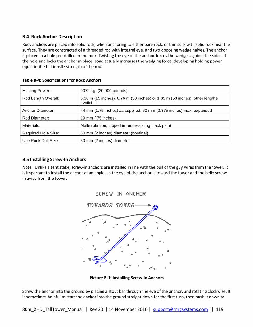
80m_XHD_TallTower_Manual | Rev 20 | 14 November 2016 | [email protected] || 119
B.4 Rock Anchor Description
Rock anchors are placed into solid rock, when anchoring to either bare rock, or thin soils with solid rock near the surface. They are constructed of a threaded rod with integral eye, and two opposing wedge halves. The anchor is placed in a hole pre-drilled in the rock. Twisting the eye of the anchor forces the wedges against the sides of the hole and locks the anchor in place. Load actually increases the wedging force, developing holding power equal to the full tensile strength of the rod.
Table B-4: Specifications for Rock Anchors
Holding Power: 9072 kgf (20,000 pounds)
Rod Length Overall: 0.38 m (15 inches), 0.76 m (30 inches) or 1.35 m (53 inches), other lengths available
Anchor Diameter: 44 mm (1.75 inches) as supplied, 60 mm (2.375 inches) max. expanded
Rod Diameter: 19 mm (.75 inches)
Materials: Malleable iron, dipped in rust-resisting black paint
Required Hole Size: 50 mm (2 inches) diameter (nominal)
Use Rock Drill Size: 50 mm (2 inches) diameter
B.5 Installing Screw-In Anchors
Note: Unlike a tent stake, screw-in anchors are installed in line with the pull of the guy wires from the tower. It is important to install the anchor at an angle, so the eye of the anchor is toward the tower and the helix screws in away from the tower.
Picture B-1: Installing Screw-in Anchors
Screw the anchor into the ground by placing a stout bar through the eye of the anchor, and rotating clockwise. It is sometimes helpful to start the anchor into the ground straight down for the first turn, then push it down to

80m_XHD_TallTower_Manual | Rev 20 | 14 November 2016 | [email protected] || 120
the correct angle and complete the installation. Continue screwing the anchor into the ground until about 150 mm (6 inches) of the anchor rod remains above the ground. If the anchor cannot be installed due to rocks in the soil, or other obstacles, try placing the anchor as much as 1 m (3 feet) from its ideal position to avoid the obstacle, or replace the screw-in anchor with the correct anchor for the soil. Arrowhead anchors are often suitable for rocky soils. If necessary, a hole can be dug for the screw-in anchor to the proper installed depth, the anchor placed in the hole, and the hole back-filled. The earth must be tamped onto the anchor hard while back filling. The holding power of an anchor placed this way will not be as great as an anchor screwed into undisturbed soil. If in doubt, get professional advice on whether this option will work for your site.
B.6 Installing 8 inch diameter twin helix anchors
The installation of the 8 inch diameter twin helix anchors requires machinery capable of delivering working torques of 8135 N-m (6000 ft-lbf). NOTE: All sixteen (16) 8 inch diameter twin helix anchors employed on the 80 m XHD TallTower must be pull tested to 6804 kgf (15,000 lbf). Note: It is important to install the anchor at an angle, so the eye of the anchor is toward the tower and the twin helix anchor points away from the tower. If the anchor is incorrectly installed straight into the ground, the load will bend the rod and pull it through the ground, allowing the guys to go slack. The installation tools required to install the twin helix anchors are shown below.
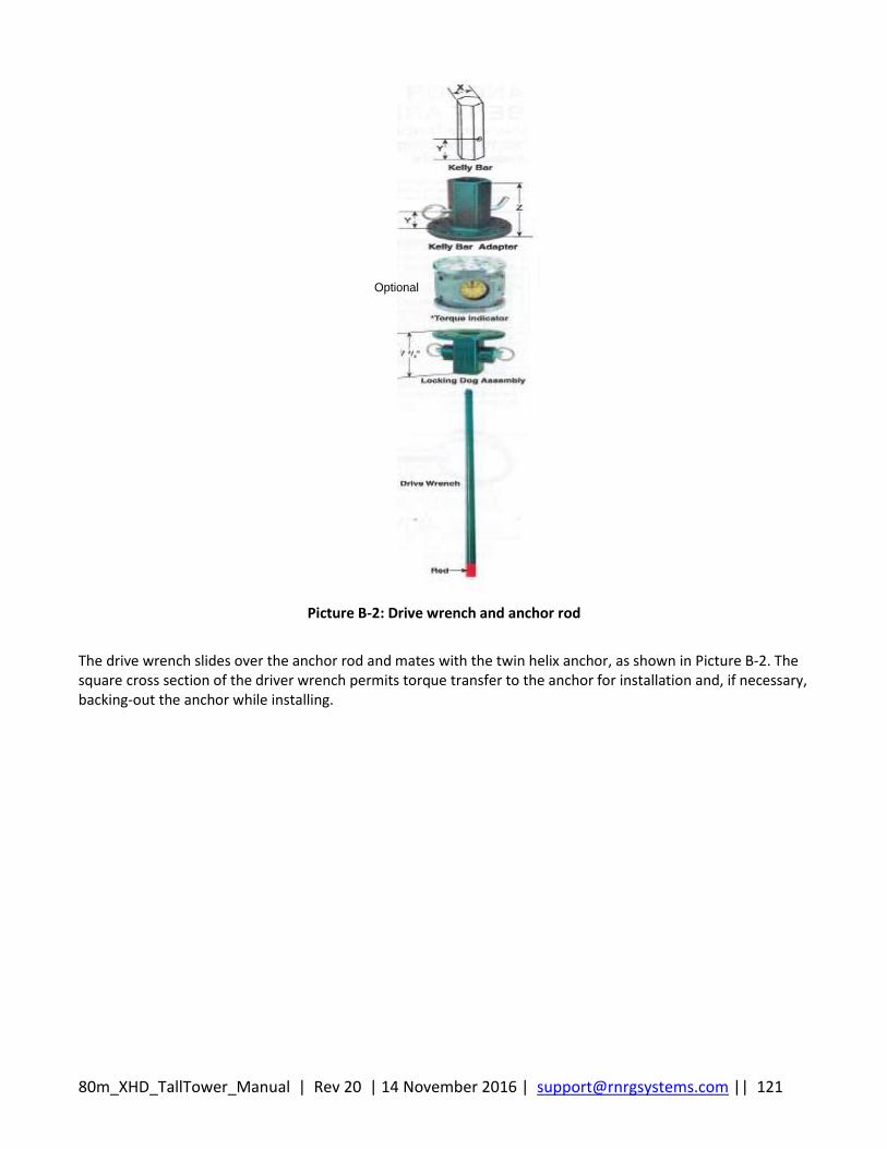
80m_XHD_TallTower_Manual | Rev 20 | 14 November 2016 | [email protected] || 121
Optional
Picture B-2: Drive wrench and anchor rod
The drive wrench slides over the anchor rod and mates with the twin helix anchor, as shown in Picture B-2. The square cross section of the driver wrench permits torque transfer to the anchor for installation and, if necessary, backing-out the anchor while installing.
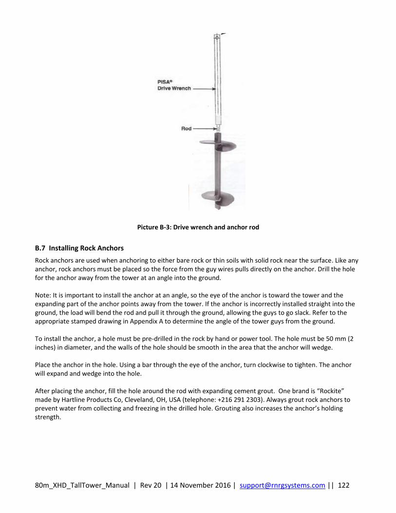
80m_XHD_TallTower_Manual | Rev 20 | 14 November 2016 | [email protected] || 122
Picture B-3: Drive wrench and anchor rod
B.7 Installing Rock Anchors
Rock anchors are used when anchoring to either bare rock or thin soils with solid rock near the surface. Like any anchor, rock anchors must be placed so the force from the guy wires pulls directly on the anchor. Drill the hole for the anchor away from the tower at an angle into the ground. Note: It is important to install the anchor at an angle, so the eye of the anchor is toward the tower and the expanding part of the anchor points away from the tower. If the anchor is incorrectly installed straight into the ground, the load will bend the rod and pull it through the ground, allowing the guys to go slack. Refer to the appropriate stamped drawing in Appendix A to determine the angle of the tower guys from the ground. To install the anchor, a hole must be pre-drilled in the rock by hand or power tool. The hole must be 50 mm (2 inches) in diameter, and the walls of the hole should be smooth in the area that the anchor will wedge. Place the anchor in the hole. Using a bar through the eye of the anchor, turn clockwise to tighten. The anchor will expand and wedge into the hole. After placing the anchor, fill the hole around the rod with expanding cement grout. One brand is “Rockite” made by Hartline Products Co, Cleveland, OH, USA (telephone: +216 291 2303). Always grout rock anchors to prevent water from collecting and freezing in the drilled hole. Grouting also increases the anchor’s holding strength.

80m_XHD_TallTower_Manual | Rev 20 | 14 November 2016 | [email protected] || 123
Appendix C: Site Visit Procedures
C.1 Site Checklist
When making a site visit, check the following:
Make sure the tower is straight. Stand at the base of the tower and look up to identify any
bowed sections or curves in the tower that may have developed since the tower installation.
Carefully adjust guy wires as necessary to straighten the tower.
Check guy wires for excessive slack and adjust as necessary following the section entitled
Adjusting Guy Wires.
It is normal for guy wires to stretch over time, and it is especially important to adjust them
before they are subjected to icing or high winds.
Check each anchor for movement or loosening. A loose anchor can also cause excessive slack in
guy wires.
Check that mounting booms, cellular antennas, temperature sensors, etc. are securely attached.
Confirm that all grounding connections on the tower and on the logger are secure and haven’t
corroded.
Check instantaneous sensor readings on each channel of your data logger. Any sensor providing
erroneous readings should be disconnected from the logger and tested independently and/or
replaced. It is a good idea to always have spare sensors, memory cards, batteries, and a spare
data logger!
Change the data logger’s batteries. Remember that batteries are cheap, and old batteries can
leak – it’s better to change them prematurely rather than risk losing data or damaging your
measurement equipment!

80m_XHD_TallTower_Manual | Rev 20 | 14 November 2016 | [email protected] || 124
Appendix D: 80m XHD TallTower Painted Version
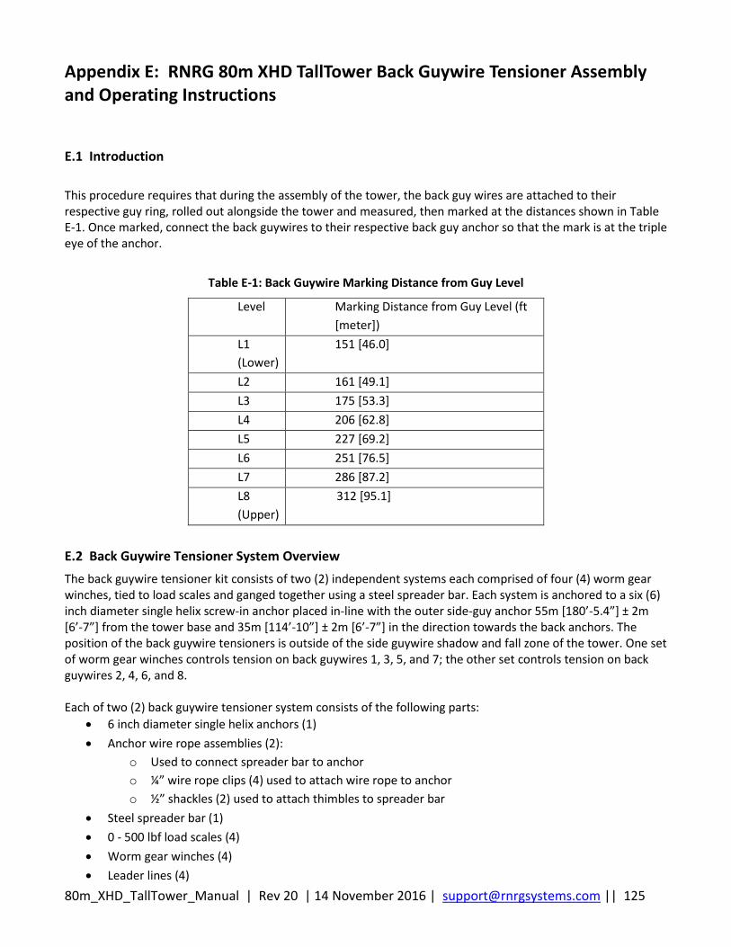
80m_XHD_TallTower_Manual | Rev 20 | 14 November 2016 | [email protected] || 125
Appendix E: RNRG 80m XHD TallTower Back Guywire Tensioner Assembly and Operating Instructions
E.1 Introduction
This procedure requires that during the assembly of the tower, the back guy wires are attached to their respective guy ring, rolled out alongside the tower and measured, then marked at the distances shown in Table E-1. Once marked, connect the back guywires to their respective back guy anchor so that the mark is at the triple eye of the anchor.
Table E-1: Back Guywire Marking Distance from Guy Level
Level Marking Distance from Guy Level (ft
[meter])
L1
(Lower)
151 [46.0]
L2 161 [49.1]
L3 175 [53.3]
L4 206 [62.8]
L5 227 [69.2]
L6 251 [76.5]
L7 286 [87.2]
L8
(Upper)
312 [95.1]
E.2 Back Guywire Tensioner System Overview
The back guywire tensioner kit consists of two (2) independent systems each comprised of four (4) worm gear winches, tied to load scales and ganged together using a steel spreader bar. Each system is anchored to a six (6) inch diameter single helix screw-in anchor placed in-line with the outer side-guy anchor 55m [180’-5.4”] ± 2m [6’-7”] from the tower base and 35m [114’-10”] ± 2m [6’-7”] in the direction towards the back anchors. The position of the back guywire tensioners is outside of the side guywire shadow and fall zone of the tower. One set of worm gear winches controls tension on back guywires 1, 3, 5, and 7; the other set controls tension on back guywires 2, 4, 6, and 8. Each of two (2) back guywire tensioner system consists of the following parts:
6 inch diameter single helix anchors (1)
Anchor wire rope assemblies (2):
o Used to connect spreader bar to anchor
o ¼” wire rope clips (4) used to attach wire rope to anchor
o ½” shackles (2) used to attach thimbles to spreader bar
Steel spreader bar (1)
0 - 500 lbf load scales (4)
Worm gear winches (4)
Leader lines (4)
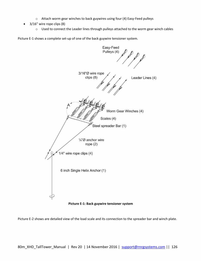
80m_XHD_TallTower_Manual | Rev 20 | 14 November 2016 | [email protected] || 126
o Attach worm gear winches to back guywires using four (4) Easy-Feed pulleys
3/16” wire rope clips (8)
o Used to connect the Leader lines through pulleys attached to the worm gear winch cables
Picture E-1 shows a complete set-up of one of the back guywire tensioner system.
Picture E-1: Back guywire tensioner system
Picture E-2 shows are detailed view of the load scale and its connection to the spreader bar and winch plate.
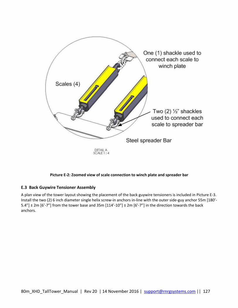
80m_XHD_TallTower_Manual | Rev 20 | 14 November 2016 | [email protected] || 127
Picture E-2: Zoomed view of scale connection to winch plate and spreader bar
E.3 Back Guywire Tensioner Assembly
A plan view of the tower layout showing the placement of the back guywire tensioners is included in Picture E-3. Install the two (2) 6 inch diameter single helix screw-in anchors in-line with the outer side-guy anchor 55m [180’-5.4”] ± 2m [6’-7”] from the tower base and 35m [114’-10”] ± 2m [6’-7”] in the direction towards the back anchors.
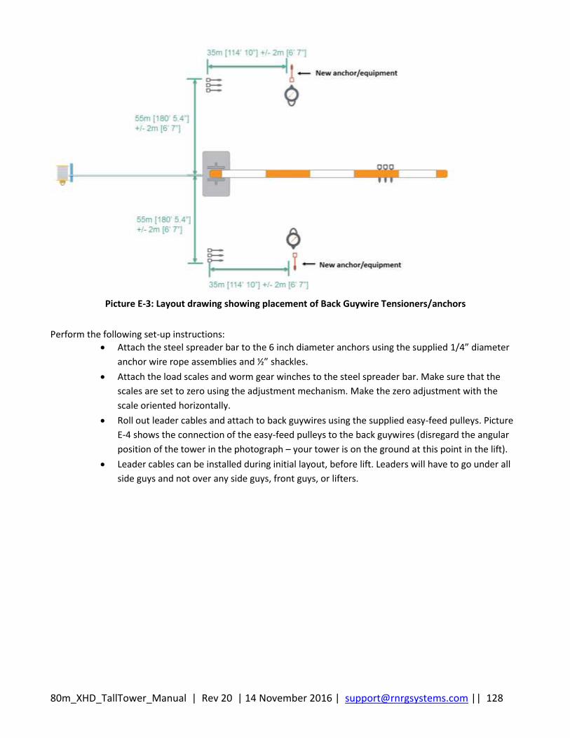
80m_XHD_TallTower_Manual | Rev 20 | 14 November 2016 | [email protected] || 128
Picture E-3: Layout drawing showing placement of Back Guywire Tensioners/anchors
Perform the following set-up instructions:
Attach the steel spreader bar to the 6 inch diameter anchors using the supplied 1/4” diameter
anchor wire rope assemblies and ½” shackles.
Attach the load scales and worm gear winches to the steel spreader bar. Make sure that the
scales are set to zero using the adjustment mechanism. Make the zero adjustment with the
scale oriented horizontally.
Roll out leader cables and attach to back guywires using the supplied easy-feed pulleys. Picture
E-4 shows the connection of the easy-feed pulleys to the back guywires (disregard the angular
position of the tower in the photograph – your tower is on the ground at this point in the lift).
Leader cables can be installed during initial layout, before lift. Leaders will have to go under all
side guys and not over any side guys, front guys, or lifters.
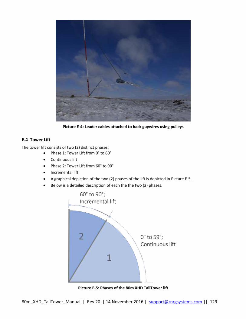
80m_XHD_TallTower_Manual | Rev 20 | 14 November 2016 | [email protected] || 129
Picture E-4: Leader cables attached to back guywires using pulleys
E.4 Tower Lift
The tower lift consists of two (2) distinct phases:
Phase 1: Tower Lift from 0° to 60°
Continuous lift
Phase 2: Tower Lift from 60° to 90°
Incremental lift
A graphical depiction of the two (2) phases of the lift is depicted in Picture E-5.
Below is a detailed description of each the the two (2) phases.
Picture E-5: Phases of the 80m XHD TallTower lift

80m_XHD_TallTower_Manual | Rev 20 | 14 November 2016 | [email protected] || 130
E.4.1 Phase 1: Tower Lift from 0° to 60°
Raise the tower from 0° to 60° following the same procedure described in the RNRG 80 meter XHD TallTower™ Installation Manual & Specifications.
E.4.2 Phase 2: Tower Lift from 60° to 90°
Above 60° from horizontal, the tower is raised incrementally using the Back Guywire Tensioner system following a revised Lift Cycle described below. The worm gear tensioners replace personnel applying resistance using ropes and carabiners to the back guywires. The Back Guywire Tensioner system also replaces the Lift-Slack (i.e., “Inch-Worm”) method. Allocate the crew to perform the following tasks:
Crew Leader (1) to monitor and supervise the tower lift, monitor back guy wire tension at end of lift
Crew member to monitor and control worm gear winch back guywire tensioners (2)
Crew member to monitor and control side guywire tension (2)
Crew member to operate winch (1)
When the tower is at 60 degrees from horizontal, stop the lift. As shown in Picture E-7, attach the leader lines to the worm gear winches using the following instructions:
Using a cordless drill with a ¾” nut driver, reel out the worm gear winch line about 10 feet and attach
the leader cable.
Feed the leader line cable through the easy-feed pulley affixed to the worm gear winch. Keep some
tension on the winch line to prevent unspooling.
Remove slack and secure the leader line with the supplied wire rope clips. Run winch as-required to
place tension (40 ± 10 lbf) on the cable. Attach all eight (8) worm gear winches in the same manner.
Refer to Picture E-7, Picture E-8, and Picture E-9 for graphical and pictorial details.
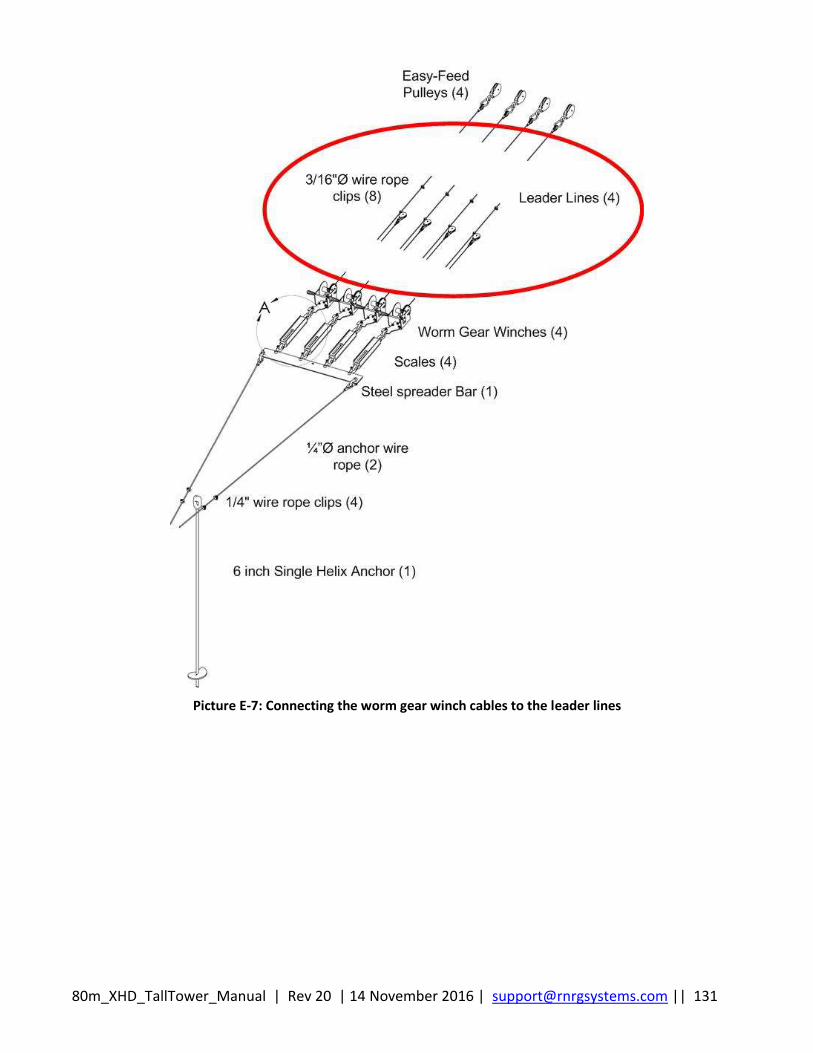
80m_XHD_TallTower_Manual | Rev 20 | 14 November 2016 | [email protected] || 131
Picture E-7: Connecting the worm gear winch cables to the leader lines
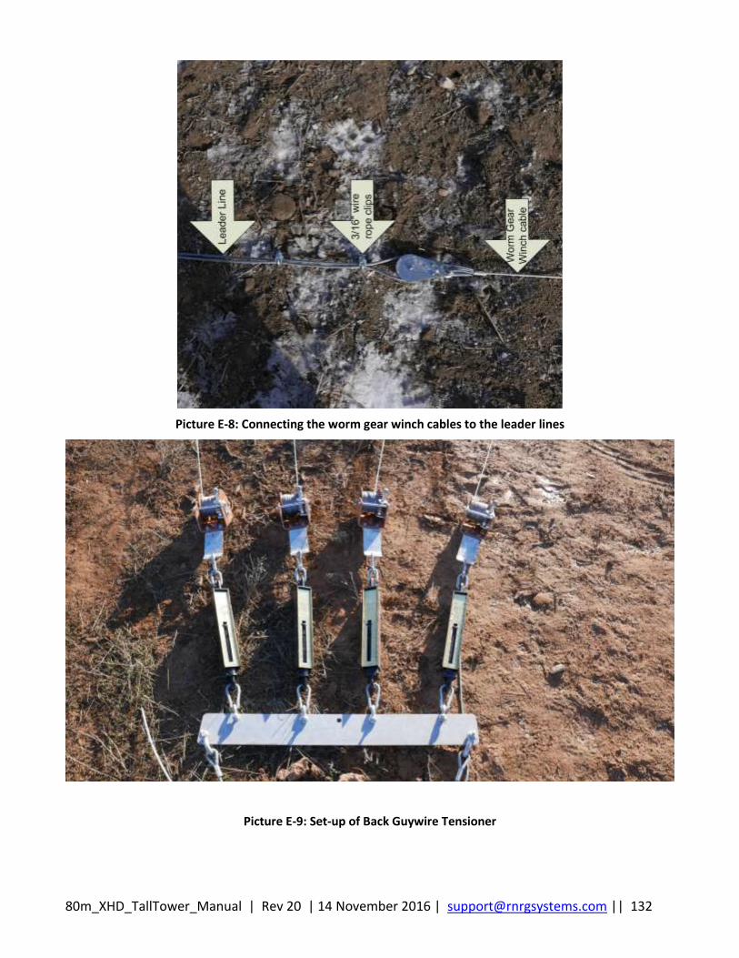
80m_XHD_TallTower_Manual | Rev 20 | 14 November 2016 | [email protected] || 132
Picture E-8: Connecting the worm gear winch cables to the leader lines
Picture E-9: Set-up of Back Guywire Tensioner
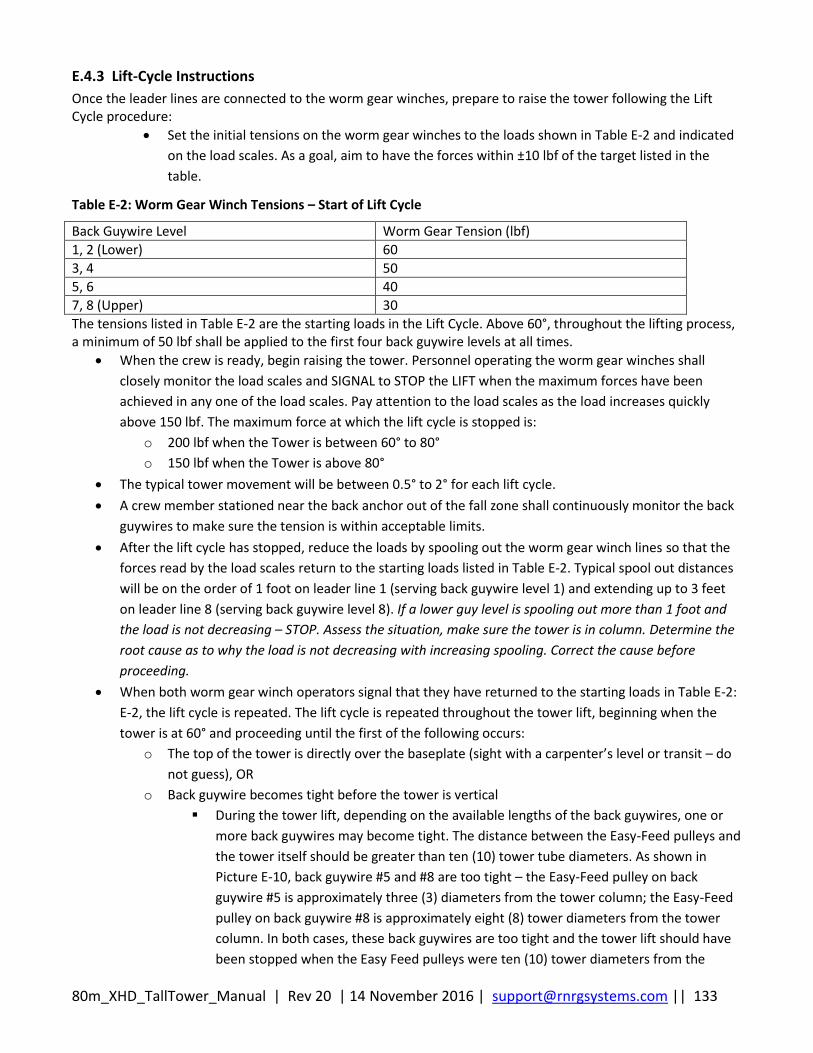
80m_XHD_TallTower_Manual | Rev 20 | 14 November 2016 | [email protected] || 133
E.4.3 Lift-Cycle Instructions
Once the leader lines are connected to the worm gear winches, prepare to raise the tower following the Lift Cycle procedure:
Set the initial tensions on the worm gear winches to the loads shown in Table E-2 and indicated
on the load scales. As a goal, aim to have the forces within ±10 lbf of the target listed in the
table.
Table E-2: Worm Gear Winch Tensions – Start of Lift Cycle
Back Guywire Level Worm Gear Tension (lbf)
1, 2 (Lower) 60
3, 4 50
5, 6 40
7, 8 (Upper) 30
The tensions listed in Table E-2 are the starting loads in the Lift Cycle. Above 60°, throughout the lifting process, a minimum of 50 lbf shall be applied to the first four back guywire levels at all times.
When the crew is ready, begin raising the tower. Personnel operating the worm gear winches shall
closely monitor the load scales and SIGNAL to STOP the LIFT when the maximum forces have been
achieved in any one of the load scales. Pay attention to the load scales as the load increases quickly
above 150 lbf. The maximum force at which the lift cycle is stopped is:
o 200 lbf when the Tower is between 60° to 80°
o 150 lbf when the Tower is above 80°
The typical tower movement will be between 0.5° to 2° for each lift cycle.
A crew member stationed near the back anchor out of the fall zone shall continuously monitor the back
guywires to make sure the tension is within acceptable limits.
After the lift cycle has stopped, reduce the loads by spooling out the worm gear winch lines so that the
forces read by the load scales return to the starting loads listed in Table E-2. Typical spool out distances
will be on the order of 1 foot on leader line 1 (serving back guywire level 1) and extending up to 3 feet
on leader line 8 (serving back guywire level 8). If a lower guy level is spooling out more than 1 foot and
the load is not decreasing – STOP. Assess the situation, make sure the tower is in column. Determine the
root cause as to why the load is not decreasing with increasing spooling. Correct the cause before
proceeding.
When both worm gear winch operators signal that they have returned to the starting loads in Table E-2:
E-2, the lift cycle is repeated. The lift cycle is repeated throughout the tower lift, beginning when the
tower is at 60° and proceeding until the first of the following occurs:
o The top of the tower is directly over the baseplate (sight with a carpenter’s level or transit – do
not guess), OR
o Back guywire becomes tight before the tower is vertical
During the tower lift, depending on the available lengths of the back guywires, one or
more back guywires may become tight. The distance between the Easy-Feed pulleys and
the tower itself should be greater than ten (10) tower tube diameters. As shown in
Picture E-10, back guywire #5 and #8 are too tight – the Easy-Feed pulley on back
guywire #5 is approximately three (3) diameters from the tower column; the Easy-Feed
pulley on back guywire #8 is approximately eight (8) tower diameters from the tower
column. In both cases, these back guywires are too tight and the tower lift should have
been stopped when the Easy Feed pulleys were ten (10) tower diameters from the
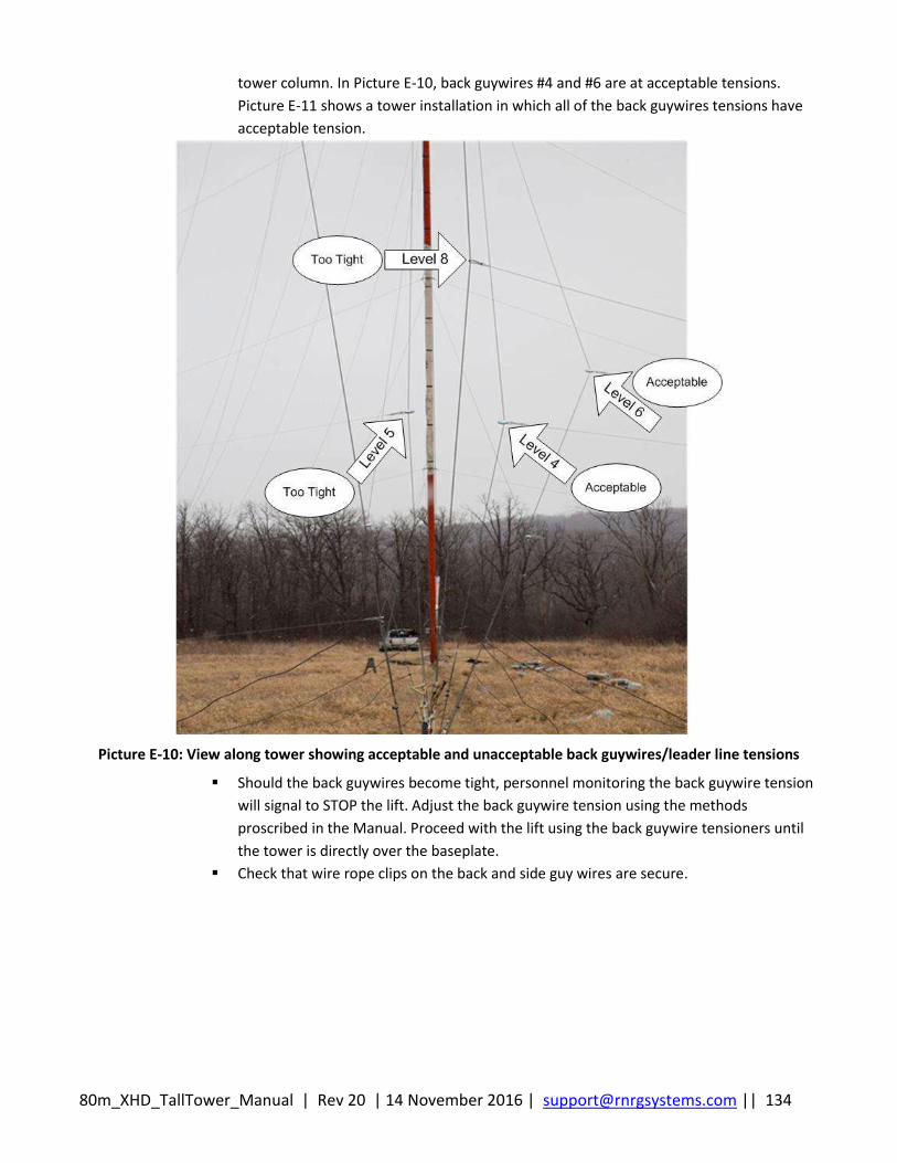
80m_XHD_TallTower_Manual | Rev 20 | 14 November 2016 | [email protected] || 134
tower column. In Picture E-10, back guywires #4 and #6 are at acceptable tensions.
Picture E-11 shows a tower installation in which all of the back guywires tensions have
acceptable tension.
Picture E-10: View along tower showing acceptable and unacceptable back guywires/leader line tensions
Should the back guywires become tight, personnel monitoring the back guywire tension
will signal to STOP the lift. Adjust the back guywire tension using the methods
proscribed in the Manual. Proceed with the lift using the back guywire tensioners until
the tower is directly over the baseplate.
Check that wire rope clips on the back and side guy wires are secure.
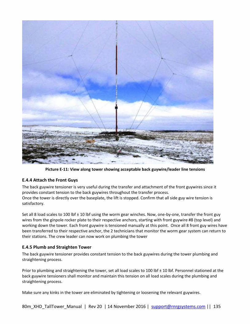
80m_XHD_TallTower_Manual | Rev 20 | 14 November 2016 | [email protected] || 135
Picture E-11: View along tower showing acceptable back guywire/leader line tensions
E.4.4 Attach the Front Guys
The back guywire tensioner is very useful during the transfer and attachment of the front guywires since it provides constant tension to the back guywires throughout the transfer process. Once the tower is directly over the baseplate, the lift is stopped. Confirm that all side guy wire tension is satisfactory. Set all 8 load scales to 100 lbf ± 10 lbf using the worm gear winches. Now, one-by-one, transfer the front guy wires from the ginpole rocker plate to their respective anchors, starting with front guywire #8 (top level) and working down the tower. Each front guywire is tensioned manually at this point. Once all 8 front guy wires have been transferred to their respective anchor, the 2 technicians that monitor the worm gear system can return to their stations. The crew leader can now work on plumbing the tower
E.4.5 Plumb and Straighten Tower
The back guywire tensioner provides constant tension to the back guywires during the tower plumbing and straightening process. Prior to plumbing and straightening the tower, set all load scales to 100 lbf ± 10 lbf. Personnel stationed at the back guywire tensioners shall monitor and maintain this tension on all load scales during the plumbing and straightening process. Make sure any kinks in the tower are eliminated by tightening or loosening the relevant guywires.
80m_XHD_TallTower_Manual | Rev 20 | 14 November 2016 | [email protected] || 136
Once kinks have been removed, proceed to plumb and straighten the tower. Using a carpenter or digital level, measure the verticality of the base tube. Adjust the lower level guy wires as needed until the base tube is vertical (90° ± 0.5°). It may take multiple adjustments from the bottom to the top of the tower before the tower is completely plumb. Starting with level 1 and working your way up the tower, have 2-3 technicians working at the front anchors utilizing Chicago grips and come-alongs to tension the guy wires. First set level #1 back guy tension to 60 lbf using the worm gear, then pull in on the front guy wire to straighten the tower. As level 1 front guy wire is being tensioned, the scale measuring the back guy wire for level 1 will increase. Slowly feather the worm gear on the back guy wire to remain at 60 lbf while the front guy wire is tensioned. Once you achieve the desired tower location for level one, lock down the front guy wire at the anchor point with the correct wire rope clips and re-tension the scale on the back guy wire to 100lbf. Move to level 2 and repeat the same process. It may be necessary to skip guy levels and work on a particular level that is too far out of alignment. You should always try to keep the tower as straight as possible while plumbing the tower. You will notice that the levels above the one you are working on will increase their tension as you plumb the tower. Keep tensions at 150 lbf or below if they try to spike to higher tensions. When the tower is plumb, set up on the back anchors with a come-along and Chicago grip. One level at a time, pull in the slack on the back guy wire while letting out on the worm gear, until the easy feed pulley is no longer holding the back guy wire. Remove pulley and fasten guy wire to anchor at the correct pulse method tension. When the tower is plumb, all guywires shall be properly tensioned mechanically and tested using the pulse method for guy tension. See manual for proper pulse method guy tensions.
E.5 Lowering the tower
Opposite procedure would be performed. Tension all 8 back guy wires to the maximum tension (150 lbf between 90° and 80°. Lowering the tower until the minimum tension is achieved based on Table 1 above. Then re-tension all 8 lines to maximum tension again. From 80° to 60° the maximum tension is 200lbf. Once the tower is lowered down to 60° back tensioners are no longer needed. Side guy wire tension, on the other hand, needs to be monitored throughout the entire lowering process.
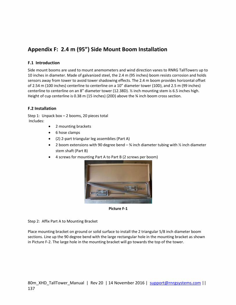
80m_XHD_TallTower_Manual | Rev 20 | 14 November 2016 | [email protected] || 137
Appendix F: 2.4 m (95”) Side Mount Boom Installation
F.1 Introduction
Side mount booms are used to mount anemometers and wind direction vanes to RNRG TallTowers up to 10 inches in diameter. Made of galvanized steel, the 2.4 m (95 inches) boom resists corrosion and holds sensors away from tower to avoid tower shadowing effects. The 2.4 m boom provides horizontal offset of 2.54 m (100 inches) centerline to centerline on a 10” diameter tower (10D), and 2.5 m (99 inches) centerline to centerline on an 8” diameter tower (12.38D). ½ inch mounting stem is 6.5 inches high. Height of cup centerline is 0.38 m (15 inches) (20D) above the ¾ inch boom cross section.
F.2 Installation
Step 1: Unpack box – 2 booms, 20 pieces total Includes:
2 mounting brackets
6 hose clamps
(2) 2-part triangular leg assemblies (Part A)
2 boom extensions with 90 degree bend – ¾ inch diameter tubing with ½ inch diameter
stem shaft (Part B)
4 screws for mounting Part A to Part B (2 screws per boom)
Picture F-1
Step 2: Affix Part A to Mounting Bracket Place mounting bracket on ground or solid surface to install the 2 triangular 5/8 inch diameter boom sections. Line up the 90 degree bend with the large rectangular hole in the mounting bracket as shown in Picture F-2. The large hole in the mounting bracket will go towards the top of the tower.
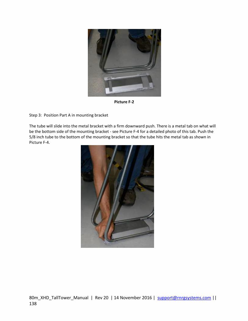
80m_XHD_TallTower_Manual | Rev 20 | 14 November 2016 | [email protected] || 138
Picture F-2
Step 3: Position Part A in mounting bracket The tube will slide into the metal bracket with a firm downward push. There is a metal tab on what will be the bottom side of the mounting bracket - see Picture F-4 for a detailed photo of this tab. Push the 5/8 inch tube to the bottom of the mounting bracket so that the tube hits the metal tab as shown in Picture F-4.
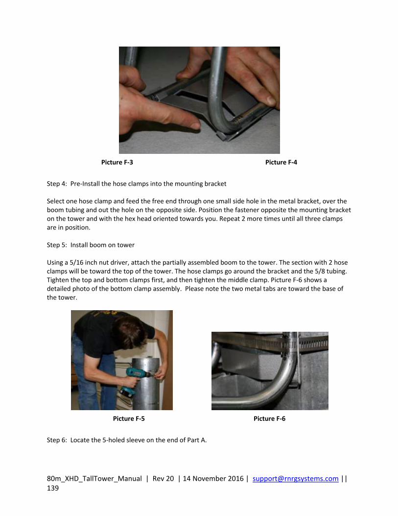
80m_XHD_TallTower_Manual | Rev 20 | 14 November 2016 | [email protected] || 139
Picture F-3 Picture F-4
Step 4: Pre-Install the hose clamps into the mounting bracket Select one hose clamp and feed the free end through one small side hole in the metal bracket, over the boom tubing and out the hole on the opposite side. Position the fastener opposite the mounting bracket on the tower and with the hex head oriented towards you. Repeat 2 more times until all three clamps are in position. Step 5: Install boom on tower Using a 5/16 inch nut driver, attach the partially assembled boom to the tower. The section with 2 hose clamps will be toward the top of the tower. The hose clamps go around the bracket and the 5/8 tubing. Tighten the top and bottom clamps first, and then tighten the middle clamp. Picture F-6 shows a detailed photo of the bottom clamp assembly. Please note the two metal tabs are toward the base of the tower.
Picture F-5 Picture F-6
Step 6: Locate the 5-holed sleeve on the end of Part A.
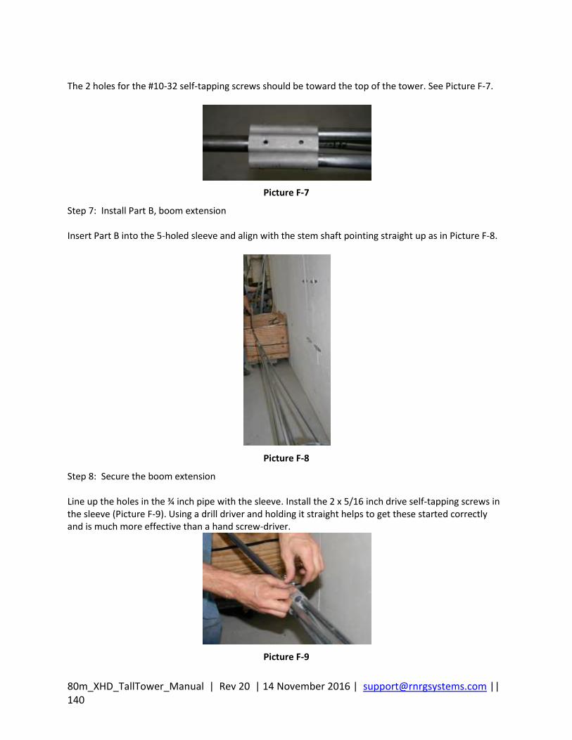
80m_XHD_TallTower_Manual | Rev 20 | 14 November 2016 | [email protected] || 140
The 2 holes for the #10-32 self-tapping screws should be toward the top of the tower. See Picture F-7.
Picture F-7
Step 7: Install Part B, boom extension Insert Part B into the 5-holed sleeve and align with the stem shaft pointing straight up as in Picture F-8.
Picture F-8
Step 8: Secure the boom extension Line up the holes in the ¾ inch pipe with the sleeve. Install the 2 x 5/16 inch drive self-tapping screws in the sleeve (Picture F-9). Using a drill driver and holding it straight helps to get these started correctly and is much more effective than a hand screw-driver.
Picture F-9
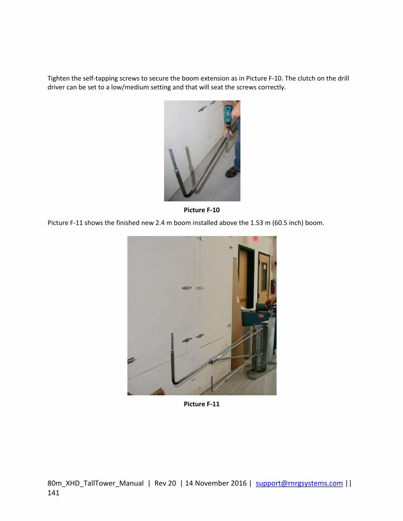
80m_XHD_TallTower_Manual | Rev 20 | 14 November 2016 | [email protected] || 141
Tighten the self-tapping screws to secure the boom extension as in Picture F-10. The clutch on the drill driver can be set to a low/medium setting and that will seat the screws correctly.
Picture F-10
Picture F-11 shows the finished new 2.4 m boom installed above the 1.53 m (60.5 inch) boom.
Picture F-11

80m_XHD_TallTower_Manual | Rev 20 | 14 November 2016 | [email protected] || 142
Appendix G: Aligning Wind Vanes
G.1 Introduction
Wind Vanes measure wind direction relative to the orientation of the fixed base on the sensor. This Application Note gives you the information you need to orient your wind vanes correctly when they are mounted to the tower. This note also includes information on using Offset and Magnetic Declination corrections when scaling your data to obtain properly scaled and oriented data.
G.2 Magnetic Declination
Since the earth’s magnetic field is not uniform, the magnetic poles do not coincide with the true geographic poles. Moreover, a compass generally doesn’t point to a true geographic pole; it points to a magnetic pole. This difference between a true geographic bearing and a magnetic bearing varies from location to location and is called magnetic declination. Magnetic declination or “compass variation” is the horizontal angle between true north (also called “geographic north” or “map north”) and the direction the compass points, magnetic north. Magnetic declination is measured as the number of degrees of error a compass shows at a site. The declination for sites located east of the magnetic north pole is expressed as the number of degrees that magnetic north is west of true north. The declination for sites located west of the magnetic north pole is expressed as the number of degrees that magnetic north is east of true north. For example, Vermont (USA) has a magnetic declination of 15 degrees west. In other words, magnetic north in Vermont is 15 degrees to the west of true north. Magnetic north in Fairbanks, Alaska (USA) is about 27 degrees east of true north; therefore, its magnetic declination is 27 degrees east. The earth’s magnetic field varies slightly in position over time. Therefore, the magnetic declination at a site also varies over time. Because of this variation, it is important that you reference an up-to-date map of declination (“isogonic map”) if you choose to orient your wind vanes to magnetic north. Later you can enter a correction for magnetic declination into your wind data analysis software if desired.
G.3 Mounting and Aligning Wind Vanes
Since a magnetic compass is the simplest direction reference, it is sometimes convenient to orient wind vanes in the field to magnetic north. Most RNRG customers, however, align their wind vanes to true north. Before installing your RNRG logger, decide whether you want wind direction data to report north when the wind is from the magnetic north or when the wind is from true north. Be sure to make note of your choice and maintain consistency among your sites and projects. To align a wind vane to true north:
1. Use a transparent orienteering compass with a rotating bezel and magnetic declination
markings. In the example in Picture G-1, 15 degrees west means that the direction of the
compass needle (magnetic north) lies 15 degrees west of true north.
[Type a quote from the document or the summary of an interesting point. You can position the text box anywhere in the document. Use the Text Box Tools tab to change the formatting of the pull quote text box.]
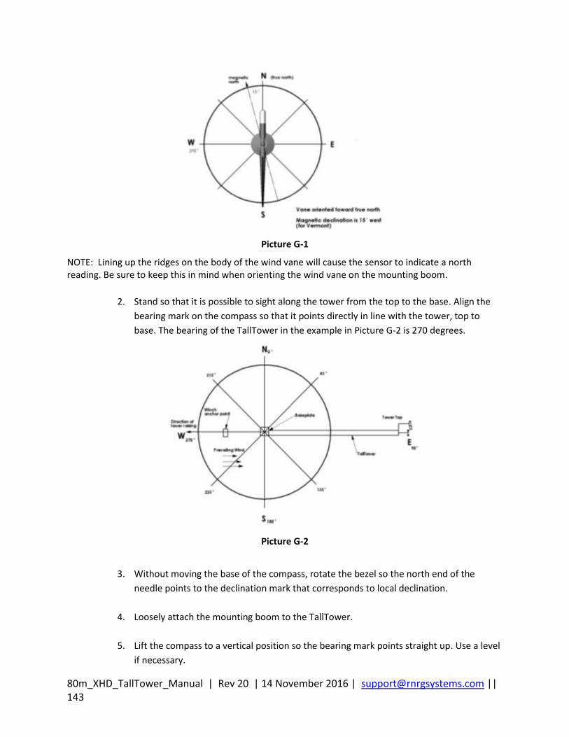
80m_XHD_TallTower_Manual | Rev 20 | 14 November 2016 | [email protected] || 143
Picture G-1
NOTE: Lining up the ridges on the body of the wind vane will cause the sensor to indicate a north reading. Be sure to keep this in mind when orienting the wind vane on the mounting boom.
2. Stand so that it is possible to sight along the tower from the top to the base. Align the
bearing mark on the compass so that it points directly in line with the tower, top to
base. The bearing of the TallTower in the example in Picture G-2 is 270 degrees.
Picture G-2
3. Without moving the base of the compass, rotate the bezel so the north end of the
needle points to the declination mark that corresponds to local declination.
4. Loosely attach the mounting boom to the TallTower.
5. Lift the compass to a vertical position so the bearing mark points straight up. Use a level
if necessary.
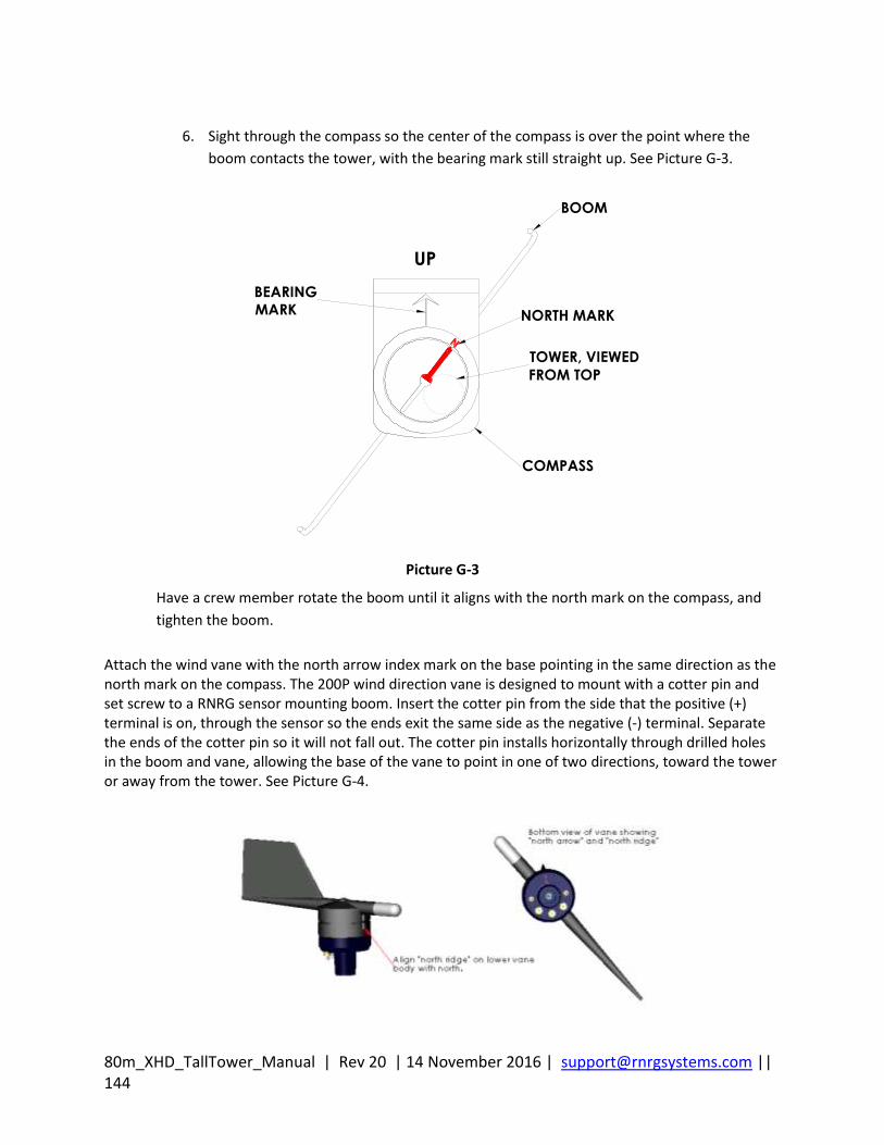
80m_XHD_TallTower_Manual | Rev 20 | 14 November 2016 | [email protected] || 144
6. Sight through the compass so the center of the compass is over the point where the
boom contacts the tower, with the bearing mark still straight up. See Picture G-3.
Picture G-3
Have a crew member rotate the boom until it aligns with the north mark on the compass, and
tighten the boom.
Attach the wind vane with the north arrow index mark on the base pointing in the same direction as the north mark on the compass. The 200P wind direction vane is designed to mount with a cotter pin and set screw to a RNRG sensor mounting boom. Insert the cotter pin from the side that the positive (+) terminal is on, through the sensor so the ends exit the same side as the negative (-) terminal. Separate the ends of the cotter pin so it will not fall out. The cotter pin installs horizontally through drilled holes in the boom and vane, allowing the base of the vane to point in one of two directions, toward the tower or away from the tower. See Picture G-4.
BOOM
NORTH MARK
TOWER, VIEWED
FROM TOP
COMPASS
BEARING
MARK
UP
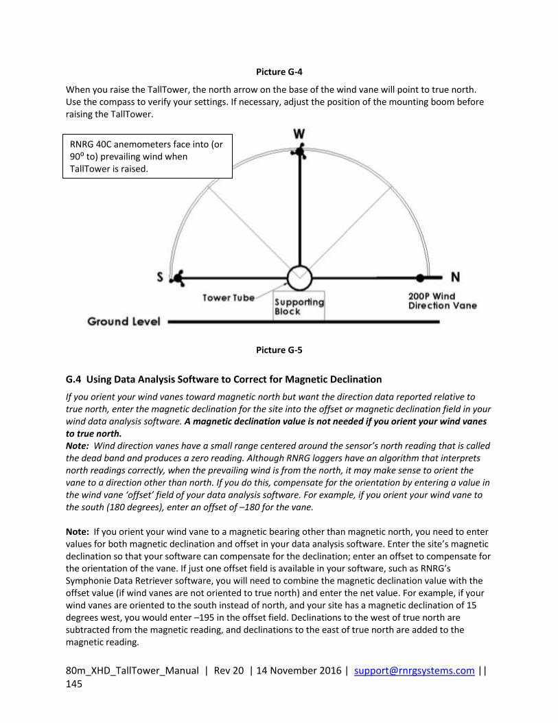
80m_XHD_TallTower_Manual | Rev 20 | 14 November 2016 | [email protected] || 145
Picture G-4
When you raise the TallTower, the north arrow on the base of the wind vane will point to true north. Use the compass to verify your settings. If necessary, adjust the position of the mounting boom before raising the TallTower.
Picture G-5
G.4 Using Data Analysis Software to Correct for Magnetic Declination
If you orient your wind vanes toward magnetic north but want the direction data reported relative to true north, enter the magnetic declination for the site into the offset or magnetic declination field in your wind data analysis software. A magnetic declination value is not needed if you orient your wind vanes to true north. Note: Wind direction vanes have a small range centered around the sensor’s north reading that is called the dead band and produces a zero reading. Although RNRG loggers have an algorithm that interprets north readings correctly, when the prevailing wind is from the north, it may make sense to orient the vane to a direction other than north. If you do this, compensate for the orientation by entering a value in the wind vane ‘offset’ field of your data analysis software. For example, if you orient your wind vane to the south (180 degrees), enter an offset of –180 for the vane. Note: If you orient your wind vane to a magnetic bearing other than magnetic north, you need to enter values for both magnetic declination and offset in your data analysis software. Enter the site’s magnetic declination so that your software can compensate for the declination; enter an offset to compensate for the orientation of the vane. If just one offset field is available in your software, such as RNRG’s Symphonie Data Retriever software, you will need to combine the magnetic declination value with the offset value (if wind vanes are not oriented to true north) and enter the net value. For example, if your wind vanes are oriented to the south instead of north, and your site has a magnetic declination of 15 degrees west, you would enter –195 in the offset field. Declinations to the west of true north are subtracted from the magnetic reading, and declinations to the east of true north are added to the magnetic reading.
RNRG 40C anemometers face into (or 90⁰ to) prevailing wind when TallTower is raised.
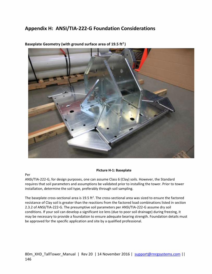
80m_XHD_TallTower_Manual | Rev 20 | 14 November 2016 | [email protected] || 146
Appendix H: ANSI/TIA-222-G Foundation Considerations
Baseplate Geometry (with ground surface area of 19.5 ft2 )
Per ANSI/TIA-222-G, for design purposes, one can assume Class 6 (Clay) soils. However, the Standard requires that soil parameters and assumptions be validated prior to installing the tower. Prior to tower installation, determine the soil type, preferably through soil sampling. The baseplate cross-sectional area is 19.5 ft2. The cross-sectional area was sized to ensure the factored resistance of Clay soil is greater than the reactions from the factored load combinations listed in section 2.3.2 of ANSI/TIA-222-G. The presumptive soil parameters per ANSI/TIA-222-G assume dry soil conditions. If your soil can develop a significant ice lens (due to poor soil drainage) during freezing, it may be necessary to provide a foundation to ensure adequate bearing strength. Foundation details must be approved for the specific application and site by a qualified professional.
Picture H-1: Baseplate
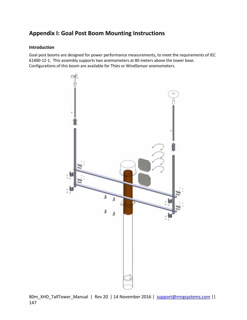
80m_XHD_TallTower_Manual | Rev 20 | 14 November 2016 | [email protected] || 147
Appendix I: Goal Post Boom Mounting Instructions
Introduction
Goal post booms are designed for power performance measurements, to meet the requirements of IEC 61400-12-1. This assembly supports two anemometers at 80 meters above the tower base. Configurations of this boom are available for Thies or WindSensor anemometers.
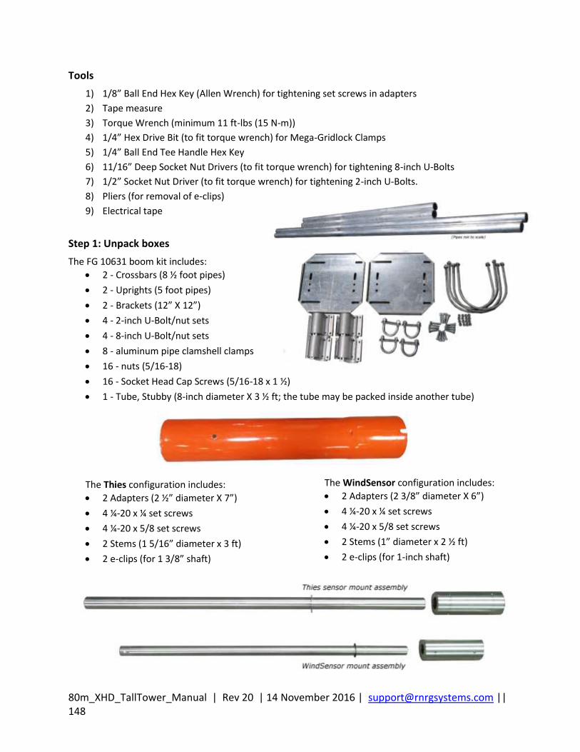
80m_XHD_TallTower_Manual | Rev 20 | 14 November 2016 | [email protected] || 148
Tools
1) 1/8” Ball End Hex Key (Allen Wrench) for tightening set screws in adapters
2) Tape measure
3) Torque Wrench (minimum 11 ft-lbs (15 N-m))
4) 1/4” Hex Drive Bit (to fit torque wrench) for Mega-Gridlock Clamps
5) 1/4” Ball End Tee Handle Hex Key
6) 11/16” Deep Socket Nut Drivers (to fit torque wrench) for tightening 8-inch U-Bolts
7) 1/2” Socket Nut Driver (to fit torque wrench) for tightening 2-inch U-Bolts.
8) Pliers (for removal of e-clips)
9) Electrical tape
Step 1: Unpack boxes
The FG 10631 boom kit includes:
2 - Crossbars (8 ½ foot pipes)
2 - Uprights (5 foot pipes)
2 - Brackets (12” X 12”)
4 - 2-inch U-Bolt/nut sets
4 - 8-inch U-Bolt/nut sets
8 - aluminum pipe clamshell clamps
16 - nuts (5/16-18)
16 - Socket Head Cap Screws (5/16-18 x 1 ½)
1 - Tube, Stubby (8-inch diameter X 3 ½ ft; the tube may be packed inside another tube)
The Thies configuration includes:
2 Adapters (2 ½” diameter X 7”)
4 ¼-20 x ¼ set screws
4 ¼-20 x 5/8 set screws
2 Stems (1 5/16” diameter x 3 ft)
2 e-clips (for 1 3/8” shaft)
The WindSensor configuration includes:
2 Adapters (2 3/8” diameter X 6”)
4 ¼-20 x ¼ set screws
4 ¼-20 x 5/8 set screws
2 Stems (1” diameter x 2 ½ ft)
2 e-clips (for 1-inch shaft)
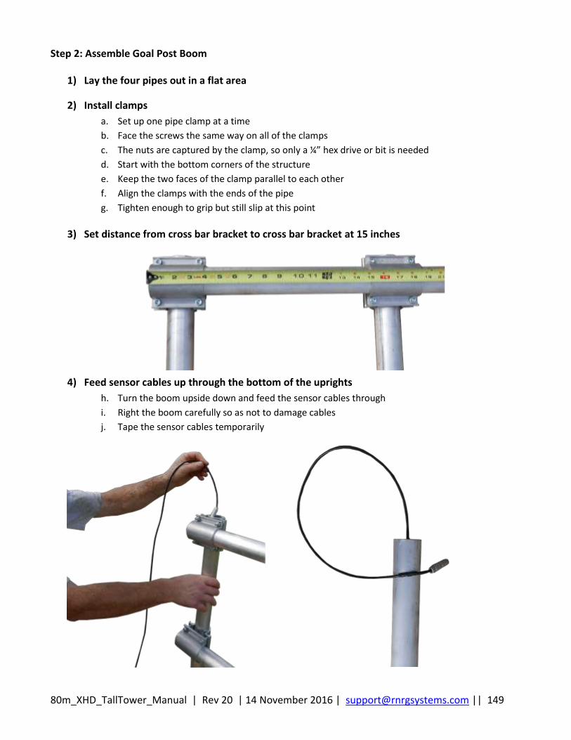
80m_XHD_TallTower_Manual | Rev 20 | 14 November 2016 | [email protected] || 149
Step 2: Assemble Goal Post Boom
1) Lay the four pipes out in a flat area
2) Install clamps
a. Set up one pipe clamp at a time
b. Face the screws the same way on all of the clamps
c. The nuts are captured by the clamp, so only a ¼” hex drive or bit is needed
d. Start with the bottom corners of the structure
e. Keep the two faces of the clamp parallel to each other
f. Align the clamps with the ends of the pipe
g. Tighten enough to grip but still slip at this point
3) Set distance from cross bar bracket to cross bar bracket at 15 inches
4) Feed sensor cables up through the bottom of the uprights
h. Turn the boom upside down and feed the sensor cables through
i. Right the boom carefully so as not to damage cables
j. Tape the sensor cables temporarily
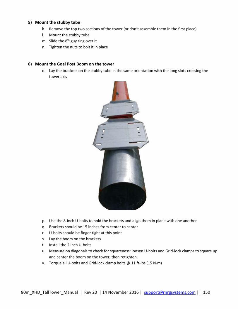
80m_XHD_TallTower_Manual | Rev 20 | 14 November 2016 | [email protected] || 150
5) Mount the stubby tube
k. Remove the top two sections of the tower (or don’t assemble them in the first place)
l. Mount the stubby tube
m. Slide the 8th guy ring over it
n. Tighten the nuts to bolt it in place
6) Mount the Goal Post Boom on the tower
o. Lay the brackets on the stubby tube in the same orientation with the long slots crossing the
tower axis
p. Use the 8-Inch U-bolts to hold the brackets and align them in plane with one another
q. Brackets should be 15 inches from center to center
r. U-bolts should be finger tight at this point
s. Lay the boom on the brackets
t. Install the 2 inch U-bolts
u. Measure on diagonals to check for squareness; loosen U-bolts and Grid-lock clamps to square up
and center the boom on the tower, then retighten.
v. Torque all U-bolts and Grid-lock clamp bolts @ 11 ft-lbs (15 N-m)
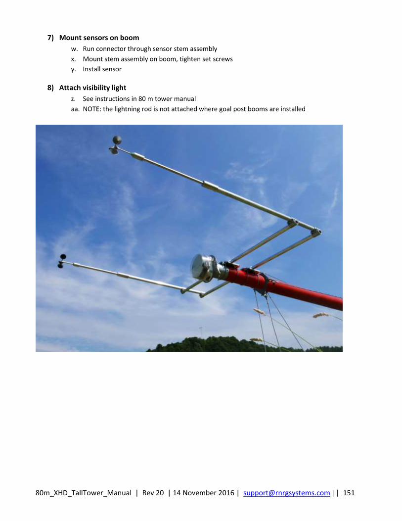
80m_XHD_TallTower_Manual | Rev 20 | 14 November 2016 | [email protected] || 151
7) Mount sensors on boom
w. Run connector through sensor stem assembly
x. Mount stem assembly on boom, tighten set screws
y. Install sensor
8) Attach visibility light
z. See instructions in 80 m tower manual
aa. NOTE: the lightning rod is not attached where goal post booms are installed

80m_XHD_TallTower_Manual | Rev 20 | 14 November 2016 | [email protected] || 152
Index 40 m .......................................................................... 15 40 m HD .................................................................... 15 50 m .......................................................................... 15 50 m HD .................................................................... 15 60 m .......................................................................... 15 60m XHD TallTower Painted Version ..................... 124 anchor placement ............................................. 28, 120 anchor radii ............................................................... 25 anchor requirements .............................................. 117 anchoring ......... 14, 25, 28, 95, 117, 119, 120, 122, 123 Anchoring Guidelines ............................................. 117 anchoring in solid rock............................................ 119 anchoring the baseplate ..................................... 35, 36 anchors ............................ 25, 28, 37, 98, 117, 118, 120 Anchors ..................................................................... 23 base plate ..................................................... 14, 17, 28 base tube .................................................................. 40 baseplate . 14, 25, 28, 30, 31, 33, 35, 38, 40, 46, 54, 87 batteries ................................................................. 123 boom, mounting ..................................................... 137 cement grout .......................................................... 122 doublers .................................................................... 34 electrical tape ........................................................... 47 Envirocrate ........................................17, 18, 19, 21, 22 gin pole assembly ..................................................... 54 Ginpole Tilt-Up ......................................................... 82 ground wire .............................................................. 48 gussets ................................................................ 33, 35 guy guards ................................................................ 98 guy ring corners ........................................................ 46 guy rings ................................................. 38, 46, 50, 82 guy wire tensioning .................................................. 83 guy wires ................................................................... 49 guys ............................................... 25, 89, 98, 120, 122 helper ginpole ....................................... 54, 68, 76, 102 icing .......................................................... 98, 117, 123 installing rock anchors .................................... 120, 122
lance……………………………………………………………………44 lifter transfer hoist .................................................. 102 lifter wires ................................................................. 50 lifters ....................................................... 49, 65, 82, 86 lightning spike ........................................................... 46 Painted 60 m XHD ................................................... 124 pivot pipe ............................................................ 40, 54 quick release pin ....................................................... 40 rock anchors ........................................................... 119 rock anchors, installing ................................... 120, 122 safety cable ............................................................... 55 screw-in anchors, installing .................................... 119 sensor cables ............................................................ 48 settling ...................................................................... 98 shackles ..................................................................... 82 Side mount booms .................................................. 137 Site Layout ................................................................ 23 site visit procedures ................................................ 123 slack in guy wires .................................... 120, 122, 123 soil ........................................................... 117, 118, 120 soil type........................................................... 117, 146 snap through……………………………………………………….99 straightening the tower ............................................ 88 stretch, guy wires ..................................................... 98 TallTower installation on a slope .............................. 25 tension, guy wire .......................................... 28, 84, 89 tools .......................................................................... 16 Tower Lowering ...................................................... 101 Tower Tilt-Up ............................................................ 83 transferring the lifting guys ...................................... 95 transition tube .......................................................... 38 tube layout ................................................................ 38 unpacking ............................................................ 13, 18 winch14, 15, 25, 28, 35, 70, 74, 75, 76, 86, 87, 102, 105 wind vane alignment .............................................. 142 wire rope clips .............................................. 53, 84, 98