rnd0056 pneumatic filter shutter user manual media/alme-ends-019... · if the equipment is used in...
TRANSCRIPT
© FMB Oxford Ltd 2018 Commercial in Confidence Page 1 of 21
Revision 1.0
Pneumatic Filter Shutter
User Manual
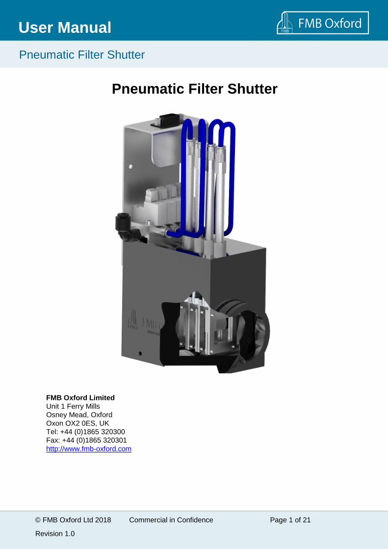
Pneumatic Filter Shutter
FMB Oxford LimitedUnit 1 Ferry MillsOsney Mead, OxfordOxon OX2 0ES, UKTel: +44 (0)1865 320300Fax: +44 (0)1865 320301http://www.fmb-oxford.com

© FMB Oxford Ltd 2018 Commercial in Confidence Page 2 of 21
Revision 1.0
Pneumatic Filter Shutter
User Manual
IMPORTANT INFORMATIONThis manual details the specification and operating requirements for the Pneumatic Filter Shuttersupplied by FMB Oxford.
Before attempting to operate the system, PLEASE READ THIS MANUAL.
This product should only be used by persons legally permitted to do so.
WarrantyProducts of FMB Oxford are warranted to be free from all defects in materials and workmanship.The liability of FMB Oxford under this guarantee is limited to servicing, adjusting or replacingdefective parts. The guarantee is effective 12 months from the date of acceptance, provided:
1. The product is returned to the factory and undamaged by failure to provide sufficient packaging.
2. The product appears to FMB Oxford's satisfaction to be defective through no fault of the user.
3. The equipment has been handled and operated in accordance with the instructions and advicegiven in this manual or any other instructions which have been provided by FMB Oxford.
4. If you have any Customer Service Issues, contact us on either phone: +44 1865 320300 or Email:[email protected] or your Project Leader.
5. When returning components for service or repair, it is essential that the item is shipped togetherwith a signed Customer Returns Authorisation Form.
Feedback
Care has been taken to ensure the information in this manual is accurate and at an appropriatelevel. Please inform FMB Oxford if you have any suggestions for corrections or improvements tothis manual.
© FMB Oxford Ltd 2018 Commercial in Confidence Page 3 of 21
Revision 1.0
Pneumatic Filter Shutter
User Manual
CONTENTSImportant Information ........................................................................................................ 2
Contents .............................................................................................................................. 3
General Health and Safety Information............................................................................. 4
1 Introduction................................................................................................................... 5Scope ..................................................................................................................................51.1How to Use This Manual ......................................................................................................51.2Scope of Supply...................................................................................................................61.3Documentation, Shipping, Installation, Warranty..................................................................61.4
2 System Overview.......................................................................................................... 7
3 Technical Description .................................................................................................. 8
4 Installation..................................................................................................................... 9Foil Installation.....................................................................................................................94.1
5 PNEUMATIC FILTER SHUTTER Beamline Installation .............................................11Installation Fixtures ............................................................................................................125.1Pneumatic Installation........................................................................................................135.2
6 Operation......................................................................................................................14Modes of Operation ...........................................................................................................146.1
7 Maintenance Instructions ...........................................................................................15
8 Replacement Parts ......................................................................................................16
9 Mechanical Drawings ..................................................................................................17
10 Electrical Drawings...................................................................................................18
Appendix 1: Health and Safety...........................................................................................19Safe Mechanical Practice ............................................................................................................19X-rays..........................................................................................................................................19Modifications and service ............................................................................................................19
Appendix 2: Specifications...............................................................................................20Environment ................................................................................................................................20Vacuum System ..........................................................................................................................20Mechanical Data..........................................................................................................................20Pneumatic Data...........................................................................................................................20Functional Data ...........................................................................................................................21Foil Holder actuator .....................................................................................................................21

© FMB Oxford Ltd 2018 Commercial in Confidence Page 4 of 21
Revision 1.0
Pneumatic Filter Shutter
User Manual
GENERAL HEALTH AND SAFETYINFORMATIONIn normal operation, the system is designed to operate safely. The user should, however, beaware of potential hazards which exist in and around equipment of this type and of the ways ofavoiding possible injury and equipment damage which may result from inappropriate ways ofworking. A description of such potential hazards and how to avoid them is given in Appendix 1.
If the equipment is used in a manner not specified in the User Manual, the protection provided bythe equipment may be impaired.
Cautions will be highlighted throughout the manual to avoid equipment damage. This manualadopts the following convention:
WARNINGIndicates a potential hazard which may result in injury or death
CAUTIONIndicates a potential hazard which may result in damage to equipment
See original manufacturers' manuals for further safety data on third party equipment supplied withthe system.
© FMB Oxford Ltd 2018 Commercial in Confidence Page 5 of 21
Revision 1.0
Pneumatic Filter Shutter
User Manual
1 INTRODUCTIONScope1.1
This manual applies to the Pneumatic Filter Shutter supplied by FMB Oxford.
How to Use This Manual1.2
All personnel who are likely to operate the system or come into contact with any of the systemcomponents should read the Health and Safety Information section of the manual (Appendix 1).This provides basic information aimed at highlighting the safety hazards associated with theequipment.
The purpose of this manual is to:
Explain the purpose of the equipment
Explain how to operate the equipment
List some performance characteristics of the equipment
Assist with simple maintenance
More detailed information and instructions for component parts of the system are given in the 3rd
party manuals supplied with the system, which are listed in appendix 2.

© FMB Oxford Ltd 2018 Commercial in Confidence Page 6 of 21
Revision 1.0
Pneumatic Filter Shutter
User Manual
Scope of Supply1.3
Note: A 24V power supply and air supply are also required for operation.
Part Number Description Image
AAM0129 Pneumatic Filter ShutterAssembly
Documentation, Shipping, Installation, Warranty1.4
Customer documentation: user manual.
Packing and shipping.
12 months warranty.
© FMB Oxford Ltd 2018 Commercial in Confidence Page 7 of 21
Revision 1.0
Pneumatic Filter Shutter
User Manual
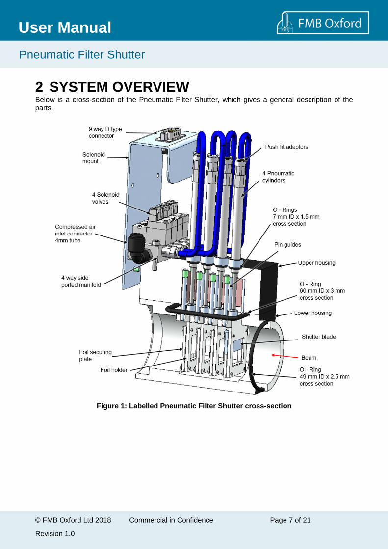
2 SYSTEM OVERVIEWBelow is a cross-section of the Pneumatic Filter Shutter, which gives a general description of theparts.
Figure 1: Labelled Pneumatic Filter Shutter cross-section

© FMB Oxford Ltd 2018 Commercial in Confidence Page 8 of 21
Revision 1.0
Pneumatic Filter Shutter
User Manual
3 TECHNICAL DESCRIPTIONThe Pneumatic Filter Shutter is an in-line device which will attenuate an x-ray beam upon theinsertion of up to four filter foils. The filter foils are held between two plates on their own carrierwhich can be remotely moved in and out of beam by pneumatic cylinders, controlled by electricallyactuated solenoid valves.
1 or two shutter blades can be attached to the foil carriers in order to control the size of the beam inthe vertical direction or to block the beam. This can be used to minimise damage to radiationsensitive samples.
The filter foil size used should be 25 mm x 25 mm square and up to 3mm thick.
© FMB Oxford Ltd 2018 Commercial in Confidence Page 9 of 21
Revision 1.0
Pneumatic Filter Shutter
User Manual
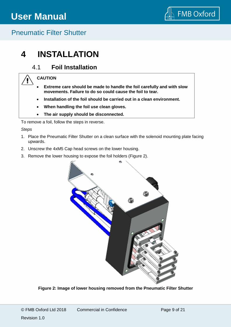
4 INSTALLATION
Foil Installation4.1
CAUTION
Extreme care should be made to handle the foil carefully and with slowmovements. Failure to do so could cause the foil to tear.
Installation of the foil should be carried out in a clean environment.
When handling the foil use clean gloves.
The air supply should be disconnected.
To remove a foil, follow the steps in reverse.
Steps
1. Place the Pneumatic Filter Shutter on a clean surface with the solenoid mounting plate facingupwards.
2. Unscrew the 4xM5 Cap head screws on the lower housing.
3. Remove the lower housing to expose the foil holders (Figure 2).
Figure 2: Image of lower housing removed from the Pneumatic Filter Shutter

© FMB Oxford Ltd 2018 Commercial in Confidence Page 10 of 21
Revision 1.0
Pneumatic Filter Shutter
User Manual
4. Wearing clean, lint-free, gloves and using a clean screw driver loosen the filter holder nut onthe chosen filter holder assembly so that it comes free from the pneumatic cylinder (Figure3).
5. Unscrew the 4 x M2 Cap head screws and remove the foil securing plate (Figure 3).
Figure 3: Exploded view of foil holder assembly
6. In a clean, draft free laboratory gently remove the foil from its container. It is essential that therebe no excessive air movement. Gripping the edge of the foil (within 2 mm) with small wafertweezers is a recommended way of handling the foil. Always move a foil such that it travelsedgeways to the air, as even the slightest draft (such as a breath) against the face of the foilmay break it.
7. Carefully place the foil into the foil holder. Ensure that it is the right way around.
8. Reattach the securing plate and the filter holder assembly to the pneumatic cylinder.
9. Close the Pneumatic Filter Shutter and tighten the screws. Note: The Pneumatic Filter Shutteronly closes one way.

© FMB Oxford Ltd 2018 Commercial in Confidence Page 11 of 21
Revision 1.0
Pneumatic Filter Shutter
User Manual
5 PNEUMATIC FILTER SHUTTER BEAMLINEINSTALLATION
CAUTION
When attaching the Pneumatic Filter Shutter to the beamline be aware thatshock vibration could cause the foil to tear.
The air supply for the Pneumatic Filter Shutter needs to be at 3 bar and supplied via 4 mm tube; seeFigure 4 for reference.
Figure 4: Beam direction
© FMB Oxford Ltd 2018 Commercial in Confidence Page 12 of 21
Revision 1.0
Pneumatic Filter Shutter
User Manual
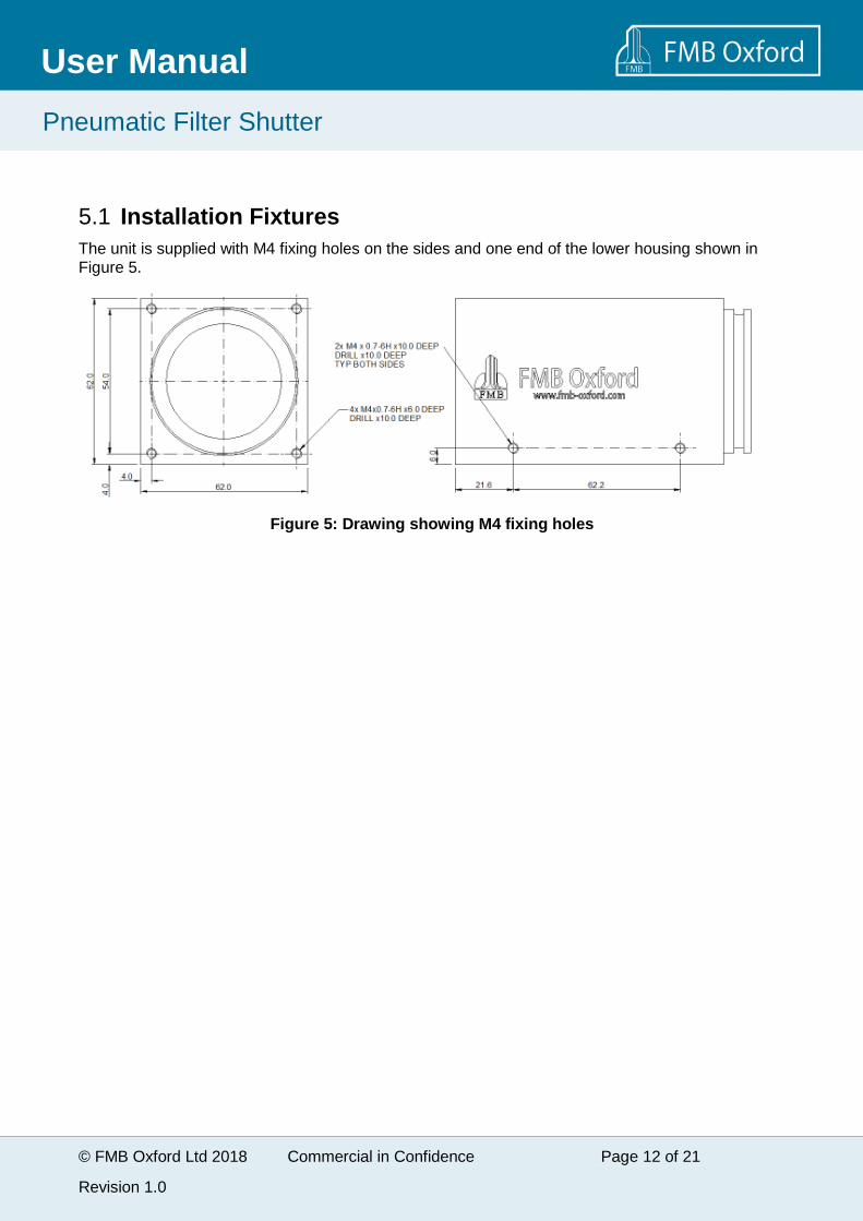
Installation Fixtures5.1
The unit is supplied with M4 fixing holes on the sides and one end of the lower housing shown inFigure 5.
Figure 5: Drawing showing M4 fixing holes
© FMB Oxford Ltd 2018 Commercial in Confidence Page 13 of 21
Revision 1.0
Pneumatic Filter Shutter
User Manual
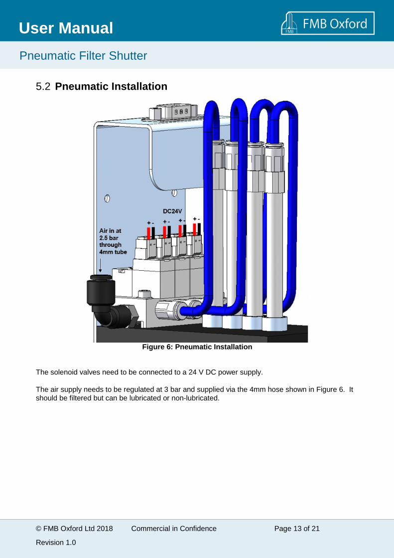
Pneumatic Installation5.2
Figure 6: Pneumatic Installation
The solenoid valves need to be connected to a 24 V DC power supply.
The air supply needs to be regulated at 3 bar and supplied via the 4mm hose shown in Figure 6. Itshould be filtered but can be lubricated or non-lubricated.
© FMB Oxford Ltd 2018 Commercial in Confidence Page 14 of 21
Revision 1.0
Pneumatic Filter Shutter
User Manual
6 OPERATIONThe foils have two positions; in and out of beam. To extend a foil in to the beam open theassociated solenoid valve. The rest position of the foils is out of beam.
CAUTION
Always raise the foil to the out of beam position before the unit is evacuatedor vented to atmosphere. Failure to protect the foil during these operationsmay result in damage.
Modes of Operation6.1
A combination of up to four foils and up to two shutter blades can be used on the four foil holders togain different attenuations of the x-ray.
© FMB Oxford Ltd 2018 Commercial in Confidence Page 15 of 21
Revision 1.0
Pneumatic Filter Shutter
User Manual
7 MAINTENANCE INSTRUCTIONSBefore maintenance commences on this equipment it is important that you familiarise yourself withthe health and safety documentation provided in Appendix 1. Additionally, ensure you are aware ofand understand the specific health and safety guidelines provided by the facility you are working at.
CAUTIONS
1. When performing maintenance or other procedures, ensure that nothingcontaminates or damages the surfaces of the foils. Dirt or other particleson the surface of the foil can cause deterioration in the performance ofthe Pneumatic Filter Shutter. If the foil surfaces do become contaminatedor damaged, contact FMB Oxford for further advice. Do not attempt toremove the contamination.
2. Avoid contamination of vacuum surfaces. Make sure normal vacuumcomponent handling procedures are observed.
3. Only open and handle the Pneumatic Filter Shutter in a clean area.
4. Use clean, lint-free, gloves if any vacuum surfaces have to be handled.
5. Use only clean tools in contact with vacuum surfaces.
6. Minimise exposure to atmospheric air, as water will adsorb on exposedsurfaces and extend pumping times. Store vacuum equipment undervacuum or dry nitrogen.
© FMB Oxford Ltd 2018 Commercial in Confidence Page 16 of 21
Revision 1.0
Pneumatic Filter Shutter
User Manual
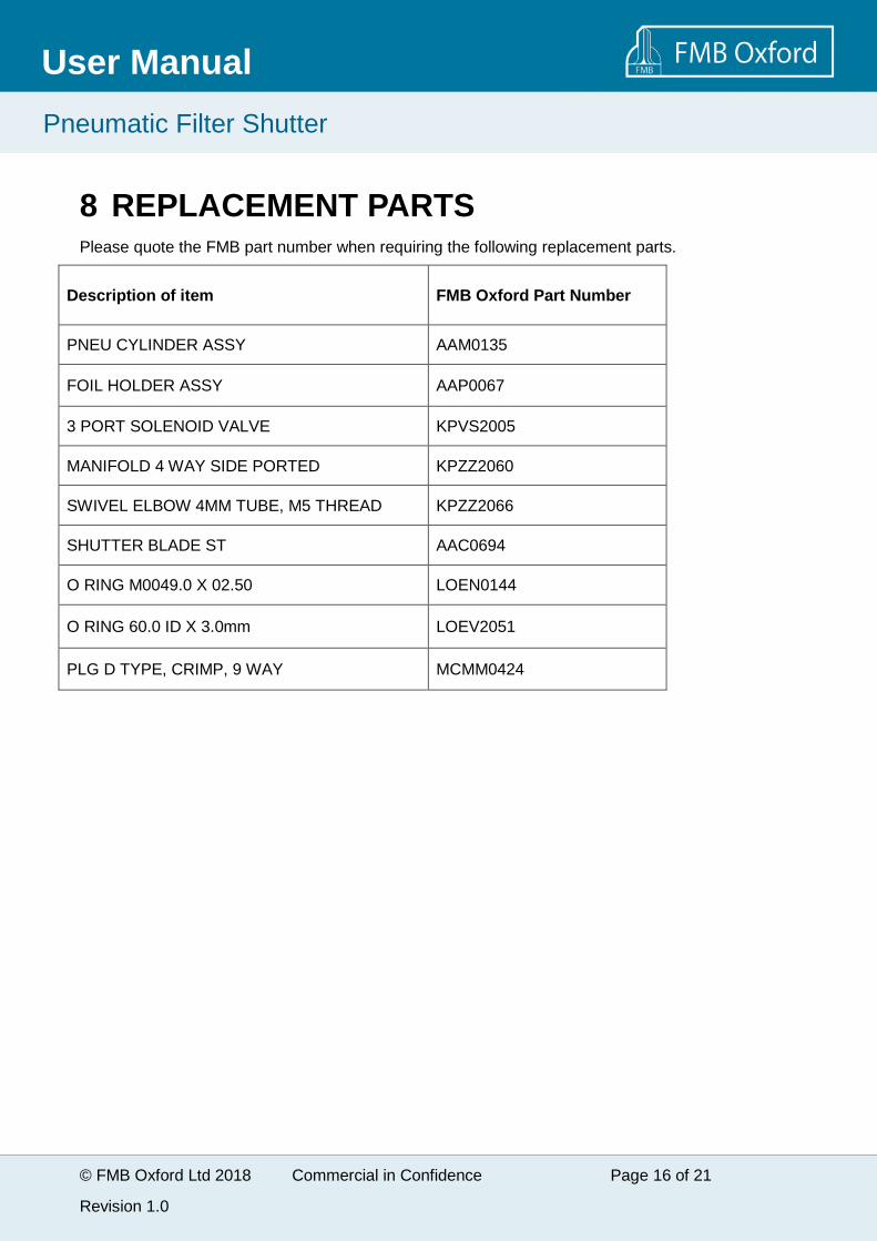
8 REPLACEMENT PARTSPlease quote the FMB part number when requiring the following replacement parts.
Description of item FMB Oxford Part Number
PNEU CYLINDER ASSY AAM0135
FOIL HOLDER ASSY AAP0067
3 PORT SOLENOID VALVE KPVS2005
MANIFOLD 4 WAY SIDE PORTED KPZZ2060
SWIVEL ELBOW 4MM TUBE, M5 THREAD KPZZ2066
SHUTTER BLADE ST AAC0694
O RING M0049.0 X 02.50 LOEN0144
O RING 60.0 ID X 3.0mm LOEV2051
PLG D TYPE, CRIMP, 9 WAY MCMM0424
© FMB Oxford Ltd 2018 Commercial in Confidence Page 17 of 21
Revision 1.0
Pneumatic Filter Shutter
User Manual
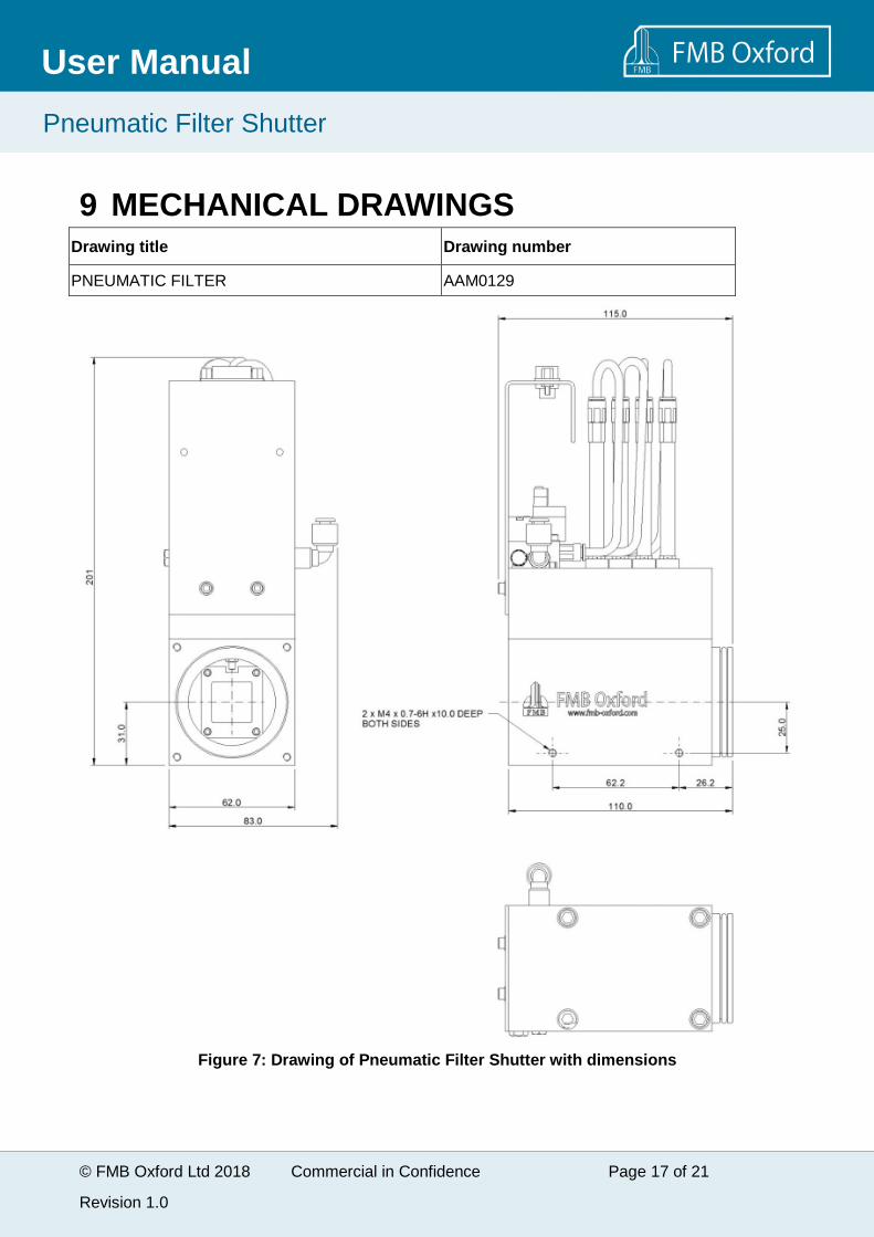
9 MECHANICAL DRAWINGSDrawing title Drawing number
PNEUMATIC FILTER AAM0129
Figure 7: Drawing of Pneumatic Filter Shutter with dimensions
© FMB Oxford Ltd 2018 Commercial in Confidence Page 18 of 21
Revision 1.0
Pneumatic Filter Shutter
User Manual
10 ELECTRICAL DRAWINGS
Drawing title Drawing number
PNEUMATIC 4 FILTER WIRING CQP1020
© FMB Oxford Ltd 2018 Commercial in Confidence Page 19 of 21
Revision 1.0
Pneumatic Filter Shutter
User Manual
APPENDIX 1: HEALTH AND SAFETY
WARNINGDo not take risks. You have a responsibility to ensure the safecondition and safe operation of equipment.
Safe Mechanical Practice
In normal use personnel are not required to undertake mechanical work. Servicing or repair may,however, necessitate access to any part of the system. Only suitably qualified and trainedpersonnel should attempt to dismantle, modify or repair equipment.
X-rays
WARNING
This equipment is intended for use on an x-ray beamline of asynchrotron. Ensure that safe working practices relating to radiationare employed. Follow any local, national or international rules andguidelines.
The manufacturer will not be held responsible for the safety of personnel injured by ionizingradiation as a result of inadequacy of the customer's own radiation protection system.
Modifications and service
The safety, reliability or performance of the equipment may be impaired if assembly operations,extensions, re-adjustments, modifications or repairs are not carried out in accordance with theinstructions provided in this manual and with any other instructions issued by the manufacturer. Ifyou wish to modify the equipment please contact FMB Oxford for further advice.
It should be stressed that those parts of the equipment which are interchangeable, and which aresubject to deterioration during operation, may significantly affect the safety of the equipment.

© FMB Oxford Ltd 2018 Commercial in Confidence Page 20 of 21
Revision 1.0
Pneumatic Filter Shutter
User Manual
APPENDIX 2: SPECIFICATIONS
Environment
Ambient temperature 0C to 35C
Storage temperature 0C to 40C
Relative humidity 10 – 95% non – condensing
Vacuum System
Vacuum HV compatible (<5x10⁻⁷ mbar)
Helium leak rate < 2 x 10 -8 mbar l/sec
Mechanical Data
Approximate mass of unit 1.3 kg
Electrical Data
Connector TypeSubminiature 9 pin male D plug. Mates to 9pin female D receptacle.
Pneumatic Data
Cylinder type SMC Pneumatic Cylinder CJ2B6-25SRZ
Pressure Range 0.6 to 7 bar (flow-control optimised at 3bar)
Operating Temperature 0°C to 70°C
Stroke length 25mm
Solenoid valve SMC 3 Port Direct Operated Valve SY114-5L-Q
Pressure Range 0 bar to 7 bar
Operating Temperature 5°C to 50°C
Current 35 mA
Voltage DC24V (0.8W)

© FMB Oxford Ltd 2018 Commercial in Confidence Page 21 of 21
Revision 1.0
Pneumatic Filter Shutter
User Manual
Functional Data
Maximum Beam Aperture 20 mm (H) x 20 (V) mm
Dimensions 110L X 62W X 200H
Flange type BPC
Foil Holder actuator
Vertical range 25 mm