rms power detector 75 db, dc - 3.9 ghz - · pdf fileorder on-line at power detectors - smt...
TRANSCRIPT

For price, delivery, and to place orders, please contact Hittite Microwave Corporation:20 Alpha Road, Chelmsford, MA 01824 Phone: 978-250-3343 Fax: 978-250-3373
Order On-line at www.hittite.com
PO
WE
R D
ET
EC
TO
RS
- S
MT
12
12 - 26
HMC610LP4 / 610LP4E
General Description
Features
Functional Diagram
The HMC610LP4E Power Detector is designed for RF power measurement, and control applications for frequencies up to 3.9 GHz. The detector provides a “true RMS” representation of any RF/IF input signal. The output is a temperature compensated monotonic, representation of real signal power, measured with a differential input sensing range of 75 dB, or 72 dB of single-ended sensing range.
The HMC610LP4E is ideally suited to those wide bandwidth, wide dynamic range applications, requir-ing repeatable measurement of real signal power, especially where RF/IF wave shape and/or crest factor change with time.
±1 dB Detection Accuracy to 3.9 GHz
Input Dynamic Range: -60 dBm to +15 dBm
RF Signal Wave shape & Crest Factor Independent
Operates with Single-Ended or Differential Input
+5V Operation from -40°C to +85°C
Excellent Temperature Stability
Power-Down Mode
24 Lead 4x4mm SMT Package: 16mm2
Typical Applications
The HMC610LP4(E) is ideal for:
• Log –> Root-Mean-Square (RMS) Conversion
• Received Signal Strength Indication (RSSI)
• Transmitter Signal Strength Indication (TSSI)
• RF Power Amplifi er Efficiency Control
• Receiver Automatic Gain Control
• Transmitter Power Control
Electrical Specifi cations, TA = +25C, Vcc= 5V
RMS POWER DETECTOR
75 dB, DC - 3.9 GHz
v12.0309
Parameter Typ. Typ. Typ. Typ. Typ. Typ. Typ. Units
Dynamic Range (± 1 dB measurement error)
Input Frequency < 900 1900 2200 2700 3000 3500 3900 MHz
Differential Input Confi guration [1] > 75 70 67 66 67 56 48 dB
Input Signal Frequency < 900 1300 ± 300 2300 ± 300 3300 ± 300 MHz
Single-Ended Input Confi guration 66 [2] 72 [3] 69 [3] 65 [3] dB
Deviation vs. Temperature:
Deviation is measure from reference, which is the same CW input at 25 °C
[1] Differential Input Interface with 1:1 Balun Transformer (over full input frequency range) ± 0.6 dB
[2] Wideband Single-Ended Input Interface suitable for input signal frequencies below 1000 MHz
± 0.3 dB
[3] Tuned Single-Ended Input Interface suitable for input signal frequencies above 1000 MHz ± 0.5 dB

For price, delivery, and to place orders, please contact Hittite Microwave Corporation:20 Alpha Road, Chelmsford, MA 01824 Phone: 978-250-3343 Fax: 978-250-3373
Order On-line at www.hittite.com
PO
WE
R D
ET
EC
TO
RS
- S
MT
12
12 - 27
HMC610LP4 / 610LP4Ev12.0309
RMS POWER DETECTOR
75 dB, DC - 3.9 GHz
Table 2: Electrical Specifi cations II, HMC610LP4E Evaluation Kit (Diff. Input Confi g.), TA = +25C, Vcc= +5V, CINT = 0.1 μF, Unless Otherwise Noted.Parameter Typ. Typ. Typ. Typ. Typ. Typ. Typ. Units
Input Signal Frequency 900 1900 2200 2700 3000 3500 3900 MHz
Modulation Deviation (Deviation measured from reference, which is measured with CW input at equivalent input signal power)
CDMA2000 3 Carriers, 9 Channels 0.1 0.08 0.1 0.14 0.2 0.25 0.3 dB
CDMA2000 1 Carrier, 9 Channels 0.15 0.12 0.15 0.18 0.25 0.3 0.35 dB
IS95 Reverse Link 0.05 0.05 0.1 0.1 0.1 0.15 0.2 dB
WCDMA 1 Carrier 0.1 0.14 0.12 0.18 0.2 0.3 0.3 dB
WCDMA 4 Carrier 0.2 0.22 0.24 0.24 0.3 0.4 0.4 dB
Differential Input Confi guration Logarithmic Slope and Intercept
Logarithmic Slope 36.5 37.3 37.8 39.3 40.5 43.5 47.5 mV/dB
Logarithmic Intercept -72 -70 -69 -65 -62 -57 -53 dBm
Max. Input Power ar ± 1 dB Error >+15 +10 +7 +10 +12 +8 +4 dBm
Min. Input Power at ± 1 dB Error -60 -60 -60 -56 -52 -48 -44 dBm
Single-Ended Input Confi guration Logarithmic Slope & Intercept
Input Signal Frequency < 900 [2] 1300 ± 300 [3] 2300 ± 300 [3] 3300 ± 300 [3] MHz
Logarithmic Slope 37.3 36.4 37.9 41.9 mV/dB
Logarithmic Intercept -70 -69 -67 -60 dBm
Max. Input Power at ±1.25 dB Error 7 15 13 15 dBm
Min. Input Power at ±1.25 dB Error -59 -57 -56 -50 dBm
[2] Wideband Single-Ended Input Interface suitable for input signal frequencies below 1000 MHz
[3] Tuned Single-Ended Input Interface suitable for input signal frequencies above 1000 MHz
RMSOUT Error vs. Pin with
Different Modulations @ 3000 MHz
RMSOUT vs. Pin with
Different Modulations @ 3000 MHz
-4
-3
-2
-1
0
1
2
3
4
-60 -50 -40 -30 -20 -10 0 10
CWCDMA2000 3 carriers 9 chnCDMA2000 single carrier 9 chnIS95 reverse linkWCDMA 4 carriersWCDMA single carrier
ER
RO
R (
dBm
)
INPUT POWER (dBm)
0
0.5
1
1.5
2
2.5
3
3.5
4
-70 -60 -50 -40 -30 -20 -10 0 10
IdealCWCDMA2000 3 carriers 9 chnCDMA2000 single carrier 9 chnIS95 reverse linkWCDMA 4 carriersWCDMA single carrier
RM
SO
UT
(V
)
INPUT POWER (dBm)

For price, delivery, and to place orders, please contact Hittite Microwave Corporation:20 Alpha Road, Chelmsford, MA 01824 Phone: 978-250-3343 Fax: 978-250-3373
Order On-line at www.hittite.com
PO
WE
R D
ET
EC
TO
RS
- S
MT
12
12 - 28
Parameter Conditions Min. Typ. Max. Units
Differential Input Confi guration
Input Network Return Loss [1] [1] >10 dB
Input Resistance between IN+ and IN- Between pins 3 and 4 200 Ω
Input Voltage Range VDIFFIN = VIN+ - VIN- 2.25 V
Single-Ended Input Confi guration
Input Network Return Loss [2] [2], [3] >10 dB
Input Voltage Range VSEin = VIN+ 1.4 V
RMSOUT Output
Output Voltage Range RL - 1kΩ, CL = 4.7pF 3.2 V
Source/Sink Current Compliance RMSOUT held at VCC/2 8 / -0.4 mA
Max. Load Capacitance With CINT = 0 35 pF
Output Slew Rate (rise / fall) With CINT = 0, Cofs = 0 15 (200) 106 V/s
VSET Input (Negative Feedback Terminal)
Input Voltage Range 3.2 V
Input Resistance 54 kΩ
VREF Output (Reference Voltage)
VREF Output Voltage 2.0 V
VREF Error Over Full Temperature Range ± 50 mV
VTGT Input (RMS Target Interface)
Input Voltage Range 3.65 V
Input Resistance >1 MΩ
ENX Logic Input (Power Down Control)
Input High Voltage Standby Mode Active 3.9 V
Input Low Voltage Normal Operation 1.2 V
Input High Current 1 μA
Input Low Current 1 μA
Input Capacitance 0.5 pF
Power Supply
Supply Voltage 4.5 5 5.5 V
Supply Current with Pin = -70 dBm Over Full Temperature Range 65 96 mA
Supply Current with Pin = 0 dBm Over Full Temperature Range 79 118 mA
Standby Mode Supply Current ENX = Hi 0.5 mA
[1] Performance of differential input confi guration is limited by balun. Balun used is MACOM ETC1-1-13 good over 4.5 MHz to 3000 MHz[2] Using Wideband Single-Ended Input Interface suitable for input signal frequencies below 1000 MHz[3] Using Tuned Single-Ended Input Interface suitable for input signal frequencies above 1000 MHz
Table 3: Electrical Specifi cations III, HMC610LP4E Evaluation Kit (Diff. Input Confi g.), TA = +25C, Vcc= +5V, CINT = 0.1 μF, Unless Otherwise Noted.
HMC610LP4 / 610LP4Ev12.0309
RMS POWER DETECTOR
75 dB, DC - 3.9 GHz

For price, delivery, and to place orders, please contact Hittite Microwave Corporation:20 Alpha Road, Chelmsford, MA 01824 Phone: 978-250-3343 Fax: 978-250-3373
Order On-line at www.hittite.com
PO
WE
R D
ET
EC
TO
RS
- S
MT
12
12 - 29
[1] CW input waveform, into differential input interface with 1:1 Balun
0
1
2
3
4
-4
-2
0
2
4
-70 -60 -50 -40 -30 -20 -10 0 10
IDEALRMSOUT +25CRMSOUT +85CRMSOUT -40C
ERR +25CERR +85CERR -40C
RM
SO
UT
(V
)
ER
RO
R (dB
)
INPUT POWER (dBm)
RMSOUT & Error vs. Pin @ 900 MHz [1] RMSOUT & Error vs. Pin @ 1900 MHz [1]
0
1
2
3
4
-4
-2
0
2
4
-70 -60 -50 -40 -30 -20 -10 0 10
IDEALRMSOUT +25CRMSOUT +85CRMSOUT -40C
ERR +25CERR +85CERR -40C
RM
SO
UT
(V
)
ER
RO
R (dB
)
INPUT POWER (dBm)
0
1
2
3
4
-4
-2
0
2
4
-70 -60 -50 -40 -30 -20 -10 0 10
IDEALRMSOUT +25CRMSOUT +85CRMSOUT -40C
ERR +25CERR +85CERR -40C
RM
SO
UT
(V)
ER
RO
R (dB
)
INPUT POWER (dBm)
0
1
2
3
4
-4
-2
0
2
4
-60 -50 -40 -30 -20 -10 0 10
IDEALRMSOUT +25CRMSOUT +85CRMSOUT -40C
ERR +25CERR +85CERR -40C
RM
SO
UT
(V)
ER
RO
R (dB
)
INPUT POWER (dBm)
RMSOUT & Error vs. Pin @ 2200 MHz [1] RMSOUT & Error vs. Pin @ 2700 MHz [1]
RMSOUT & Error vs. Pin @ 3000 MHz [1] RMSOUT & Error vs. Pin @ 3500 MHz [1]
0
1
2
3
4
-4
-2
0
2
4
-60 -50 -40 -30 -20 -10 0 10
IDEALRMSOUT +25CRMSOUT +85CRMSOUT -40C
ERR +25CERR +85CERR -40C
RM
SO
UT
(V)
ER
RO
R (dB
)
INPUT POWER (dBm)
0
1
2
3
4
-4
-2
0
2
4
-60 -50 -40 -30 -20 -10 0 10
IDEALRMSOUT +25CRMSOUT +85CRMSOUT -40C
ERR +25CERR +85CERR -40C
RM
SO
UT
(V)
ER
RO
R (dB
)
INPUT POWER (dBm)
HMC610LP4 / 610LP4Ev12.0309
RMS POWER DETECTOR
75 dB, DC - 3.9 GHz
For price, delivery, and to place orders, please contact Hittite Microwave Corporation:20 Alpha Road, Chelmsford, MA 01824 Phone: 978-250-3343 Fax: 978-250-3373
Order On-line at www.hittite.com
PO
WE
R D
ET
EC
TO
RS
- S
MT
12
12 - 30
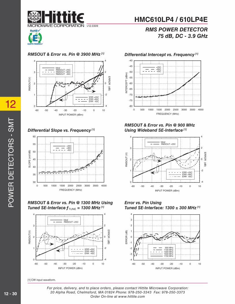
[1] CW input waveform.
RMSOUT & Error vs. Pin @ 3900 MHz [1]
0
1
2
3
4
-4
-2
0
2
4
-60 -50 -40 -30 -20 -10 0 10
IdealRMSOUT +25CRMSOUT +85CRMSOUT -45C
ERR +25CERR +85CERR -45C
RM
SO
UT
(V)
ER
RO
R (dB
)
INPUT POWER (dBm)
Differential Slope vs. Frequency [1]
30
35
40
45
50
55
60
0 500 1000 1500 2000 2500 3000 3500 4000
+25C+85C -45C
SLO
PE
(m
V/d
B)
FREQUENCY (MHz)
Differential Intercept vs. Frequency [1]
RMSOUT & Error vs. Pin @ 900 MHz
Using Wideband SE-Interface [1]
-80
-75
-70
-65
-60
-55
-50
-45
-40
0 500 1000 1500 2000 2500 3000 3500 4000
+25C+85C -45C
INT
ER
CE
PT
(dB
m)
FREQUENCY (MHz)
0
1
2
3
4
-4
-2
0
2
4
-60 -50 -40 -30 -20 -10 0 10
IdealRMSOUT +25C
ERR +25CERR +85CERR -45C
RM
SO
UT
(V
) ER
RO
R (dB
)
INPUT POWER (dBm)
RMSOUT & Error vs. Pin @ 1300 MHz Using
Tuned SE-Interface ƒTUNE = 1300 MHz [1]
0
1
2
3
4
-4
-2
0
2
4
-60 -50 -40 -30 -20 -10 0 10
IdealRMSOUT +25C
ERR +25CERR +85CERR -45C
RM
SO
UT
(V)
ER
RO
R (dB
)
INPUT POWER (dBm)
Error vs. Pin Using
Tuned SE-Interface: 1300 ± 300 MHz [1]
-4
-3
-2
-1
0
1
2
3
4
-60 -50 -40 -30 -20 -10 0 10
900 MHz1100 MHz1300 MHz1500 MHz1700 MHz
ER
RO
R (
dB)
INPUT POWER (dBm)
HMC610LP4 / 610LP4Ev12.0309
RMS POWER DETECTOR
75 dB, DC - 3.9 GHz

For price, delivery, and to place orders, please contact Hittite Microwave Corporation:20 Alpha Road, Chelmsford, MA 01824 Phone: 978-250-3343 Fax: 978-250-3373
Order On-line at www.hittite.com
PO
WE
R D
ET
EC
TO
RS
- S
MT
12
12 - 31
RMSOUT & Error vs. Pin @ 2300 MHz Using
Tuned SE-Interface, ƒTUNE = 2300 MHz [1]
0
1
2
3
4
-4
-2
0
2
4
-70 -60 -50 -40 -30 -20 -10 0 10
IdealRMSOUT+25C
ERR +25CERR +85CERR -45C
RM
SO
UT
(V)
ER
RO
R (dB
)
INPUT POWER (dBm)
Error vs. Pin Using
Tuned SE-Interface: 2300 ± 300 MHz [1]
-4
-3
-2
-1
0
1
2
3
4
-60 -50 -40 -30 -20 -10 0 10
1900 MHz2100 MHz2300 MHz2500 MHz2700 MHz
ER
RO
R (
dB)
INPUT POWER (dBm)
RMSOUT & Error vs. Pin @ 3300 MHz Using
Tuned SE-Interface, ƒTUNE = 3300 MHz [1]
Error vs. Pin Using
Tuned SE-Interface: 3300 ± 300 MHz [1]
-4
-3
-2
-1
0
1
2
3
4
-60 -50 -40 -30 -20 -10 0 10
2900 MHz3100 MHz3300 MHz3500 MHz3700 MHz
ER
RO
R (
dB)
INPUT POWER (dBm)
Error over Supply Voltage &
Temperature Using Tuned SE-Interface
Centered on 1300 MHz [1]
Error over Supply Voltage &
Temperature Using Tuned SE-Interface
Centered on 3300 MHz [1]
-2
-1.5
-1
-0.5
0
0.5
1
1.5
2
-55 -45 -35 -25 -15 -5 5
ER
RO
R (
dB)
INPUT POWER (dBm)
Over Supply Voltage: 4.5V to 5.5Vand over Temperature:-45C to 85C
Deviation over temp and supply voltage extremes
Nominal error at temp = 25C, Vcc = 5V
-2
-1.5
-1
-0.5
0
0.5
1
1.5
2
-55 -45 -35 -25 -15 -5 5
ER
RO
R (
dB)
INPUT POWER (dBm)
Over Supply Voltage: 4.5V to 5.5Vand over Temperature:-45C to 85C
Deviation over temp and supply voltage extremes
Nominal error at temp = 25C, Vcc = 5V
HMC610LP4 / 610LP4Ev12.0309
RMS POWER DETECTOR
75 dB, DC - 3.9 GHz
0
1
2
3
4
-4
-2
0
2
4
-70 -60 -50 -40 -30 -20 -10 0 10
IdealRMSOUT +25C
ERR +25CERR +85CERR -45C
RM
SO
UT
(V)
ER
RO
R (dB
)
INPUT POWER (dBm)
[1] CW input waveform.

For price, delivery, and to place orders, please contact Hittite Microwave Corporation:20 Alpha Road, Chelmsford, MA 01824 Phone: 978-250-3343 Fax: 978-250-3373
Order On-line at www.hittite.com
PO
WE
R D
ET
EC
TO
RS
- S
MT
12
12 - 32
Output Rise-Time to RF Burst [6]
0
0.5
1
1.5
2
2.5
3
3.5
-0.1 0 0.1 0.2 0.3
Cint=0.1uFCint=10nFCint=1nFCint=100pFCint=0
RM
SO
UT
(V
)
TIME (ms)
InputDynamicRange to +/-1dB Error
[6] Input @ 900 MHz, 0 dBm; Vdd = 5V, COFS = 1nF [7] Input @ 900 MHz, CINT = 10nF, COFS = 1nF, Vcc = 5V
Output Fall-Time to RF Burst [6]
0
0.5
1
1.5
2
2.5
3
3.5
-0.5 0.9 2.2 3.6 5
Cint=0.1uFCint=10nFCint=1nFCint=100pFCint=0
RM
SO
UT
(V
)
TIME (ms)
InputDynamicRange to +/-1dB Error
Output Response to RF Burst [7]
-0.5
0
0.5
1
1.5
2
2.5
3
3.5
-0.1 0.1 0.2 0.4 0.5 0.7 0.9 1 1.2 1.3 1.5
-30 dBm-15 dBm 0 dBm
RM
SO
UT
(V
)
TIME (us)
InputDynamicRangeto+/-1dB error
Typical Supply
Current vs. Input Power, Vcc = 5V
Differential Input Return LossUsing Evaluation PCB w/ Differential Input Interface
Single-Ended Input Return LossUsing Evaluation PCB w/Single-Ended Input Interface
-40
-35
-30
-25
-20
-15
-10
-5
0
0 1 2 3 4
S11 Tuned to 1.3 ghzS11 Tuned to 2.3GHzS11 Tuned to 3.3GHzS11 Wideband SE
RE
TU
RN
LO
SS
(dB
)
FREQUENCY (GHz)
-40
-35
-30
-25
-20
-15
-10
-5
0
0 1 2 3 4
RE
TU
RN
LO
SS
(dB
)
FREQUENCY (GHz)
Defined in large part by balun:
4.5MHz to 3000MHz
M/A-Com balun#ETC1-1-113;
60
70
80
90
100
110
120
130
-70 -60 -50 -40 -30 -20 -10 0 10
TYPICALMAXIMUM
SU
PP
LY C
UR
RE
NT
(m
A)
INPUT POWER (dBm)
HMC610LP4 / 610LP4Ev12.0309
RMS POWER DETECTOR
75 dB, DC - 3.9 GHz

For price, delivery, and to place orders, please contact Hittite Microwave Corporation:20 Alpha Road, Chelmsford, MA 01824 Phone: 978-250-3343 Fax: 978-250-3373
Order On-line at www.hittite.com
PO
WE
R D
ET
EC
TO
RS
- S
MT
12
12 - 33
Outline Drawing
NOTES:
1. LEADFRAME MATERIAL: COPPER ALLOY
2. DIMENSIONS ARE IN INCHES [MILLIMETERS].
3. LEAD SPACING TOLERANCE IS NON-CUMULATIVE
4. PAD BURR LENGTH SHALL BE 0.15mm MAXIMUM.
PAD BURR HEIGHT SHALL BE 0.05mm MAXIMUM.
5. PACKAGE WARP SHALL NOT EXCEED 0.05mm.
6. ALL GROUND LEADS AND GROUND PADDLE MUST
BE SOLDERED TO PCB RF GROUND.
7. REFER TO HMC APPLICATION NOTE FOR SUGGESTED PCB LAND PATTERN.
Package Information
Absolute Maximum Ratings
Supply Voltage 5.6V
RF Input Power 20 dBm
Max. Input Voltage 2.25 Vrms
Channel / Junction Temperature 125 °C
Continuous Pdiss (T = 85°C)(Derate 22.72 mW/°C above 85°C)
0.91 Watts
Thermal Resistance (Rth)(junction to ground paddle)
44.02 °C/W
Storage Temperature -65 to +150 °C
Operating Temperature -40 to +85 °C
ELECTROSTATIC SENSITIVE DEVICEOBSERVE HANDLING PRECAUTIONS
Part Number Package Body Material Lead Finish MSL Rating Package Marking [3]
HMC610LP4 Low Stress Injection Molded Plastic Sn/Pb Solder MSL1 [1] H610XXXX
HMC610LP4E RoHS-compliant Low Stress Injection Molded Plastic 100% matte Sn MSL1 [2] H610XXXX
[1] Max peak refl ow temperature of 235 °C[2] Max peak refl ow temperature of 260 °C[3] 4-Digit lot number XXXX
HMC610LP4 / 610LP4Ev12.0309
RMS POWER DETECTOR
75 dB, DC - 3.9 GHz
For price, delivery, and to place orders, please contact Hittite Microwave Corporation:20 Alpha Road, Chelmsford, MA 01824 Phone: 978-250-3343 Fax: 978-250-3373
Order On-line at www.hittite.com
PO
WE
R D
ET
EC
TO
RS
- S
MT
12
12 - 34
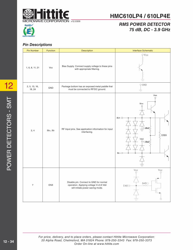
Pin Number Function Description Interface Schematic
1, 6, 8, 11, 21 VccBias Supply. Connect supply voltage to these pins
with appropriate fi ltering.
2, 5, 13, 16, 18, 24
GNDPackage bottom has an exposed metal paddle that
must be connected to RF/DC ground.
3, 4 IN+, IN-RF Input pins. See application information for input
interfacing.
7 ENXDisable pin. Connect to GND for normal operation. Applying voltage V>0.8 Vdd
will initiate power saving mode.
Pin Descriptions
HMC610LP4 / 610LP4Ev12.0309
RMS POWER DETECTOR
75 dB, DC - 3.9 GHz

For price, delivery, and to place orders, please contact Hittite Microwave Corporation:20 Alpha Road, Chelmsford, MA 01824 Phone: 978-250-3343 Fax: 978-250-3373
Order On-line at www.hittite.com
PO
WE
R D
ET
EC
TO
RS
- S
MT
12
12 - 35
Pin Descriptions (Continued)
Pin Number Function Description Interface Schematic
9, 10 COFSInput high pass fi lter capacitor. Connect to common
via a capacitor to determine 3 dB point of input signal high-pass fi lter.
14 VSETVSET input. Short this pin to
RMSOUT for normal operation.
12, 22, 23 N / C These pins are not connected internally.
15 RMSOUTLogarithmic output that converts the input power to a DC level. Short this pin to VSET for normal
operation.
16 IPWR Ground for proper operation
HMC610LP4 / 610LP4Ev12.0309
RMS POWER DETECTOR
75 dB, DC - 3.9 GHz

For price, delivery, and to place orders, please contact Hittite Microwave Corporation:20 Alpha Road, Chelmsford, MA 01824 Phone: 978-250-3343 Fax: 978-250-3373
Order On-line at www.hittite.com
PO
WE
R D
ET
EC
TO
RS
- S
MT
12
12 - 36
Pin Number Function Description Interface Schematic
17 CINTConnection for ground referenced loop fi lter
integration capacitor. See application schematic.
19 VTGTUse of lower target voltage reduces error for
complex signals with large crest factors. Normally connected to VREF.
20 VREF Reference voltage output.
Pin Descriptions (Continued)
HMC610LP4 / 610LP4Ev12.0309
RMS POWER DETECTOR
75 dB, DC - 3.9 GHz
For price, delivery, and to place orders, please contact Hittite Microwave Corporation:20 Alpha Road, Chelmsford, MA 01824 Phone: 978-250-3343 Fax: 978-250-3373
Order On-line at www.hittite.com
PO
WE
R D
ET
EC
TO
RS
- S
MT
12
12 - 37
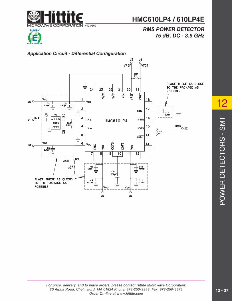
Application Circuit - Differential Confi guration
HMC610LP4 / 610LP4Ev12.0309
RMS POWER DETECTOR
75 dB, DC - 3.9 GHz

For price, delivery, and to place orders, please contact Hittite Microwave Corporation:20 Alpha Road, Chelmsford, MA 01824 Phone: 978-250-3343 Fax: 978-250-3373
Order On-line at www.hittite.com
PO
WE
R D
ET
EC
TO
RS
- S
MT
12
12 - 38
Evaluation PCB - Differential Input Confi guration
The circuit board used in the fi nal application should use RF circuit design techniques. Signal lines should have 50 ohm impedance while the package ground leads and exposed paddle should be con-nected directly to the ground plane similar to that shown. A sufficient number of via holes should be used to connect the top and bottom ground planes. The evaluation circuit board shown is available from Hittite upon request.
List of Materials for Evaluation PCB 118147 [1]
Item Description
J1 - J2 PC Mount SMA connector
J3 - J7 DC Pins
C1 - C3 1 nF Capacitor, 0402 Pkg.
C4, C6, C8, C11, C17 0.1 μF Capacitor, 0402 Pkg.
C5, C9, C12 100 PF Capacitor, 0402 Pkg.
C10 1000 PF Capacitor, 0402 Pkg.
R25 68 Ω Resistor, 0402 Pkg.
R11, R24 0 Ω Resistor, 0402 Pkg.
R4 10k Ω Resistor, 0402 Pkg.
T1 1:1 Balun, M/A-COM ETC1-1-13
U1HMC610LP4 / HMC610LP4ELogarithmic Detector / Controller
PCB [2] 118144 Evaluation PCB
[1] Reference this number when ordering complete evaluation PCB
[2] Circuit Board Material: Arlon 25R
HMC610LP4 / 610LP4Ev12.0309
RMS POWER DETECTOR
75 dB, DC - 3.9 GHz

For price, delivery, and to place orders, please contact Hittite Microwave Corporation:20 Alpha Road, Chelmsford, MA 01824 Phone: 978-250-3343 Fax: 978-250-3373
Order On-line at www.hittite.com
PO
WE
R D
ET
EC
TO
RS
- S
MT
12
12 - 39
HMC610LP4 / 610LP4Ev12.0309
RMS POWER DETECTOR
75 dB, DC - 3.9 GHz
Application Circuit - Single Ended Confi guration

For price, delivery, and to place orders, please contact Hittite Microwave Corporation:20 Alpha Road, Chelmsford, MA 01824 Phone: 978-250-3343 Fax: 978-250-3373
Order On-line at www.hittite.com
PO
WE
R D
ET
EC
TO
RS
- S
MT
12
12 - 40
HMC610LP4 / 610LP4Ev12.0309
RMS POWER DETECTOR
75 dB, DC - 3.9 GHz
Evaluation PCB - Single-Ended
The circuit board used in the fi nal application should use RF circuit design techniques. Signal lines should have 50 ohm impedance while the package ground leads and exposed paddle should be con-nected directly to the ground plane similar to that shown. A sufficient number of via holes should be used to connect the top and bottom ground planes. The evaluation circuit board shown is available from Hittite upon request.
Board is confi gured with wideband single-ended interface suitable for input signal frequencies below 1000 MHz. Refer to section on tuning single-ended interface in application information for operating with signals above 1000 MHz.
List of Materials for Evaluation PCB 119233 [1]
Item Description
J1 - J2 PC Mount SMA connector
J3 - J7 DC Pins
C2 - C3 1 nF Capacitor, 0402 Pkg.
C4, C6, C8, C11, C17 0.1 μF Capacitor, 0402 Pkg.
C5, C9, C12 100 PF Capacitor, 0402 Pkg.
C10 1000 PF Capacitor, 0402 Pkg.
R1 82 Ω Resistor, 0402 Pkg.
R5 27 Ω Resistor, 0402 Pkg.
R2, R11, R24 0 Ω Resistor, 0402 Pkg.
R4 10k Ω Resistor, 0402 Pkg.
U1HMC610LP4 / HMC610LP4ELogarithmic Detector / Controller
PCB [2] 119231 Evaluation PCB
[1] Reference this number when ordering complete evaluation PCB
[2] Circuit Board Material: Arlon 25R
For price, delivery, and to place orders, please contact Hittite Microwave Corporation:20 Alpha Road, Chelmsford, MA 01824 Phone: 978-250-3343 Fax: 978-250-3373
Order On-line at www.hittite.com
PO
WE
R D
ET
EC
TO
RS
- S
MT
12
12 - 41
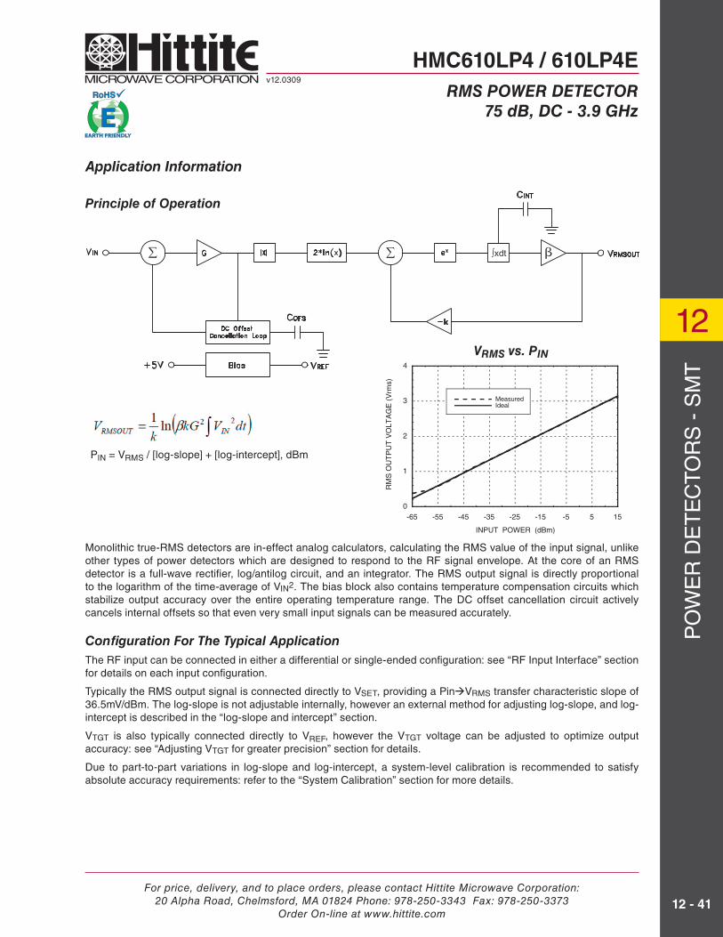
Application Information
PIN = VRMS / [log-slope] + [log-intercept], dBm
Monolithic true-RMS detectors are in-effect analog calculators, calculating the RMS value of the input signal, unlike other types of power detectors which are designed to respond to the RF signal envelope. At the core of an RMS detector is a full-wave rectifi er, log/antilog circuit, and an integrator. The RMS output signal is directly proportional to the logarithm of the time-average of VIN2. The bias block also contains temperature compensation circuits which stabilize output accuracy over the entire operating temperature range. The DC offset cancellation circuit actively cancels internal offsets so that even very small input signals can be measured accurately.
Confi guration For The Typical Application
The RF input can be connected in either a differential or single-ended confi guration: see “RF Input Interface” section for details on each input confi guration.
Typically the RMS output signal is connected directly to VSET, providing a PinVRMS transfer characteristic slope of 36.5mV/dBm. The log-slope is not adjustable internally, however an external method for adjusting log-slope, and log-intercept is described in the “log-slope and intercept” section.
VTGT is also typically connected directly to VREF, however the VTGT voltage can be adjusted to optimize output accuracy: see “Adjusting VTGT for greater precision” section for details.
Due to part-to-part variations in log-slope and log-intercept, a system-level calibration is recommended to satisfy absolute accuracy requirements: refer to the “System Calibration” section for more details.
Principle of Operation
0
1
2
3
4
-65 -55 -45 -35 -25 -15 -5 5 15
MeasuredIdeal
RM
S O
UT
PU
T V
OLT
AG
E (
Vrm
s)
INPUT POWER (dBm)
VRMS vs. PIN
HMC610LP4 / 610LP4Ev12.0309
RMS POWER DETECTOR
75 dB, DC - 3.9 GHz

For price, delivery, and to place orders, please contact Hittite Microwave Corporation:20 Alpha Road, Chelmsford, MA 01824 Phone: 978-250-3343 Fax: 978-250-3373
Order On-line at www.hittite.com
PO
WE
R D
ET
EC
TO
RS
- S
MT
12
12 - 42
RF Input Interface
The IN+ and IN- pins are differential RF inputs, which can be externally confi gured as differential or single-ended input. Power match components are placed at these input terminals, along with DC blocking capacitors. The coupling capacitor values also set the lower spectral boundary of the input signal bandwidth. The inputs can be reactively matched (refer to input return loss graphs), but a resistor network should be sufficient for good wideband performance.
Selecting resistor values for Differential Interface: The value of R25 depends on the balun used; if the balun is 50Ω on both sides of the SE-Diff conversion,
then R25 , Ω , where
RM = the desired power match impedance in ohms
For RM = 50 Ω, R25 = 64.7 Ω ≈ 68 ΩSingle-Ended Input Interface
Tuned SE-interface: for signal frequencies > 900MHz
Choose L and C elements from the following graph for narrowband tuning of the SE-interface: R5 = 27Ω, R1 = 82Ω, C2 = 100 pF, R2 = 0Ω, L1, C3 - see graph.
Wideband SE-interface: for signal frequencies < 900MHz
R5 = 27Ω, R1 = 82Ω,
C2, C3 are 1nF decoupling caps.
R2 is 0Ω, and R25 is open
For wideband (un-tuned) input interfaces, choose the input decoupling capacitor values by fi rst determining the lowest spectral component the power detector is required to sense, ƒL.
Input decoupling capacitor value , Farads, where ƒL is in Hertz.
Ex. If the power detector needs to sense down to 10MHz, the decoupling capacitor value should be 1/(π*10E6*3.2) = 10nF
A DC bias (Vcc-0.7V) is present on the IN+ and IN- pins, and should not be overridden.
HMC610LP4 / 610LP4Ev12.0309
RMS POWER DETECTOR
75 dB, DC - 3.9 GHz
R25 on Eval Board
0
2
4
6
8
10
0
1
2
3
4
5
0.9 1.4 1.9 2.4 2.9 3.4 3.9
TU
NIN
G I
ND
UC
TA
CE
, L1
(nH
)
TU
NIN
G C
AP
AC
ITA
NC
E, C
3, (pF)
CENTER FREQUENCY, Fc, (GHz)
Tuning SE Input Interface: ƒC ±300 MHz
RD
2.31
Lfp
For price, delivery, and to place orders, please contact Hittite Microwave Corporation:20 Alpha Road, Chelmsford, MA 01824 Phone: 978-250-3343 Fax: 978-250-3373
Order On-line at www.hittite.com
PO
WE
R D
ET
EC
TO
RS
- S
MT
12
12 - 43
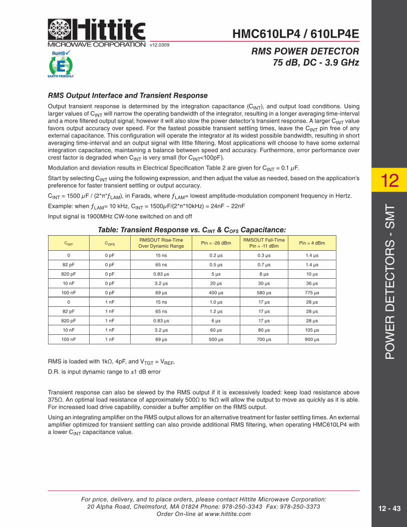
RMS Output Interface and Transient Response
Output transient response is determined by the integration capacitance (CINT), and output load conditions. Using larger values of CINT will narrow the operating bandwidth of the integrator, resulting in a longer averaging time-interval and a more fi ltered output signal; however it will also slow the power detector’s transient response. A larger CINT value favors output accuracy over speed. For the fastest possible transient settling times, leave the CINT pin free of any external capacitance. This confi guration will operate the integrator at its widest possible bandwidth, resulting in short averaging time-interval and an output signal with little fi ltering. Most applications will choose to have some external integration capacitance, maintaining a balance between speed and accuracy. Furthermore, error performance over crest factor is degraded when CINT is very small (for CINT<100pF).
Modulation and deviation results in Electrical Specifi cation Table 2 are given for CINT = 0.1 μF.
Start by selecting CINT using the following expression, and then adjust the value as needed, based on the application’s preference for faster transient settling or output accuracy.
CINT = 1500 μF / (2*π*ƒLAM), in Farads, where ƒLAM= lowest amplitude-modulation component frequency in Hertz.
Example: when ƒLAM= 10 kHz, CINT = 1500μF/(2*π*10kHz) = 24nF ~ 22nF
Input signal is 1900MHz CW-tone switched on and off
RMS is loaded with 1kΩ, 4pF, and VTGT = VREF,
D.R. is input dynamic range to ±1 dB error
Transient response can also be slewed by the RMS output if it is excessively loaded: keep load resistance above 375Ω. An optimal load resistance of approximately 500Ω to 1kΩ will allow the output to move as quickly as it is able. For increased load drive capability, consider a buffer amplifi er on the RMS output.
Using an integrating amplifi er on the RMS output allows for an alternative treatment for faster settling times. An external amplifi er optimized for transient settling can also provide additional RMS fi ltering, when operating HMC610LP4 with a lower CINT capacitance value.
Table: Transient Response vs. CINT & COFS Capacitance:
CINT COFSRMSOUT Rise-TimeOver Dynamic Range
Pin = -26 dBmRMSOUT Fall-Time
Pin = -11 dBmPin = 4 dBm
0 0 pF 15 ns 0.2 μs 0.3 μs 1.4 μs
82 pF 0 pF 65 ns 0.5 μs 0.7 μs 1.4 μs
820 pF 0 pF 0.83 μs 5 μs 8 μs 10 μs
10 nF 0 pF 3.2 μs 20 μs 30 μs 36 μs
100 nF 0 pF 69 μs 400 μs 580 μs 775 μs
0 1 nF 15 ns 1.0 μs 17 μs 28 μs
82 pF 1 nF 65 ns 1.2 μs 17 μs 28 μs
820 pF 1 nF 0.83 μs 6 μs 17 μs 28 μs
10 nF 1 nF 3.2 μs 60 μs 80 μs 105 μs
100 nF 1 nF 69 μs 500 μs 700 μs 900 μs
HMC610LP4 / 610LP4Ev12.0309
RMS POWER DETECTOR
75 dB, DC - 3.9 GHz

For price, delivery, and to place orders, please contact Hittite Microwave Corporation:20 Alpha Road, Chelmsford, MA 01824 Phone: 978-250-3343 Fax: 978-250-3373
Order On-line at www.hittite.com
PO
WE
R D
ET
EC
TO
RS
- S
MT
12
12 - 44
Log-Slope and Intercept
The HMC610LP4 is set with a Pin –> RMS transfer characteristic slope set to 36.5mV/dBm by design (otherwise referred to as the log-slope). Connect the RMS pin directly to VSET pin. The Pin –> RMS transfer characteristic is not adjustable internally, but both slope and intercept can be adjusted quite easily by using an external integrating amplifi er such as the one shown below. Avoid loading the RMS output with a capacitive load above 35pF, when CINT<100pF.
Figure: External Integrating Amplifi er with log-slope and log-intercept control.
VINTERCEPT is a DC voltage used to adjust the log-intercept point.
VOUT(s)= RMSOUT X (1 + G(s)) - VINTERCEPT X G(s), V
, Hz = cut-off frequency
Rf is in OhmsCf is in Farads
DC Offset Compensation Loop
Internal DC offsets, which are input signal dependant, require continuous cancellation. Offset cancellation is a critical function needed for maintenance of measurement accuracy and sensitivity. The DC offset cancellation loop performs this function, and its response is largely defi ned by the capacitance off the COFS pin. Setting DC offset cancellation, loop bandwidth strives to strike a balance between offset cancellation accuracy, and loop response time. A larger value of COFS results in a more precise offset cancellation, but at the expense of a slower offset cancellation response. A smaller value of COFS tilts the performance trade-off towards a faster offset cancellation response. The optimal loop bandwidth setting will allow internal offsets to be cancelled at a minimally acceptable speed.
DC Offset Cancellation Loop ≈ Bandwidth , Hz
For example: loop bandwidth for DC cancellation with COFS = 1nF, bandwidth is ~62 kHz
Note:The measurement error produced by internal DC offsets cannot be measured at any single operating point, in terms of input signal frequency and level, with repeatability. Measurement error must be calculated to a best fi t line, over the entire operating range (again, in terms of signal level and frequency).
HMC610LP4 / 610LP4Ev12.0309
RMS POWER DETECTOR
75 dB, DC - 3.9 GHz
Standby Mode
The ENX can be used to force the power detector into a low-power standby mode. In this mode, the entire power detector is powered-down. As ENX is deactivated, power is restored to all of the circuits. There is no memory of previous conditions. Coming-out of stand-by, CINT and COFS capacitors will require recharging, so if large capacitor values have been chosen, the wake-up time will be lengthened.

For price, delivery, and to place orders, please contact Hittite Microwave Corporation:20 Alpha Road, Chelmsford, MA 01824 Phone: 978-250-3343 Fax: 978-250-3373
Order On-line at www.hittite.com
PO
WE
R D
ET
EC
TO
RS
- S
MT
12
12 - 45
-40
-36
-32
-28
-24
-20
-16
-12
-8
-4
0
4
2 4 6 8 10 12 14 16
VTGT
= 0.5V
VTGT
= 1.25V
VTGT
= 2.0V
VTGT
= 2.75V
VTGT
= 3.50VRM
SO
UT
ER
RO
R (
dB)
CREST FACTOR (dB)
RMS Output Error vs. Crest Factor**Worst Case Conditions**
using circuit described in “ Application & Evaluation PCB Schematic” section
System Calibration
Due to part-to-part variations in log-slope and log-intercept, a system-level calibration is recommended to satisfy absolute accuracy requirements. When performing this calibration, choose at least two test points: near the top end and bottom-end of the measurement range. It is best to measure the calibration points in the regions (of frequency and amplitude) where accuracy is most important. Derive the log-slope and log-intercept, and store them in non-volatile memory.
HMC610LP4 / 610LP4Ev12.0309
RMS POWER DETECTOR
75 dB, DC - 3.9 GHz
Adjusting VTGT for greater precision
There are two competing aspects of performance, for which VTGT can be used to set a preference. Depending on which aspect of precision is more important to the application, the VTGT pin can be used to fi nd a compromise between two sources of RMS output error: internal DC offset cancellation error and deviation at high crest factors (>10 dB).
• Increasing VTGT input voltage will improve internal DC offset cancellation, but deviation at high crest factors will increase slightly. A 50% increase in VTGT should produce an 18% improvement in RMS precision due to improved DC offset cancellation performance.
• Decreasing VTGT input voltage will reduce errors at high crest factors, but DC offset cancellation performance will be slightly degraded. See “RMS Output Error vs. Crest Factor” graph.
If input signal crest factor is not expected to exceed 10 dB, you can improve RMS precision by increasing VTGT voltage. Keep in mind that changing VTGT also adjusts the log-intercept point, which shifts the “input dynamic range”. The best set-point for VTGT will be the lowest voltage that still maintains the “input dynamic range” over the required range of input power. This new VTGT set-point should optimize DC offset correction performance.
If error performance for crest factors >10 dB requires optimization, set VTGT for the maximum tolerable error at the highest expected crest factor. Increasing VTGT beyond that point will unnecessarily compromise internal DC offset cancellation performance. After changing VTGT, re-verify that the “input dynamic range” still covers the required range of input power.
VTGT should be referenced to VREF for best performance. It is recommended to use a temperature stable DC amplifi er between VTGT and VREF to create VTGT > VREF. The VREF pin is a temperature compensated voltage reference output, only intended for use with VTGT.
VT Error due to Internal DC Offsets
1.0V Nominal +0.2 dB
1.5V Nominal +0.1 dB
2.0V Nominal
3.0V Nominal -0.06 dB
3.5V Nominal -0.1 dB
VTGT
Infl uence on DC Offset Compensation

For price, delivery, and to place orders, please contact Hittite Microwave Corporation:20 Alpha Road, Chelmsford, MA 01824 Phone: 978-250-3343 Fax: 978-250-3373
Order On-line at www.hittite.com
PO
WE
R D
ET
EC
TO
RS
- S
MT
12
12 - 46
HMC610LP4 / 610LP4Ev12.0309
RMS POWER DETECTOR
75 dB, DC - 3.9 GHz
System Calibration (Continued)
For example if the following two calibration points were measured at 2.35 GHz:
With Vrms = 2.34V at Pin= -7dBm,
and Vrms=1.84V at Pin= -16dBm
slope calibration constant = SCC
SCC = (-16+7)/(1.84-2.34) = 18 dB/V
intercept calibration constant = ICC
ICC = Pin – SCC*Vrms = -7 – 18.0 * 2.34 = -49.12dBm
Now performing a power measurement:
Vrms measures 2.13V
[Measured Pin] = [Measured Vrms]*SCC + ICC
[Measured Pin] = 2.13*18.0 – 49.12 = -10.78dBm
An error of only 0.22dB
Factory system calibration measurements should be made using an input signal representative of the application. If the power detector will operate over a wide range of frequencies, choose a central frequency for calibration.
Layout Considerations
• Mount RF input coupling capacitors close to the IN+ and IN- pins.
• Solder the heat slug on the package underside to a grounded island which can draw heat away from the diewith low thermal impedance. The grounded island should be at RF ground potential.
• Connect power detector ground to the RF ground plane, and mount the supply decoupling capacitors closeto the supply pins.
Defi nitions:
• Log-slope: slope of PIN –> VRMS transfer characteristic. In units of mV/dB
• Log-intercept: x-axis intercept of PIN –> VRMS transfer characteristic. In units of dBm.
• RMS Output Error: The difference between the measured PIN and actual PIN using a line of best fi t.
[measured_PIN] = [measured_VRMS] / [best-fi t-slope] + [best-fi t-intercept], dBm
• Input Dynamic Range: the range of average input power for which there is a corresponding RMS outputvoltage with “RMS Output Error” falling within a specifi c error tolerance.
• Crest Factor: Peak power to average power ratio for time-varying signals.

For price, delivery, and to place orders, please contact Hittite Microwave Corporation:20 Alpha Road, Chelmsford, MA 01824 Phone: 978-250-3343 Fax: 978-250-3373
Order On-line at www.hittite.com
PO
WE
R D
ET
EC
TO
RS
- S
MT
12
12 - 47
HMC610LP4 / 610LP4Ev12.0309
RMS POWER DETECTOR
75 dB, DC - 3.9 GHz
Notes: