rider'smanual k1600gtl - bmw motorrad ישראל
TRANSCRIPT
Rider's Manual
K 1600GTL
BMW Motorrad
Vehicle data/dealership details
Vehicle data
Model
Vehicle Identification Number
Colour code
Date of first registration
Registration number
Dealership details
Person to contact in Service department
Ms/Mr
Phone number
Dealership address/phone number (com-pany stamp)
Welcome to BMW
We congratulate you onyour choice of a vehicle fromBMW Motorrad and welcomeyou to the community of BMWriders. Familiarise yourself withyour new vehicle so that you canride it safely and confidently in alltraffic situations.
About these operatinginstructionsRead these operating instructionscarefully before starting to useyour new BMW. They containimportant information on how tooperate the controls and how tomake the best possible use of allyour BMW's technical features.In addition, they contain informa-tion on maintenance and care tohelp you maintain your vehicle'sreliability and safety, as well as itsvalue.
The record of the maintenancework you have had performed onyour vehicle is a precondition forgenerous treatment of goodwillclaims.If the time comes to sell yourBMW, please remember to handover these operating instructionsto the new owner. They are animportant part of the vehicle.
Suggestions and criticismIf you have questions concern-ing your vehicle, your authorisedBMW Motorrad retailer will gladlyprovide advice and assistance.
We hope you will enjoy ridingyour BMW and that all your jour-neys will be pleasant and safe
BMW Motorrad.
01 40 1 614 831
*01401614831**01401614831**01401614831*
Table of Contents
1 General instructions . . . . 5Overview . . . . . . . . . . . . . . . . . . . . . 6Abbreviations andsymbols . . . . . . . . . . . . . . . . . . . . . . 6Equipment . . . . . . . . . . . . . . . . . . . 7Technical data . . . . . . . . . . . . . . . 7Currency . . . . . . . . . . . . . . . . . . . . . 8Additional sources of informa-tion . . . . . . . . . . . . . . . . . . . . . . . . . . . 8Certificates and operating li-cences . . . . . . . . . . . . . . . . . . . . . . . 8Data memory. . . . . . . . . . . . . . . . . 8Intelligent emergency callsystem . . . . . . . . . . . . . . . . . . . . . . 13
2 General views . . . . . . . . . . . 17General view, left side . . . . . . . 19General view, right side . . . . . 21General overview, top . . . . . . . 22Underneath the seat . . . . . . . . 23Multifunction switch, left . . . . 24Multifunction switch,right . . . . . . . . . . . . . . . . . . . . . . . . . 25
Multifunction switch,right . . . . . . . . . . . . . . . . . . . . . . . . . 26Operating panel . . . . . . . . . . . . . 27Instrument panel . . . . . . . . . . . . 29
3 Status indicators . . . . . . . 31Indicator and warninglights . . . . . . . . . . . . . . . . . . . . . . . . 32Meaning of symbols . . . . . . . . . 33Multifunction display . . . . . . . . 35Warning indicators . . . . . . . . . . 36
4 Operation. . . . . . . . . . . . . . . . 61Ignition switch/steeringlock . . . . . . . . . . . . . . . . . . . . . . . . . 62Ignition . . . . . . . . . . . . . . . . . . . . . . 62Ignition with Key-less Ride . . . . . . . . . . . . . . . . . . . . 63Electronic immobiliserEWS . . . . . . . . . . . . . . . . . . . . . . . . 66Emergency off switch (killswitch) . . . . . . . . . . . . . . . . . . . . . . 67Intelligent emergencycall . . . . . . . . . . . . . . . . . . . . . . . . . . 68Reverser . . . . . . . . . . . . . . . . . . . . 70
Lights . . . . . . . . . . . . . . . . . . . . . . . 71Daytime riding light . . . . . . . . . . 74Hazard warning lights . . . . . . . 75Turn indicators . . . . . . . . . . . . . . 76Multifunction display . . . . . . . . 76On-board computer . . . . . . . . . 81Trip recorder . . . . . . . . . . . . . . . . 82Anti-theft alarm (DWA) . . . . . . 83Dynamic Traction Control(DTC) . . . . . . . . . . . . . . . . . . . . . . . 87Electronic Suspension Ad-justment (DESA) . . . . . . . . . . . 87Riding mode . . . . . . . . . . . . . . . . 88Cruise-control system . . . . . . . 89Hill Start Control . . . . . . . . . . . . 91Central locking system . . . . . . 92Grip heating . . . . . . . . . . . . . . . . . 96Seat heating . . . . . . . . . . . . . . . . 97Seat . . . . . . . . . . . . . . . . . . . . . . . . . 98Storage compartments . . . . . . 99
5 Audio system .. . . . . . . . 101General operation . . . . . . . . . 102Radio . . . . . . . . . . . . . . . . . . . . . . 109Satellite radio . . . . . . . . . . . . . . 114
External playbackdevices . . . . . . . . . . . . . . . . . . . . 119Audio playback . . . . . . . . . . . . 122Bluetooth. . . . . . . . . . . . . . . . . . 123
6 Adjustment . . . . . . . . . . . . 129Mirrors . . . . . . . . . . . . . . . . . . . . 130Windscreen . . . . . . . . . . . . . . . 130Slipstream deflector . . . . . . . 131Clutch . . . . . . . . . . . . . . . . . . . . . 131Brakes . . . . . . . . . . . . . . . . . . . . 132
7 Riding . . . . . . . . . . . . . . . . . . 133Safety information . . . . . . . . . 134Regular check . . . . . . . . . . . . . 136Starting. . . . . . . . . . . . . . . . . . . . 136Running in . . . . . . . . . . . . . . . . 138Brakes . . . . . . . . . . . . . . . . . . . . 139Parking your motor-cycle . . . . . . . . . . . . . . . . . . . . . . 141Refuelling . . . . . . . . . . . . . . . . . 142Securing motorcycle fortransportation . . . . . . . . . . . . . 146
8 Engineeringdetails . . . . . . . . . . . . . . . . . 149
General instructions . . . . . . . 150Antilock Brake System(ABS) . . . . . . . . . . . . . . . . . . . . . . 150Dynamic Traction Control(DTC) . . . . . . . . . . . . . . . . . . . . . 153Electronic Suspension Ad-justment (DESA) . . . . . . . . . 155Riding mode . . . . . . . . . . . . . . 155Tyre pressure monitoring(RDC) . . . . . . . . . . . . . . . . . . . . . 157Gear Shift Assistant . . . . . . . 158Hill Start Control . . . . . . . . . . 159Adaptive Headlight . . . . . . . . 160
9 Maintenance . . . . . . . . . . 161General instructions . . . . . . . 162Toolkit . . . . . . . . . . . . . . . . . . . . . 162Front-wheel stand . . . . . . . . . 162Engine oil . . . . . . . . . . . . . . . . . 164Brake system . . . . . . . . . . . . . 165Clutch . . . . . . . . . . . . . . . . . . . . . 170Coolant . . . . . . . . . . . . . . . . . . . . 170Tyres . . . . . . . . . . . . . . . . . . . . . . 171Rims and tyres . . . . . . . . . . . . 171
Wheels . . . . . . . . . . . . . . . . . . . . 172Lighting . . . . . . . . . . . . . . . . . . . 179Jump-starting . . . . . . . . . . . . . 185Battery . . . . . . . . . . . . . . . . . . . . 186Fuses . . . . . . . . . . . . . . . . . . . . . 190Diagnostic connector . . . . . . 191
10 Accessories . . . . . . . . . 193General notes . . . . . . . . . . . . . 194Power sockets . . . . . . . . . . . . 194Cases . . . . . . . . . . . . . . . . . . . . . 195Topcase. . . . . . . . . . . . . . . . . . . 197Navigation device . . . . . . . . . 200
11 Care . . . . . . . . . . . . . . . . . . 205Care products . . . . . . . . . . . . . 206Washing the vehicle . . . . . . . 206Cleaning easily damagedcomponents . . . . . . . . . . . . . . . 207Care of paintwork . . . . . . . . . 208Vehicle preservation . . . . . . . 208Laying up the motor-cycle . . . . . . . . . . . . . . . . . . . . . . 208Restoring motorcycle touse . . . . . . . . . . . . . . . . . . . . . . . . 209

12 Technical data . . . . . . 211Troubleshooting chart . . . . . 212Threaded fasteners . . . . . . . 213Fuel . . . . . . . . . . . . . . . . . . . . . . . 215Engine oil . . . . . . . . . . . . . . . . . 216Engine . . . . . . . . . . . . . . . . . . . . 216Clutch . . . . . . . . . . . . . . . . . . . . . 217Transmission . . . . . . . . . . . . . . 218Final drive . . . . . . . . . . . . . . . . . 218Frame . . . . . . . . . . . . . . . . . . . . . 219Suspension . . . . . . . . . . . . . . . 219Brakes . . . . . . . . . . . . . . . . . . . . 220Wheels and tyres. . . . . . . . . . 221Electrical system . . . . . . . . . . 223Anti-theft alarm. . . . . . . . . . . . 224Dimensions . . . . . . . . . . . . . . . 225Weights . . . . . . . . . . . . . . . . . . . 226Performance figures . . . . . . . 226Radio . . . . . . . . . . . . . . . . . . . . . . 227MP3. . . . . . . . . . . . . . . . . . . . . . . 227Bluetooth. . . . . . . . . . . . . . . . . . 228External audio devices . . . . 228Speakers . . . . . . . . . . . . . . . . . . 228
13 Service . . . . . . . . . . . . . . . 229BMW Motorrad Service . . . 230BMW Motorrad Servicehistory . . . . . . . . . . . . . . . . . . . . . 230BMW Motorrad Mobilityservices . . . . . . . . . . . . . . . . . . . 231Maintenance work . . . . . . . . . 231Maintenance schedule . . . . 235Maintenance confirma-tions . . . . . . . . . . . . . . . . . . . . . . . 236Service confirmations . . . . . 250
14 Appendix. . . . . . . . . . . . . 253Declaration of conform-ity for electronic immobil-iser . . . . . . . . . . . . . . . . . . . . . . . . 254Certificate for electronicimmobiliser . . . . . . . . . . . . . . . . 260Certificate for remote con-trol . . . . . . . . . . . . . . . . . . . . . . . . 262Declaration of conformityfor Keyless Ride . . . . . . . . . . . 266Certificate for Key-less Ride . . . . . . . . . . . . . . . . . . 271Declaration of conformityfor tyre pressure control(RDC) . . . . . . . . . . . . . . . . . . . . . 273
Certificate for tyre pressuremonitoring (Reifendruck-Control, RDC) . . . . . . . . . . . . . 280Declaration of conformityfor intelligent emergencycall . . . . . . . . . . . . . . . . . . . . . . . . 281Declaration of conform-ity for anti-theft alarm sys-tem . . . . . . . . . . . . . . . . . . . . . . . 287Certificate for audio sys-tem . . . . . . . . . . . . . . . . . . . . . . . 293Certificate for audio sys-tem . . . . . . . . . . . . . . . . . . . . . . . 299
15 Index . . . . . . . . . . . . . . . . . 305
General instructions
Overview . . . . . . . . . . . . . . . . . . . . . . . . . . . . 6
Abbreviations and symbols . . . . . . . . . . 6
Equipment . . . . . . . . . . . . . . . . . . . . . . . . . . . 7
Technical data . . . . . . . . . . . . . . . . . . . . . . . 7
Currency . . . . . . . . . . . . . . . . . . . . . . . . . . . . . 8
Additional sources of information . . . . 8
Certificates and operatinglicences . . . . . . . . . . . . . . . . . . . . . . . . . . . . . . 8
Data memory . . . . . . . . . . . . . . . . . . . . . . . . 8
Intelligent emergency callsystem . . . . . . . . . . . . . . . . . . . . . . . . . . . . . . 13
15
z Ge
ne
ral i
nst
ruc
tio
ns
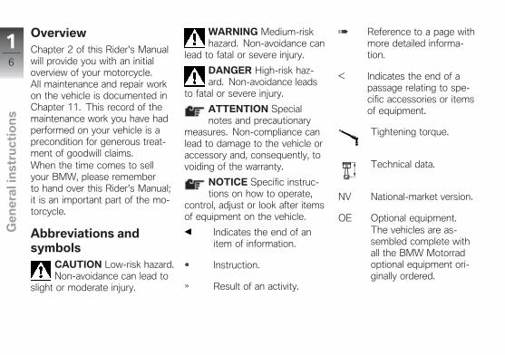
OverviewChapter 2 of this Rider's Manualwill provide you with an initialoverview of your motorcycle.All maintenance and repair workon the vehicle is documented inChapter 11. This record of themaintenance work you have hadperformed on your vehicle is aprecondition for generous treat-ment of goodwill claims.When the time comes to sellyour BMW, please rememberto hand over this Rider's Manual;it is an important part of the mo-torcycle.
Abbreviations andsymbols
CAUTION Low-risk hazard.Non-avoidance can lead to
slight or moderate injury.
WARNING Medium-riskhazard. Non-avoidance can
lead to fatal or severe injury.
DANGER High-risk haz-ard. Non-avoidance leads
to fatal or severe injury.
ATTENTION Specialnotes and precautionary
measures. Non-compliance canlead to damage to the vehicle oraccessory and, consequently, tovoiding of the warranty.
NOTICE Specific instruc-tions on how to operate,
control, adjust or look after itemsof equipment on the vehicle.
Indicates the end of anitem of information.
Instruction.
Result of an activity.
Reference to a page withmore detailed informa-tion.
Indicates the end of apassage relating to spe-cific accessories or itemsof equipment.
Tightening torque.
Technical data.
NV National-market version.
OE Optional equipment.The vehicles are as-sembled complete withall the BMW Motorradoptional equipment ori-ginally ordered.
16
z Ge
ne
ral i
nst
ruc
tio
ns
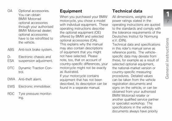
OA Optional accessories.You can obtainBMW Motorradoptional accessoriesthrough your authorisedBMW Motorrad dealer;optional accessorieshave to be retrofitted tothe vehicle.
ABS Anti-lock brake system.
D-ESA
Electronic chassis andsuspension adjustment.
DTC Dynamic Traction Con-trol.
DWA Anti-theft alarm.
EWS Electronic immobiliser.
RDC Tyre pressure monitor-ing.
EquipmentWhen you purchased your BMWmotorcycle, you chose a modelwith individual equipment. Theseoperating instructions describethe optional equipment (OE)offered by BMW and selectedoptional accessories (OA).This explains why the manualmay also contain descriptionsof equipment that you mightnot have selected. Pleasenote, too, that on account ofcountry-specific differences, yourmotorcycle might not be exactlyas illustrated.If your motorcycle containsequipment that has not beendescribed, its description can befound in a separate manual.
Technical dataAll dimensions, weights andpower ratings stated in theoperating instructions are quotedto the standards and comply withthe tolerance requirements of theDeutsches Institut für Normunge.V. (DIN).Technical data and specificationsin this rider's manual serve asreference points. The vehicle-specific data may deviate fromthese, for example as a result ofselected optional equipment,the national-market version orcountry-specific measuringprocedures. Detailed valuescan be taken from the vehicleregistration documents andsigns on the vehicle, or can beobtained from your authorisedBMW Motorrad retailer oranother qualified service partneror specialist workshop. Thespecifications in the vehicledocuments always have priority
17
z Ge
ne
ral i
nst
ruc
tio
ns
over the information provided inthis rider's manual.
CurrencyThe high safety and qualitystandards of BMW motorcyclesare maintained by constantdevelopment work on designs,equipment and accessories.Because of this, your motorcyclemay differ from the informationsupplied in the Rider's Manual.Nor can BMW Motorrad entirelyrule out errors and omissions.We hope you will appreciate thatno claims can be entertained onthe basis of the data, illustrationsor descriptions in these operatinginstructions.
Additional sources ofinformationAuthorised BMW MotorradretailerYour BMW Motorrad retailer willbe happy to answer any ques-tions you may have.
InternetThe operating instructions foryour vehicle, operating andinstallation instructions for ac-cessories and general informationabout BMW Motorrad, in relationto technology, for example, areavailable for download fromwww.bmw-motorrad.com/manuals.
Certificates andoperating licencesThe certificates for the vehicleand the official operatinglicences for accessories canbe downloaded from bmw-motorrad.com/certification.
Data memoryGeneralControl units are installed in thevehicle. Control units processdata that they receive, for ex-ample, from vehicle sensors, orthat they generate themselves orexchange between each other.Some control units are requiredfor the vehicle to function safelyor provide assistance during rid-ing, for example assistance sys-tems. In addition, control unitsenable comfort or infotainmentfunctions.Information on data that hasbeen stored or exchanged can
18
z Ge
ne
ral i
nst
ruc
tio
ns

be obtained from the manufac-turer of the vehicle, for examplevia a separate booklet.
Personal referenceEach vehicle is identified with aclear vehicle identification num-ber. Depending on the country,the vehicle identification num-ber, the number plate and thecorresponding authorities canbe referenced to ascertain thevehicle owner. There are alsoother ways to use data obtainedfrom the vehicle to trace the rideror vehicle owner, for exampleusing the ConnectedDrive useraccount.
Data protection rightsIn accordance with applicabledata protection laws, vehicleusers have certain rights in re-lation to the manufacturer of thevehicle or in relation to compan-
ies which collect or process per-sonal data.Vehicle users have the right toobtain full information at no costfrom persons or entities storingpersonal data of the vehicle user.These entities may include:
Manufacturer of the vehicleQualified service partnersSpecialist workshopsService providers
Vehicle users have the right torequest information on what per-sonal data has been stored, forwhat purpose the data is used,and where the data comes from.To obtain this information, proofof ownership or use is required.The right to information also in-cludes information about datathat has been shared with othercompanies or entities.The website of the vehicle man-ufacturer contains the applicabledata protection information. This
data protection information in-cludes information on the right tohave data deleted or corrected.The manufacturer of the vehiclealso provides their contact detailsand those of the data protectionofficer on their website.The vehicle owner can also re-quest that a BMW Motorrad re-tailer or another qualified servicepartner or specialist workshopread out the data that is stored inthe vehicle for a charge.The vehicle data is read out us-ing the legally prescribed socketfor on-board diagnosis (OBD) inthe vehicle.
Legal requirements for thedisclosure of dataAs part of its legal responsib-ilities, the manufacturer of thevehicle is obligated to make itsstored data available to the rel-evant authorities. This data isprovided in the required scope in
19
z Ge
ne
ral i
nst
ruc
tio
ns
individual cases, for example toclarify a criminal offence.In the context of applicable laws,public agencies are entitled inindividual cases to read out datafrom the vehicle themselves.
Operating data in the vehicleControl units process data to op-erate the vehicle.This includes, for example:
Status reports of the vehicleand its individual components,for example wheel revolutions,wheel speed, decelerationEnvironmental conditions, forexample temperature
The data is only processed inthe vehicle itself and is gener-ally non-permanent. The data isnot stored beyond the operatingperiod.Electronic components, for ex-ample control units, contain com-ponents for storing technical in-
formation. Information can betemporarily or permanently storedon the vehicle condition, com-ponent loads, incidents or errors.This information is generally usedto document the condition of acomponent, a module, a systemor the surrounding area, for ex-ample:
Operating conditions of systemcomponents, for example fillinglevels, tyre pressureMalfunctions and faults in im-portant system components,for example light and brakesResponse of the vehicle inspecial riding situations, forexample engagement of thedriving dynamics systemsInformation on incidents result-ing in damage to the vehicle
The data is necessary for theprovision of control unit functions.Furthermore, the data is used todetect and rectify malfunctions
and to enable the vehicle manu-facturer to optimise vehicle func-tions.The vast majority of this data isnon-permanent and is only pro-cessed in the vehicle itself. Onlya small amount of the data isstored in incident or fault memor-ies as required by events.If services are accessed, for ex-ample repairs, service processes,warranty cases and quality assur-ance measures, this technical in-formation can be read out of thevehicle together with the vehicleidentification number.The information can be read outby a BMW Motorrad retailer oranother qualified service part-ner or specialist workshop. Thelegally stipulated socket for on-board diagnosis (OBD) in thevehicle is used to read out thedata.The data is obtained, processedand used by the relevant parts of
110
z Ge
ne
ral i
nst
ruc
tio
ns
the retailer network. The data isused to document the technicalconditions of the vehicle, to helpwith error localization, to complywith warranty obligations and toimprove quality.In addition, the manufacturer hasvarious product monitoring ob-ligations arising from product li-ability legislation. To meet theseobligations, the vehicle manu-facturer requires technical datafrom the vehicle. The data fromthe vehicle can also be used tocheck warranty claims from thecustomer.Error and incident memories inthe vehicle can be reset dur-ing servicing or repair work bya BMW Motorrad retailer or an-other qualified service partner orspecialist workshop.
Data input and data transferin the vehicleGeneralDepending on the equipment,comfort and customised settingscan be stored in the vehicle andcan be changed or reset at anytime.This includes, for example:
Settings of the windscreen po-sitionChassis and suspension set-tings
If required, data can be enteredin the entertainment and commu-nication system of the vehicle, forexample using a smartphone.Depending on the individualequipment, this includes:
Multimedia data, such as musicfor playbackContacts data for use in con-nection with a communicationsystem or an integrated naviga-tion system
Entered destinationsData on the use of internetservices. This data can bestored locally in the vehicleor is located on a device thatis connected to the vehicle,for example smartphone, USBstick, MP3 player. If this data isstored in the vehicle, the datacan be deleted at any time.
This data is transferred to thirdparties only if personally reques-ted within the context of usingonline services. This depends onthe selected settings when usingthe services.Incorporation of mobiledevicesDepending on the equipment,mobile devices connected tothe vehicle, for example smart-phones, can be controlled usingthe operating elements of thevehicle.
111
z Ge
ne
ral i
nst
ruc
tio
ns
The image and sound of the mo-bile device can then be outputvia the multimedia system. Atthe same time, specific informa-tion is transferred to the mobiledevice. Depending on the typeof integration, this includes, forexample, position data and addi-tional general vehicle information.This enables optimal use of theselected apps, for example navig-ation or music playback.The type of additional data pro-cessing is determined by theprovider of the respective app.The scope of the possible set-tings depends on the corres-ponding app and the operatingsystem of the mobile device.
ServicesGeneralIf the vehicle has a wireless con-nection, this enables the ex-change of data between thevehicle and other systems. The
wireless connection is enabledby the vehicle's own transmitterand receiver unit or using per-sonally integrated mobile devices,for example smartphones. On-line functions can be used usingthis wireless connection. Theseinclude online services and appsthat are provided by the vehiclemanufacturer or by other pro-viders.Services of the vehicle manu-facturerFor online services of the vehiclemanufacturer, the individualfunctions are described atsuitable points, for examplerider's manual, website of themanufacturer. At the same time,information is also provided onthe relevant data protection law.Personal data may be used toprovide online services. Datais exchanged using a secureconnection, for example with
the IT systems provided by thevehicle manufacturer.Obtaining, processing and us-ing personal data outside of thenormal provision of services re-quires legal permission, contrac-tual agreement or consent. It isalso possible to have the entiredata connection activated or de-activated. Statutory functions areexcluded from this.Services from other providersWhen using online services fromother providers, these servicesare subject to the responsibil-ity and the data protection andoperating conditions of the indi-vidual provider. The vehicle man-ufacturer has no influence on thecontent that is exchanged in thisinstance. Information on the type,scope and purpose of the datacapture and use of personal dataas part of the services of thirdparties can be ascertained fromthe individual provider.
112
z Ge
ne
ral i
nst
ruc
tio
ns
Intelligent emergencycall system
with intelligent emergencycall OE
PrincipleThe intelligent emergency callsystem enables manual or auto-matic emergency calls, for ex-ample in the event of an acci-dent.The emergency calls are re-ceived by an emergency callcentre that is commissioned bythe vehicle manufacturer.For information on operating theintelligent emergency call systemand its functions, please refer to"Intelligent emergency call".
Legal basisProcessing of personal data us-ing the intelligent emergency callsystem is in line with the follow-ing regulations:
Protection of personal data:Directive 95/46/EC of theEuropean Parliament and of theCouncil.
Protection of personal data:Directive 2002/58/EC of theEuropean Parliament and of theCouncil.
The legal basis for the activa-tion and function of the intelli-gent emergency call system isthe concluded ConnectedRidecontract for this function, as wellas the corresponding laws, or-dinances and directives of theEuropean Parliament and of theEuropean Council.The relevant ordinances and dir-ectives regulate the protection ofnatural persons during the pro-cessing of personal data.The processing of personal databy the intelligent emergency callsystem satisfies the European
directives for the protection ofpersonal data.The intelligent emergency callsystem processes personal dataonly with the agreement of thevehicle owner.The intelligent emergency callsystem and other services withadditional benefits can processpersonal data only with the ex-press permission of the personaffected by the data processing,for example the vehicle owner.
SIM cardThe intelligent emergency callsystem operates via the mobilephone network using the SIMcard installed in the vehicle. TheSIM card is permanently loggedinto the mobile phone network toenable rapid connection setup.Data is sent to the vehicle manu-facturer in the event of an emer-gency.
113
z Ge
ne
ral i
nst
ruc
tio
ns
Improving qualityThe data that is transferred inan emergency is also used bythe manufacturer of the vehicleto improve product and servicequality.
Location determinationThe position of the vehicle canbe determined exclusively by themobile phone network providerbased on the mobile phone sitelocations. It is not possible forthe provider to trace a connec-tion between the vehicle's VINand the phone number of the in-stalled SIM card. Only the man-ufacturer of the vehicle can linka VIN and the phone number ofthe SIM card installed in a partic-ular vehicle.
Log data of emergency callsThe log data of emergency callsis stored in a memory of thevehicle. The oldest log data is
regularly deleted. The log dataincludes, for example, informationon when and where an emer-gency call was made. In excep-tional cases, the log data can beread out of the vehicle memory.As a rule, log data is only readout following a court order, andthis is only possible if the corres-ponding devices are connecteddirectly to the vehicle.
Automatic emergency callThe system is designed so that,following a sufficiently seriousaccident, which is detected bysensors in the vehicle, an emer-gency call is automatically activ-ated.
Sent informationWhen making an emergency callusing the intelligent emergencycall system, the system forwardsthe same information to the des-ignated emergency call centre as
is forwarded to the public emer-gency operations centre by thestatutory emergency call systemeCall.In addition, the intelligent emer-gency call system sends the fol-lowing additional information toan emergency call centre com-missioned by the vehicle man-ufacturer and, if required, to theemergency services:
Accident data, for example thedirection of impact detectedby the vehicle sensors, to as-sist the emergency servicesresponse.Contact details, for example thephone number of the installedSIM card and the phone num-ber of the rider, if available, toenable rapid contact with thoseinvolved in the accident if re-quired.
114
z Ge
ne
ral i
nst
ruc
tio
ns
Data storageThe data for an activatedemergency call is stored inthe vehicle. The data containsinformation on the emergencycall, for example the location andtime of the emergency call.The voice recordings of theemergency call are stored at theemergency call centre.The voice recordings of the cus-tomer are stored for 24 hours incase details of the emergencycall need to be analysed. Afterthis, the voice recordings aredeleted. The voice recordingsof the employee of the emer-gency call centre are stored for24 hours for quality assurancepurposes.
Information on personal dataThe data that is processed aspart of the intelligent emergencycall is processed exclusively tocarry out the emergency call. As
part of its statutory obligation,the manufacturer of the vehicleprovides information about thedata that it has processed andany data that it still has stored.
115
z Ge
ne
ral i
nst
ruc
tio
ns

116
z Ge
ne
ral i
nst
ruc
tio
ns
General views
General view, left side . . . . . . . . . . . . . . . 19
General view, right side . . . . . . . . . . . . . 21
General overview, top . . . . . . . . . . . . . . . 22
Underneath the seat . . . . . . . . . . . . . . . . 23
Multifunction switch, left . . . . . . . . . . . . 24
Multifunction switch, right . . . . . . . . . . . 25
Multifunction switch, right . . . . . . . . . . . 26
Operating panel . . . . . . . . . . . . . . . . . . . . . 27
Instrument panel . . . . . . . . . . . . . . . . . . . . 29
217
z Ge
ne
ral v
iew
s
218
z Ge
ne
ral v
iew
s
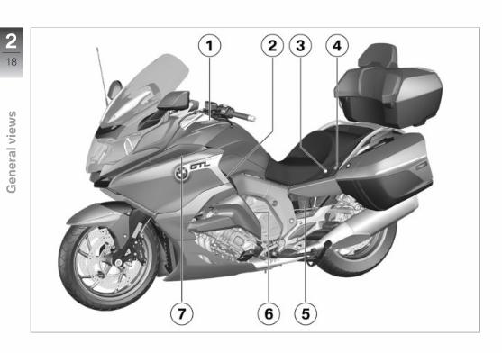
General view, left side1 Fuel filler neck ( 143)2 Operating unit for the
audio system3 Seat lock ( 98)4 Rocker switch for passen-
ger seat heating ( 97)5 Payload table
Tyre pressures table6 Storage compartment
( 99)7 Slipstream deflector
( 131)
219
z Ge
ne
ral v
iew
s

220
z Ge
ne
ral v
iew
s
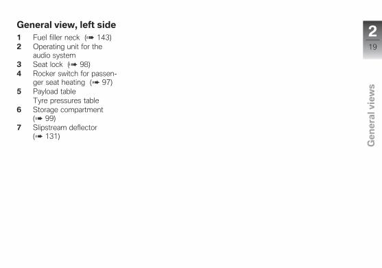
General view, right side1 Storage compartment
( 99)Connect the audio device( 120).
2 Power socket ( 194)3 Brake-fluid reservoir, front
( 168)4 Coolant level indicator (be-
hind side panel) ( 170)5 Type plate (on the front
suspension)6 Slipstream deflector
( 131)7 Engine number (above the
engine oil filler opening)Vehicle identification num-ber (above the engine oilfiller opening on the rearpart of the main frame)
8 Engine oil filler openingand oil dipstick ( 164)
9 Brake-fluid reservoir, rear( 169)
221
z Ge
ne
ral v
iew
s
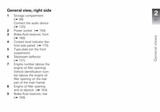
General overview, top1 Speakers2 Multifunction display
( 35)3 Operating panel ( 27)4 Multifunction switch, left
( 24)
222
z Ge
ne
ral v
iew
s
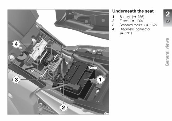
Underneath the seat1 Battery ( 186)2 Fuses ( 190)3 Standard toolkit ( 162)4 Diagnostic connector
( 191)
223
z Ge
ne
ral v
iew
s
Multifunction switch,left1 High-beam headlight and
headlight flasher ( 72)2 Daytime riding light
( 74)3 Cruise control ( 89)4 Hazard warning lights
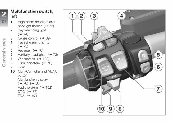
( 75)5 Reverser ( 70)6 Auxiliary headlights ( 73)7 Windscreen ( 130)8 Turn indicators ( 76)9 Horn10 Multi-Controller and MENU
buttonMultifunction display( 76) ( 80)Audio system ( 102)DTC ( 87)ESA ( 87)
224
z Ge
ne
ral v
iew
s
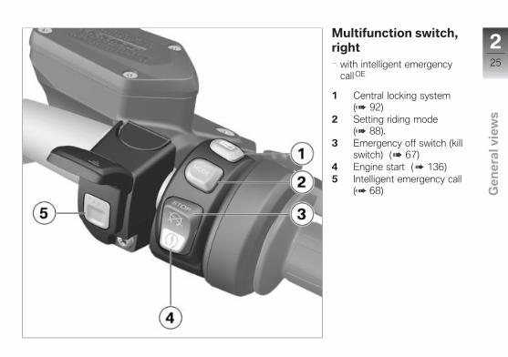
Multifunction switch,right
with intelligent emergencycall OE
1 Central locking system( 92)
2 Setting riding mode( 88).
3 Emergency off switch (killswitch) ( 67)
4 Engine start ( 136)5 Intelligent emergency call
( 68)
225
z Ge
ne
ral v
iew
s
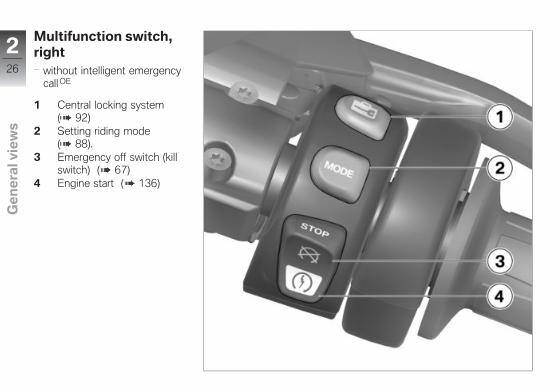
Multifunction switch,right
without intelligent emergencycall OE
1 Central locking system( 92)
2 Setting riding mode( 88).
3 Emergency off switch (killswitch) ( 67)
4 Engine start ( 136)
226
z Ge
ne
ral v
iew
s
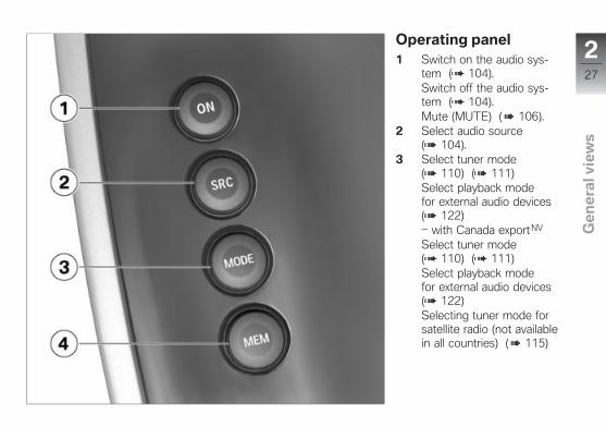
Operating panel1 Switch on the audio sys-
tem ( 104).Switch off the audio sys-tem ( 104).Mute (MUTE) ( 106).
2 Select audio source( 104).
3 Select tuner mode( 110) ( 111)Select playback modefor external audio devices( 122)
with Canada exportNV
Select tuner mode( 110) ( 111)Select playback modefor external audio devices( 122)Selecting tuner mode forsatellite radio (not availablein all countries) ( 115)
227
z Ge
ne
ral v
iew
s
4 Find and save stationsautomatically ( 109).Station save, manual( 110).
228
z Ge
ne
ral v
iew
s
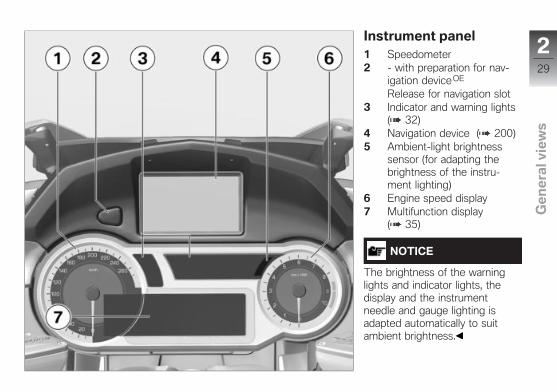
Instrument panel1 Speedometer2 - with preparation for nav-
igation deviceOE
Release for navigation slot3 Indicator and warning lights
( 32)4 Navigation device ( 200)5 Ambient-light brightness
sensor (for adapting thebrightness of the instru-ment lighting)
6 Engine speed display7 Multifunction display
( 35)
NOTICE
The brightness of the warninglights and indicator lights, thedisplay and the instrumentneedle and gauge lighting isadapted automatically to suitambient brightness.
229
z Ge
ne
ral v
iew
s

230
z Ge
ne
ral v
iew
s
Status indicators
Indicator and warning lights . . . . . . . . . 32
Meaning of symbols . . . . . . . . . . . . . . . . 33
Multifunction display . . . . . . . . . . . . . . . . 35
Warning indicators . . . . . . . . . . . . . . . . . . 36
331
z Sta
tus
ind
ica
tors
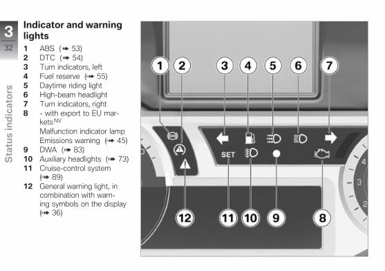
Indicator and warninglights1 ABS ( 53)2 DTC ( 54)3 Turn indicators, left4 Fuel reserve ( 55)5 Daytime riding light6 High-beam headlight7 Turn indicators, right8 - with export to EU mar-
kets NV
Malfunction indicator lampEmissions warning ( 45)
9 DWA ( 83)10 Auxiliary headlights ( 73)11 Cruise-control system
( 89)12 General warning light, in
combination with warn-ing symbols on the display( 36)
332
z Sta
tus
ind
ica
tors
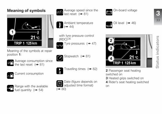
Meaning of symbols
Meaning of the symbols at repairposition 1:
Average consumption sincethe last reset ( 81)
Current consumption
Range with the availablefuel quantity ( 54)
Average speed since thelast reset ( 81)
Ambient temperature( 44)
with tyre pressure control(RDC)OE
Tyre pressures ( 47)
Stopwatch ( 81)
Travelling times ( 82)
Date (figure depends onadjusted time format)
( 80)
On-board voltage
Oil level ( 46)
2 Passenger seat heatingswitched on3 Heated grips switched on4 Rider's seat heating switchedon
333
z Sta
tus
ind
ica
tors
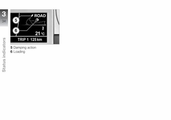
5 Damping action6 Loading
334
z Sta
tus
ind
ica
tors
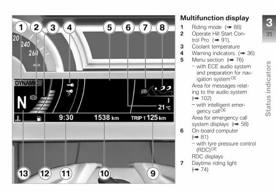
Multifunction display1 Riding mode ( 88)2 Operate Hill Start Con-
trol Pro ( 91).3 Coolant temperature4 Warning indicators ( 36)5 Menu section ( 76)
with ECE audio systemand preparation for nav-igation systemOE
Area for messages relat-ing to the audio system( 102)
with intelligent emer-gency call OE
Area for emergency callsystem displays ( 58)
6 On-board computer( 81)
with tyre pressure control(RDC)OE
RDC displays7 Daytime riding light
( 74)
335
z Sta
tus
ind
ica
tors
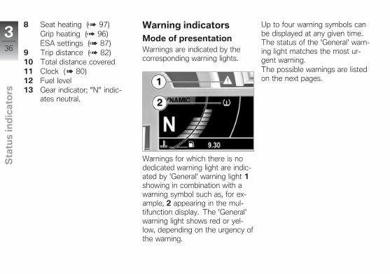
8 Seat heating ( 97)Grip heating ( 96)ESA settings ( 87)
9 Trip distance ( 82)10 Total distance covered11 Clock ( 80)12 Fuel level13 Gear indicator; "N" indic-
ates neutral.
Warning indicatorsMode of presentationWarnings are indicated by thecorresponding warning lights.
Warnings for which there is nodedicated warning light are indic-ated by 'General' warning light 1showing in combination with awarning symbol such as, for ex-ample, 2 appearing in the mul-tifunction display. The 'General'warning light shows red or yel-low, depending on the urgency ofthe warning.
Up to four warning symbols canbe displayed at any given time.The status of the 'General' warn-ing light matches the most ur-gent warning.The possible warnings are listedon the next pages.
336
z Sta
tus
ind
ica
tors
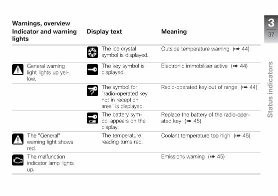
Warnings, overviewIndicator and warninglights
Display text Meaning
The ice crystalsymbol is displayed.
Outside temperature warning ( 44)
General warninglight lights up yel-low.
The key symbol isdisplayed.
Electronic immobiliser active ( 44)
The symbol for"radio-operated keynot in receptionarea" is displayed.
Radio-operated key out of range ( 44)
The battery sym-bol appears on thedisplay.
Replace the battery of the radio-oper-ated key ( 45)
The "General"warning light showsred.
The temperaturereading turns red.
Coolant temperature too high ( 45)
The malfunctionindicator lamp lightsup.
Emissions warning ( 45)
337
z Sta
tus
ind
ica
tors
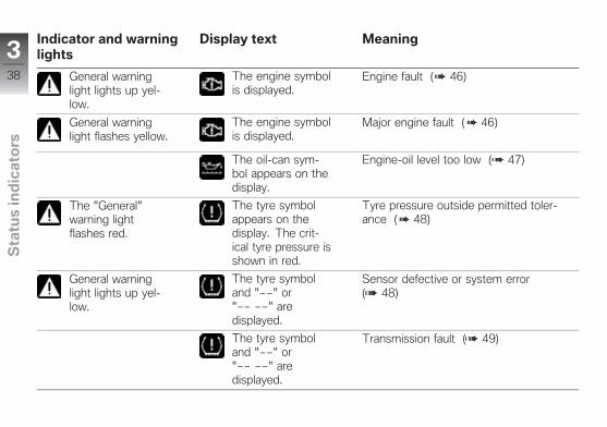
Indicator and warninglights
Display text Meaning
General warninglight lights up yel-low.
The engine symbolis displayed.
Engine fault ( 46)
General warninglight flashes yellow.
The engine symbolis displayed.
Major engine fault ( 46)
The oil-can sym-bol appears on thedisplay.
Engine-oil level too low ( 47)
The "General"warning lightflashes red.
The tyre symbolappears on thedisplay. The crit-ical tyre pressure isshown in red.
Tyre pressure outside permitted toler-ance ( 48)
General warninglight lights up yel-low.
The tyre symboland "" or" " aredisplayed.
Sensor defective or system error( 48)
The tyre symboland "" or" " aredisplayed.
Transmission fault ( 49)
338
z Sta
tus
ind
ica
tors
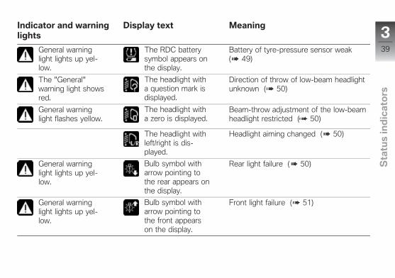
Indicator and warninglights
Display text Meaning
General warninglight lights up yel-low.
The RDC batterysymbol appears onthe display.
Battery of tyre-pressure sensor weak( 49)
The "General"warning light showsred.
The headlight witha question mark isdisplayed.
Direction of throw of low-beam headlightunknown ( 50)
General warninglight flashes yellow.
The headlight witha zero is displayed.
Beam-throw adjustment of the low-beamheadlight restricted ( 50)
The headlight withleft/right is dis-played.
Headlight aiming changed ( 50)
General warninglight lights up yel-low.
Bulb symbol witharrow pointing tothe rear appears onthe display.
Rear light failure ( 50)
General warninglight lights up yel-low.
Bulb symbol witharrow pointing tothe front appearson the display.
Front light failure ( 51)
339
z Sta
tus
ind
ica
tors

Indicator and warninglights
Display text Meaning
General warninglight lights up yel-low.
Bulb symbol withtwo arrows appearson the display.
Light failure ( 51)
The split batterysymbol appears onthe display.
On-board system voltage low ( 51)
General warninglight lights up yel-low.
The split batterysymbol appears onthe display.
On-board system voltage critical ( 51)
The "General"warning light showsred.
The battery sym-bol appears on thedisplay.
Insufficient battery charge current( 52)
The alarm sys-tem battery sym-bol appears on thedisplay.
Anti-theft alarm battery weak ( 52)
General warninglight lights up yel-low.
The alarm sys-tem battery sym-bol appears on thedisplay.
Anti-theft alarm battery flat ( 53)
340
z Sta
tus
ind
ica
tors
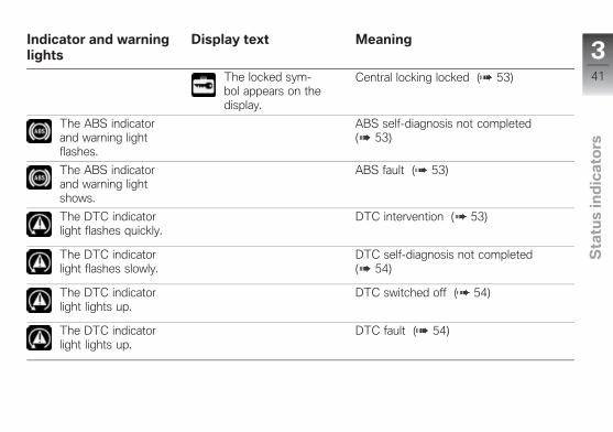
Indicator and warninglights
Display text Meaning
The locked sym-bol appears on thedisplay.
Central locking locked ( 53)
The ABS indicatorand warning lightflashes.
ABS self-diagnosis not completed( 53)
The ABS indicatorand warning lightshows.
ABS fault ( 53)
The DTC indicatorlight flashes quickly.
DTC intervention ( 53)
The DTC indicatorlight flashes slowly.
DTC self-diagnosis not completed( 54)
The DTC indicatorlight lights up.
DTC switched off ( 54)
The DTC indicatorlight lights up.
DTC fault ( 54)
341
z Sta
tus
ind
ica
tors
Indicator and warninglights
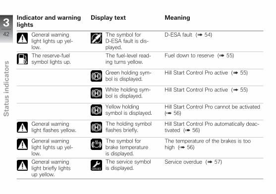
Display text Meaning
General warninglight lights up yel-low.
The symbol forDESA fault is dis-played.
DESA fault ( 54)
The reserve-fuelsymbol lights up.
The fuel-level read-ing turns yellow.
Fuel down to reserve ( 55)
Green holding sym-bol is displayed.
Hill Start Control Pro active ( 55)
White holding sym-bol is displayed.
Hill Start Control Pro active ( 55)
Yellow holdingsymbol is displayed.
Hill Start Control Pro cannot be activated( 56)
General warninglight flashes yellow.
The holding symbolflashes briefly.
Hill Start Control Pro automatically deac-tivated ( 56)
General warninglight lights up yel-low.
The symbol forbrake temperatureis displayed.
The temperature of the brakes is toohigh ( 56)
General warninglight briefly lightsup yellow.
The service symbolis displayed.
Service overdue ( 57)
342
z Sta
tus
ind
ica
tors

Indicator and warninglights
Display text Meaning
The symbol foremergency call faultis displayed.
Emergency call fault ( 57)
343
z Sta
tus
ind
ica
tors

Ambient temperatureWhen the motorcycle is ata standstill, the heat of the
engine can falsify the ambient-temperature reading. If the effectof the engine's heat becomes ex-cessive, "" temporarily appearson the display.
If the ambient tempera-ture drops to below 3 °C, a
warning of potential black ice ap-pears. Regardless of the displaysettings the display automaticallyswitches over to the temperaturedisplay when the ambient tempe-rature drops below this thresholdfor the first time.
Outside temperaturewarning
The ice crystal symbol isdisplayed.
Possible cause:The air temperature measured atthe vehicle is lower than 3 °C.
WARNING
Risk of black ice also applic-able at over 3 °CRisk of accident
Always take extra carewhen temperatures arelow; remember that there isparticular danger of black iceforming on bridges and wherethe road is in shade.
Ride carefully and think wellahead.
Electronic immobiliseractive
General warning light lightsup yellow.
The key symbol is dis-played.
Possible cause:The vehicle key being used isnot authorised for starting, orcommunication between vehiclekey and engine electronics is dis-rupted.
Remove all other vehicle keysfrom the same ring as thevehicle key being used.Use spare key.Have the defective vehicle keyreplaced, preferably by an au-thorised BMW Motorrad dealer.
Radio-operated key out ofrange
with Keyless Ride OE
The symbol for "radio-op-erated key not in reception
area" is displayed.
Possible cause:Communication between radio-operated key and engine elec-tronics is disrupted.
344
z Sta
tus
ind
ica
tors
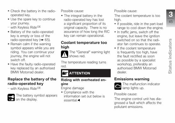
Check the battery in the radio-operated key.Use the spare key to continueyour journey.with Keyless Ride OE
Battery of the radio-operatedkey is empty or loss of theradio-operated key ( 65).Remain calm if the warningsymbol appears while you areriding. You can continue yourjourney, the engine will notswitch off.Have the faulty radio-operatedkey replaced by an authorisedBMW Motorrad dealer.
Replace the battery of theradio-operated key
with Keyless Ride OE
The battery symbol appearson the display.
Possible cause:The integral battery in theradio-operated key has losta significant proportion of itsoriginal capacity. There is noassurance of how long the R/Ckey can remain operational.
Coolant temperature toohigh
The "General" warning lightshows red.
The temperature reading turnsred.
ATTENTION
Riding with overheated en-gineEngine damage
Compliance with theinformation set out below isessential.
Possible cause:The coolant temperature is toohigh.
If possible, ride in the part-loadrange to cool down the engine.In traffic jams, switch off theengine, but leave the ignitionswitched on so that the radi-ator fan continues to operate.If the coolant temperatureis frequently too high, havethe fault rectified as soonas possible by a specialistworkshop, preferably anauthorised BMW Motorraddealer.
Emissions warningThe malfunction indicatorlamp lights up.
Possible cause:The engine control unit has dia-gnosed a fault which affects thepollutant emissions.
345
z Sta
tus
ind
ica
tors
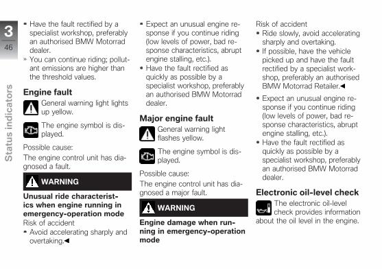
Have the fault rectified by aspecialist workshop, preferablyan authorised BMW Motorraddealer.You can continue riding; pollut-ant emissions are higher thanthe threshold values.
Engine faultGeneral warning light lightsup yellow.
The engine symbol is dis-played.
Possible cause:The engine control unit has dia-gnosed a fault.
WARNING
Unusual ride characterist-ics when engine running inemergency-operation modeRisk of accident
Avoid accelerating sharply andovertaking.
Expect an unusual engine re-sponse if you continue riding(low levels of power, bad re-sponse characteristics, abruptengine stalling, etc.).Have the fault rectified asquickly as possible by aspecialist workshop, preferablyan authorised BMW Motorraddealer.
Major engine faultGeneral warning lightflashes yellow.
The engine symbol is dis-played.
Possible cause:The engine control unit has dia-gnosed a major fault.
WARNING
Engine damage when run-ning in emergency-operationmode
Risk of accidentRide slowly, avoid acceleratingsharply and overtaking.If possible, have the vehiclepicked up and have the faultrectified by a specialist work-shop, preferably an authorisedBMW Motorrad Retailer.
Expect an unusual engine re-sponse if you continue riding(low levels of power, bad re-sponse characteristics, abruptengine stalling, etc.).Have the fault rectified asquickly as possible by aspecialist workshop, preferablyan authorised BMW Motorraddealer.
Electronic oil-level checkThe electronic oil-levelcheck provides information
about the oil level in the engine.
346
z Sta
tus
ind
ica
tors
The preconditions for the elec-tronic oil-level check are as fol-lows:
Engine at operating tempera-ture.Engine idling for at least tenseconds.No brake applied.Side stand retracted.Motorcycle standing upright.
The readings mean:
OK: oil level is correct.
CHECK!: check the oil level thenext time you stop for fuel.
– – –: oil level cannot be meas-ured (conditions as stated abovenot satisfied).
Engine-oil level too lowThe oil-can symbol appearson the display.
Possible cause:The electronic oil-level sensorhas registered an excessively lowoil level. Check the engine oillevel using the oil dipstick at thenext refuelling stop:
Check the engine oil level( 164).
If the oil level is too low:Top up the engine oil ( 165).
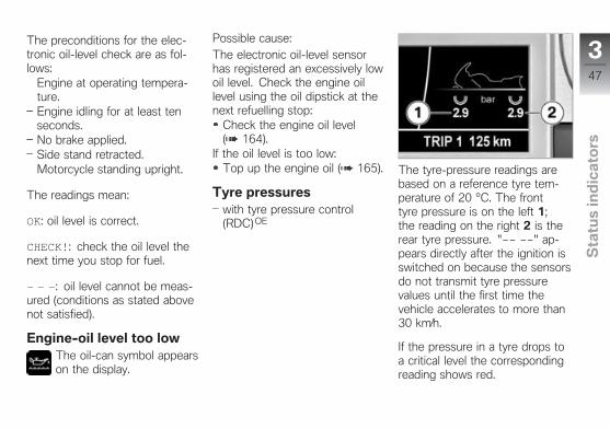
Tyre pressureswith tyre pressure control(RDC)OE
The tyre-pressure readings arebased on a reference tyre tem-perature of 20 °C. The fronttyre pressure is on the left 1;the reading on the right 2 is therear tyre pressure. " " ap-pears directly after the ignition isswitched on because the sensorsdo not transmit tyre pressurevalues until the first time thevehicle accelerates to more than30 km⁄h.
If the pressure in a tyre drops toa critical level the correspondingreading shows red.
347
z Sta
tus
ind
ica
tors
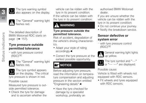
The tyre warning symbolalso appears on the display.
The "General" warning lightflashes red.
The detailed description ofBMW Motorrad RDC starts onpage ( 157).
Tyre pressure outsidepermitted tolerance
with tyre pressure control(RDC)OE
The "General" warning lightflashes red.
The tyre symbol appearson the display. The critical
tyre pressure is shown in red.
Possible cause:Measured tyre pressure is out-side permitted tolerance.
Check the tyre for damageand to ascertain whether the
vehicle can be ridden with thetyre in its present condition.
If the vehicle can be ridden withthe tyre in its present condition:
WARNING
Tyre pressure outside thepermitted tolerance.Risk of accident, degradation ofthe vehicle's driving characterist-ics.
Adapt your style of ridingaccordingly.
Correct the tyre pressure at theearliest possible opportunity.
NOTICE
Before adjusting tyre pressure,read the information on tempera-ture compensation and adjustingpressure in the section entitled"Engineering details".
Have the tyre checked fordamage by a specialistworkshop, preferably an
authorised BMW Motorraddealer.
If you are unsure whether thevehicle can be ridden with thetyre in its present condition:
Do not continue your journey.Notify the breakdown service.
Sensor defective orsystem error
with tyre pressure control(RDC)OE
General warning light lightsup yellow.
The tyre symbol and ""or " " are displayed.
Possible cause:Vehicle is fitted with wheels notequipped with RDC sensors.
Fit wheels and tyres equippedwith RDC sensors.
348
z Sta
tus
ind
ica
tors

Possible cause:One or two RDC sensors failed.
Have the fault rectified by aspecialist workshop, preferablyan authorised BMW Motorraddealer.
Possible cause:A system error has occurred.
Have the fault rectified by aspecialist workshop, preferablyan authorised BMW Motorraddealer.
Transmission faultwith tyre pressure control(RDC)OE
The tyre symbol and ""or " " are displayed.
Possible cause:The driving speed has not ac-celerated past the threshold ofapproximately 30 km/h. The RDCsensors do not start transmittingsignals until the vehicle reaches
a speed above this threshold forthe first time ( 157).
Observe the RDC display athigher speeds. A perman-ent fault is present only whenthe general warning light alsolights up. Under these circum-stances:Have the fault rectified by aspecialist workshop, preferablyan authorised BMW Motorraddealer.
Possible cause:Wireless communication with theRDC sensors has been disrupted.Possible causes include radio-communication systems operat-ing in the vicinity and interferingwith the link between the RDCcontrol unit and the sensors.
Move to another location andobserve the RDC readings. As-sume that a permanent faulthas not occurred unless the'General' warning light comes
on to accompany the symp-toms. Under these circum-stances:Have the fault rectified by aspecialist workshop, preferablyan authorised BMW Motorraddealer.
Battery of tyre-pressuresensor weak
with tyre pressure control(RDC)OE
General warning light lightsup yellow.
The RDC battery symbolappears on the display.
NOTICE
This error message shows brieflyonly after the Pre-Ride-Checkcompletes.
349
z Sta
tus
ind
ica
tors
Possible cause:The tyre pressure sensor batteryno longer provides its full capa-city. The tyre pressure monitor-ing function will be available for alimit time only.
Seek the advice of a specialistworkshop, preferably an author-ised BMW Motorrad dealer.
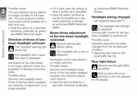
Direction of throw of low-beam headlight unknown
The "General" warning lightshows red.
The headlight with a ques-tion mark is displayed.
Illumination of the road aheadis no longer optimum; there is apossibility of dazzling oncomingtraffic.Possible cause:Direction and headlight beamthrow of the low-beam headlightare unknown, re-adjustment is nolonger possible.
If it is dark, park the vehicle orhave it picked up (if possible).Have the defect rectified asquickly as possible by a spe-cialist workshop, preferablyan authorised BMW Motorraddealer.
Beam-throw adjustmentof the low-beam headlightrestricted
General warning lightflashes yellow.
The headlight with a zero isdisplayed.
Illumination of the road ahead isno longer optimum.Possible cause:Direction and headlight beamthrow of the low-beam headlightprovides only restricted adjust-ment options.
Have the fault rectified by aspecialist workshop, preferably
an authorised BMW MotorradRetailer.
Headlight aiming changedwith adaptive head light OE
The headlight with left/rightis displayed.
Corning light control for the low-beam headlight is switched off.
Possible cause:Headlight alignment has beenchanged from the as-deliveredcondition.
Adjusting right-hand or left-hand traffic ( 72).
Rear light failureGeneral warning light lightsup yellow.
Bulb symbol with arrowpointing to the rear appears
on the display.
350
z Sta
tus
ind
ica
tors
Possible cause:Rear light, brake light or rearflashing turn indicator defective.The LED rear light must be re-placed.
Consult a specialist workshop,preferably an authorisedBMW Motorrad dealer.
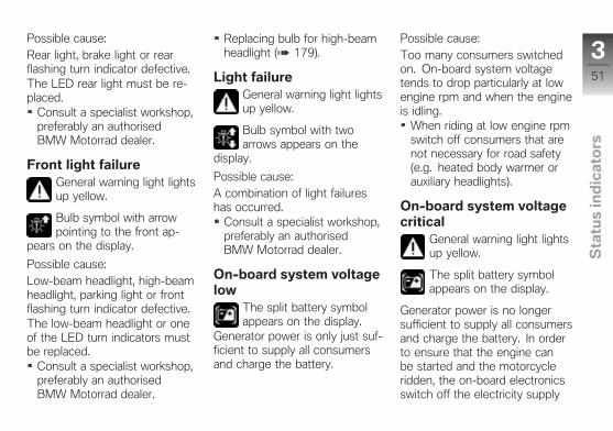
Front light failureGeneral warning light lightsup yellow.
Bulb symbol with arrowpointing to the front ap-
pears on the display.
Possible cause:Low-beam headlight, high-beamheadlight, parking light or frontflashing turn indicator defective.The low-beam headlight or oneof the LED turn indicators mustbe replaced.
Consult a specialist workshop,preferably an authorisedBMW Motorrad dealer.
Replacing bulb for high-beamheadlight ( 179).
Light failureGeneral warning light lightsup yellow.
Bulb symbol with twoarrows appears on the
display.
Possible cause:A combination of light failureshas occurred.
Consult a specialist workshop,preferably an authorisedBMW Motorrad dealer.
On-board system voltagelow
The split battery symbolappears on the display.
Generator power is only just suf-ficient to supply all consumersand charge the battery.
Possible cause:Too many consumers switchedon. On-board system voltagetends to drop particularly at lowengine rpm and when the engineis idling.
When riding at low engine rpmswitch off consumers that arenot necessary for road safety(e.g. heated body warmer orauxiliary headlights).
On-board system voltagecritical
General warning light lightsup yellow.
The split battery symbolappears on the display.
Generator power is no longersufficient to supply all consumersand charge the battery. In orderto ensure that the engine canbe started and the motorcycleridden, the on-board electronicsswitch off the electricity supply
351
z Sta
tus
ind
ica
tors
to the on-board sockets and theauxiliary headlights. In extremecases the seat heating and thegrip heating might also be shutdown.Possible cause:Too many consumers switchedon. On-board system voltagetends to drop particularly at lowengine rpm and when the engineis idling.
When riding at low engine rpmswitch off consumers that arenot necessary for road safety(e.g. heated body warmer orauxiliary headlights).
Insufficient battery chargecurrent
The "General" warning lightshows red.
The battery symbol appearson the display.
WARNING
Failure of the vehicle sys-temsRisk of accident
Do not continue your journey.
Battery is not being charged. Ifyou continue to ride the motor-cycle the on-board electronicswill drain the battery.Possible cause:Alternator or alternator drivefaulty.
Have the fault rectified asquickly as possible by aspecialist workshop, preferablyan authorised BMW Motorraddealer.
Anti-theft alarm batteryweak
with anti-theft alarm (DWA) OE
The alarm system batterysymbol appears on the
display.
NOTICE
This error message shows brieflyonly after the Pre-Ride-Checkcompletes.
Possible cause:The integral battery in the anti-theft alarm has lost a significantproportion of its original capacity.There is no assurance of howlong the anti-theft alarm can re-main operational if the vehicle'sbattery is disconnected.
Seek the advice of a specialistworkshop, preferably an author-ised BMW Motorrad dealer.
352
z Sta
tus
ind
ica
tors
Anti-theft alarm batteryflat
with anti-theft alarm (DWA) OE
General warning light lightsup yellow.
The alarm system batterysymbol appears on the
display.
NOTICE
This error message shows brieflyonly after the Pre-Ride-Checkcompletes.
Possible cause:The integral battery in the anti-theft alarm has lost its entire ori-ginal capacity. There is no as-surance that the anti-theft alarmwill be operational if the vehicle'sbattery is disconnected.
Seek the advice of a specialistworkshop, preferably an author-ised BMW Motorrad dealer.
Central locking lockedwith central locking systemOE
The locked symbol appearson the display.
All locks in the central lockingsystem are locked.
ABS self-diagnosis notcompleted
The ABS indicator andwarning light flashes.
Possible cause:Self-diagnosis did not complete,so the ABS function is not avail-able. The motorcycle must reacha speed of at least 5 km/h inorder for ABS self-diagnosis tocomplete.
Pull away slowly. Bear in mindthat the ABS function is notavailable until self-diagnosis hascompleted.
ABS faultThe ABS indicator andwarning light shows.
Possible cause:The ABS control unit has detec-ted a fault. The ABS function isnot available.
You can continue to ride thevehicle, but make due provi-sion for the fact that the ABSfunction is not available. Bearin mind the more detailed in-formation on situations that canlead to an ABS fault ( 152).Have the fault rectified asquickly as possible by aspecialist workshop, preferablyan authorised BMW Motorraddealer.
DTC interventionThe DTC indicator lightflashes quickly.
The DTC has detected a degreeof instability at the rear wheel
353
z Sta
tus
ind
ica
tors
and has intervened to reducetorque. The indicator lightflashes for longer than the DTCintervention lasts. This affordsthe rider visual feedback oncontrol intervention even after thecritical situation has been dealtwith.
DTC self-diagnosis notcompleted
The DTC indicator lightflashes slowly.
Possible cause:Self-diagnosis did not complete,so the DTC function is not avail-able. The engine must be run-ning and the motorcycle mustreach a minimum speed of 5km⁄h to complete DTC self-dia-gnosis..
Pull away slowly. Bear in mindthat the DTC function is notavailable until self-diagnosis hascompleted.
DTC switched offThe DTC indicator lightlights up.
Possible cause:The rider has switched off theDTC system.
Switch on DTC.
DTC faultThe DTC indicator lightlights up.
Possible cause:The DTC control unit has detec-ted a fault. The DTC function isnot available.
You can continue to ride. Bearin mind that the DTC functionis not available. Bear in mindthe more detailed informationon situations that can lead to aDTC fault ( 154).Have the fault rectified asquickly as possible by aspecialist workshop, preferably
an authorised BMW Motorraddealer.
DESA faultGeneral warning light lightsup yellow.
The symbol for DESA faultis displayed.
Possible cause:The DESA control unit has de-tected a fault. In this condition,the motorcycle has too muchdamping and is uncomfortable todrive, especially on roads in poorcondition.
Have the fault rectified asquickly as possible by aspecialist workshop, preferablyan authorised BMW Motorraddealer.
RangeThe range readout indic-ates how far you can ride
with the fuel remaining in the
354
z Sta
tus
ind
ica
tors
tank. The figure for average con-sumption used to calculate rangeis not shown and might not bethe same as the average-con-sumption reading that appears onthe display.You must put at least five litres offuel into the fuel tank for the newlevel to be registered correctly.If the sensor cannot register thenew level the range readout can-not be updated.When the motorcycle is proppedon its side stand the slight angleof inclination means that thesensor cannot register the fuellevel correctly. This is the reasonwhy the range is calculated onlywhen the side stand is in the re-tracted position.
NOTICE
The calculated range is onlyan approximate figure. Con-sequently, BMW Motorrad re-commends that you should not
try to use the full range beforerefuelling.
Fuel down to reserveThe reserve-fuel symbollights up.
The fuel-level reading turns yel-low.
WARNING
Irregular engine operation orengine shutdown due to lackof fuelRisk of accident, damage to cata-lytic converter
Do not run the fuel tank dry.
Possible cause:The fuel tank contains no morethan the reserve quantity of fuel.
Reserve fuel
approx. 4 l
Refuelling ( 143).
Hill Start Control Proactive
Green holding symbol isdisplayed.
Possible cause:Hill Start Control Pro ( 159)has been activated automaticallyor activated by the rider.
Operate Hill Start Control Pro( 91).Switching automatic Hill StartControl Pro on and off ( 92).
Hill Start Control Proactive
White holding symbol isdisplayed.
Possible cause:The automatic Hill Start ControlPro is active. If the motorcyclestops on an incline of > 5%, themotorcycle is automatically heldin place by the brakes.
355
z Sta
tus
ind
ica
tors
Switching automatic Hill StartControl Pro on and off ( 92).
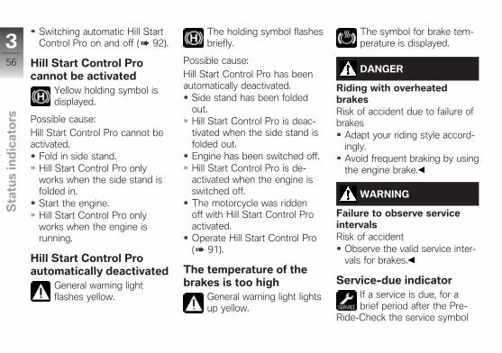
Hill Start Control Procannot be activated
Yellow holding symbol isdisplayed.
Possible cause:Hill Start Control Pro cannot beactivated.
Fold in side stand.Hill Start Control Pro onlyworks when the side stand isfolded in.Start the engine.Hill Start Control Pro onlyworks when the engine isrunning.
Hill Start Control Proautomatically deactivated
General warning lightflashes yellow.
The holding symbol flashesbriefly.
Possible cause:Hill Start Control Pro has beenautomatically deactivated.
Side stand has been foldedout.Hill Start Control Pro is deac-tivated when the side stand isfolded out.Engine has been switched off.Hill Start Control Pro is de-activated when the engine isswitched off.The motorcycle was riddenoff with Hill Start Control Proactivated.Operate Hill Start Control Pro( 91).
The temperature of thebrakes is too high
General warning light lightsup yellow.
The symbol for brake tem-perature is displayed.
DANGER
Riding with overheatedbrakesRisk of accident due to failure ofbrakes
Adapt your riding style accord-ingly.Avoid frequent braking by usingthe engine brake.
WARNING
Failure to observe serviceintervalsRisk of accident
Observe the valid service inter-vals for brakes.
Service-due indicatorIf a service is due, for abrief period after the Pre-
Ride-Check the service symbol
356
z Sta
tus
ind
ica
tors
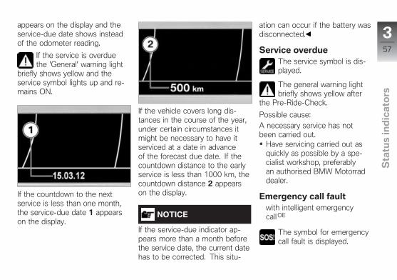
appears on the display and theservice-due date shows insteadof the odometer reading.
If the service is overduethe 'General' warning light
briefly shows yellow and theservice symbol lights up and re-mains ON.
If the countdown to the nextservice is less than one month,the service-due date 1 appearson the display.
If the vehicle covers long dis-tances in the course of the year,under certain circumstances itmight be necessary to have itserviced at a date in advanceof the forecast due date. If thecountdown distance to the earlyservice is less than 1000 km, thecountdown distance 2 appearson the display.
NOTICE
If the service-due indicator ap-pears more than a month beforethe service date, the current datehas to be corrected. This situ-
ation can occur if the battery wasdisconnected.
Service overdueThe service symbol is dis-played.
The general warning lightbriefly shows yellow after
the Pre-Ride-Check.
Possible cause:A necessary service has notbeen carried out.
Have servicing carried out asquickly as possible by a spe-cialist workshop, preferablyan authorised BMW Motorraddealer.
Emergency call faultwith intelligent emergencycall OE
The symbol for emergencycall fault is displayed.
357
z Sta
tus
ind
ica
tors
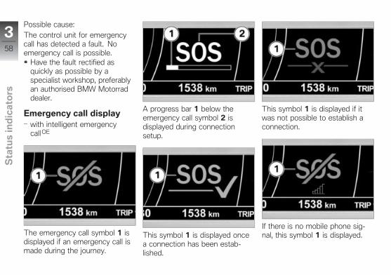
Possible cause:The control unit for emergencycall has detected a fault. Noemergency call is possible.
Have the fault rectified asquickly as possible by aspecialist workshop, preferablyan authorised BMW Motorraddealer.
Emergency call displaywith intelligent emergencycall OE
The emergency call symbol 1 isdisplayed if an emergency call ismade during the journey.
A progress bar 1 below theemergency call symbol 2 isdisplayed during connectionsetup.
This symbol 1 is displayed oncea connection has been estab-lished.
This symbol 1 is displayed if itwas not possible to establish aconnection.
If there is no mobile phone sig-nal, this symbol 1 is displayed.
358
z Sta
tus
ind
ica
tors
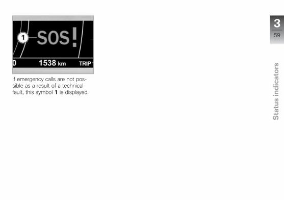
If emergency calls are not pos-sible as a result of a technicalfault, this symbol 1 is displayed.
359
z Sta
tus
ind
ica
tors

360
z Sta
tus
ind
ica
tors

Operation
Ignition switch/steering lock . . . . . . . . . 62
Ignition . . . . . . . . . . . . . . . . . . . . . . . . . . . . . . 62
Ignition with Keyless Ride . . . . . . . . . . . 63
Electronic immobiliser EWS. . . . . . . . . 66
Emergency off switch (killswitch) . . . . . . . . . . . . . . . . . . . . . . . . . . . . . . 67
Intelligent emergency call . . . . . . . . . . . 68
Reverser . . . . . . . . . . . . . . . . . . . . . . . . . . . . 70
Lights . . . . . . . . . . . . . . . . . . . . . . . . . . . . . . . 71
Daytime riding light . . . . . . . . . . . . . . . . . 74
Hazard warning lights . . . . . . . . . . . . . . . 75
Turn indicators . . . . . . . . . . . . . . . . . . . . . . 76
Multifunction display . . . . . . . . . . . . . . . . 76
On-board computer . . . . . . . . . . . . . . . . . 81
Trip recorder . . . . . . . . . . . . . . . . . . . . . . . . 82
Anti-theft alarm (DWA) . . . . . . . . . . . . . . 83
Dynamic Traction Control (DTC) . . . . 87
Electronic Suspension Adjustment(DESA) . . . . . . . . . . . . . . . . . . . . . . . . . . . . . 87
Riding mode . . . . . . . . . . . . . . . . . . . . . . . . 88
Cruise-control system . . . . . . . . . . . . . . 89
Hill Start Control . . . . . . . . . . . . . . . . . . . . 91
Central locking system . . . . . . . . . . . . . . 92
Grip heating. . . . . . . . . . . . . . . . . . . . . . . . . 96
Seat heating . . . . . . . . . . . . . . . . . . . . . . . . 97
Seat . . . . . . . . . . . . . . . . . . . . . . . . . . . . . . . . 98
Storage compartments . . . . . . . . . . . . . 99
461
z Op
era
tio
n
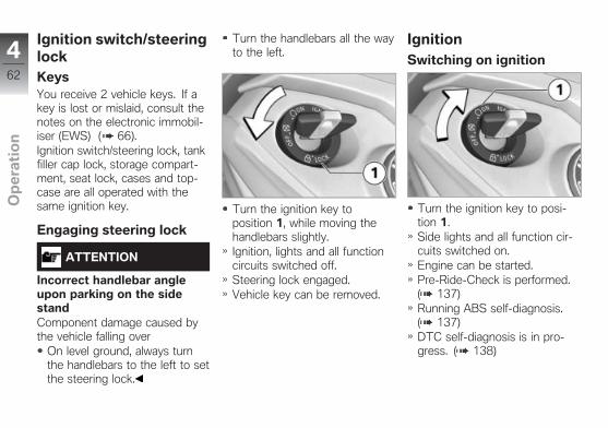
Ignition switch/steeringlockKeysYou receive 2 vehicle keys. If akey is lost or mislaid, consult thenotes on the electronic immobil-iser (EWS) ( 66).Ignition switch/steering lock, tankfiller cap lock, storage compart-ment, seat lock, cases and top-case are all operated with thesame ignition key.
Engaging steering lock
ATTENTION
Incorrect handlebar angleupon parking on the sidestandComponent damage caused bythe vehicle falling over
On level ground, always turnthe handlebars to the left to setthe steering lock.
Turn the handlebars all the wayto the left.
Turn the ignition key toposition 1, while moving thehandlebars slightly.Ignition, lights and all functioncircuits switched off.Steering lock engaged.Vehicle key can be removed.
IgnitionSwitching on ignition
Turn the ignition key to posi-tion 1.Side lights and all function cir-cuits switched on.Engine can be started.Pre-Ride-Check is performed.( 137)Running ABS self-diagnosis.( 137)DTC self-diagnosis is in pro-gress. ( 138)
462
z Op
era
tio
n
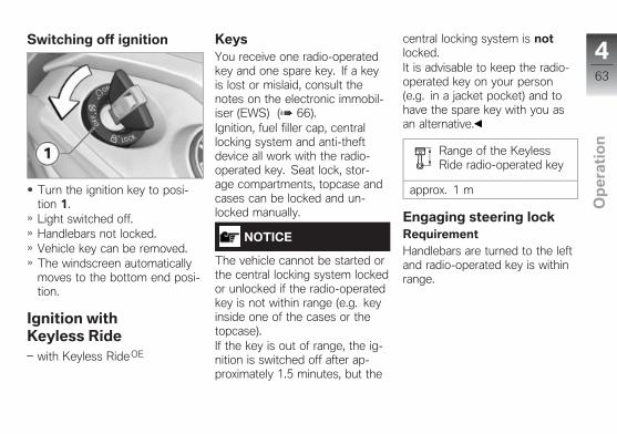
Switching off ignition
Turn the ignition key to posi-tion 1.Light switched off.Handlebars not locked.Vehicle key can be removed.The windscreen automaticallymoves to the bottom end posi-tion.
Ignition withKeyless Ride
with Keyless Ride OE
KeysYou receive one radio-operatedkey and one spare key. If a keyis lost or mislaid, consult thenotes on the electronic immobil-iser (EWS) ( 66).Ignition, fuel filler cap, centrallocking system and anti-theftdevice all work with the radio-operated key. Seat lock, stor-age compartments, topcase andcases can be locked and un-locked manually.
NOTICE
The vehicle cannot be started orthe central locking system lockedor unlocked if the radio-operatedkey is not within range (e.g. keyinside one of the cases or thetopcase).If the key is out of range, the ig-nition is switched off after ap-proximately 1.5 minutes, but the
central locking system is notlocked.It is advisable to keep the radio-operated key on your person(e.g. in a jacket pocket) and tohave the spare key with you asan alternative.
Range of the KeylessRide radio-operated key
approx. 1 m
Engaging steering lockRequirementHandlebars are turned to the leftand radio-operated key is withinrange.
463
z Op
era
tio
n
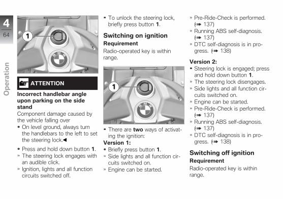
ATTENTION
Incorrect handlebar angleupon parking on the sidestandComponent damage caused bythe vehicle falling over
On level ground, always turnthe handlebars to the left to setthe steering lock.
Press and hold down button 1.The steering lock engages withan audible click.Ignition, lights and all functioncircuits switched off.
To unlock the steering lock,briefly press button 1.
Switching on ignitionRequirementRadio-operated key is withinrange.
There are two ways of activat-ing the ignition:
Version 1:Briefly press button 1.Side lights and all function cir-cuits switched on.Engine can be started.
Pre-Ride-Check is performed.( 137)Running ABS self-diagnosis.( 137)DTC self-diagnosis is in pro-gress. ( 138)
Version 2:Steering lock is engaged; pressand hold down button 1.The steering lock disengages.Side lights and all function cir-cuits switched on.Engine can be started.Pre-Ride-Check is performed.( 137)Running ABS self-diagnosis.( 137)DTC self-diagnosis is in pro-gress. ( 138)
Switching off ignitionRequirementRadio-operated key is withinrange.
464
z Op
era
tio
n
There are two ways of deactiv-ating the ignition:
Version 1:Briefly press button 1.Light is switched off.Handlebars (steering lock) arenot locked.The windscreen automaticallymoves to the bottom end posi-tion.
Version 2:Turn the handlebars all the wayto the left.Press and hold down button 1.Light is switched off.The steering lock engages.The windscreen automaticallymoves to the bottom end posi-tion.
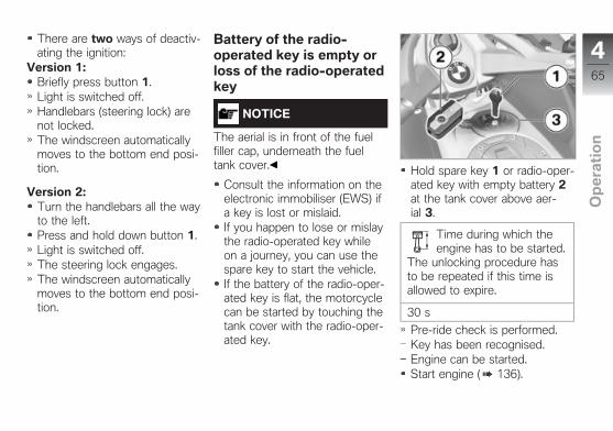
Battery of the radio-operated key is empty orloss of the radio-operatedkey
NOTICE
The aerial is in front of the fuelfiller cap, underneath the fueltank cover.
Consult the information on theelectronic immobiliser (EWS) ifa key is lost or mislaid.If you happen to lose or mislaythe radio-operated key whileon a journey, you can use thespare key to start the vehicle.If the battery of the radio-oper-ated key is flat, the motorcyclecan be started by touching thetank cover with the radio-oper-ated key.
Hold spare key 1 or radio-oper-ated key with empty battery 2at the tank cover above aer-ial 3.
Time during which theengine has to be started.
The unlocking procedure hasto be repeated if this time isallowed to expire.
30 s
Pre-ride check is performed.Key has been recognised.Engine can be started.Start engine ( 136).
465
z Op
era
tio
n

Replace the battery of theradio-operated keyIf the radio-operated key doesnot react when you short-pressor long-press a button:
The battery in the radio-oper-ated key is not at full capacity.Change the battery.
The battery symbol appearson the display.
Press button 1.Key bit flips out.Lever out the battery lid 2 onthe recess for the key bit.
Remove the battery lid 2 andseal 3.Remove battery 4.Dispose of the old battery inaccordance with all applicablelaws and regulations; do notattempt to dispose of batteriesas domestic waste.
ATTENTION
Unsuitable or incorrectly in-serted batteriesComponent damage
Use a battery compliant withthe manufacturer's specifica-tions.When inserting the battery,always make sure polarity iscorrect.
Insert the new battery with thepositive terminal up.
Battery type
For Keyless Ride radio-oper-ated key
CR 2032
Install the seal 3 and batterylid 2.Red LED on the instrumentpanel flashes.The remote control is againready for use.
Electronic immobiliserEWSThe on-board electronics accessthe data saved in the vehicle keyvia a ring aerial in the R/C ignitionlock. The ignition is not enabledfor starting until the engine con-trol unit has recognised the igni-tion key as "authorised" for yourmotorcycle.
466
z Op
era
tio
n
NOTICE
Another vehicle key attached tothe same ring as the vehicle keyused to start the engine could"irritate" the electronics, in whichcase the enabling signal for start-ing is not issued. The warningwith the key symbol appears inthe multifunction display.Always keep other vehicle keysseparate from the vehicle keyused to start the engine.
If you lose your key, youcan have it barred by yourBMW Motorrad authoriseddealer. If you wish to do this, youwill need to bring all other keysfor the motorcycle with you.The engine cannot be startedby a barred ignition key, but anignition key that has been barredcan subsequently be reactivated.You can obtain spare/extra keysonly through an authorised
BMW Motorrad dealer. Theignition keys are part of anintegrated security system, sothe dealer is under an obligationto check the legitimacy of allapplications for replacement/extrakeys.
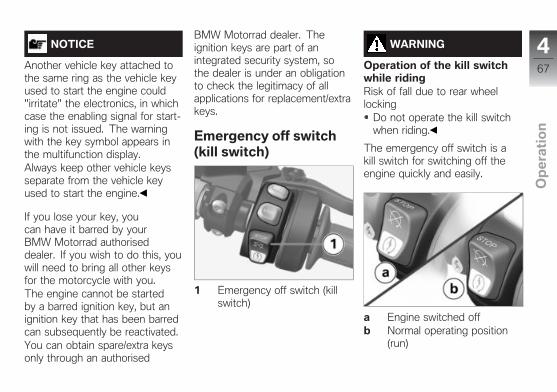
Emergency off switch(kill switch)
1 Emergency off switch (killswitch)
WARNING
Operation of the kill switchwhile ridingRisk of fall due to rear wheellocking
Do not operate the kill switchwhen riding.
The emergency off switch is akill switch for switching off theengine quickly and easily.
a Engine switched offb Normal operating position
(run)
467
z Op
era
tio
n
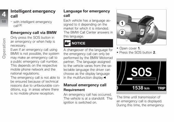
Intelligent emergencycall
with intelligent emergencycall OE
Emergency call via BMWOnly press the SOS button inan emergency or when help isnecessary.Even if an emergency call usingBMW is not possible, the systemmay make an emergency call toa public emergency call number.This depends on the respectivemobile phone network and thenational regulations.The emergency call is not able tobe ensured because of technicalreasons due to unfavourable con-ditions, e.g. in areas where thereis no mobile phone reception.
Language for emergencycallEach vehicle has a language as-signed to it depending on themarket for which it is intended.The BMW Call Center answers inthis language.
NOTICE
A changeover of the language forthe emergency call can only beperformed by the BMW Motorradpartner. The language assignedto the vehicle varies from the se-lectable language the driver canchoose as the display languagein the multifunction display.
Manual emergency callRequirementAn emergency call has occurred.The vehicle is at a standstill. Theignition is switched on.
Open cover 1.Press the SOS button 2.
The time until transmission ofan emergency call is displayed.During this time, the emergency
468
z Op
era
tio
n

call can be cancelled by pressingand holding the SOS button.
Operate the emergency-offswitch to stop the engine.Remove helmet.After expiry of the timer, avoice contact to the BMW CallCenter is established.
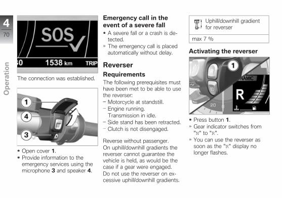
The connection was established.
Provide information to theemergency services using themicrophone 3 and speaker 4.
Automatic emergency callThe intelligent emergency callis active after the ignition isswitched on and reacts if a fall orcrash occurs.
Emergency call in theevent of a light fall
A light fall or a crash was de-tected.An acoustic signal is sounded.
The time until transmission ofan emergency call is displayed.During this time, the emergencycall can be cancelled by pressingand holding the SOS button.
If possible, remove helmet andstop engine.After expiry of the timer, avoice contact to the BMW CallCenter is established.
469
z Op
era
tio
n
The connection was established.
Open cover 1.Provide information to theemergency services using themicrophone 3 and speaker 4.
Emergency call in theevent of a severe fall
A severe fall or a crash is de-tected.The emergency call is placedautomatically without delay.
ReverserRequirementsThe following prerequisites musthave been met to be able to usethe reverser:
Motorcycle at standstill.Engine running.Transmission in idle.Side stand has been retracted.Clutch is not disengaged.
Reverse without passenger.On uphill/downhill gradients thereverser cannot guarantee thevehicle is held, as would be thecase if a gear were engaged.Do not use the reverser on ex-cessive uphill/downhill gradients.
Uphill/downhill gradientfor reverser
max 7 %
Activating the reverser
Press button 1.Gear indicator switches from"N" to "R".You can use the reverser assoon as the "R" display nolonger flashes.
470
z Op
era
tio
n
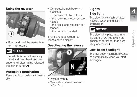
Using the reverser
Press and hold the starter but-ton 1 to reverse.
NOTICE
The vehicle is not automaticallybraked and may therefore con-tinue to roll after having releasedthe starter button.
Automatic terminationReversing is cancelled automatic-ally:
On excessive uphill/downhillgradientsIn the event of obstructionsIf the reversing motor has over-heatedIf the side stand has been ex-tendedIf the brake is operated
If reversing is cancelled, "R"flashes on the display.
Deactivating the reverser
Press button 1.Gear indicator switches from"R" to "N".
LightsSide lightThe side lights switch on auto-matically when the ignition isswitched on.
NOTICE
The side lights place a strain onthe battery. Do not switch theignition on for longer than abso-lutely necessary.
Low-beam headlightThe low-beam headlight switcheson automatically when you startthe engine.
471
z Op
era
tio
n
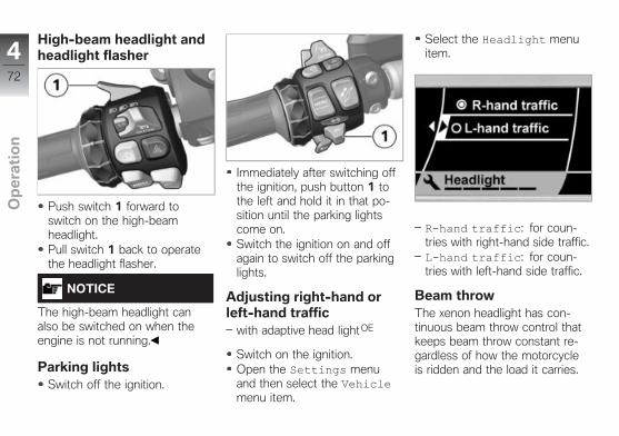
High-beam headlight andheadlight flasher
Push switch 1 forward toswitch on the high-beamheadlight.Pull switch 1 back to operatethe headlight flasher.
NOTICE
The high-beam headlight canalso be switched on when theengine is not running.
Parking lightsSwitch off the ignition.
Immediately after switching offthe ignition, push button 1 tothe left and hold it in that po-sition until the parking lightscome on.Switch the ignition on and offagain to switch off the parkinglights.
Adjusting right-hand orleft-hand traffic
with adaptive head light OE
Switch on the ignition.Open the Settings menuand then select the Vehiclemenu item.
Select the Headlight menuitem.
Rhand traffic: for coun-tries with right-hand side traffic.Lhand traffic: for coun-tries with left-hand side traffic.
Beam throwThe xenon headlight has con-tinuous beam throw control thatkeeps beam throw constant re-gardless of how the motorcycleis ridden and the load it carries.
472
z Op
era
tio
n
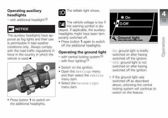
Operating auxiliaryheadlights
with additional headlightOE
NOTICE
The auxiliary headlights have ap-proval as fog lights and their useis permissible in bad weatherconditions only. Always complywith the road traffic regulations inforce in the country in which thevehicle is used.
Press button 1 to switch onthe additional headlights.
The telltale light shows.
The vehicle voltage is low ifthis warning symbol is dis-
played. If applicable, the auxiliaryheadlights might have been tem-porarily switched off.
Press button 1 again to switchoff the additional headlights.
Operating the ground lightwith central locking systemOE
with floor lightingOA
Switch on the ignition.Open the Settings menuand then select the Vehiclemenu item.Select the Ground lightmenu item.
On: ground light is brieflyswitched on after havingswitched off the ignition.Off: ground light is notswitched on after havingswitched off the ignition.
If the ground light wasswitched off as describedabove, unlocking the centrallocking system will continue toswitch on the feature.
473
z Op
era
tio
n
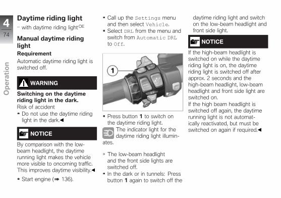
Daytime riding lightwith daytime riding light OE
Manual daytime ridinglightRequirementAutomatic daytime riding light isswitched off.
WARNING
Switching on the daytimeriding light in the dark.Risk of accident
Do not use the daytime ridinglight in the dark.
NOTICE
By comparison with the low-beam headlight, the daytimerunning light makes the vehiclemore visible to oncoming traffic.This improves daytime visibility.
Start engine ( 136).
Call up the Settings menuand then select Vehicle.Select DRL from the menu andswitch from Automatic DRLto Off.
Press button 1 to switch onthe daytime riding light.
The indicator light for thedaytime riding light illumin-
ates.
The low-beam headlightand the front side lights areswitched off.In the dark or in tunnels: Pressbutton 1 again to switch off the
daytime riding light and switchon the low-beam headlight andfront side light.
NOTICE
If the high-beam headlight isswitched on while the daytimeriding light is on, the daytimeriding light is switched off afterapprox. 2 seconds and thehigh-beam headlight, low-beamheadlight and front side light areswitched on.If the high beam headlight isswitched off again, the daytimerunning light is not automat-ically reactivated, but must beswitched on again if required.
474
z Op
era
tio
n
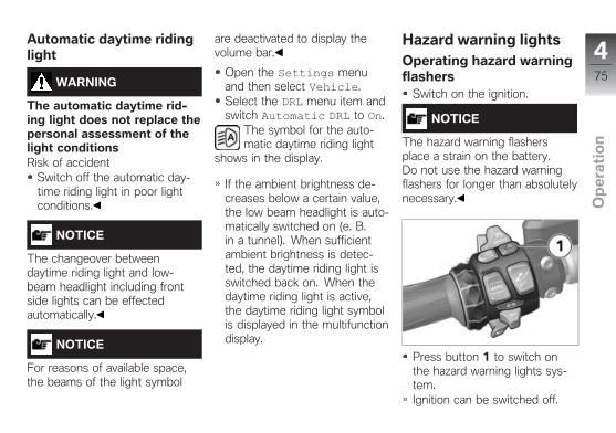
Automatic daytime ridinglight
WARNING
The automatic daytime rid-ing light does not replace thepersonal assessment of thelight conditionsRisk of accident
Switch off the automatic day-time riding light in poor lightconditions.
NOTICE
The changeover betweendaytime riding light and low-beam headlight including frontside lights can be effectedautomatically.
NOTICE
For reasons of available space,the beams of the light symbol
are deactivated to display thevolume bar.
Open the Settings menuand then select Vehicle.Select the DRL menu item andswitch Automatic DRL to On.
The symbol for the auto-matic daytime riding light
shows in the display.
If the ambient brightness de-creases below a certain value,the low beam headlight is auto-matically switched on (e. B.in a tunnel). When sufficientambient brightness is detec-ted, the daytime riding light isswitched back on. When thedaytime riding light is active,the daytime riding light symbolis displayed in the multifunctiondisplay.
Hazard warning lightsOperating hazard warningflashers
Switch on the ignition.
NOTICE
The hazard warning flashersplace a strain on the battery.Do not use the hazard warningflashers for longer than absolutelynecessary.
Press button 1 to switch onthe hazard warning lights sys-tem.Ignition can be switched off.
475
z Op
era
tio
n
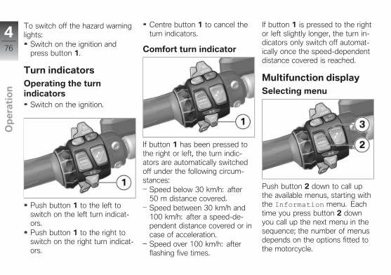
To switch off the hazard warninglights:
Switch on the ignition andpress button 1.
Turn indicatorsOperating the turnindicators
Switch on the ignition.
Push button 1 to the left toswitch on the left turn indicat-ors.Push button 1 to the right toswitch on the right turn indicat-ors.
Centre button 1 to cancel theturn indicators.
Comfort turn indicator
If button 1 has been pressed tothe right or left, the turn indic-ators are automatically switchedoff under the following circum-stances:
Speed below 30 km/h: after50 m distance covered.Speed between 30 km/h and100 km/h: after a speed-de-pendent distance covered or incase of acceleration.Speed over 100 km/h: afterflashing five times.
If button 1 is pressed to the rightor left slightly longer, the turn in-dicators only switch off automat-ically once the speed-dependentdistance covered is reached.
Multifunction displaySelecting menu
Push button 2 down to call upthe available menus, starting withthe Information menu. Eachtime you press button 2 downyou call up the next menu in thesequence; the number of menusdepends on the options fitted tothe motorcycle.
476
z Op
era
tio
n
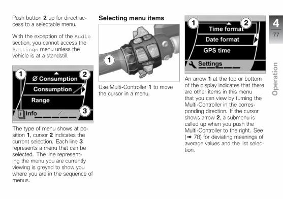
Push button 2 up for direct ac-cess to a selectable menu.
With the exception of the Audiosection, you cannot access theSettings menu unless thevehicle is at a standstill.
The type of menu shows at po-sition 1, cursor 2 indicates thecurrent selection. Each line 3represents a menu that can beselected. The line represent-ing the menu you are currentlyviewing is greyed to show youwhere you are in the sequence ofmenus.
Selecting menu items
Use Multi-Controller 1 to movethe cursor in a menu.
An arrow 1 at the top or bottomof the display indicates that thereare other items in this menuthat you can view by turning theMulti-Controller in the corres-ponding direction. If the cursorshows arrow 2, a submenu iscalled up when you push theMulti-Controller to the right. See( 78) for deviating meanings ofaverage values and the list selec-tion.
477
z Op
era
tio
n
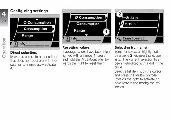
Configuring settings
Direct selection:Move the cursor to a menu itemthat does not require any furthersettings to immediately activateit.
Resetting values:If average values have been high-lighted with an arrow 1, pressand hold the Multi-Controller to-wards the right to reset them.
Selecting from a list:Items for selection highlightedby a circle 2 represent selectionlists. The current selection hasbeen highlighted with a dot in thecircle.Select a list item with the cursorand press the Multi-Controllertowards the right to activate ordeactivate it and modify the se-lection.
478
z Op
era
tio
n
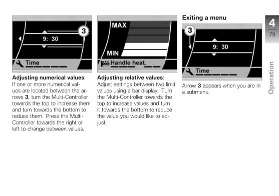
Adjusting numerical values:If one or more numerical val-ues are located between the ar-rows 3, turn the Multi-Controllertowards the top to increase themand turn towards the bottom toreduce them. Press the Multi-Controller towards the right orleft to change between values.
Adjusting relative values:Adjust settings between two limitvalues using a bar display. Turnthe Multi-Controller towards thetop to increase values and turnit towards the bottom to reducethe value you would like to ad-just.
Exiting a menu
Arrow 3 appears when you are ina submenu.
479
z Op
era
tio
n
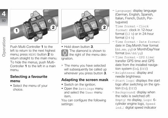
Push Multi-Controller 1 to theleft to return to the next highestmenu; press MENU button 2 toreturn straight to the main menu.To hide the menus, push Multi-Controller 1 to the left in a mainmenu.
Selecting a favouritemenu
Select the menu of yourchoice.
Hold down button 3.The diamond is shown tothe right of the menu des-
ignation.
The menu you have selectedwill subsequently be called upwhenever you press button 3.
Adapting the screen maskSwitch on the ignition.Open the Settings menuand select the User menuitem.
You can configure the followingsettings:
Language: display language(German, English, Spanish,Italian, French, Dutch, Por-tuguese)Time format - Clockformat: clock in 12-hourformat (12 h) or in 24-hourformat (24 h)Time format - Date format:date in Day.Month.Year format(dd.mm.yy) or Month/Day/Yearformat (mm/dd/yy)Time format - GPS time:transfer GPS time and GPSdate from the installed naviga-tion system (On), (Off)Brightness: display andneedle brightnessStart logo: displays the startlogo after switching on the igni-tion (On), (Off)Background: display whenthe radio is switched off:Empty: no display, Logo: 6-cylinder engine logo, Speedind.: digital speed indicator
480
z Op
era
tio
n

Default status: restorefactory conditions (if Reset!is displayed, press and hold theMulti-Controller towards theright)Configure the desired settingsusing the Multi-Controller.
On-board computerSelect display
Open the Info menu and thenselect the desired information.
The following information may bedisplayed in this area 3:
Ø consumption: average con-sumptionConsumption: current con-sumptionRange: range with remainingfuelØ speed: average speedTemperature: ambient tem-peratureTyre pressure: tyre pres-suresStopwatch: stopwatchTrav. times: travelling timesDate: current dateVeh. voltage: vehiclevoltageOil level: engine oil levelOff: no display
Resetting the averagevalues
Open the Information menuand then select the averagevalue you would like to reset.
Press and hold the Multi-Con-troller towards the right untilthe average value is reset.
Operating the stopwatchCall up the Info menu andselect Stopwatch.
With the stopwatch stopped,push Multi-Controller 1 to theright to start the stopwatch.The stopwatch continues tim-ing even if you select someother reading or switch off theignition.
481
z Op
era
tio
n
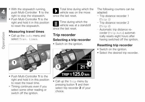
With the stopwatch running,push Multi-Controller 1 to theright to stop the stopwatch.Push Multi-Controller 1 to theright and hold it in this positionto reset the stopwatch.
Measuring travel timesCall up the Info menu andselect Trav. times.
Push Multi-Controller 1 to theright and hold it in this positionto reset the travel time.Timing continues even if youselect some other reading orswitch off the ignition.
Total time during which thevehicle was on the move
since the last reset.
Time during which thevehicle was at a standstill
since the last reset.
Trip recorderSelecting a trip recorder
Switch on the ignition.
Call up the Trip menu bypressing button 1 and thenselect trip recorder 2 of yourchoice.
The following counters can beadapted:
Trip distance recorder 1(Trip 1)Trip distance recorder 2(Trip 2)Automatic trip distance re-corder (Trip Auto) automat-ically resets eight hours afterhaving switched off the ignition.
Resetting trip recorderSwitch on the ignition.Select the desired trip recorder.
482
z Op
era
tio
n
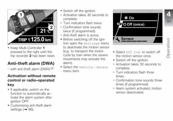
Keep Multi-Controller 1pressed to the right until thetrip recorder 2 has been reset.
Anti-theft alarm (DWA)with anti-theft alarm (DWA) OE
Activation without remotecontrol or radio-operatedkey
If applicable, switch on thefunction to automatically ac-tivate the alarm system afterignition OFF.Customising anti-theft alarmsettings ( 86).
Switch off the ignition.Activation takes 30 seconds tocomplete.Turn indicators flash twice.Confirmation tone soundstwice (if programmed).Anti-theft alarm is active.Before switching off the igni-tion open the Settings menuto deactivate the motion sensor(e.g. to transport the motor-cycle by train when the severemovements may activate thealarm).Select the Vehicle - Sensormenu item.
Select Off (1x) to switch offthe motion sensor once.Switch off the ignition.Activation takes 30 seconds tocomplete.Turn indicators flash threetimes.Confirmation tone sounds threetimes (if programmed).Alarm system activated, motionsensor deactivated.
483
z Op
era
tio
n
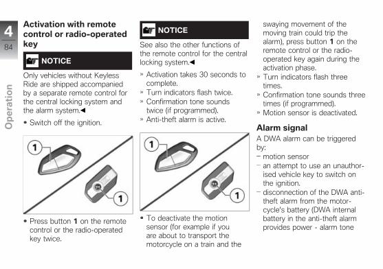
Activation with remotecontrol or radio-operatedkey
NOTICE
Only vehicles without KeylessRide are shipped accompaniedby a separate remote control forthe central locking system andthe alarm system.
Switch off the ignition.
Press button 1 on the remotecontrol or the radio-operatedkey twice.
NOTICE
See also the other functions ofthe remote control for the centrallocking system.
Activation takes 30 seconds tocomplete.Turn indicators flash twice.Confirmation tone soundstwice (if programmed).Anti-theft alarm is active.
To deactivate the motionsensor (for example if youare about to transport themotorcycle on a train and the
swaying movement of themoving train could trip thealarm), press button 1 on theremote control or the radio-operated key again during theactivation phase.Turn indicators flash threetimes.Confirmation tone sounds threetimes (if programmed).Motion sensor is deactivated.
Alarm signalA DWA alarm can be triggeredby:
motion sensoran attempt to use an unauthor-ised vehicle key to switch onthe ignition.disconnection of the DWA anti-theft alarm from the motor-cycle's battery (DWA internalbattery in the anti-theft alarmprovides power - alarm tone
484
z Op
era
tio
n

only, the turn indicators do notflash).
All functions are sustained evenif the internal battery of the DWAanti-theft alarm system is flat; theonly difference is that an alarmcannot be triggered if the systemis disconnected from the motor-cycle's battery.
An alarm lasts for approximately26 seconds. While an alarm is inprogress an alarm tone soundsand the turn indicators flash. Youcan adjust the alarm tone type inthe multifunction display.
An activated alarm can be can-celled at any time by pressingthe 2 button of the remote con-trol or the radio-operated keywithout deactivating the DWA.
If an alarm was activated whilethe motorcycle was unattended,the rider is notified accordinglyby an alarm tone sounding oncewhen the ignition is switched on.The DWA LED then indicatesthe reason for the alarm for oneminute.
Light signals issued by theDWA LED:
Flashes 1x: Motion sensor 1Flashes 2x: Motion sensor 2Flashes 3x: Ignition switchedon with unauthorised vehiclekeyFlashes 4x: Disconnection ofthe anti-theft alarm from themotorcycle's batteryFlashes 5x: Motion sensor 3
Deactivation withoutremote control or radio-operated key
Kill switch in operating position(run).Switch on the ignition.Turn indicators flash once.Confirmation tone sounds once(if programmed).Anti-theft alarm is deactivated.
485
z Op
era
tio
n
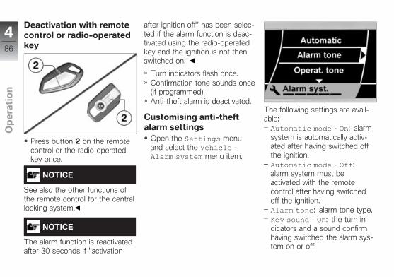
Deactivation with remotecontrol or radio-operatedkey
Press button 2 on the remotecontrol or the radio-operatedkey once.
NOTICE
See also the other functions ofthe remote control for the centrallocking system.
NOTICE
The alarm function is reactivatedafter 30 seconds if "activation
after ignition off" has been selec-ted if the alarm function is deac-tivated using the radio-operatedkey and the ignition is not thenswitched on.
Turn indicators flash once.Confirmation tone sounds once(if programmed).Anti-theft alarm is deactivated.
Customising anti-theftalarm settings
Open the Settings menuand select the Vehicle -Alarm system menu item.
The following settings are avail-able:Automatic mode - On: alarmsystem is automatically activ-ated after having switched offthe ignition.Automatic mode - Off:alarm system must beactivated with the remotecontrol after having switchedoff the ignition.Alarm tone: alarm tone type.Key sound - On: the turn in-dicators and a sound confirmhaving switched the alarm sys-tem on or off.
486
z Op
era
tio
n
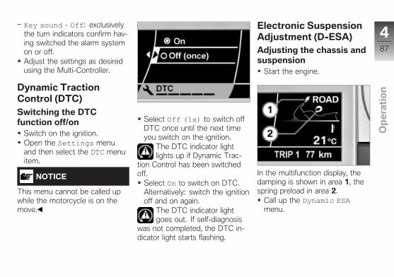
Key sound - Off: exclusivelythe turn indicators confirm hav-ing switched the alarm systemon or off.Adjust the settings as desiredusing the Multi-Controller.
Dynamic TractionControl (DTC)Switching the DTCfunction off/on
Switch on the ignition.Open the Settings menuand then select the DTC menuitem.
NOTICE
This menu cannot be called upwhile the motorcycle is on themove.
Select Off (1x) to switch offDTC once until the next timeyou switch on the ignition.
The DTC indicator lightlights up if Dynamic Trac-
tion Control has been switchedoff.
Select On to switch on DTC.Alternatively: switch the ignitionoff and on again.
The DTC indicator lightgoes out. If self-diagnosis
was not completed, the DTC in-dicator light starts flashing.
Electronic SuspensionAdjustment (DESA)Adjusting the chassis andsuspension
Start the engine.
In the multifunction display, thedamping is shown in area 1, thespring preload in area 2.
Call up the Dynamic ESAmenu.
487
z Op
era
tio
n
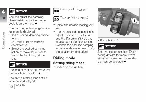
NOTICE
You can adjust the dampingcharacteristic while the motor-cycle is on the move.
The damping action range of ad-justment is displayed.ROAD: Normal damping charac-teristicDYNAMIC: Sporty dampingcharacteristicSelect the desired dampingaction or move the cursor to-wards the top to adjust theload.
NOTICE
The load cannot be set while themotorcycle is in motion.
The spring preload range of ad-justment is displayed.
One-up
One-up with luggage
Two-up (with luggage)
Select the desired loading vari-ant.The chassis and suspension isadjusted as per the selectionand the Dynamic ESA displayis adapted to the new setting.Symbols for load and dampingaction are shown in grey duringthe adjustment procedure.
Riding modeSetting riding mode
Switch on the ignition.
Press button 1.
NOTICE
See the section entitled "Engin-eering details" for more inform-ation on the various ride modesthat can be selected.
488
z Op
era
tio
n

The current setting is shown atposition 2; each time the buttonis pressed one of the possibleriding modes is shown at posi-tion 3.
Press the button until the de-sired riding mode is displayed.With the motorcycle at a stand-still, the mode you select isactivated after a short time.The newly selected ridingmode is activated as youride only when the followingpreconditions are satisfied:Brake not operated
Throttle grip in fully closed po-sitionOnce the new riding mode hasbeen activated, the selectiondisplay is no longer shown.The adjusted riding mode withthe corresponding adaptationsof the engine characteristicsand DTC also remains activ-ated after having switched offthe ignition.
Cruise-control systemSwitching on cruisecontrol
Slide switch 1 to the right.
Button 2 is operational.
Saving road speed
Briefly push button 2 forward.
NOTICE
The cruise control can be setwithin a speed range from30 km⁄/h to 220 km⁄h.
Telltale light for cruise con-trol shows.
The motorcycle maintains yourcurrent cruising speed and thesetting is saved.
489
z Op
era
tio
n
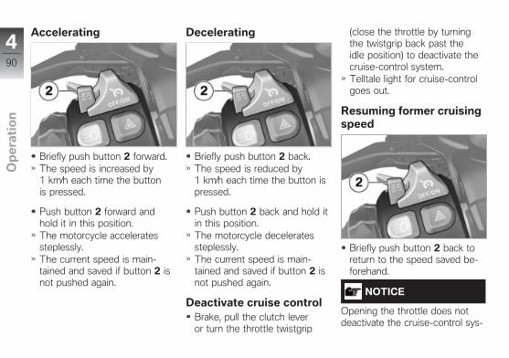
Accelerating
Briefly push button 2 forward.The speed is increased by1 km⁄h each time the buttonis pressed.
Push button 2 forward andhold it in this position.The motorcycle acceleratessteplessly.The current speed is main-tained and saved if button 2 isnot pushed again.
Decelerating
Briefly push button 2 back.The speed is reduced by1 km⁄h each time the button ispressed.
Push button 2 back and hold itin this position.The motorcycle deceleratessteplessly.The current speed is main-tained and saved if button 2 isnot pushed again.
Deactivate cruise controlBrake, pull the clutch leveror turn the throttle twistgrip
(close the throttle by turningthe twistgrip back past theidle position) to deactivate thecruise-control system.Telltale light for cruise-controlgoes out.
Resuming former cruisingspeed
Briefly push button 2 back toreturn to the speed saved be-forehand.
NOTICE
Opening the throttle does notdeactivate the cruise-control sys-
490
z Op
era
tio
n
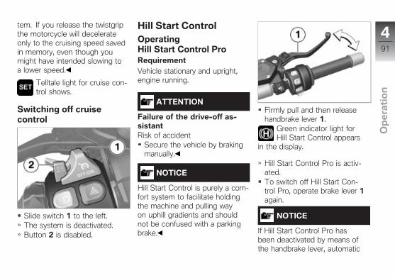
tem. If you release the twistgripthe motorcycle will decelerateonly to the cruising speed savedin memory, even though youmight have intended slowing toa lower speed.
Telltale light for cruise con-trol shows.
Switching off cruisecontrol
Slide switch 1 to the left.The system is deactivated.Button 2 is disabled.
Hill Start ControlOperatingHill Start Control ProRequirementVehicle stationary and upright,engine running.
ATTENTION
Failure of the drive-off as-sistantRisk of accident
Secure the vehicle by brakingmanually.
NOTICE
Hill Start Control is purely a com-fort system to facilitate holdingthe machine and pulling wayon uphill gradients and shouldnot be confused with a parkingbrake.
Firmly pull and then releasehandbrake lever 1.
Green indicator light forHill Start Control appears
in the display.
Hill Start Control Pro is activ-ated.To switch off Hill Start Con-trol Pro, operate brake lever 1again.
NOTICE
If Hill Start Control Pro hasbeen deactivated by means ofthe handbrake lever, automatic
491
z Op
era
tio
n
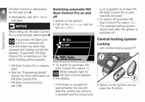
Hill Start Control is deactivatedfor the next 4 m.
Alternatively, ride off in 1st or2nd gear.
NOTICE
When riding off, Hill Start ControlPro is automatically deactivated.
If automatic Hill Start Con-trol Pro is switched off,
once the brake has been fullyreleased, the holding symbol dis-appears. If automatic Hill StartControl Pro is switched on, thewhite holding symbol appears.
Hill Start Control Pro is deactiv-ated.See the "Engineering details"section for more information onHill Start Control Pro:Hill Start Control function( 159)
Switching automatic HillStart Control Pro on andoff
Switch on the ignition.Call up the Settings and se-lect HSC AUTO.
To switch on automatic HillStart Control Pro, select On.
White indicator light forHill Start Control appears
in the display.
If the brake is actuated forapproximately one secondafter the vehicle has come toa standstill and the motorcycle
is on a gradient of at least 5%,Hill Start Control Pro is auto-matically activated.To switch off automatic HillStart Control Pro, select Off.The selected setting remainsstored even after the ignition isswitched off.
Central locking systemLocking
with central locking systemOE
Switch on the ignition and op-erate the 1 button.
492
z Op
era
tio
n

NOTICE
Only vehicles without KeylessRide are shipped accompaniedby a separate remote control forthe central locking system andthe alarm system.
Alternatively: operate the 2button of the remote control orradio-operated key.The storage compartments inthe side trim panels and thecases are locked.Topcase locks.These locks can no longer beunlocked manually.
The locked symbol appearson the display.
with anti-theft alarm (DWA) OE
The remote control functionsfor the alarm system have beendescribed in the correspondingsections.
Unlockingwith central locking systemOE
Switch on the ignition and op-erate the 1 button.Alternatively: operate the 2button of the remote control orradio-operated key.The storage compartments inthe side trim panels and thecases are unlocked.Topcase unlocks.Locks that have been lockedmanually must also be manu-ally unlocked again.
with anti-theft alarm (DWA) OE
The remote control functionsfor the alarm system have beendescribed in the correspondingsections.with floor lightingOA
If the component is unlockedwhen the ignition is switchedoff using the remote control,the ground light is brieflyswitched on.
Emergency unlockingwith central locking systemOE
If the central locking system re-fuses to unlock, you can openthe cases, topcase and storagecompartments manually. Theprocedure is as follows:
Removing cases ( 196).Open cases ( 195).Opening topcase ( 197).
493
z Op
era
tio
n
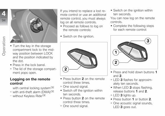
Turn the key in the storagecompartment lock to the mid-way position between LOCKand the position indicated bythe dot.Press in the lock barrel.The lid of the storage compart-ment pops open.
Logging on the remotecontrol
with central locking systemOE
with anti-theft alarm (DWA) OE
without Keyless Ride OE
If you intend to replace a lost re-mote control or use an additionalremote control, you must alwayslog on all remote controls.
Proceed as follows to log onthe remote controls:
Switch on the ignition.
Press button 2 on the remotecontrol three times.One sound signal.Switch off the ignition withinten seconds.Press button 2 on the remotecontrol three times.One sound signal.
Switch on the ignition withinten seconds.
You can now log on the remotecontrols.
Complete the following stepsfor each remote control:
Press and hold down buttons 1and 2.LED 3 flashes for approxim-ately ten seconds.When LED 3 stops flashing,release buttons 1 and 2.LED 3 lights up.Press button 1 or button 2.One acoustic signal sounds,LED 3 goes out.
494
z Op
era
tio
n
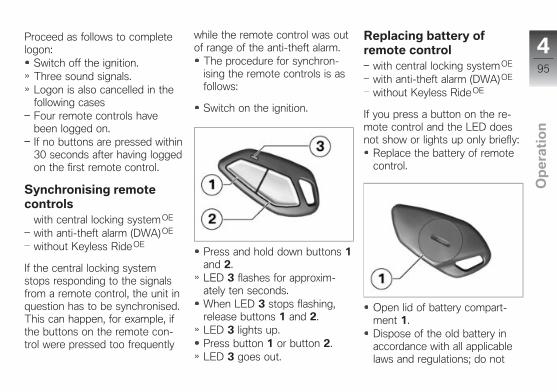
Proceed as follows to completelogon:
Switch off the ignition.Three sound signals.Logon is also cancelled in thefollowing casesFour remote controls havebeen logged on.If no buttons are pressed within30 seconds after having loggedon the first remote control.
Synchronising remotecontrols
with central locking systemOE
with anti-theft alarm (DWA) OE
without Keyless Ride OE
If the central locking systemstops responding to the signalsfrom a remote control, the unit inquestion has to be synchronised.This can happen, for example, ifthe buttons on the remote con-trol were pressed too frequently
while the remote control was outof range of the anti-theft alarm.
The procedure for synchron-ising the remote controls is asfollows:
Switch on the ignition.
Press and hold down buttons 1and 2.LED 3 flashes for approxim-ately ten seconds.When LED 3 stops flashing,release buttons 1 and 2.LED 3 lights up.Press button 1 or button 2.LED 3 goes out.
Replacing battery ofremote control
with central locking systemOE
with anti-theft alarm (DWA) OE
without Keyless Ride OE
If you press a button on the re-mote control and the LED doesnot show or lights up only briefly:
Replace the battery of remotecontrol.
Open lid of battery compart-ment 1.Dispose of the old battery inaccordance with all applicablelaws and regulations; do not
495
z Op
era
tio
n

attempt to dispose of batteriesas domestic waste.
ATTENTION
Unsuitable or incorrectly in-serted batteriesComponent damage
Use a battery compliant withthe manufacturer's specifica-tions.When inserting the battery,always make sure polarity iscorrect.
Insert the new battery with thepositive terminal up.
Battery type and batteryrated voltage
For remote control
CR 20323 V
The LED on the remote controllights up; the remote controlhas to be synchronised.
Press button 1 twice.LED 3 flashes for a fewseconds.The remote control is againready for use.
Grip heatingOperating the grip heating
Start the engine.
NOTICE
The heating in the heatedhandlebar grips can be activatedonly when the engine isrunning.
Open the Grip heatingmenu.
There are five stages of gripheating. Stage five is intendedto quickly heat up the grips, sub-sequently switch to one of thelower stages.
Select the desired heatingstage.
496
z Op
era
tio
n
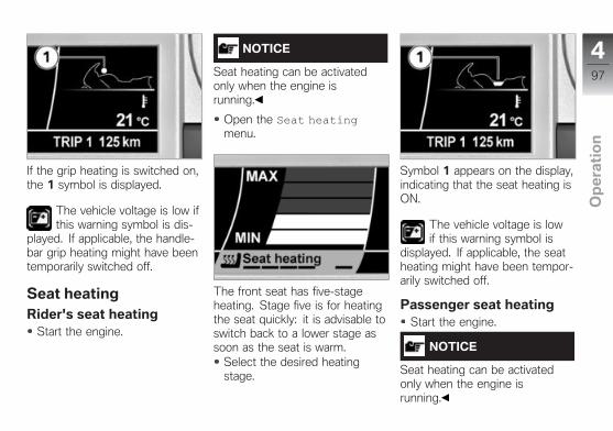
If the grip heating is switched on,the 1 symbol is displayed.
The vehicle voltage is low ifthis warning symbol is dis-
played. If applicable, the handle-bar grip heating might have beentemporarily switched off.
Seat heatingRider's seat heating
Start the engine.
NOTICE
Seat heating can be activatedonly when the engine isrunning.
Open the Seat heatingmenu.
The front seat has five-stageheating. Stage five is for heatingthe seat quickly: it is advisable toswitch back to a lower stage assoon as the seat is warm.
Select the desired heatingstage.
Symbol 1 appears on the display,indicating that the seat heating isON.
The vehicle voltage is lowif this warning symbol is
displayed. If applicable, the seatheating might have been tempor-arily switched off.
Passenger seat heatingStart the engine.
NOTICE
Seat heating can be activatedonly when the engine isrunning.
497
z Op
era
tio
n
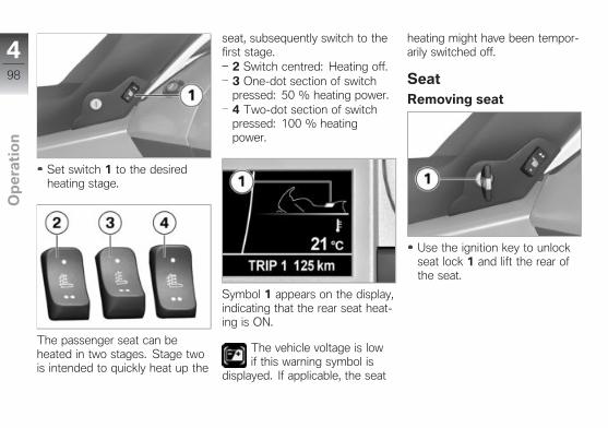
Set switch 1 to the desiredheating stage.
The passenger seat can beheated in two stages. Stage twois intended to quickly heat up the
seat, subsequently switch to thefirst stage.
2 Switch centred: Heating off.3 One-dot section of switchpressed: 50 % heating power.4 Two-dot section of switchpressed: 100 % heatingpower.
Symbol 1 appears on the display,indicating that the rear seat heat-ing is ON.
The vehicle voltage is lowif this warning symbol is
displayed. If applicable, the seat
heating might have been tempor-arily switched off.
SeatRemoving seat
Use the ignition key to unlockseat lock 1 and lift the rear ofthe seat.
498
z Op
era
tio
n
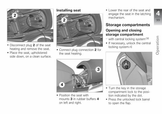
Disconnect plug 2 of the seatheating and remove the seat.Place the seat, upholsteredside down, on a clean surface.
Installing seat
Connect plug connection 2 forthe seat heating.
Position the seat withmounts 3 in rubber buffers 4on left and right.
Lower the rear of the seat andengage the seat in the latchingmechanism.
Storage compartmentsOpening and closingstorage compartment
with central locking systemOE
If necessary, unlock the centrallocking system.
Turn the key in the storagecompartment lock to the posi-tion indicated by the dot.Press the unlocked lock barrelto open the flap.
499
z Op
era
tio
n
The description applies by ana-logy to the storage compart-ment on the right side.
ATTENTION
High temperatures in thestorage compartments, par-ticularly in summerDamage to objects stowed away,particularly electronic devices,such as mobile phones and MP3players
Consult the operating instruc-tions of your electronic deviceand check for possible usagerestrictions.
In summer, do not place heat-sensitive objects in the storagecompartments.
4100
z Op
era
tio
n
Audio system
General operation . . . . . . . . . . . . . . . . . . 102
Radio . . . . . . . . . . . . . . . . . . . . . . . . . . . . . . 109
Satellite radio . . . . . . . . . . . . . . . . . . . . . . 114
External playback devices . . . . . . . . . . 119
Audio playback . . . . . . . . . . . . . . . . . . . . 122
Bluetooth . . . . . . . . . . . . . . . . . . . . . . . . . . 123
5101
z Au
dio
sy
ste
m
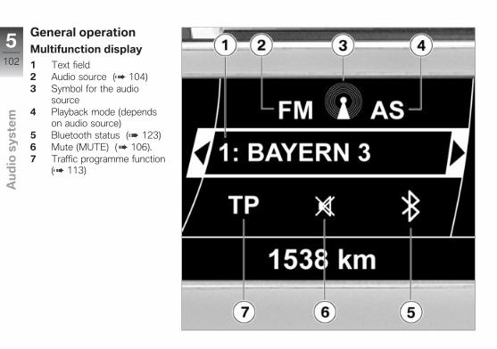
General operationMultifunction display
1 Text field2 Audio source ( 104)3 Symbol for the audio
source4 Playback mode (depends
on audio source)5 Bluetooth status ( 123)6 Mute (MUTE) ( 106).7 Traffic programme function
( 113)
5102
z Au
dio
sy
ste
m
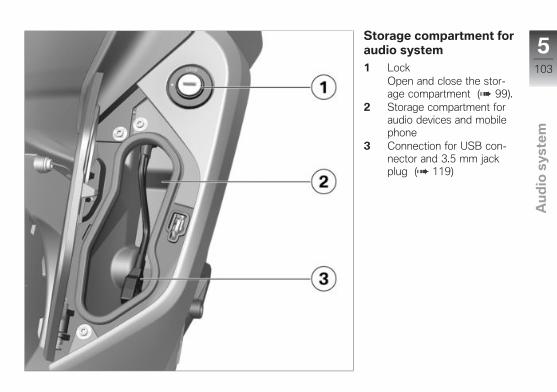
Storage compartment foraudio system
1 LockOpen and close the stor-age compartment ( 99).
2 Storage compartment foraudio devices and mobilephone
3 Connection for USB con-nector and 3.5 mm jackplug ( 119)
5103
z Au
dio
sy
ste
m
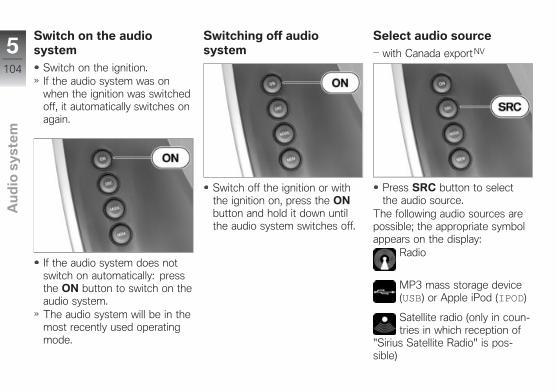
Switch on the audiosystem
Switch on the ignition.If the audio system was onwhen the ignition was switchedoff, it automatically switches onagain.
If the audio system does notswitch on automatically: pressthe ON button to switch on theaudio system.The audio system will be in themost recently used operatingmode.
Switching off audiosystem
Switch off the ignition or withthe ignition on, press the ONbutton and hold it down untilthe audio system switches off.
Select audio source
with Canada exportNV
Press SRC button to selectthe audio source.
The following audio sources arepossible; the appropriate symbolappears on the display:
Radio
MP3 mass storage device(USB) or Apple iPod (IPOD)
Satellite radio (only in coun-tries in which reception of
"Sirius Satellite Radio" is pos-sible)
5104
z Au
dio
sy
ste
m
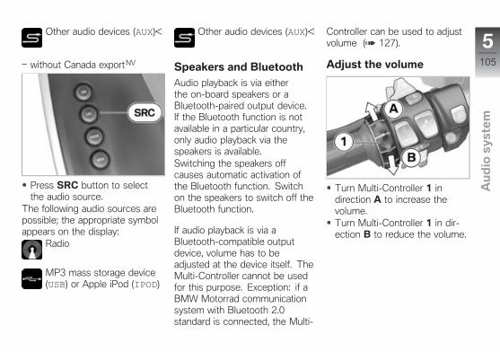
Other audio devices (AUX)
without Canada exportNV
Press SRC button to selectthe audio source.
The following audio sources arepossible; the appropriate symbolappears on the display:
Radio
MP3 mass storage device(USB) or Apple iPod (IPOD)
Other audio devices (AUX)
Speakers and Bluetooth
Audio playback is via eitherthe on-board speakers or aBluetooth-paired output device.If the Bluetooth function is notavailable in a particular country,only audio playback via thespeakers is available.Switching the speakers offcauses automatic activation ofthe Bluetooth function. Switchon the speakers to switch off theBluetooth function.
If audio playback is via aBluetooth-compatible outputdevice, volume has to beadjusted at the device itself. TheMulti-Controller cannot be usedfor this purpose. Exception: if aBMW Motorrad communicationsystem with Bluetooth 2.0standard is connected, the Multi-
Controller can be used to adjustvolume ( 127).
Adjust the volume
Turn Multi-Controller 1 indirection A to increase thevolume.Turn Multi-Controller 1 in dir-ection B to reduce the volume.
5105
z Au
dio
sy
ste
m
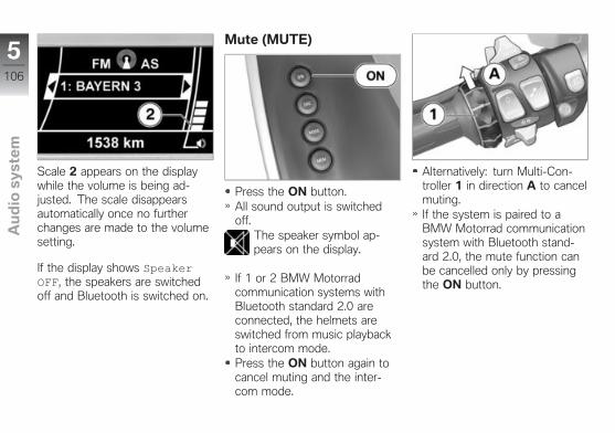
Scale 2 appears on the displaywhile the volume is being ad-justed. The scale disappearsautomatically once no furtherchanges are made to the volumesetting.
If the display shows SpeakerOFF, the speakers are switchedoff and Bluetooth is switched on.
Mute (MUTE)
Press the ON button.All sound output is switchedoff.
The speaker symbol ap-pears on the display.
If 1 or 2 BMW Motorradcommunication systems withBluetooth standard 2.0 areconnected, the helmets areswitched from music playbackto intercom mode.Press the ON button again tocancel muting and the inter-com mode.
Alternatively: turn Multi-Con-troller 1 in direction A to cancelmuting.If the system is paired to aBMW Motorrad communicationsystem with Bluetooth stand-ard 2.0, the mute function canbe cancelled only by pressingthe ON button.
5106
z Au
dio
sy
ste
m
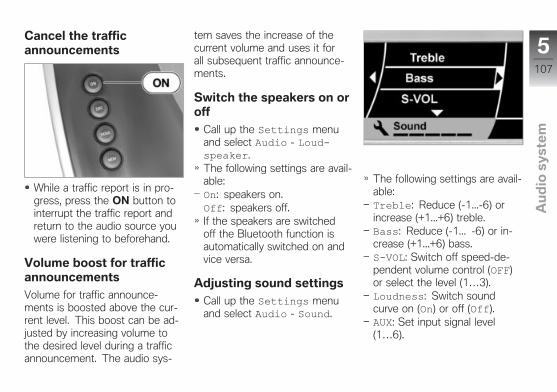
Cancel the trafficannouncements
While a traffic report is in pro-gress, press the ON button tointerrupt the traffic report andreturn to the audio source youwere listening to beforehand.
Volume boost for trafficannouncements
Volume for traffic announce-ments is boosted above the cur-rent level. This boost can be ad-justed by increasing volume tothe desired level during a trafficannouncement. The audio sys-
tem saves the increase of thecurrent volume and uses it forall subsequent traffic announce-ments.
Switch the speakers on oroff
Call up the Settings menuand select Audio - Loudspeaker.The following settings are avail-able:On: speakers on.Off: speakers off.If the speakers are switchedoff the Bluetooth function isautomatically switched on andvice versa.
Adjusting sound settings
Call up the Settings menuand select Audio - Sound.
The following settings are avail-able:Treble: Reduce (-1...-6) orincrease (+1...+6) treble.Bass: Reduce (-1... -6) or in-crease (+1...+6) bass.SVOL: Switch off speed-de-pendent volume control (OFF)or select the level (1…3).Loudness: Switch soundcurve on (On) or off (Off).AUX: Set input signal level(1…6).
5107
z Au
dio
sy
ste
m

Fader: Adjust front/rearvolume balance (-10…+10).Select the menu item youwant, select the setting of yourchoice and exit the menu.
Volume and speed
The audio system can auto-matically adapt the volume tothe driving speed. The increasein volume in dependence onthe speed can be set to threelevels. Level 3 corresponds tothe largest increase.Automatic volume adjustmentdoes not work for playback viaBluetooth-connected communic-ation systems.
Input signal level
The volume can be set as de-scribed on page ( 105).In the case of audio devices thatcan only be connected to thesystem via the jack, the volumethat can be set depends on:
the output power of the audiodevicethe input-signal level you selectthe volume to which the audiodevice is set.
You should set the input-sig-nal level and adjust the volumeof the audio device in such away that the volume range avail-able for adjustment correspondsto that of the other operatingmodes.
5108
z Au
dio
sy
ste
m
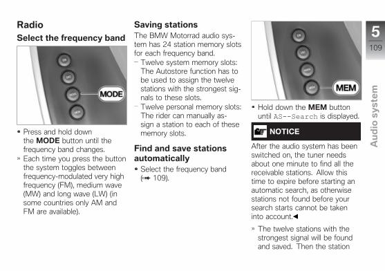
RadioSelect the frequency band
Press and hold downthe MODE button until thefrequency band changes.Each time you press the buttonthe system toggles betweenfrequency-modulated very highfrequency (FM), medium wave(MW) and long wave (LW) (insome countries only AM andFM are available).
Saving stationsThe BMW Motorrad audio sys-tem has 24 station memory slotsfor each frequency band.
Twelve system memory slots:The Autostore function has tobe used to assign the twelvestations with the strongest sig-nals to these slots.Twelve personal memory slots:The rider can manually as-sign a station to each of thesememory slots.
Find and save stationsautomatically
Select the frequency band( 109).
Hold down the MEM buttonuntil ASSearch is displayed.
NOTICE
After the audio system has beenswitched on, the tuner needsabout one minute to find all thereceivable stations. Allow thistime to expire before starting anautomatic search, as otherwisestations not found before yoursearch starts cannot be takeninto account.
The twelve stations with thestrongest signal will be foundand saved. Then the station
5109
z Au
dio
sy
ste
m
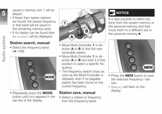
saved in memory slot 1 will beplayed.If fewer then twelve stationsare found, the lowest frequencyin that band will be saved inthe remaining memory slots.If no station can be found thenNo signal will be displayed.
Station search, manualSelect the frequency band( 109).
Repeatedly press the MODEbutton until MAN appears in thetop line of the display.
Move Multi-Controller 1 in dir-ection A or B to find the nextreceivable station.Move Multi-Controller 1 in dir-ection A or B and hold it in thisposition to select a specific fre-quency.The frequency search stops assoon as the Multi-Controller isreleased, even if no playablestation has been found on thecurrent frequency.
Station save, manualSelect a station or frequencyfrom the frequency band.
NOTICE
It is also possible to select sta-tions from the system memory orthe personal memory and thenmove them to a different slot inthe personal memory.
Press the MEM button to savethe selected frequency / sta-tion.Memory will flash on thedisplay.
5110
z Au
dio
sy
ste
m

Move Multi-Controller 1 in dir-ection A or B to select therequired slot in the personalmemory list.The current assignment of thismemory slot flashes on thedisplay.
Press the MEM button againto save the station / frequencyto the selected memory slot.The station previously savedthere will be deleted.
Call up the stations savedin memory
Select the frequency band( 109).
To select a station fromthe system memory, pressthe MODE button repeatedlyuntil AS is displayed.
5111
z Au
dio
sy
ste
m
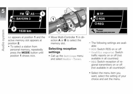
AS appears at position 1 and theactive memory slot appears atposition 2.
To select a station frompersonal memory, repeatedlypress the MODE button untilposition 1 shows MEM.
Move Multi-Controller 1 in dir-ection A or B to select thememory slot.
Selecting receptionsettings
Call up the Settings menuand select Audio - Tuner.
The following settings are avail-able:RDS: Switch RDS on or offTraffic reports: Switchtraffic reports on or off (notavailable in all countries)REG: Switch reception of re-gional transmitters on or off(not available in all countries)
Select the menu item youwant, select the setting of yourchoice and exit the menu.
5112
z Au
dio
sy
ste
m

Radio Data System (RDS)Some stations broadcasting inthe FM waveband transmit addi-tional information, including pro-gramme names.The name of the station can onlybe displayed if the RDS functionis on. If no station name is trans-mitted, waveband and frequencyare shown in the display.
Traffic channelIf a station broadcasting on theFM waveband transmits trafficannouncements, this is in manycountries included in the RDSsignals ( 113).
If at least one station with trafficannouncements is being receivedby the audio system, area 1 con-tains a T symbol. The trafficchannel station does not neces-sarily have to be the same as thestation that is currently playing.You can switch on the trafficchannel function only if RDS isactive. If the traffic-programmefunction is ON and at least onestation with a traffic channel isreceivable, TP appears at posi-tion 1.If a traffic channel station is be-ing played and the traffic channelfunction is on, any other operat-
ing mode is interrupted for theduration of the announcement.Exception: if communication sys-tems are connected in commu-nication mode, these will not beinterrupted.
Regional broadcastsIn the FM band, stations can useseveral frequencies for their pro-gramming. These may vary fromregion to region. These altern-ative frequencies are containedin the RDS data, which enablesthe audio system to change thefrequency of the station automat-ically according to where it is.Some stations use these dif-ferent frequencies to broadcastdifferent, region-specific pro-grammes at different times ofday. This could mean that theprogramme will change automat-ically if the region is changed,even if the rider has not changedthe station.
5113
z Au
dio
sy
ste
m
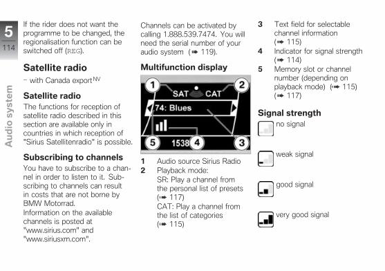
If the rider does not want theprogramme to be changed, theregionalisation function can beswitched off (REG).
Satellite radiowith Canada exportNV
Satellite radioThe functions for reception ofsatellite radio described in thissection are available only incountries in which reception of"Sirius Satellitenradio" is possible.
Subscribing to channelsYou have to subscribe to a chan-nel in order to listen to it. Sub-scribing to channels can resultin costs that are not borne byBMW Motorrad.Information on the availablechannels is posted at"www.sirius.com" and"www.siriusxm.com".
Channels can be activated bycalling 1.888.539.7474. You willneed the serial number of youraudio system ( 119).
Multifunction display
1 Audio source Sirius Radio2 Playback mode:
SR: Play a channel fromthe personal list of presets( 117)CAT: Play a channel fromthe list of categories( 115)
3 Text field for selectablechannel information( 115)
4 Indicator for signal strength( 114)
5 Memory slot or channelnumber (depending onplayback mode) ( 115)( 117)
Signal strengthno signal
weak signal
good signal
very good signal
5114
z Au
dio
sy
ste
m

Select channelinformation
Call up the Settings menuand select menu item Audio -SiriusSirius Info.
The following information typescan be displayed in the text field:Channel n...: Name of thechannelArtist: name of the artistTrack: name of the trackComposer: name of the com-poser
The solid circle indicates thecurrent information.Select the information type youwant and exit the menu.If the information you selectedis not available (e.g. news, butartist and composer selected),the channel name is displayed.
Selecting category andchannel
If the audio system is in thePreset playback mode (SRin the display) or if you wantto change the category: pressthe MODE button.
The choice of playback modeappears on the display.Genre: selection of a channelfrom the list of categoriesPreset: selection from thepersonal list of presetsSelect Genre.
5115
z Au
dio
sy
ste
m

A list of the categoriescorresponding to the channelsfor which a subscription hasbeen paid appears on thedisplay. All channels for whichno subscription has beentaken out are grouped in theunsubscribed category.
The solid circle indicates thecurrent category.Select the category you want.A list of the channels availablein the category you selectedappears on the display.Select the channel you want.
The channel information you se-lected appears in the text field.
If the audio system is alreadyin the Genre playback mode:press Multi-Controller 1 in dir-ection A or B to go to the next
channel in the selected cat-egory.
Save channelSelecting category and channel( 115).
Press the MEM button.Memory is displayed.
5116
z Au
dio
sy
ste
m

Move Multi-Controller 1 in dir-ection A or B to select thememory slot of your choice.The current assignment of thismemory slot flashes on thedisplay.
Press the MEM button againto save the channel to the se-lected memory slot.The channel previously savedthere is deleted.
Calling up channel savedin memory
If the audio system is in theGenre playback mode (CATshowing on the display): pressthe MODE button.
5117
z Au
dio
sy
ste
m
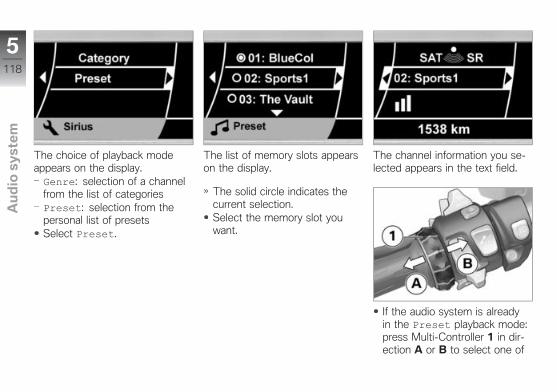
The choice of playback modeappears on the display.Genre: selection of a channelfrom the list of categoriesPreset: selection from thepersonal list of presetsSelect Preset.
The list of memory slots appearson the display.
The solid circle indicates thecurrent selection.Select the memory slot youwant.
The channel information you se-lected appears in the text field.
If the audio system is alreadyin the Preset playback mode:press Multi-Controller 1 in dir-ection A or B to select one of
5118
z Au
dio
sy
ste
m
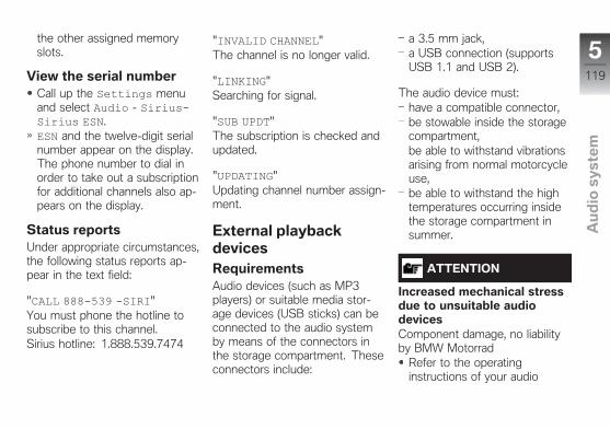
the other assigned memoryslots.
View the serial numberCall up the Settings menuand select Audio - SiriusSirius ESN.ESN and the twelve-digit serialnumber appear on the display.The phone number to dial inorder to take out a subscriptionfor additional channels also ap-pears on the display.
Status reportsUnder appropriate circumstances,the following status reports ap-pear in the text field:
"CALL 888539 SIRI"You must phone the hotline tosubscribe to this channel.Sirius hotline: 1.888.539.7474
"INVALID CHANNEL"The channel is no longer valid.
"LINKING"Searching for signal.
"SUB UPDT"The subscription is checked andupdated.
"UPDATING"Updating channel number assign-ment.
External playbackdevicesRequirementsAudio devices (such as MP3players) or suitable media stor-age devices (USB sticks) can beconnected to the audio systemby means of the connectors inthe storage compartment. Theseconnectors include:
a 3.5 mm jack,a USB connection (supportsUSB 1.1 and USB 2).
The audio device must:have a compatible connector,be stowable inside the storagecompartment,be able to withstand vibrationsarising from normal motorcycleuse,be able to withstand the hightemperatures occurring insidethe storage compartment insummer.
ATTENTION
Increased mechanical stressdue to unsuitable audiodevicesComponent damage, no liabilityby BMW Motorrad
Refer to the operatinginstructions of your audio
5119
z Au
dio
sy
ste
m

device for any possible usagerestrictions.
ATTENTION
High temperatures in thestorage compartmentsDamage to stored objects ordevices
Please refer to the operatinginstructions for the devices tosee if there are any possiblerestrictions on use.
BMW Motorrad advises againstusing devices with hard discs asmedia storage devices, as vibra-tions may cause playback to skipand may damage the device.The audio system provides asupply voltage via the USB plug,though which it is possible tocharge mobile telephones andother such devices. Connect-ing several USB devices via a
hub is not possible as the supplyvoltage is limited.
Connecting audio deviceSwitch off the audio system( 104).
Use USB connector 1 to con-nect the data memory to theaudio system.Connect an Apple iPod withadapter cable to the audio sys-tem using USB connector 1and jack plug 2.
NOTICE
You can obtain the correct ad-apter cable from your authorisedBMW Motorrad retailer.
Connect other audio devicesto the audio system via jackplug 2 and switch on.Position the audio device instorage compartment 3.
ATTENTION
Improper routing of the ac-cess lineDamage to the seal
Do not run the access line out-side between the storage com-partment and the cover.
Close the lid of the compart-ment, making sure that neitherthe audio device nor the cableis trapped.Switch on the audio system( 104).
5120
z Au
dio
sy
ste
m
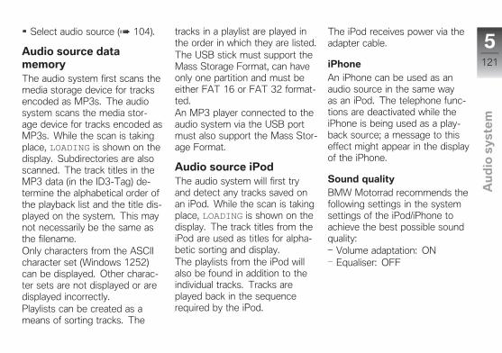
Select audio source ( 104).
Audio source datamemoryThe audio system first scans themedia storage device for tracksencoded as MP3s. The audiosystem scans the media stor-age device for tracks encoded asMP3s. While the scan is takingplace, LOADING is shown on thedisplay. Subdirectories are alsoscanned. The track titles in theMP3 data (in the ID3-Tag) de-termine the alphabetical order ofthe playback list and the title dis-played on the system. This maynot necessarily be the same asthe filename.Only characters from the ASCIIcharacter set (Windows 1252)can be displayed. Other charac-ter sets are not displayed or aredisplayed incorrectly.Playlists can be created as ameans of sorting tracks. The
tracks in a playlist are played inthe order in which they are listed.The USB stick must support theMass Storage Format, can haveonly one partition and must beeither FAT 16 or FAT 32 format-ted.An MP3 player connected to theaudio system via the USB portmust also support the Mass Stor-age Format.
Audio source iPodThe audio system will first tryand detect any tracks saved onan iPod. While the scan is takingplace, LOADING is shown on thedisplay. The track titles from theiPod are used as titles for alpha-betic sorting and display.The playlists from the iPod willalso be found in addition to theindividual tracks. Tracks areplayed back in the sequencerequired by the iPod.
The iPod receives power via theadapter cable.
iPhoneAn iPhone can be used as anaudio source in the same wayas an iPod. The telephone func-tions are deactivated while theiPhone is being used as a play-back source; a message to thiseffect might appear in the displayof the iPhone.
Sound qualityBMW Motorrad recommends thefollowing settings in the systemsettings of the iPod/iPhone toachieve the best possible soundquality:
Volume adaptation: ONEqualiser: OFF
5121
z Au
dio
sy
ste
m
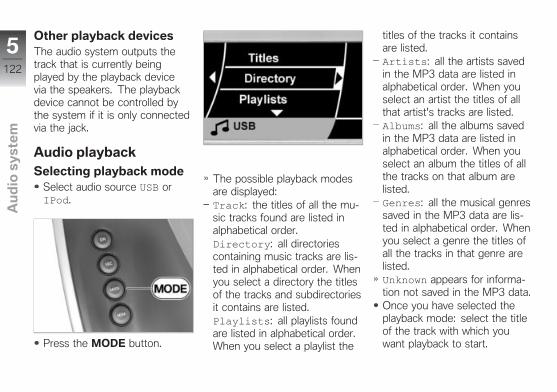
Other playback devicesThe audio system outputs thetrack that is currently beingplayed by the playback devicevia the speakers. The playbackdevice cannot be controlled bythe system if it is only connectedvia the jack.
Audio playbackSelecting playback mode
Select audio source USB orIPod.
Press the MODE button.
The possible playback modesare displayed:Track: the titles of all the mu-sic tracks found are listed inalphabetical order.Directory: all directoriescontaining music tracks are lis-ted in alphabetical order. Whenyou select a directory the titlesof the tracks and subdirectoriesit contains are listed.Playlists: all playlists foundare listed in alphabetical order.When you select a playlist the
titles of the tracks it containsare listed.Artists: all the artists savedin the MP3 data are listed inalphabetical order. When youselect an artist the titles of allthat artist's tracks are listed.Albums: all the albums savedin the MP3 data are listed inalphabetical order. When youselect an album the titles of allthe tracks on that album arelisted.Genres: all the musical genressaved in the MP3 data are lis-ted in alphabetical order. Whenyou select a genre the titles ofall the tracks in that genre arelisted.Unknown appears for informa-tion not saved in the MP3 data.Once you have selected theplayback mode: select the titleof the track with which youwant playback to start.
5122
z Au
dio
sy
ste
m
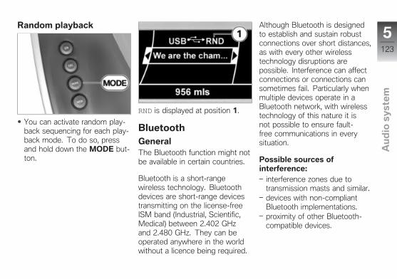
Random playback
You can activate random play-back sequencing for each play-back mode. To do so, pressand hold down the MODE but-ton.
RND is displayed at position 1.
BluetoothGeneralThe Bluetooth function might notbe available in certain countries.
Bluetooth is a short-rangewireless technology. Bluetoothdevices are short-range devicestransmitting on the license-freeISM band (Industrial, Scientific,Medical) between 2.402 GHzand 2.480 GHz. They can beoperated anywhere in the worldwithout a licence being required.
Although Bluetooth is designedto establish and sustain robustconnections over short distances,as with every other wirelesstechnology disruptions arepossible. Interference can affectconnections or connections cansometimes fail. Particularly whenmultiple devices operate in aBluetooth network, with wirelesstechnology of this nature it isnot possible to ensure fault-free communications in everysituation.
Possible sources ofinterference:
interference zones due totransmission masts and similar.devices with non-compliantBluetooth implementations.proximity of other Bluetooth-compatible devices.
5123
z Au
dio
sy
ste
m

Note on health compatibility:The body of scientific dataavailable at this time gives nogrounds for assuming thatBluetooth can have negativeeffects on human health. TheBMW Motorrad audio systemtransmits at a maximum of10 mW; a mobile phone bycontrast can have a transmit-power rating as high as 2 W.The ISM frequency band usedby Bluetooth is reserved for theworld-wide use of devices in theindustrial, scientific and med-ical sectors and given the lowtransmit-power ratings, Bluetoothdevices are considered safe interms of potential health risks.
Playback via helmetThe audio system can be con-nected to the Bluetooth-compat-ible BMW Motorrad communic-ation systems. Playback in thiscase is not through the speak-
ers, but by wireless transmissionthrough the headphones in thehelmet.
Switch the Bluetoothfunction on and off
To switch on the Bluetoothfunction: switch off the speak-ers.To switch off the Bluetoothfunction: switch on the speak-ers.Switch the speakers on or off( 107).
Bluetooth symbol 1 appears onthe display.
A dot to the left of theBluetooth symbol indic-
ates that the audio system isconnected to the rider's helmet(Helmet1). A dot to the right ofthe Bluetooth symbol indicatesa connection to the passenger'shelmet (Helmet2). A flashing dotindicates that the audio system issearching for the correspondinghelmet.
If pairing information for a com-munication system is saved inthe audio system's memory,the audio system automaticallysearches for this system.
If connection to a BMW Motorradcommunication system is notestablished despite the fact thatthe system is switched on:
Briefly press the on/off buttonof the communication systemtwice in quick succession.
5124
z Au
dio
sy
ste
m
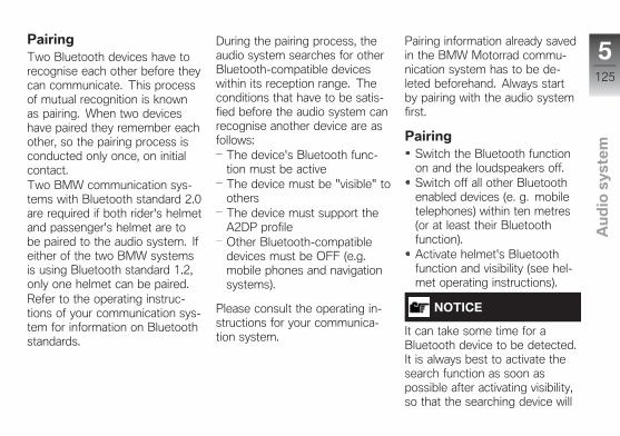
PairingTwo Bluetooth devices have torecognise each other before theycan communicate. This processof mutual recognition is knownas pairing. When two deviceshave paired they remember eachother, so the pairing process isconducted only once, on initialcontact.Two BMW communication sys-tems with Bluetooth standard 2.0are required if both rider's helmetand passenger's helmet are tobe paired to the audio system. Ifeither of the two BMW systemsis using Bluetooth standard 1.2,only one helmet can be paired.Refer to the operating instruc-tions of your communication sys-tem for information on Bluetoothstandards.
During the pairing process, theaudio system searches for otherBluetooth-compatible deviceswithin its reception range. Theconditions that have to be satis-fied before the audio system canrecognise another device are asfollows:
The device's Bluetooth func-tion must be activeThe device must be "visible" toothersThe device must support theA2DP profileOther Bluetooth-compatibledevices must be OFF (e.g.mobile phones and navigationsystems).
Please consult the operating in-structions for your communica-tion system.
Pairing information already savedin the BMW Motorrad commu-nication system has to be de-leted beforehand. Always startby pairing with the audio systemfirst.
PairingSwitch the Bluetooth functionon and the loudspeakers off.Switch off all other Bluetoothenabled devices (e. g. mobiletelephones) within ten metres(or at least their Bluetoothfunction).Activate helmet's Bluetoothfunction and visibility (see hel-met operating instructions).
NOTICE
It can take some time for aBluetooth device to be detected.It is always best to activate thesearch function as soon aspossible after activating visibility,so that the searching device will
5125
z Au
dio
sy
ste
m
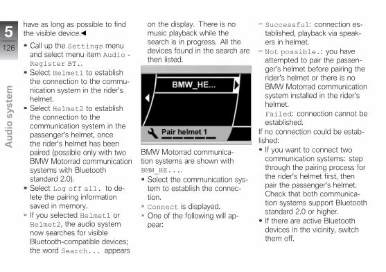
have as long as possible to findthe visible device.
Call up the Settings menuand select menu item Audio -Register BT..Select Helmet1 to establishthe connection to the commu-nication system in the rider'shelmet.Select Helmet2 to establishthe connection to thecommunication system in thepassenger's helmet, oncethe rider's helmet has beenpaired (possible only with twoBMW Motorrad communicationsystems with Bluetoothstandard 2.0).Select Log off all. to de-lete the pairing informationsaved in memory.If you selected Helmet1 orHelmet2, the audio systemnow searches for visibleBluetooth-compatible devices;the word Search... appears
on the display. There is nomusic playback while thesearch is in progress. All thedevices found in the search arethen listed.
BMW Motorrad communica-tion systems are shown withBMW_HE....
Select the communication sys-tem to establish the connec-tion.Connect is displayed.One of the following will ap-pear:
Successful: connection es-tablished, playback via speak-ers in helmet.Not possible.: you haveattempted to pair the passen-ger's helmet before pairing therider's helmet or there is noBMW Motorrad communicationsystem installed in the rider'shelmet.Failed: connection cannot beestablished.
If no connection could be estab-lished:
If you want to connect twocommunication systems: stepthrough the pairing process forthe rider's helmet first, thenpair the passenger's helmet.Check that both communica-tion systems support Bluetoothstandard 2.0 or higher.If there are active Bluetoothdevices in the vicinity, switchthem off.
5126
z Au
dio
sy
ste
m
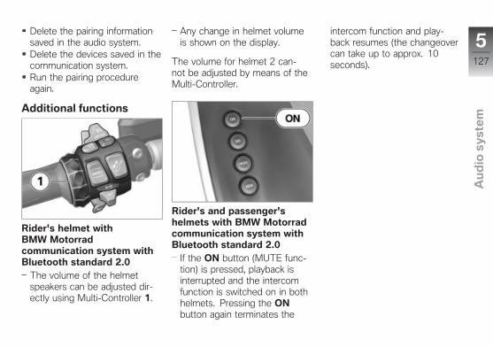
Delete the pairing informationsaved in the audio system.Delete the devices saved in thecommunication system.Run the pairing procedureagain.
Additional functions
Rider's helmet withBMW Motorradcommunication system withBluetooth standard 2.0
The volume of the helmetspeakers can be adjusted dir-ectly using Multi-Controller 1.
Any change in helmet volumeis shown on the display.
The volume for helmet 2 can-not be adjusted by means of theMulti-Controller.
Rider's and passenger'shelmets with BMW Motorradcommunication system withBluetooth standard 2.0
If the ON button (MUTE func-tion) is pressed, playback isinterrupted and the intercomfunction is switched on in bothhelmets. Pressing the ONbutton again terminates the
intercom function and play-back resumes (the changeovercan take up to approx. 10seconds).
5127
z Au
dio
sy
ste
m

5128
z Au
dio
sy
ste
m
Adjustment
Mirrors . . . . . . . . . . . . . . . . . . . . . . . . . . . . . 130
Windscreen . . . . . . . . . . . . . . . . . . . . . . . . 130
Slipstream deflector . . . . . . . . . . . . . . . 131
Clutch . . . . . . . . . . . . . . . . . . . . . . . . . . . . . 131
Brakes . . . . . . . . . . . . . . . . . . . . . . . . . . . . . 132
6129
z Ad
just
me
nt
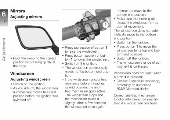
MirrorsAdjusting mirrors
Pivot the mirror to the correctposition by pressing gently atthe edge.
WindscreenAdjusting windscreen
Switch on the ignition.As you ride off, the windscreenautomatically moves to its lastposition before the ignition wasswitched off.
Press top section of button 1to raise the windscreen.Press bottom section of but-ton 1 to lower the windscreen.Switch off the ignition.The windscreen automaticallymoves to the bottom end posi-tion.If the windscreen encountersresistance before it reachesits end position, the anti-trap mechanism goes active.The windscreen stops andthe mechanism raises itslightly. After a few secondsthe windscreen once again
attempts to move to thebottom end position.Make sure that nothing ob-structs the windscreen's free-dom of movement.
The windscreen does not auto-matically move to the bottomend position:
Switch on the ignition.Press button 1 to move thewindscreen to its top and bot-tom end positions.Switch off the ignition.The windscreen's range of ad-justment is calibrated.
Windscreen does not react whenbutton 1 is pressed:
Consult a specialist workshop,preferably an authorisedBMW Motorrad dealer.
Correct anti-trap mechanismfunctionality cannot be guaran-teed if a windscreen has been
6130
z Ad
just
me
nt
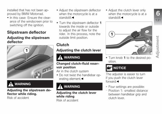
installed that has not been ap-proved by BMW Motorrad.
In this case: Ensure the clear-ance of the windscreen prior toswitching off the ignition.
Slipstream deflectorAdjusting the slipstreamdeflector
WARNING
Adjusting the slipstream de-flector while riding.Risk of accident
Adjust the slipstream deflectorwhen the motorcycle is at astandstill.
Turn the slipstream deflector 1towards the inside or outsideto adjust the air flow for therider. In this process, note theoutside limit position.
ClutchAdjusting the clutch lever
WARNING
Changed clutch-fluid reser-voir positionAir in the clutch system
Do not twist the handlebar op-erating element.
WARNING
Adjusting the clutch leverwhile ridingRisk of accident
Adjust the clutch lever onlywhen the motorcycle is at astandstill.
Turn knob 1 to the desired po-sition.
NOTICE
The adjuster is easier to turnif you push the clutch leverforward.
Four settings are possible:Position 1: smallest distancebetween handlebar grip andclutch lever.
6131
z Ad
just
me
nt
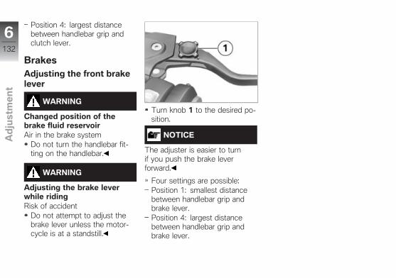
Position 4: largest distancebetween handlebar grip andclutch lever.
BrakesAdjusting the front brakelever
WARNING
Changed position of thebrake fluid reservoirAir in the brake system
Do not turn the handlebar fit-ting on the handlebar.
WARNING
Adjusting the brake leverwhile ridingRisk of accident
Do not attempt to adjust thebrake lever unless the motor-cycle is at a standstill.
Turn knob 1 to the desired po-sition.
NOTICE
The adjuster is easier to turnif you push the brake leverforward.
Four settings are possible:Position 1: smallest distancebetween handlebar grip andbrake lever.Position 4: largest distancebetween handlebar grip andbrake lever.
6132
z Ad
just
me
nt
Riding
Safety information . . . . . . . . . . . . . . . . . 134
Regular check . . . . . . . . . . . . . . . . . . . . . 136
Starting . . . . . . . . . . . . . . . . . . . . . . . . . . . . 136
Running in . . . . . . . . . . . . . . . . . . . . . . . . . 138
Brakes . . . . . . . . . . . . . . . . . . . . . . . . . . . . . 139
Parking your motorcycle . . . . . . . . . . . 141
Refuelling . . . . . . . . . . . . . . . . . . . . . . . . . . 142
Securing motorcycle for transporta-tion . . . . . . . . . . . . . . . . . . . . . . . . . . . . . . . . 146
7133
z Rid
ing
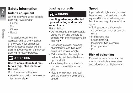
Safety informationRider's equipmentDo not ride without the correctclothing! Always wear:
HelmetSuitGlovesBoots
This applies even to shortjourneys, and to every seasonof the year. Your authorisedBMW Motorrad dealer will beglad to advise you on the correctclothing for every purpose.
ATTENTION
Use of non-colour-fast ma-terials (e.g. blue jeans) onthe seatDiscolouration on the seat
Avoid contact with non-colour-fast materials.
Loading correctly
WARNING
Handling adversely affectedby overloading and imbal-anced loadsRisk of falling
Do not exceed the permissiblegross weight and be sure tocomply with the instructions onloading.
Set spring preload, dampingcharacteristic and tyre pres-sures to suit total weight.Make sure that the weight isuniformly distributed betweenright and left.Pack heavy items at the bot-tom and toward the inboardside.Note the maximum payloadand the maximum permissiblespeed.
SpeedIf you ride at high speed, alwaysbear in mind that various bound-ary conditions can adversely af-fect the handling of your motor-cycle:
Spring-strut and shock-ab-sorber system not set up cor-rectlyImbalanced loadLoose clothingInsufficient tyre pressurePoor tyre treadEtc.
Risk of poisoningExhaust fumes contain carbonmonoxide, which is colourlessand odourless but highly toxic.
7134
z Rid
ing
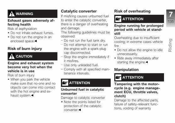
WARNING
Exhaust gases adversely af-fecting healthRisk of asphyxiation
Do not inhale exhaust fumes.Do not run the engine in anenclosed space.
Risk of burn injury
CAUTION
Engine and exhaust systembecome very hot when thevehicle is in useRisk of burn injury
When you park the vehiclemake sure that no-one and noobjects can come into contactwith the hot engine and ex-haust system.
Catalytic converterIf misfiring causes unburned fuelto enter the catalytic converter,there is a danger of overheatingand damage.The following guidelines must beobserved:
Do not run the fuel tank dry.Do not attempt to start or runthe engine with a spark-plugcap disconnected.Stop the engine immediately ifit misfires.Use only unleaded fuel.Comply with all specified main-tenance intervals.
ATTENTION
Unburned fuel in catalyticconverterDamage to catalytic converter
Note the points listed forprotection of the catalyticconverter.
Risk of overheating
ATTENTION
Engine running for prolongedperiod with vehicle at stand-stillOverheating due to insufficientcooling; in extreme cases vehiclefire
Do not allow the engine to idleunnecessarily.Ride away immediately afterstarting the engine.
Manipulation
ATTENTION
Tampering with the motor-cycle (e.g. engine manage-ment ECU, throttle valves,clutch)Damage to the affected parts,failure of safety-relevant func-tions, voiding of warranty
7135
z Rid
ing
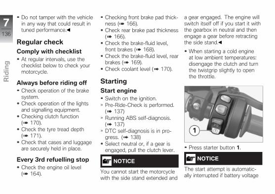
Do not tamper with the vehiclein any way that could result intuned performance.
Regular checkComply with checklist
At regular intervals, use thechecklist below to check yourmotorcycle.
Always before riding offCheck operation of the brakesystem.Check operation of the lightsand signalling equipment.Checking clutch function( 170).Check the tyre tread depth( 171).Check that cases and luggageare securely held in place.
Every 3rd refuelling stopCheck the engine oil level( 164).
Checking front brake pad thick-ness ( 166).Check rear brake pad thickness( 166).Check the brake-fluid level,front brakes ( 168).Check the brake-fluid level, rearbrakes ( 169).Check coolant level ( 170).
StartingStart engine
Switch on the ignition.Pre-Ride-Check is performed.( 137)Running ABS self-diagnosis.( 137)DTC self-diagnosis is in pro-gress. ( 138)Select neutral or, if a gear isengaged, pull the clutch lever.
NOTICE
You cannot start the motorcyclewith the side stand extended and
a gear engaged. The engine willswitch itself off if you start it withthe gearbox in neutral and thenengage a gear before retractingthe side stand.
When starting a cold engineat low ambient temperatures:disengage the clutch and turnthe twistgrip slightly to openthe throttle.
Press starter button 1.
NOTICE
The start attempt is automatic-ally interrupted if battery voltage
7136
z Rid
ing
is too low. Recharge the batterybefore you start the engine, oruse jump leads and a donor bat-tery to start.See the subsection on jumpstarting in "Maintenance" formore details.
The engine starts.Consult the troubleshootingchart below if the engine re-fuses to start. ( 212)
Pre-Ride-CheckAfter having switched on theignition, the instrument clustertests the ABS and ASC indic-ator and warning lights, the gen-eral warning light as well as theneedles. The logo appears onthe display during this process.
Phase 1The ABS indicator andwarning light shows.
General warning light lightsup yellow.
Phase 2The ABS indicator andwarning light shows.
The "General" warning lightshows red.
If the general warning light is notshown:
WARNING
Faulty "General" warninglight.No indication of malfunctions.
Check that the 'General' warn-ing light comes on, and that itshows red and yellow.
Have the fault rectified asquickly as possible by aspecialist workshop, preferablyan authorised BMW Motorraddealer.
ABS self-diagnosisThe operational readiness ofBMW Motorrad Integral ABS ischecked using self-diagnosis.Self-diagnosis starts automaticallywhen you switch on the ignition.
Phase 1Test of the diagnosis-compat-ible system components withthe vehicle at a standstill.
The ABS indicator andwarning light flashes.
Phase 2Test of the wheel-speedsensors as the vehiclepulls away from rest. Themotorcycle must reach a speedof at least 5 km⁄h in orderfor ABS self-diagnosis tocomplete.
The ABS indicator andwarning light flashes.
7137
z Rid
ing
ABS self-diagnosiscompleted
The ABS indicator and warninglight goes out.
If an indicator showing an ABSfault appears when ABS self-dia-gnosis completes:
You can continue to ride. Bearin mind that neither the ABSfunction nor the integral brak-ing function is available.Have the fault rectified asquickly as possible by aspecialist workshop, preferablyan authorised BMW Motorraddealer.
DTC self-diagnosisBMW Motorrad DTC performsself-diagnosis to check opera-tional readiness. Self-diagnosisis performed automatically whenyou switch on the ignition.
Phase 1Test of the diagnosis-compat-ible system components withthe vehicle at a standstill.
The DTC indicator lightflashes slowly.
Phase 2Test of the diagnosis-compat-ible system components whilethe motorcycle is on the move.The motorcycle must reach aspeed of at least 5 km⁄h withthe engine running in order forDTC self-diagnosis to com-plete.
The DTC indicator lightflashes slowly.
DTC self-diagnosiscompleted
The DTC symbol no longershows.
If an indicator showing an DTCfault appears when DTC self-diagnosis completes:
You can continue to ride. Bearin mind that the DTC functionis not available.Have the fault rectified asquickly as possible by aspecialist workshop, preferablyan authorised BMW Motorraddealer.
Running inEngine
Until the first running-in check,vary the throttle opening andengine-speed range frequently;avoid riding at constant enginerpm for prolonged periods.Select a route with plenty ofturns and minor hills, but avoidmotorways where possible.Comply with the rpm limits forrunning in.
7138
z Rid
ing
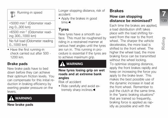
Running-in speed
<5000 min-1 (Odometer read-ing 0...300 km)
<6500 min-1 (Odometer read-ing 300...1000 km)
No full load (Odometer reading0...1000 km)
Have the first running-incheck carried out after 500 -1200 km.
Brake padsNew brake pads have to beddown before they can achievetheir optimum friction levels. Youcan compensate for this initial re-duction in braking efficiency byexerting greater pressure on thelevers.
WARNING
New brake pads
Longer stopping distance, risk ofaccident
Apply the brakes in goodtime.
TyresNew tyres have a smooth sur-face. This must be roughened byriding in a restrained manner atvarious heel angles until the tyresare run in. This running in pro-cedure is essential if the tyres areto achieve maximum grip.
WARNING
New tyres losing grip on wetroads and at extreme bankanglesRisk of accident
Ride carefully and avoid ex-tremely sharp inclines.
BrakesHow can stoppingdistance be minimised?Each time the brakes are applied,a load distribution shift takesplace with the load shifting for-ward from the rear to the frontwheel. The sharper the vehicledecelerates, the more load isshifted to the front wheel. Thehigher the wheel load, the morebraking force can be transmittedwithout the wheel locking.To optimise stopping distance,apply the front brakes rapidly andkeep on increasing the force youapply to the brake lever. Thismakes the best possible use ofthe dynamic increase in load atthe front wheel. Remember topull the clutch at the same time.In the "panic braking situations"that are trained so frequently,braking force is applied as rap-idly as possible and with the
7139
z Rid
ing
rider's full force applied to thebrake levers; under these circum-stances, the dynamic shift in loaddistribution cannot keep pacewith the increase in decelerationand the tyres cannot transmit thefull braking force to the surfaceof the road.The BMW Motorrad Integral ABSprevents the front wheel fromlocking up.
Hazard brakingIf you brake sharply from a speedin excess of 50 km⁄h, the brakelight flashes rapidly as an addi-tional warning for road users be-hind you.The hazard warning lights sys-tem switches on if you brake tobelow 15 km⁄h in this process.The hazard warning lights systemautomatically switches off from aspeed of 20 km⁄h.
Descending mountainpasses
WARNING
Braking only with the rearbrake on mountain descents.Brake fade. Destruction of thebrakes due to overheating.
Use the front brake and utiliseengine braking.
DANGER
Riding with overheatedbrakesRisk of accident due to failure ofbrakes
Adapt your riding style accord-ingly.Avoid frequent braking by usingthe engine brake.
WARNING
Failure to observe serviceintervals
Risk of accidentObserve the valid service inter-vals for brakes.
Wet and dirty brakesWetness and dirt on the brakediscs and the brake pads dimin-ish braking efficiency.Delayed braking action or poorbraking efficiency must bereckoned with in the followingsituations:
Riding in the rain or throughpuddles of water.After the motorcycle has beenwashed.Riding on salted or grittedroads.After work has been carried onthe brakes, due to traces of oilor grease.Riding on dirt-covered surfacesor off-road.
7140
z Rid
ing
WARNING
Wetness and dirt result indiminished braking efficiencyRisk of accident
Apply the brakes lightly whileriding to remove wetness anddirt, or dismount and clean thebrakes.Think ahead and brake in goodtime until full braking efficiencyis restored.
ABS ProPhysical limits applicable tomotorcycling
WARNING
Braking when corneringRisk of crash despite ABS Pro
Invariably, it remains the rider'sresponsibility to adapt ridingstyle to riding conditions.
Do not take risks that wouldnegate the additional safetyoffered by this system.
ABS Pro is available in all ridingmodes.
Possibility of a fall notprecludedAlthough ABS Pro provides therider with valuable assistance andconstitutes a huge advance insafety for braking with the mo-torcycle banked for cornering, itcannot under any circumstancesbe considered as redefining thephysical limits that apply to mo-torcycling. It is still possible forthese limits to be overshot dueto misjudgement or rider error. Inextreme cases this can result in acrash.
Use on public roadsABS Pro helps make the mo-torcycle even safer for riding onpublic roads. When the brakes
are applied because of an un-foreseen hazard when the mo-torcycle is banked for cornering,within the physical limits that ap-ply to motorcycling the systemprevents the wheels from lockingand skidding away.
NOTICE
ABS Pro was not developed toenhance individual braking per-formance with the motorcyclebanked into corners.
Parking yourmotorcycleSide stand
Switch off the engine.
ATTENTION
Poor ground underneath thestandRisk of damage to parts if vehicletopples
7141
z Rid
ing
Always check that the groundunder the stand is level andfirm.
Extend the side stand and propthe motorcycle on the stand.
ATTENTION
Additional weight placingstrain on the side standRisk of damage to parts if vehicletopples
Do not sit or lean on thevehicle while it is propped onthe side stand.
If the camber of the roadwaypermits, turn the handlebars allthe way to the left.On a gradient, the motorcycleshould always face uphill; se-lect 1st gear.
Centre standSwitch off the engine.
ATTENTION
Poor ground underneath thestandRisk of damage to parts if vehicletopples
Always check that the groundunder the stand is level andfirm.
ATTENTION
Centre stand retracts due tosevere movementsRisk of damage to parts if vehicletopples
Do not lean or sit on thevehicle with the centre standextended.
Extend the centre stand and liftthe motorcycle on to the stand.
RefuellingFuel gradeRequirementTo ensure optimal fuel consump-tion, fuel should be sulphur-freeor as low-sulphur as possible.
ATTENTION
Engine operation with leadedfuelDamage to catalytic converter
Do not attempt to run thevehicle on leaded fuel or fuelwith metallic additives (e.g.manganese or iron).
Fuels with a maximum ethanolcontent of 10%, that is E10,can be used.
7142
z Rid
ing
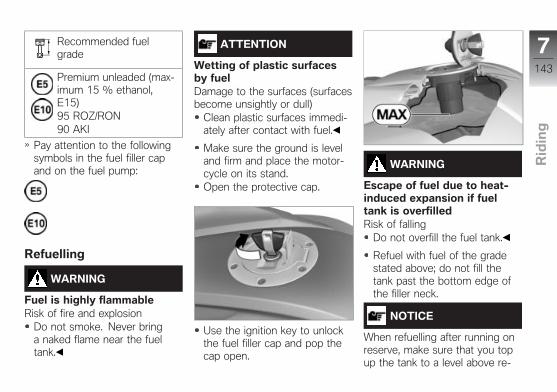
Recommended fuelgrade
Premium unleaded (max-imum 15 % ethanol,E15)95 ROZ/RON90 AKI
Pay attention to the followingsymbols in the fuel filler capand on the fuel pump:
Refuelling
WARNING
Fuel is highly flammableRisk of fire and explosion
Do not smoke. Never bringa naked flame near the fueltank.
ATTENTION
Wetting of plastic surfacesby fuelDamage to the surfaces (surfacesbecome unsightly or dull)
Clean plastic surfaces immedi-ately after contact with fuel.
Make sure the ground is leveland firm and place the motor-cycle on its stand.Open the protective cap.
Use the ignition key to unlockthe fuel filler cap and pop thecap open.
WARNING
Escape of fuel due to heat-induced expansion if fueltank is overfilledRisk of falling
Do not overfill the fuel tank.
Refuel with fuel of the gradestated above; do not fill thetank past the bottom edge ofthe filler neck.
NOTICE
When refuelling after running onreserve, make sure that you topup the tank to a level above re-
7143
z Rid
ing
serve, so that the new level isdetected and the fuel reserve in-dicator light is switched off.
Usable fuel capacity
approx. 26.5 l
Reserve fuel
approx. 4 l
Press the fuel tank cap downfirmly to close.Remove the ignition key andclose the protective cap.
Refuellingwith Keyless Ride OE
RequirementThe steering lock is disengaged.
WARNING
Fuel is highly flammable
Risk of fire and explosionDo not smoke. Never bringa naked flame near the fueltank.
ATTENTION
Wetting of plastic surfacesby fuelDamage to the surfaces (surfacesbecome unsightly or dull)
Clean plastic surfaces immedi-ately after contact with fuel.
Make sure the ground is leveland firm and place the motor-cycle on its centre stand.with Keyless Ride OE
Switch off the ignition ( 64).
NOTICE
The fuel filler cap can be openedwithin the defined waiting timeafter the ignition has beenswitched off, without the radio-
operated key being withinrange.
Waiting time for openingthe fuel filler cap
2 min
There are two variant waysof opening the fuel filler cap:Within the waiting time.After the waiting time has ex-pired.
Version 1with Keyless Ride OE
RequirementWithin the waiting time
7144
z Rid
ing
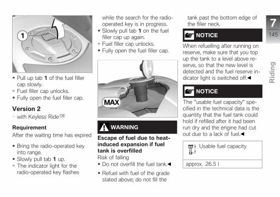
Pull up tab 1 of the fuel fillercap slowly.Fuel filler cap unlocks.Fully open the fuel filler cap.
Version 2with Keyless Ride OE
RequirementAfter the waiting time has expired
Bring the radio-operated keyinto range.Slowly pull tab 1 up.The indicator light for theradio-operated key flashes
while the search for the radio-operated key is in progress.Slowly pull tab 1 on the fuelfiller cap up again.Fuel filler cap unlocks.Fully open the fuel filler cap.
WARNING
Escape of fuel due to heat-induced expansion if fueltank is overfilledRisk of falling
Do not overfill the fuel tank.
Refuel with fuel of the gradestated above; do not fill the
tank past the bottom edge ofthe filler neck.
NOTICE
When refuelling after running onreserve, make sure that you topup the tank to a level above re-serve, so that the new level isdetected and the fuel reserve in-dicator light is switched off.
NOTICE
The "usable fuel capacity" spe-cified in the technical data is thequantity that the fuel tank couldhold if refilled after it had beenrun dry and the engine had cutout due to a lack of fuel.
Usable fuel capacity
approx. 26.5 l
7145
z Rid
ing

Reserve fuel
approx. 4 l
Press down firmly on the fillercap of the fuel tank.The fuel filler cap engages withan audible click.The fuel filler cap locks auto-matically when the waiting timeexpires.The engaged fuel filler caplocks immediately when yousecure the steering lock orswitch on the ignition.
Securing motorcyclefor transportation
Make sure that all componentsthat might come into contactwith straps used to secure themotorcycle are adequately pro-tected against scratching. Use
adhesive tape or soft cloths, forexample, for this purpose.
ATTENTION
Vehicle topples to side whenbeing lifted on to standRisk of damage to parts if vehicletopples
Secure the vehicle to prevent ittoppling, preferably with the as-sistance of a second person.
Push the motorcycle on to thetransportation flat and hold it inposition: do not place it on theside stand or centre stand.
ATTENTION
Routing of tensioning strapsnot in compliance with cor-rect procedureDamage to brake lines, Bowdencables, bearings and trim panels
Carefully route retaining straps.Use a cloth to protect paintedcomponents from scratches.
Guide the tensioning strapsthrough the front suspensionon the left and right and thentighten towards the bottom.
7146
z Rid
ing
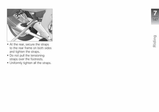
At the rear, secure the strapsto the rear frame on both sidesand tighten the straps.Do not pull the tensioningstraps over the footrests.Uniformly tighten all the straps.
7147
z Rid
ing

7148
z Rid
ing
Engineering details
General instructions . . . . . . . . . . . . . . . . 150
Antilock Brake System (ABS) . . . . . . 150
Dynamic Traction Control(DTC) . . . . . . . . . . . . . . . . . . . . . . . . . . . . . . 153
Electronic Suspension Adjustment(DESA) . . . . . . . . . . . . . . . . . . . . . . . . . . . . 155
Riding mode . . . . . . . . . . . . . . . . . . . . . . . 155
Tyre pressure monitoring(RDC) . . . . . . . . . . . . . . . . . . . . . . . . . . . . . . 157
Gear Shift Assistant . . . . . . . . . . . . . . . . 158
Hill Start Control . . . . . . . . . . . . . . . . . . . 159
Adaptive Headlight . . . . . . . . . . . . . . . . . 160
8149
z En
gin
ee
rin
g d
eta
ils

General instructionsTo find out more about engineer-ing, go to:bmw-motorrad.com/techno-logy
Antilock Brake System(ABS)Partially integral brakesYour motorcycle is equipped withpartially integral brakes. Bothfront and rear brakes are appliedwhen you pull the handbrakelever. The footbrake lever actsonly on the rear brake.While the brakes are slowing themotorcycle, the BMW MotorradIntegral ABS adapts braking-forcedistribution between front andrear brakes to suit the load onthe motorcycle.
ATTENTION
Attempted burn-out despiteIntegral braking functionDamage to rear brake and clutch
Do not burn out tyres.
How does ABS work?The amount of braking force thatcan be transferred to the roaddepends on factors hat includethe coefficient of friction of theroad surface. Loose stones, iceand snow or a wet road all havemuch lower coefficients of frictionthan a clean, dry asphalt surface.The lower the coefficient of fric-tion, the longer the braking dis-tance.If the rider increases brakingpressure to the extent that brak-ing force exceeds the maximumtransferrable limit, the wheelsstart to lock and the motorcycleloses its directional stability; a fallis imminent. Before this situation
can occur, ABS intervenes andadapts braking pressure to themaximum transferrable brakingforce, so the wheels continueto turn and directional stabilityis maintained irrespective of thecondition of the road surface.
What are the effects ofsurface irregularities?Humps and surface irregular-ities can cause the wheels tolose contact temporarily with theroad surface; if this happens thebraking force that can be trans-mitted to the road can drop tozero. If the brakes are appliedunder these circumstances theABS has to reduce braking forceto ensure that directional sta-bility is maintained when thewheels regain contact with theroad surface. At this instant theBMW Motorrad Integral ABSmust assume an extremely lowcoefficient of friction, so that the
8150
z En
gin
ee
rin
g d
eta
ils
wheels will continue to rotate un-der all imaginable circumstances,because this is the preconditionfor ensuring directional stability.As soon as is registers the ac-tual circumstances, the systemreacts instantly and adjusts brak-ing force accordingly to achieveoptimum braking.
What feedback does therider receive from theBMW Motorrad IntegralABS?If the ABS system has to reducebraking force on account of thecircumstances described above,vibration is perceptible throughthe handbrake lever.When the handbrake lever ispulled, brake pressure is alsobuilt up at the rear wheel bythe integral function. If thebrake pedal is depressed afterthe handbrake lever is pulled,the brake pressure built up
beforehand is perceptible ascounter-pressure sooner than isthe case when the brake pedal isdepressed either before or at thesame time as the brake lever ispulled.
Rear wheel liftEven under severe braking, ahigh level of tyre grip can meanthat the front wheel does notlock up until very late, if at all.Consequently, ABS does not in-tervene until very late, if at all.Under these circumstances therear wheel can lift off the ground,and the outcome can be a high-siding situation in which the mo-torcycle can flip over.
WARNING
Rear wheel lift due to severebrakingRisk of falling
When you brake sharply, bearin mind that ABS control can-
not always be relied on to pre-vent the rear wheel from liftingclear of the ground.
What is the designbaseline forBMW Motorrad IntegralABS?Within the limits imposed byphysics, the BMW Motorrad ABSensures directional stability onany surface.
At speeds above 4 km/h, withinthe limits imposed by physicsthe BMW Motorrad ABS canensure directional stabilityon any surface. Limitationsinherent to the design principlemean that at lower speeds theBMW Motorrad ABS cannotprovide optimum assistance onall surfaces.
8151
z En
gin
ee
rin
g d
eta
ils
The system is not optimised forspecial requirements that applyunder extreme competitive situ-ations off-road or on the track.
Special situationsThe speeds of the front and rearwheels are compared as onemeans of detecting a wheel'sincipient tendency to lock. Ifthe system registers implaus-ible values for a lengthy periodthe ABS function is deactivatedfor safety reasons and an ABSfault message is issued. Self-dia-gnosis has to complete beforefault messages can be issued.In addition to problems with theBMW Motorrad Integral ABS,exceptional riding conditions canlead to a fault message beingissued.Exceptional ridingconditions:
Heating up with the motorcycleon the centre stand or an auxil-
iary stand, engine idling or witha gear engaged.Rear wheel locked by the en-gine brake for a lengthy period,for example while descendingon a loose surface.
If a fault message is issued onaccount of exceptional ridingconditions as outlined above, youcan reactivate the ABS functionby switching the ignition off andon again.
What significancedevolves on regularmaintenance?
WARNING
Brake system not regularlyserviced.Risk of accident
In order to ensure that the ABSis always maintained in op-timum condition, it is essen-tial for you to comply strictly
with the specified inspectionintervals.
Reserves for safetyThe potentially shorter brakingdistances which BMW MotorradIntegral ABS permits must not beused as an excuse for carelessriding. ABS is primarily a meansof ensuring a safety margin ingenuine emergencies.Take care when cornering! Whenyou apply the brakes on a corner,the motorcycle's weight andmomentum take over and evenBMW Motorrad Integral ABS isunable to counteract their effects.
Evolution of ABS toABS ProUntil now, the BMW MotorradABS helped ensure a very highdegree of safety for brakingwith the motorcycle uprightand travelling in a straight line.Now ABS Pro offers enhanced
8152
z En
gin
ee
rin
g d
eta
ils

safety for braking in cornersas well. ABS Pro prevents thewheels from locking even undersharp braking. ABS Pro reducesabrupt changes in steeringforce, particularly in panic-braking situations, counteractingthe vehicle's otherwise naturalbut undesirable tendency tostraighten up.
ABS interventionTechnically speaking, dependingon the riding situation ABS Proadapts ABS intervention to themotorcycle's bank angle. Signalsfor rate of roll and rate of yawand lateral acceleration are usedto calculate bank angle. Thesesignals come from the angularrate sensor, an integral compon-ent of Dynamic Traction ControlDTC and Dynamic ESA.As the motorcycle is heeled overmore and more as it banks intoa corner, an increasingly strict
limit is imposed on the brake-pressure gradient for the start ofbrake application. This slows thebuild-up of brake pressure to acorresponding degree. Addition-ally, pressure modulation is moreuniform across the range of ABSintervention.
Advantages for the riderThe advantages of ABS Pro forthe rider are sensitive responseand high braking and directionalstability combined with best-casedeceleration of the motorcycle,even when cornering.
Dynamic TractionControl (DTC)How does DTC work?The BMW Motorrad DTC com-pares the speed of rotation of thefront wheel and the rear wheel.The differential is used to com-pute slip as a measure of the
reserves of stability available atthe rear wheel. If slip exceeds acertain limit, the engine controlintervenes and adapts the enginetorque accordingly.
WARNING
Risky ridingRisk of accident despite DTC
Invariably, the rider bears re-sponsibility for assessing roadand traffic conditions and ad-opting his or her style of ridingaccordingly.Do not take risks that wouldnegate the additional safetyoffered by this system.
What is the designbaseline forBMW Motorrad DTC?BMW Motorrad DTC is designedas an assistant system for therider and for use on public roads.The extent to which the rider af-
8153
z En
gin
ee
rin
g d
eta
ils
fects DTC control can be consid-erable (weight shifts when cor-nering, items of luggage loose onthe motorcycle), especially whenstyle of riding takes rider and ma-chine close to the limits imposedby physics.The system is not optimised forspecial requirements that applyunder extreme competitive situ-ations off-road or on the track.You have the option of deactiv-ating the BMW Motorrad DTCsystem for these circumstances.
WARNING
Risky ridingRisk of accident despite DTC
Invariably, the rider bears re-sponsibility for assessing roadand traffic conditions and ad-opting his or her style of ridingaccordingly.Do not take risks that wouldnegate the additional safetyoffered by this system.
Special situationsIn accordance with the laws ofphysics, the ability to accelerateis restricted more and more asthe angle of heel increases. Con-sequently, there can be a per-ceptible reduction in accelerationout of very tight bends.
The speeds of the front and rearwheels are compared and theangle of heel taken into accountas one means of detecting therear wheel's incipient tendency tospin or slip sideways. If the elec-tronic processor receives valuesthat it considers implausible overa lengthy period, a dummy valueis used for the angle of heel orthe DTC function is switchedoff. Under these circumstances,the indicator for a DTC fault isdisplayed. Self-diagnosis has tocomplete before fault messagescan be issued.
The BMW Motorrad DTC canissue an error message underthe exceptional riding conditionsoutlined below.Exceptional ridingconditions:
Riding for a lengthy period withthe front wheel lifted off theground (wheelie) with DTC de-activated.Rear wheel rotating with thevehicle held stationary by ap-plying the front brake (burn-out).Heating up with the motorcycleon an auxiliary stand, in neutralor with a gear engaged.
If the front wheel lifts clear of theground under severe accelera-tion, the DTC reduces enginetorque until the front wheel re-gains contact with the ground.Under these circumstances,BMW Motorrad recommendsrolling the throttle slightly closed
8154
z En
gin
ee
rin
g d
eta
ils
so as to restore stability with theleast possible delay.
When riding on a slippery sur-face, never snap the throttletwistgrip fully closed withoutpulling the clutch at the sametime. Engine braking torque cancause the rear wheel to skid, witha corresponding loss of stability.The BMW Motorrad DTC is un-able to control a situation of thisnature.
Electronic SuspensionAdjustment (DESA)Possible settingsDynamic ESA enables youto adjust your motorcycle'ssuspension to suit the load andthe surface conditions.By interpreting ride height sensorsignals, Dynamic ESA detectsmovements in the chassis andsuspension and responds by ad-justing the damping valves. The
chassis and suspension will thusbe adapted to the characteristicsof the terrain.The DYNAMIC setting enablesyou to set the damping to amore sporty setup than thatoffered by ROAD, which is thebasic setting.The suspension setting dependson the riding mode selected.The damping defined by the rid-ing mode can be changed by therider.Dynamic ESA calibrates itself atregular intervals when station-ary with the engine running toensure the correct operatingprinciple of the system. Dur-ing this calibration, chassis andsuspension adjustment is notpossible.
Riding modeSelectionThree riding modes enable themotorcycle's characteristics toadapt to the prevailing weatherconditions, the road and traffic,and the rider's style of riding:
RAINROADDYNAMIC
Each of these modes producesperceptible differences in theway the motorcycle behaves.DTC can be switched off in eachmode; the explanations below in-variably refer to conditions withthe system switched ON. Themode last selected is automatic-ally reactivated after the ignitionhas been switched off and thenon again.The basic rule is: the sportierthe mode you select, the moredirectly can you tap into the en-gine's reserves of power. At the
8155
z En
gin
ee
rin
g d
eta
ils
same time, the level of rider as-sistance that the DTC systemoffers decreases accordingly.Consequently, you must alwaysbear the following in mind withregard to your selection of a ridemode: The sportier the setting,the greater the challenge to yourriding skill!
RAINThe engine's full power is notmade available. Power increasewhen you open the throttle isreserved, engine response is cor-respondingly soft.The DTC system intervenes earlyenough to prevent the rear wheelfrom spinning. On road surfaceswith high to medium grip (dryand wet asphalt to dry cobble-stones) the vehicle remains verystable; movements of the tail areclearly perceptible only on slip-pery road surfaces (wet bitumenor wet cobblestones).
ROADThe engine's full power isavailable in this mode. Powerincrease when you open thethrottle is more direct than inRAIN mode, the engine respondsmore rapidly.DTC system intervention is laterthan in RAIN mode. On roadsurfaces with high to mediumgrip (dry and wet asphalt to drycobblestones) the motorcycle re-mains stable. Slight rear-wheeldrift is perceptible. Movementsof the tail are clearly perceptibleon slippery road surfaces (wetbitumen or wet cobblestones).
DYNAMICThe DYNAMIC mode is the spor-tiest mode.Power increase and engine re-sponse are the same as in ROADmode. Response to rider input,however, is considerably moredirect.
DTC system intervention is evenlater, which means that even ondry asphalt drifting is possibleunder sharp acceleration whencornering.
Mode changesThe engine control and DynamicTraction Control functions canonly be changed if no drivetorque applies to the rear wheel.In order to achieve this state,
The motorcycle must be ata standstill with the ignitionswitched on
orThe throttle grip must be in thefully closed position.
The desired riding mode is ini-tially preselected. The modechange does not take place untilthe systems in question are all inthe appropriate state.The selection menu does notdisappear from the display un-
8156
z En
gin
ee
rin
g d
eta
ils
til the mode change has takenplace.
Tyre pressuremonitoring (RDC)
with tyre pressure control(RDC)OE
FunctionA sensor integrated into eachtyre measures the air tempera-ture and the air pressure insidethe tyre and transmits this in-formation to the control unit.Each sensor has a switch thatdoes not enable transmissionof the measured values untilthe motorcycle has acceleratedto about 30 km⁄h. The displayshows for each tyre untilthe tyre-pressure signal isreceived for the first time. Thesensors continue to transmitthe measured-value signals forapproximately 15 minutes afterthe vehicle comes to a stop.
An error message is issued ifwheels without sensors are fit-ted to a vehicle equipped with anRDC control unit.
TemperaturecompensationTyre pressure is a temperature-sensitive variable: pressure in-creases as tyre temperature risesand decreases as tyre temper-ature drops. Tyre temperaturedepends on ambient tempera-ture, on the style of riding andthe duration of the ride.The tyre-pressure readingsshown by the multifunctiondisplay are temperature-compensated; the reference tyretemperature for these readingsis always 20 °C. The gauges onservice station air lines do notcompensate for temperature.The tyre pressure recordeddepends on tyre temperature.In most instances, therefore,
these gauge readings will nottally with the pressures shown bythe multifunction display. Thewarmer the tyres, the more thetester value exceeds the displayvalue.
Pressure adaptationCompare the RDC readingson the multifunction displaywith the value in the table onthe inside cover of the Rider'sManual. Then use the air line tocompensate for the differencebetween the RDC reading andthe value in the table.
Example: According to theRider's Manual, tyre pressureshould be 2.9 bar, but thereading in the multifunctiondisplay is 2.7 bar, so pressure islow by 0.2 bar. The gauge onthe air line shows 2.5 bar. Youmust now increase tyre pressureby the 0.2 bar differencebetween the value in the table
8157
z En
gin
ee
rin
g d
eta
ils
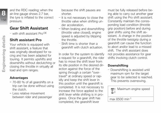
and the RDC reading; when theair-line gauge shows 2.7 bar,the tyre is inflated to the correctpressure.
Gear Shift Assistantwith shift assistant Pro OE
Shift assistant ProYour vehicle is equipped withshift assistant, a feature thatwas originally developed for ra-cing and has been adapted fortouring. It permits upshifts anddownshifts without declutching orclosing the throttle in virtually allload and rpm ranges.
Advantages70-80 % of all gearshifts on atrip can be done without usingthe clutch.Less relative movementbetween rider and passenger
because the shift pauses areshorter.It is not necessary to close thethrottle valve when shifting un-der acceleration.When braking and downshifting(throttle valve closed), enginespeed is adjusted by blippingthe throttle.Shift time is shorter than agearshift with clutch actuation.
In order for the system to identifya request for a gearshift, the riderhas to move the shift lever fromits idle position in the desired dir-ection against the force of thespring through a certain "over-travel" at ordinary speed or rap-idly and keep the shift lever inthis position until the gearshift iscompleted. It is not necessary toincrease the force applied to theshift lever while shifting is in pro-gress. Once the gear shift hascompleted, the gearshift lever
must be fully released before be-ing able to carry out another gearshift using the Pro shift assistant.Constantly maintain the corres-ponding load condition (throttlegrip position) before and duringgear shifts using the shift as-sistant. A change in the positionof the throttle twistgrip during agearshift can cause the functionto abort and/or lead to a missedshift. The shift assistant doesnot provides assistance for gearshifts involving clutch control.
DownshiftingDownshifting is assisted untilmaximum rpm for the targetgear to be selected is reached.This prevents overrevving.
Maximum engine speed
max 8500 min-1
8158
z En
gin
ee
rin
g d
eta
ils
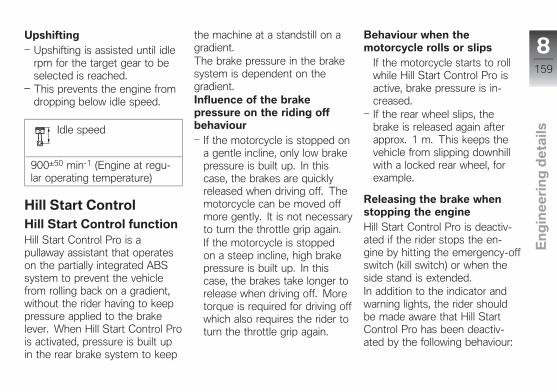
UpshiftingUpshifting is assisted until idlerpm for the target gear to beselected is reached.This prevents the engine fromdropping below idle speed.
Idle speed
900±50 min-1 (Engine at regu-lar operating temperature)
Hill Start ControlHill Start Control functionHill Start Control Pro is apullaway assistant that operateson the partially integrated ABSsystem to prevent the vehiclefrom rolling back on a gradient,without the rider having to keeppressure applied to the brakelever. When Hill Start Control Prois activated, pressure is built upin the rear brake system to keep
the machine at a standstill on agradient.The brake pressure in the brakesystem is dependent on thegradient.Influence of the brakepressure on the riding offbehaviour
If the motorcycle is stopped ona gentle incline, only low brakepressure is built up. In thiscase, the brakes are quicklyreleased when driving off. Themotorcycle can be moved offmore gently. It is not necessaryto turn the throttle grip again.If the motorcycle is stoppedon a steep incline, high brakepressure is built up. In thiscase, the brakes take longer torelease when driving off. Moretorque is required for driving offwhich also requires the rider toturn the throttle grip again.
Behaviour when themotorcycle rolls or slips
If the motorcycle starts to rollwhile Hill Start Control Pro isactive, brake pressure is in-creased.If the rear wheel slips, thebrake is released again afterapprox. 1 m. This keeps thevehicle from slipping downhillwith a locked rear wheel, forexample.
Releasing the brake whenstopping the engineHill Start Control Pro is deactiv-ated if the rider stops the en-gine by hitting the emergency-offswitch (kill switch) or when theside stand is extended.In addition to the indicator andwarning lights, the rider shouldbe made aware that Hill StartControl Pro has been deactiv-ated by the following behaviour:
8159
z En
gin
ee
rin
g d
eta
ils
Brake warning joltThe brake is released brieflyand reactivated immediately.This creates a jolt which therider feels.The partial integral ABS brakesystem sets a speed of approx.3 km/h.The rider must brake the mo-torcycle manually.After two minutes, or when thebrake is actuated, Hill StartControl Pro is completely de-activated.
NOTICE
The holding pressure is releasedimmediately without a brakewarning jolt as soon as theignition is switched off.
Adaptive Headlightwith adaptive head light OE
How does the adaptivecornering headlight work?The standard low-beam unit inthe main headlight consists ofa centrally positioned, movablexenon projection module with re-flector. Ride height sensors onfront and rear suspension supplydata for permanent beam throwadjustment. While the motor-cycle is moving straight ahead,pitch compensation keeps thethrow of the headlight beam con-stantly in the optimum, presetrange, regardless of ride and loadstate.In addition, the adaptive headlighthas a servomotor that enables aswivelling action of the reflector,which is normally static. Thereflector is turned about an axisthat varies with the bank angle,compensating for the vehicle's
angle of lean. Along with pitchcompensation, therefore, thethrow of the low-beam headlightalso compensates for the rider'schosen bank angle throughcorners. The two movementsare superimposed, so as themotorcycle is steered througha bend the headlight beam isdirected into the bend for betterillumination of the road ahead.
8160
z En
gin
ee
rin
g d
eta
ils
Maintenance
General instructions . . . . . . . . . . . . . . . . 162
Toolkit . . . . . . . . . . . . . . . . . . . . . . . . . . . . . 162
Front-wheel stand . . . . . . . . . . . . . . . . . 162
Engine oil . . . . . . . . . . . . . . . . . . . . . . . . . . 164
Brake system . . . . . . . . . . . . . . . . . . . . . . 165
Clutch . . . . . . . . . . . . . . . . . . . . . . . . . . . . . 170
Coolant . . . . . . . . . . . . . . . . . . . . . . . . . . . . 170
Tyres . . . . . . . . . . . . . . . . . . . . . . . . . . . . . . 171
Rims and tyres . . . . . . . . . . . . . . . . . . . . . 171
Wheels . . . . . . . . . . . . . . . . . . . . . . . . . . . . 172
Lighting . . . . . . . . . . . . . . . . . . . . . . . . . . . . 179
Jump-starting . . . . . . . . . . . . . . . . . . . . . . 185
Battery . . . . . . . . . . . . . . . . . . . . . . . . . . . . . 186
Fuses . . . . . . . . . . . . . . . . . . . . . . . . . . . . . . 190
Diagnostic connector . . . . . . . . . . . . . . 191
9161
z Ma
inte
na
nc
e

General instructionsThe Maintenance chapter de-scribes straightforward proced-ures for checking and replacingcertain wear parts.Special tightening torques are lis-ted as applicable. The tighteningtorques for the threaded fasten-ers on your vehicle are listed inthe section entitled "Technicaldata".You will find information on moreextensive maintenance and repairwork in the Repair Manual onDVD for your vehicle, which isavailable from your authorisedBMW Motorrad dealer.
Some of the work calls for spe-cial tools and a thorough know-ledge of the technology involved.If you are in doubt consult aspecialist workshop, preferablyyour authorised BMW Motorraddealer.
ToolkitStandard toolkit
1 Screwdriver handle2 Reversible screwdriver
bladePhillips PH1 and Torx T25
3 Torx wrench, T25/T30T25 on short end, T30 onlong end
Replacing bulb forhigh-beam headlight( 179).Disengage the numberplate carrier.
Front-wheel standInstalling front-wheelstand
ATTENTION
Use of the BMW Motorradfront-wheel stand withoutaccompanying use of centrestand or auxiliary standRisk of damage to parts if vehicletopples
Place the motorcycle on itscentre stand or another auxili-ary stand before lifting the frontwheel with the BMW Motorradfront-wheel stand.
Use basic stand with tool num-ber (83 30 0 402 241) in com-bination with front-wheel ad-apter (83 30 0 402 243).Make sure the ground is leveland firm and place the motor-cycle on its centre stand.
9162
z Ma
inte
na
nc
e
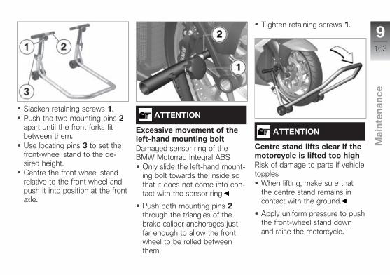
Slacken retaining screws 1.Push the two mounting pins 2apart until the front forks fitbetween them.Use locating pins 3 to set thefront-wheel stand to the de-sired height.Centre the front wheel standrelative to the front wheel andpush it into position at the frontaxle.
ATTENTION
Excessive movement of theleft-hand mounting boltDamaged sensor ring of theBMW Motorrad Integral ABS
Only slide the left-hand mount-ing bolt towards the inside sothat it does not come into con-tact with the sensor ring.
Push both mounting pins 2through the triangles of thebrake caliper anchorages justfar enough to allow the frontwheel to be rolled betweenthem.
Tighten retaining screws 1.
ATTENTION
Centre stand lifts clear if themotorcycle is lifted too highRisk of damage to parts if vehicletopples
When lifting, make sure thatthe centre stand remains incontact with the ground.
Apply uniform pressure to pushthe front-wheel stand downand raise the motorcycle.
9163
z Ma
inte
na
nc
e
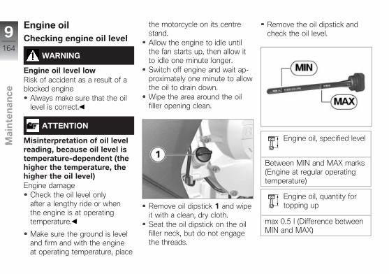
Engine oilChecking engine oil level
WARNING
Engine oil level lowRisk of accident as a result of ablocked engine
Always make sure that the oillevel is correct.
ATTENTION
Misinterpretation of oil levelreading, because oil level istemperature-dependent (thehigher the temperature, thehigher the oil level)Engine damage
Check the oil level onlyafter a lengthy ride or whenthe engine is at operatingtemperature.
Make sure the ground is leveland firm and with the engineat operating temperature, place
the motorcycle on its centrestand.Allow the engine to idle untilthe fan starts up, then allow itto idle one minute longer.Switch off engine and wait ap-proximately one minute to allowthe oil to drain down.Wipe the area around the oilfiller opening clean.
Remove oil dipstick 1 and wipeit with a clean, dry cloth.Seat the oil dipstick on the oilfiller neck, but do not engagethe threads.
Remove the oil dipstick andcheck the oil level.
Engine oil, specified level
Between MIN and MAX marks(Engine at regular operatingtemperature)
Engine oil, quantity fortopping up
max 0.5 l (Difference betweenMIN and MAX)
9164
z Ma
inte
na
nc
e
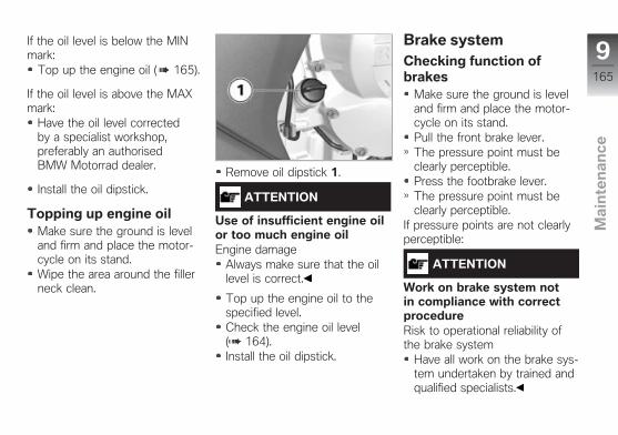
If the oil level is below the MINmark:
Top up the engine oil ( 165).
If the oil level is above the MAXmark:
Have the oil level correctedby a specialist workshop,preferably an authorisedBMW Motorrad dealer.
Install the oil dipstick.
Topping up engine oilMake sure the ground is leveland firm and place the motor-cycle on its stand.Wipe the area around the fillerneck clean.
Remove oil dipstick 1.
ATTENTION
Use of insufficient engine oilor too much engine oilEngine damage
Always make sure that the oillevel is correct.
Top up the engine oil to thespecified level.Check the engine oil level( 164).Install the oil dipstick.
Brake systemChecking function ofbrakes
Make sure the ground is leveland firm and place the motor-cycle on its stand.Pull the front brake lever.The pressure point must beclearly perceptible.Press the footbrake lever.The pressure point must beclearly perceptible.
If pressure points are not clearlyperceptible:
ATTENTION
Work on brake system notin compliance with correctprocedureRisk to operational reliability ofthe brake system
Have all work on the brake sys-tem undertaken by trained andqualified specialists.
9165
z Ma
inte
na
nc
e
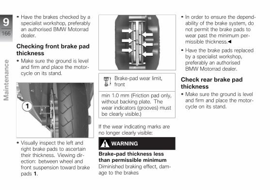
Have the brakes checked by aspecialist workshop, preferablyan authorised BMW Motorraddealer.
Checking front brake padthickness
Make sure the ground is leveland firm and place the motor-cycle on its stand.
Visually inspect the left andright brake pads to ascertaintheir thickness. Viewing dir-ection: between wheel andfront suspension toward brakepads 1.
Brake-pad wear limit,front
min 1.0 mm (Friction pad only,without backing plate. Thewear indicators (grooves) mustbe clearly visible.)
If the wear indicating marks areno longer clearly visible:
WARNING
Brake-pad thickness lessthan permissible minimumDiminished braking effect, dam-age to the brakes
In order to ensure the depend-ability of the brake system, donot permit the brake pads towear past the minimum per-missible thickness.
Have the brake pads replacedby a specialist workshop,preferably an authorisedBMW Motorrad dealer.
Check rear brake padthickness
Make sure the ground is leveland firm and place the motor-cycle on its stand.
9166
z Ma
inte
na
nc
e

Visually inspect the brake padsto ascertain their thickness.Viewing direction: from belowtoward brake pads 1.
Brake-pad wear limit,rear
min 1.0 mm (Friction pad only,without backing plate. Thewear indicators (grooves) musthave not been reached.)
If the wear indicating mark is nolonger visible:
WARNING
Brake-pad thickness lessthan permissible minimumDiminished braking effect, dam-age to the brakes
In order to ensure the depend-ability of the brake system, donot permit the brake pads towear past the minimum per-missible thickness.
Have the brake pads replacedby a specialist workshop,preferably an authorisedBMW Motorrad dealer.
9167
z Ma
inte
na
nc
e
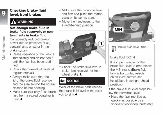
Checking brake-fluidlevel, front brakes
WARNING
Not enough brake fluid inbrake fluid reservoir, or con-taminants in brake fluidConsiderably reduced brakingpower due to presence of air,contaminants or water in thebrake system
Cease operation of the vehicleimmediately and do not ride ituntil the fault has been recti-fied.Check the brake-fluid levels atregular intervals.Always make sure that thelid of the brake fluid reservoirand the area around the lid arecleaned before opening.Make sure that only fresh brakefluid from a sealed container isused.
Make sure the ground is leveland firm and place the motor-cycle on its centre stand.Move the handlebars to thestraight-ahead position.
Check the brake fluid level inbrake fluid reservoir for frontwheel brake 1.
NOTICE
Wear of the brake pads causesthe brake fluid level in the reser-voir to sink.
Brake fluid level, front
Brake fluid, DOT4
It is impermissible for thebrake fluid level to drop belowthe MIN mark. (Brake fluidtank is horizontal, vehicleon an even surface andhandlebars in straight-aheadposition.)
If the brake fluid level drops be-low the permitted level:
Have the fault rectified asquickly as possible by aspecialist workshop, preferably
9168
z Ma
inte
na
nc
e

an authorised BMW Motorraddealer.
Checking brake-fluidlevel, rear brakes
WARNING
Not enough brake fluid inbrake fluid reservoir, or con-taminants in brake fluidConsiderably reduced brakingpower due to presence of air,contaminants or water in thebrake system
Cease operation of the vehicleimmediately and do not ride ituntil the fault has been recti-fied.Check the brake-fluid levels atregular intervals.Always make sure that thelid of the brake fluid reservoirand the area around the lid arecleaned before opening.
Make sure that only fresh brakefluid from a sealed container isused.
Make sure the ground is leveland firm and place the motor-cycle on its centre stand.
Check the brake fluid level inbrake fluid reservoir for rearwheel brake 1.
NOTICE
Wear of the brake pads causesthe brake fluid level in the reser-voir to sink.
Brake fluid level, rear
Brake fluid, DOT4
It is impermissible for thebrake fluid level to drop belowthe MIN mark. (Brake-fluidreservoir horizontal, motorcycleupright.)
If the brake fluid level drops be-low the permitted level:
Have the fault rectified asquickly as possible by aspecialist workshop, preferably
9169
z Ma
inte
na
nc
e
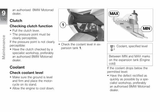
an authorised BMW Motorraddealer.
ClutchChecking clutch function
Pull the clutch lever.The pressure point must beclearly perceptible.
If the pressure point is not clearlyperceptible:
Have the clutch checked by aspecialist workshop, preferablyan authorised BMW Motorraddealer.
CoolantCheck coolant level
Make sure the ground is leveland firm and place the motor-cycle on its stand.Allow the engine to cool down.
Check the coolant level in ex-pansion tank 1.
Coolant, specified level
Between MIN and MAX markson the expansion tank (Enginecold)
If the coolant drops below thepermitted level:
Have the defect rectified asquickly as possible by a spe-cialist workshop, preferablyan authorised BMW Motorraddealer.
9170
z Ma
inte
na
nc
e
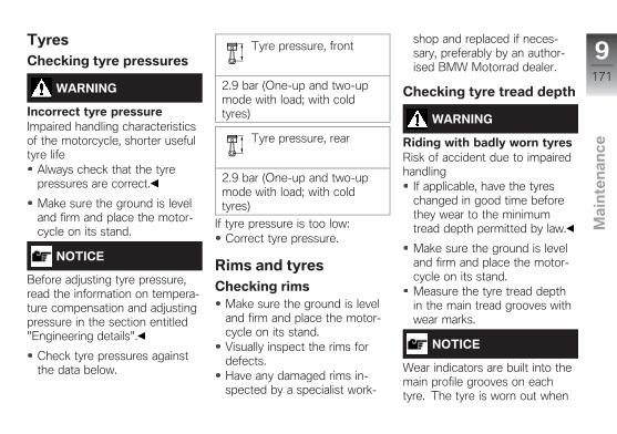
TyresChecking tyre pressures
WARNING
Incorrect tyre pressureImpaired handling characteristicsof the motorcycle, shorter usefultyre life
Always check that the tyrepressures are correct.
Make sure the ground is leveland firm and place the motor-cycle on its stand.
NOTICE
Before adjusting tyre pressure,read the information on tempera-ture compensation and adjustingpressure in the section entitled"Engineering details".
Check tyre pressures againstthe data below.
Tyre pressure, front
2.9 bar (One-up and two-upmode with load; with coldtyres)
Tyre pressure, rear
2.9 bar (One-up and two-upmode with load; with coldtyres)
If tyre pressure is too low:Correct tyre pressure.
Rims and tyresChecking rims
Make sure the ground is leveland firm and place the motor-cycle on its stand.Visually inspect the rims fordefects.Have any damaged rims in-spected by a specialist work-
shop and replaced if neces-sary, preferably by an author-ised BMW Motorrad dealer.
Checking tyre tread depth
WARNING
Riding with badly worn tyresRisk of accident due to impairedhandling
If applicable, have the tyreschanged in good time beforethey wear to the minimumtread depth permitted by law.
Make sure the ground is leveland firm and place the motor-cycle on its stand.Measure the tyre tread depthin the main tread grooves withwear marks.
NOTICE
Wear indicators are built into themain profile grooves on eachtyre. The tyre is worn out when
9171
z Ma
inte
na
nc
e
the tyre tread has worn downto the level of the marks. Thelocations of the marks are indic-ated on the edge of the tyre, e.g.by the letters TI, TWI or by anarrow.
If the tyre tread is worn to min-imum:
Replace tyre or tyres, as applic-able.
WheelsTyre recommendationFor each size of tyre,BMW Motorrad tests andclassifies as roadworthy certainmakes. BMW Motorrad cannotassess the suitability or provideany guarantee of road safety forother tyres.BMW Motorrad recommendsusing only tyres tested byBMW Motorrad.You can obtain detailedinformation from your authorised
BMW Motorrad dealer or byvisiting bmwmotorrad.com.
Effect of wheel size onchassis and suspensioncontrol systemsWheel size is very importantas a parameter for the frameand suspension control systemsABS and DTC. In particular, thediameter and the width of thevehicle's wheels are programmedinto the control unit and are fun-damental to all calculations. Anychange in these influencing vari-ables, caused for example bya switch to wheels other thanthose installed ex-works, canhave serious effects on the per-formance of the control systems.The sensor rings are essentialfor correct wheel speed detec-tion; they too must match themotorcycle's control systems andconsequently cannot be replaced.
If you decide that you would liketo fit non-standard wheels toyour motorcycle, it is very im-portant to consult a specialistworkshop beforehand, preferablyan authorised BMW Motorraddealer. In some cases, the dataprogrammed into the controlunits can be changed to suit thenew wheel sizes.
9172
z Ma
inte
na
nc
e
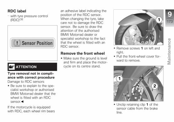
RDC labelwith tyre pressure control(RDC)OE
ATTENTION
Tyre removal not in compli-ance with correct procedureDamage to RDC sensors
Be sure to explain to the spe-cialist workshop or authorisedBMW Motorrad dealer that thewheel is fitted with an RDCsensor.
If the motorcycle is equippedwith RDC, each wheel rim bears
an adhesive label indicating theposition of the RDC sensor.When changing the tyre, takecare not to damage the RDCsensor. Be sure to draw theattention of the authorisedBMW Motorrad dealer orspecialist workshop to the factthat the wheel is fitted with anRDC sensor.
Remove the front wheelMake sure the ground is leveland firm and place the motor-cycle on its centre stand.
Remove screws 1 on left andright.Pull the front-wheel cover for-ward to remove.
Unclip retaining clip 1 of thesensor cable from the brakeline.
9173
z Ma
inte
na
nc
e
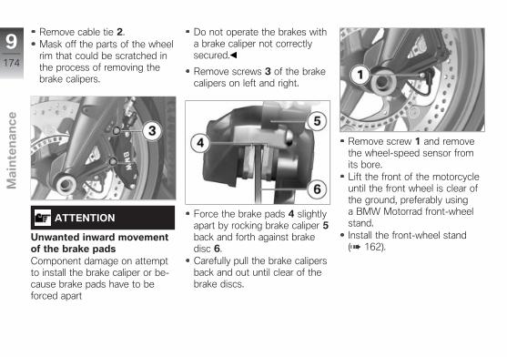
Remove cable tie 2.Mask off the parts of the wheelrim that could be scratched inthe process of removing thebrake calipers.
ATTENTION
Unwanted inward movementof the brake padsComponent damage on attemptto install the brake caliper or be-cause brake pads have to beforced apart
Do not operate the brakes witha brake caliper not correctlysecured.
Remove screws 3 of the brakecalipers on left and right.
Force the brake pads 4 slightlyapart by rocking brake caliper 5back and forth against brakedisc 6.Carefully pull the brake calipersback and out until clear of thebrake discs.
Remove screw 1 and removethe wheel-speed sensor fromits bore.Lift the front of the motorcycleuntil the front wheel is clear ofthe ground, preferably usinga BMW Motorrad front-wheelstand.Install the front-wheel stand( 162).
9174
z Ma
inte
na
nc
e
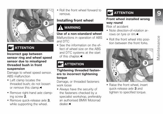
ATTENTION
Incorrect gap betweensensor ring and wheel speedsensor due to misalignedthreaded bush in frontsuspensionDamage to wheel speed sensor.ABS malfunction
Left clamp locates thethreaded bush; do not loosenor remove this clamp.
Remove right-hand axle clamp-ing screw 2.Remove quick-release axle 3,while supporting the wheel.
Roll the front wheel forward toremove.
Installing front wheel
WARNING
Use of a non-standard wheelMalfunctions in operation of ABSand DTC
See the information on the ef-fect of wheel size on the ABSand DTC systems at the startof this chapter.
ATTENTION
Tightening threaded fasten-ers to incorrect tighteningtorqueDamage, or threaded fastenerswork loose
Always have the security ofthe fasteners checked by aspecialist workshop, preferablyan authorised BMW Motorraddealer.
ATTENTION
Front wheel installed wrongway roundRisk of accident
Note direction-of-rotation ar-rows on tyre or rim.
Roll the front wheel into posi-tion between the front forks.
Raise the front wheel, insertquick-release axle 3 andtighten to specified torque.
9175
z Ma
inte
na
nc
e
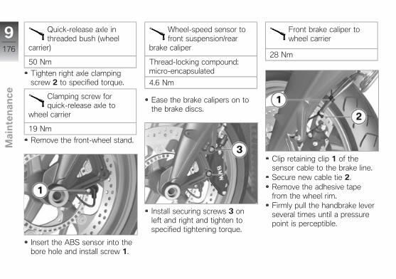
Quick-release axle inthreaded bush (wheel
carrier)
50 Nm
Tighten right axle clampingscrew 2 to specified torque.
Clamping screw forquick-release axle to
wheel carrier
19 Nm
Remove the front-wheel stand.
Insert the ABS sensor into thebore hole and install screw 1.
Wheel-speed sensor tofront suspension/rear
brake caliper
Thread-locking compound:micro-encapsulated
4.6 Nm
Ease the brake calipers on tothe brake discs.
Install securing screws 3 onleft and right and tighten tospecified tightening torque.
Front brake caliper towheel carrier
28 Nm
Clip retaining clip 1 of thesensor cable to the brake line.Secure new cable tie 2.Remove the adhesive tapefrom the wheel rim.Firmly pull the handbrake leverseveral times until a pressurepoint is perceptible.
9176
z Ma
inte
na
nc
e
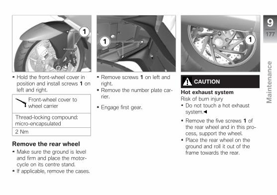
Hold the front-wheel cover inposition and install screws 1 onleft and right.
Front-wheel cover towheel carrier
Thread-locking compound:micro-encapsulated
2 Nm
Remove the rear wheelMake sure the ground is leveland firm and place the motor-cycle on its centre stand.If applicable, remove the cases.
Remove screws 1 on left andright.Remove the number plate car-rier.
Engage first gear.
CAUTION
Hot exhaust systemRisk of burn injury
Do not touch a hot exhaustsystem.
Remove the five screws 1 ofthe rear wheel and in this pro-cess, support the wheel.Place the rear wheel on theground and roll it out of theframe towards the rear.
9177
z Ma
inte
na
nc
e

Install the rear wheel
WARNING
Use of a non-standard wheelMalfunctions in operation of ABSand DTC
See the information on the ef-fect of wheel size on the ABSand DTC systems at the startof this chapter.
ATTENTION
Tightening threaded fasten-ers to incorrect tighteningtorqueDamage, or threaded fastenerswork loose
Always have the security ofthe fasteners checked by aspecialist workshop, preferablyan authorised BMW Motorraddealer.
ATTENTION
Rear wheel installed withtyre's direction of rotationincorrectRisk of accident
Note direction-of-rotation ar-rows on tyre or rim.
Roll the rear wheel to the rear-wheel mounting and position it.
Install the five screws 1 andtighten crosswise to the spe-cified torque.
Rear wheel to wheelflange
Tightening sequence: tightenin diagonally opposite se-quence
60 Nm
Hold number plate carrier 1 inposition and engage retaininglugs 2 in recesses 3 of rearcarrier 4.
9178
z Ma
inte
na
nc
e
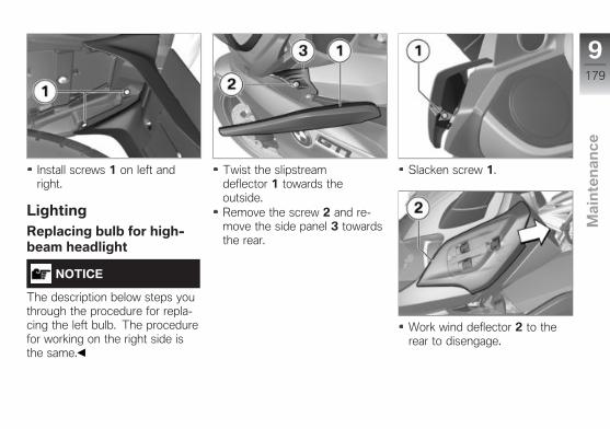
Install screws 1 on left andright.
LightingReplacing bulb for high-beam headlight
NOTICE
The description below steps youthrough the procedure for repla-cing the left bulb. The procedurefor working on the right side isthe same.
Twist the slipstreamdeflector 1 towards theoutside.Remove the screw 2 and re-move the side panel 3 towardsthe rear.
Slacken screw 1.
Work wind deflector 2 to therear to disengage.
9179
z Ma
inte
na
nc
e
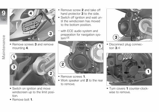
Remove screws 3 and removemounting 4.
Switch on ignition and movewindscreen up to the limit posi-tion.Remove bolt 1.
Remove screw 2 and take offhand protector 3 to the side.Switch off ignition and wait un-til the windscreen has movedto the bottom position.
with ECE audio system andpreparation for navigation sys-tem OE
Remove screws 1.Work speaker unit 2 to the rearto remove.
Disconnect plug connec-tion 3.
Turn covers 1 counter-clock-wise to remove.
9180
z Ma
inte
na
nc
e
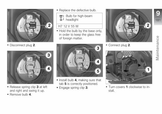
Disconnect plug 2.
Release spring clip 3 at leftand right and swing it up.Remove bulb 4.
Replace the defective bulb.
Bulb for high-beamheadlight
H7 12 V 55 W
Hold the bulb by the base only,in order to keep the glass freeof foreign matter.
Install bulb 4, making sure thattab 5 is correctly positioned.Engage spring clip 3.
Connect plug 2.
Turn covers 1 clockwise to in-stall.
9181
z Ma
inte
na
nc
e
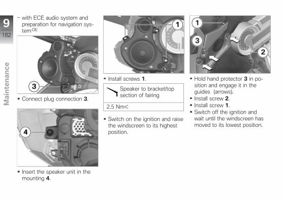
with ECE audio system andpreparation for navigation sys-tem OE
Connect plug connection 3.
Insert the speaker unit in themounting 4.
Install screws 1.
Speaker to bracket/topsection of fairing
2.5 Nm
Switch on the ignition and raisethe windscreen to its highestposition.
Hold hand protector 3 in po-sition and engage it in theguides (arrows).Install screw 2.Install screw 1.Switch off the ignition andwait until the windscreen hasmoved to its lowest position.
9182
z Ma
inte
na
nc
e
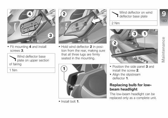
Fit mounting 4 and installscrews 3.
Wind deflector baseplate on upper section
of fairing
1 Nm
Hold wind deflector 2 in posi-tion from the rear, making surethat all three lugs are firmlyseated in the mounting.
Install bolt 1.
Wind deflector on winddeflector base plate
2 Nm
Position the side panel 3 andinstall the screw 2.Align the slipstreamdeflector 1.
Replacing bulb for low-beam headlightThe low-beam headlight can bereplaced only as a complete unit.
9183
z Ma
inte
na
nc
e
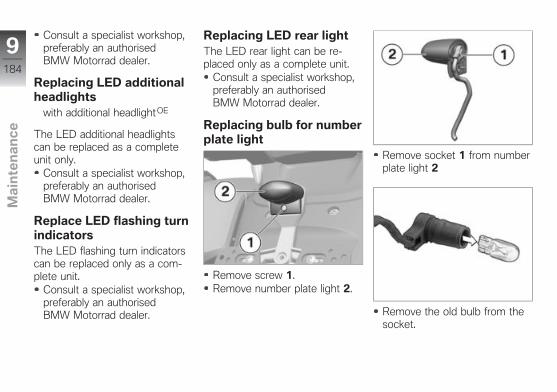
Consult a specialist workshop,preferably an authorisedBMW Motorrad dealer.
Replacing LED additionalheadlights
with additional headlightOE
The LED additional headlightscan be replaced as a completeunit only.
Consult a specialist workshop,preferably an authorisedBMW Motorrad dealer.
Replace LED flashing turnindicatorsThe LED flashing turn indicatorscan be replaced only as a com-plete unit.
Consult a specialist workshop,preferably an authorisedBMW Motorrad dealer.
Replacing LED rear lightThe LED rear light can be re-placed only as a complete unit.
Consult a specialist workshop,preferably an authorisedBMW Motorrad dealer.
Replacing bulb for numberplate light
Remove screw 1.Remove number plate light 2.
Remove socket 1 from numberplate light 2
Remove the old bulb from thesocket.
9184
z Ma
inte
na
nc
e
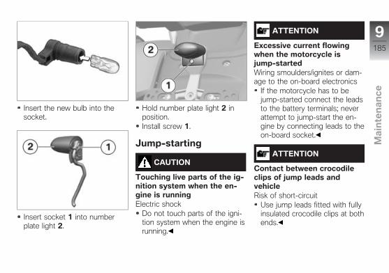
Insert the new bulb into thesocket.
Insert socket 1 into numberplate light 2.
Hold number plate light 2 inposition.Install screw 1.
Jump-starting
CAUTION
Touching live parts of the ig-nition system when the en-gine is runningElectric shock
Do not touch parts of the igni-tion system when the engine isrunning.
ATTENTION
Excessive current flowingwhen the motorcycle isjump-startedWiring smoulders/ignites or dam-age to the on-board electronics
If the motorcycle has to bejump-started connect the leadsto the battery terminals; neverattempt to jump-start the en-gine by connecting leads to theon-board socket.
ATTENTION
Contact between crocodileclips of jump leads andvehicleRisk of short-circuit
Use jump leads fitted with fullyinsulated crocodile clips at bothends.
9185
z Ma
inte
na
nc
e
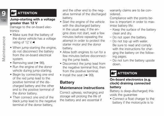
ATTENTION
Jump-starting with a voltagegreater than 12 VDamage to the on-board elec-tronics
Make sure that the battery ofthe donor vehicle has a voltagerating of 12 V.
When jump-starting the engine,do not disconnect the batteryfrom the on-board electricalsystem.Removing seat ( 98).Run the engine of the donorvehicle during jump-starting.Begin by connecting one endof the red jump lead to thepositive terminal of the dis-charged battery and the otherend to the positive terminal ofthe donor battery.Then connect one end of theblack jump lead to the negativeterminal of the donor battery,
and the other end to the neg-ative terminal of the dischargedbattery.Start the engine of the vehiclewith the discharged batteryin the usual way; if the en-gine does not start, wait a fewminutes before repeating theattempt in order to protect thestarter motor and the donorbattery.Allow both engines to run for afew minutes before disconnect-ing the jump leads.Disconnect the jump lead fromthe negative terminal first, thenfrom the positive terminal.Install the seat ( 99).
BatteryMaintenance instructionsCorrect upkeep, recharging andstorage will prolong the life ofthe battery and are essential if
warranty claims are to be con-sidered.Compliance with the points be-low is important in order to max-imise battery life:
Keep the surface of the batteryclean and dry.Do not open the battery.Do not top up with water.Be sure to read and complywith the instructions for char-ging the battery on the follow-ing pages.Do not turn the battery upsidedown.
ATTENTION
On-board electronics (e.g.clock) draining connectedbatteryBattery is deep-discharged; thisvoids the guarantee
Connect a float charger to thebattery if the motorcycle is to
9186
z Ma
inte
na
nc
e
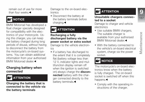
remain out of use for morethan four weeks.
NOTICE
BMW Motorrad has developed afloat charger specially designedfor compatibility with the elec-tronics of your motorcycle. Us-ing this charger, you can keepthe battery charged during longperiods of disuse, without havingto disconnect the battery fromthe motorcycle's on-board sys-tems. You can obtain additionalinformation from your authorisedBMW Motorrad dealer.
Charging battery whenconnected
ATTENTION
Charging the battery that isconnected to the vehicle viathe battery terminals
Damage to the on-board elec-tronics
Disconnect the battery atthe battery terminals beforecharging.
ATTENTION
Recharging a fullydischarged battery via thepower socket or extra socketDamage to the vehicle electron-ics
If a battery has discharged tothe extent that it is completelyflat (battery voltage less than12 V, indicator lights and mul-tifunction display remain offwhen the ignition is switchedon) always charge the discon-nected battery with the char-ger connected directly to thebattery terminals.
ATTENTION
Unsuitable chargers connec-ted to a socketDamage to charger and vehicleelectronics
Use suitable BMW chargers.The suitable charger isavailable from your authorisedBMW Motorrad dealer.
With the battery connected tothe vehicle's on-board electricalsystem, charge via the powersocket.
NOTICE
The motorcycle's on-board elec-tronics know when the batteryis fully charged. The on-boardsocket is switched off when thishappens.
Comply with the operating in-structions of the charger.
9187
z Ma
inte
na
nc
e

NOTICE
If you are unable to charge thebattery through the on-boardsocket, you may be using a char-ger that is not compatible withyour motorcycle's electronics. Inthis case, directly charge the bat-tery at the terminals of the bat-tery that has been disconnectedfrom the vehicle.
Charging battery whendisconnected
Charge the battery using asuitable charger.Comply with the operating in-structions of the charger.Once the battery is fullycharged, disconnect thecharger's terminal clips fromthe battery terminals.
NOTICE
The battery has to be rechargedat regular intervals in the courseof a lengthy period of disuse.See the instructions for caringfor your battery. Always fully re-charge the battery before restor-ing it to use.
Removing batteryRemoving seat ( 98).with anti-theft alarm (DWA) OE
Switch off the anti-theft alarmsystem.
Switch off the ignition.
without intelligent emergencycall OE
ATTENTION
Battery not disconnected inaccordance with correct pro-cedureRisk of short-circuit
Always proceed in compliancewith the specified disconnec-tion sequence.
Disconnect negative batterycable 1.Remove protective cap 2 anddisconnect positive batterycable 3.
9188
z Ma
inte
na
nc
e
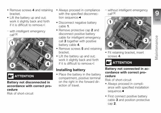
Remove screws 4 and retainingbracket.Lift the battery up and out;work it slightly back and forthif it is difficult to remove.
with intelligent emergencycall OE
ATTENTION
Battery not disconnected inaccordance with correct pro-cedureRisk of short-circuit
Always proceed in compliancewith the specified disconnec-tion sequence.
Disconnect negative batterycable 1.Remove protective cap 2 anddisconnect positive batterycable for intelligent emergencycall 3 together with positivebattery cable 4.Remove screws 5 and retainingbracket.Lift the battery up and out;work it slightly back and forthif it is difficult to remove.
Installing batteryPlace the battery in the batterycompartment, positive terminalon the right in the forward dir-ection of travel.
without intelligent emergencycall OE
Fit retaining bracket, insertscrews 4.
ATTENTION
Battery not connected in ac-cordance with correct pro-cedureRisk of short-circuit
Always proceed in compli-ance with specified installationsequence.
First connect positive batterycable 3 and position protectivecap 2.
9189
z Ma
inte
na
nc
e
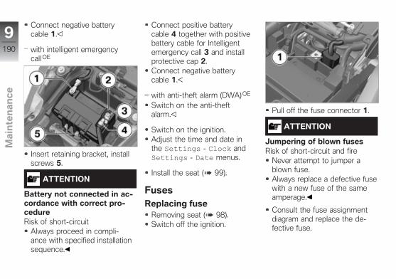
Connect negative batterycable 1.
with intelligent emergencycall OE
Insert retaining bracket, installscrews 5.
ATTENTION
Battery not connected in ac-cordance with correct pro-cedureRisk of short-circuit
Always proceed in compli-ance with specified installationsequence.
Connect positive batterycable 4 together with positivebattery cable for Intelligentemergency call 3 and installprotective cap 2.Connect negative batterycable 1.
with anti-theft alarm (DWA) OE
Switch on the anti-theftalarm.
Switch on the ignition.Adjust the time and date inthe Settings - Clock andSettings - Date menus.
Install the seat ( 99).
FusesReplacing fuse
Removing seat ( 98).Switch off the ignition.
Pull off the fuse connector 1.
ATTENTION
Jumpering of blown fusesRisk of short-circuit and fire
Never attempt to jumper ablown fuse.Always replace a defective fusewith a new fuse of the sameamperage.
Consult the fuse assignmentdiagram and replace the de-fective fuse.
9190
z Ma
inte
na
nc
e

NOTICE
If fuse defects recur frequentlyhave the electric circuits checkedby a specialist workshop,preferably an authorisedBMW Motorrad dealer.
Secure the fuse connector 1.
Install the seat ( 99).
Fuse assignment
1 40 AMain fuse
2 7.5 AAudio system
3 Not usedwith anti-theft alarm(DWA)OE
orwith central locking sys-tem OE
7.5 AAnti-theft alarmCentral locking
Diagnostic connectorDisengaging diagnosticconnector
CAUTION
Incorrect procedurefollowed when loosening thediagnostic connector for theon-board diagnosisMotorcycle experiences malfunc-tions
Only have the diagnostic con-nector loosened by a specialistworkshop or other authorised
persons during your next BMWService appointment.Have the work performed byappropriately trained staff.Refer to the vehicle manufac-turer specifications.
Removing seat ( 98).
Press locks 1.Disengage the diagnostic con-nector 2 from the seat benchbox 3.The interface to the diagnosisand information system canbe connected to diagnosticconnector 2.
9191
z Ma
inte
na
nc
e
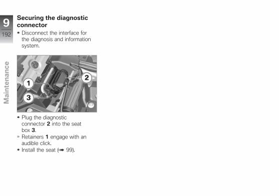
Securing the diagnosticconnector
Disconnect the interface forthe diagnosis and informationsystem.
Plug the diagnosticconnector 2 into the seatbox 3.Retainers 1 engage with anaudible click.Install the seat ( 99).
9192
z Ma
inte
na
nc
e
Accessories
General notes . . . . . . . . . . . . . . . . . . . . . . 194
Power sockets . . . . . . . . . . . . . . . . . . . . . 194
Cases . . . . . . . . . . . . . . . . . . . . . . . . . . . . . . 195
Topcase . . . . . . . . . . . . . . . . . . . . . . . . . . . 197
Navigation device . . . . . . . . . . . . . . . . . . 200
10193
z Ac
ce
sso
rie
s
General notes
CAUTION
Use of other-make productsSafety risk
BMW Motorrad cannot exam-ine or test each product of out-side origin to ensure that it canbe used on or in connectionwith BMW vehicles withoutconstituting a safety hazard.Country-specific official author-isation does not suffice as as-surance. Tests conducted bythese instances cannot makeprovision for all operating con-ditions experienced by BMWvehicles and, consequently,they are not sufficient in somecircumstances.Use only parts and accessor-ies approved by BMW for yourvehicle.
BMW has conducted extens-ive testing of the parts and ac-
cessory products to establishthat they are safe, functional andsuitable. Consequently, BMWaccepts responsibility for theproducts. BMW accepts no li-ability whatsoever for parts andaccessories that it has not ap-proved.All modifications must be in com-pliance with legal requirements.Make sure that the vehicle doesnot infringe the national road-vehicle construction and use reg-ulations applicable in your coun-try.Also bear in mind the informa-tion on the effect of wheel sizeon running-gear control systems( 172).Your BMW Motorrad dealer canoffer expert advice on the choiceof genuine BMW parts, accessor-ies and other products.You can examine all the optionalaccessories from BMW Motorrad
by visiting: "www.bmw-motorrad.com/equipment".
Power socketsNotes on use of power sockets:
Automatic shutdown
If this warning symbol ap-pears it tells you that the
on-board system voltage is low.If necessary, the sockets will betemporarily switched off.
The on-board sockets are alsoswitched off when the engineis being cranked by the starterand if maximum load capabilityas stated in the technical data isexceeded.If more than one socket is used,total current must not exceed themaximum load capability of 10 A.
10194
z Ac
ce
sso
rie
s
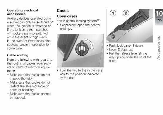
Operating electricalaccessoriesAuxiliary devices operated usinga socket can only be switched onwhen the ignition is switched on.If the ignition is then switchedoff, sockets are also switchedoff in the event of high loads.In the event of lower loads, thesockets remain in operation forsome time.
Cable routingNote the following with regard tothe routing of cables from sock-ets to items of electrical equip-ment:
Make sure that cables do notimpede the rider.Make sure that cables do notrestrict the steering angle orobstruct handling.Make sure that cables cannotbe trapped.
CasesOpen cases
with central locking systemOE
If applicable, open the centrallocking.
Turn the key to the in the caselock to the position indicatedby the dot.
Push lock barrel 1 down.Lever 2 pops up.Pull the release lever all theway up and open the lid of thecase.
10195
z Ac
ce
sso
rie
s
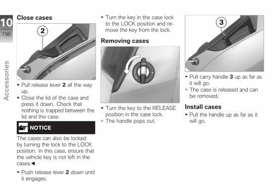
Close cases
Pull release lever 2 all the wayup.Close the lid of the case andpress it down. Check thatnothing is trapped between thelid and the case.
NOTICE
The cases can also be lockedby turning the lock to the LOCKposition. In this case, ensure thatthe vehicle key is not left in thecases.
Push release lever 2 down untilit engages.
Turn the key in the case lockto the LOCK position and re-move the key from the lock.
Removing cases
Turn the key to the RELEASEposition in the case lock.The handle pops out.
Pull carry handle 3 up as far asit will go.The case is released and canbe removed.
Install casesPull the handle up as far as itwill go.
10196
z Ac
ce
sso
rie
s
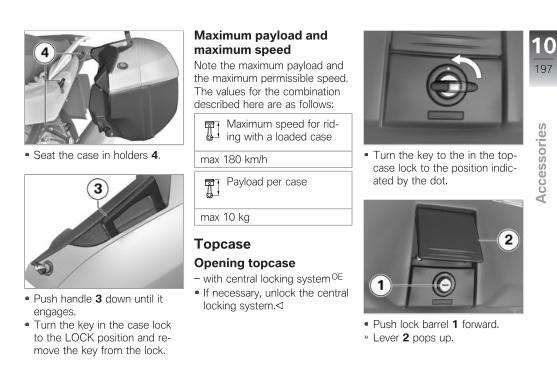
Seat the case in holders 4.
Push handle 3 down until itengages.Turn the key in the case lockto the LOCK position and re-move the key from the lock.
Maximum payload andmaximum speedNote the maximum payload andthe maximum permissible speed.The values for the combinationdescribed here are as follows:
Maximum speed for rid-ing with a loaded case
max 180 km/h
Payload per case
max 10 kg
TopcaseOpening topcase
with central locking systemOE
If necessary, unlock the centrallocking system.
Turn the key to the in the top-case lock to the position indic-ated by the dot.
Push lock barrel 1 forward.Lever 2 pops up.
10197
z Ac
ce
sso
rie
s
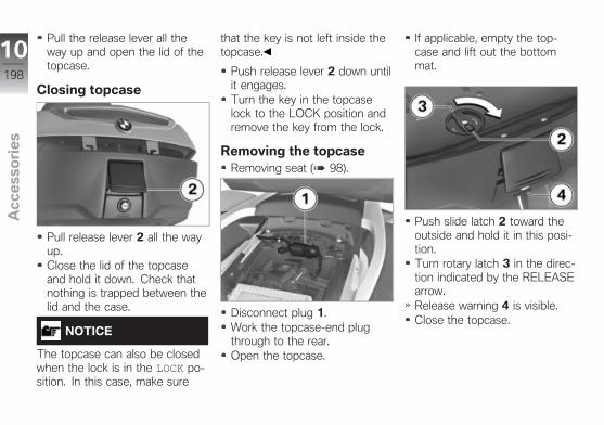
Pull the release lever all theway up and open the lid of thetopcase.
Closing topcase
Pull release lever 2 all the wayup.Close the lid of the topcaseand hold it down. Check thatnothing is trapped between thelid and the case.
NOTICE
The topcase can also be closedwhen the lock is in the LOCK po-sition. In this case, make sure
that the key is not left inside thetopcase.
Push release lever 2 down untilit engages.Turn the key in the topcaselock to the LOCK position andremove the key from the lock.
Removing the topcaseRemoving seat ( 98).
Disconnect plug 1.Work the topcase-end plugthrough to the rear.Open the topcase.
If applicable, empty the top-case and lift out the bottommat.
Push slide latch 2 toward theoutside and hold it in this posi-tion.Turn rotary latch 3 in the direc-tion indicated by the RELEASEarrow.Release warning 4 is visible.Close the topcase.
10198
z Ac
ce
sso
rie
s
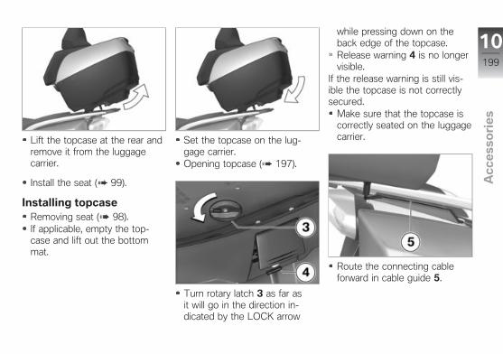
Lift the topcase at the rear andremove it from the luggagecarrier.
Install the seat ( 99).
Installing topcaseRemoving seat ( 98).If applicable, empty the top-case and lift out the bottommat.
Set the topcase on the lug-gage carrier.Opening topcase ( 197).
Turn rotary latch 3 as far asit will go in the direction in-dicated by the LOCK arrow
while pressing down on theback edge of the topcase.Release warning 4 is no longervisible.
If the release warning is still vis-ible the topcase is not correctlysecured.
Make sure that the topcase iscorrectly seated on the luggagecarrier.
Route the connecting cableforward in cable guide 5.
10199
z Ac
ce
sso
rie
s
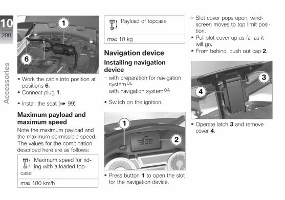
Work the cable into position atpositions 6.Connect plug 1.
Install the seat ( 99).
Maximum payload andmaximum speedNote the maximum payload andthe maximum permissible speed.The values for the combinationdescribed here are as follows:
Maximum speed for rid-ing with a loaded top-
case
max 180 km/h
Payload of topcase
max 10 kg
Navigation deviceInstalling navigationdevice
with preparation for navigationsystemOE
with navigation systemOA
Switch on the ignition.
Press button 1 to open the slotfor the navigation device.
Slot cover pops open, wind-screen moves to top limit posi-tion.Pull slot cover up as far as itwill go.From behind, push out cap 2.
Operate latch 3 and removecover 4.
10200
z Ac
ce
sso
rie
s
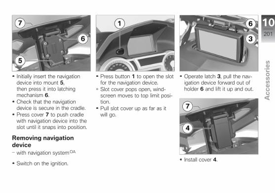
Initially insert the navigationdevice into mount 5,then press it into latchingmechanism 6.Check that the navigationdevice is secure in the cradle.Press cover 7 to push cradlewith navigation device into theslot until it snaps into position.
Removing navigationdevice
with navigation systemOA
Switch on the ignition.
Press button 1 to open the slotfor the navigation device.Slot cover pops open, wind-screen moves to top limit posi-tion.Pull slot cover up as far as itwill go.
Operate latch 3, pull the nav-igation device forward out ofholder 6 and lift it up and out.
Install cover 4.
10201
z Ac
ce
sso
rie
s
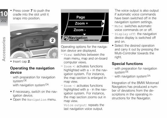
Press cover 7 to push thecradle into the slot until itsnaps into position.
Insert cap 2.
Operating the navigationdevice
with preparation for navigationsystemOE
with navigation systemOA
If necessary, switch on the nav-igation device.Open the Navigation menu.
Operating options for the naviga-tion device are displayed.View: switches between themain menu, map and on-boardcomputer views.Zoom +: activates functionshighlighted with a + in the nav-igation system. For instance,the map section is enlarged inmap view.Zoom –: activates functionshighlighted with a - in the nav-igation system. For instance,the map section zooms out inmap view.Voice output: repeats thelast navigation voice output.
The voice output is also outputif automatic voice commandshave been switched off in thenavigation system settings.Mute: switches automaticvoice commands on or off.Display off: the navigationdevice display is switched offand on.Select the desired operationand carry it out by pressing theMulti-Controller towards theright.
Special functionswith preparation for navigationsystemOE
with navigation systemOA
Integration of the BMW MotorradNavigators has produced a num-ber of deviations from the de-scriptions in the operating in-structions for the Navigator.
10202
z Ac
ce
sso
rie
s
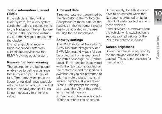
Traffic information channel(TMC)If the vehicle is fitted with anaudio system, the audio systemsends the traffic announcementsto the Navigator. The symbol de-scribed in the operating instruc-tions of the Navigator appears onthe display.It is not possible to receivetraffic announcements fromsubscription services via theBMW Motorrad audio system.
Reserve fuel level warningThe settings for the fuel gaugeenable you to define a distancethat is covered per full tank offuel. The motorcycle sends thefigure for residual range possiblewith the fuel remaining in the fueltank to the Navigator, so it is nolonger necessary to enter thisvalue.
Time and dateTime and date are transmitted bythe Navigator to the motorcycle.Acceptance of these data for thereadings in the instrument clusterhas to be activated in the usersettings for the motorcycle.
Security settingsThe BMW Motorrad Navigator IV,BMW Motorrad Navigator V andBMW Motorrad Navigator VI canbe protected from unauthoriseduse with a four-digit PIN (GarminLock). If this function is activated,while the Navigator is cradled onthe motorcycle and the ignition isswitched on you are prompted toadd the motorcycle to the list ofsecured vehicles. If you answer"Yes" at this prompt the Navig-ator saves the VIN of this vehiclein its internal memory.A maximum of five vehicle identi-fication numbers can be stored.
Subsequently, the PIN does nothave to be entered when theNavigator is switched on by ig-nition ON while cradled in any ofthese vehicles.If the Navigator is removed fromthe vehicle while switched on, asecurity prompt asking for thePIN to be entered is issued.
Screen brightnessScreen brightness is adjusted bythe motorcycle while the unit iscradled. There is no provision formanual input.
10203
z Ac
ce
sso
rie
s

10204
z Ac
ce
sso
rie
s
Care
Care products . . . . . . . . . . . . . . . . . . . . . 206
Washing the vehicle . . . . . . . . . . . . . . . 206
Cleaning easily damaged compon-ents . . . . . . . . . . . . . . . . . . . . . . . . . . . . . . . . 207
Care of paintwork . . . . . . . . . . . . . . . . . . 208
Vehicle preservation . . . . . . . . . . . . . . . 208
Laying up the motorcycle . . . . . . . . . . 208
Restoring motorcycle to use . . . . . . . 209
11205
z Ca
re
Care productsBMW Motorrad recommendsthat you use the cleaningand care products you canobtain from your authorisedBMW Motorrad dealer.The substances in BMWCare Products have been testedin laboratories and in practice;they provide optimised care andprotection for the materials usedin your vehicle.
ATTENTION
Use of unsuitable cleaningand care productsDamage to vehicle parts
Do not use solvents such ascellulose thinners, cold clean-ers, fuel or the like, and donot use cleaning products thatcontain alcohol.
ATTENTION
Use of strongly acidic orstrongly alkaline cleaningagentsDamage to vehicle parts
Dilute in accordance with thedilution ratio stated on thepackaging of the cleaningagent.Do not use strongly acidicor strongly alkaline cleaningagents.
Washing the vehicleBMW Motorrad recommendsthat you use BMW insect re-mover to soften and wash offinsects and stubborn dirt onpainted parts prior to washingthe vehicle.To prevent stains, do not washthe vehicle immediately after ithas been exposed to strong sun-
light and do not wash it in thesun.Make sure that the vehicle iswashed frequently, especiallyduring the winter months.To remove road salt, clean themotorcycle with cold water im-mediately after every trip.
WARNING
Wet brake discs and brakepads after vehicle wash, afterriding through water and inrainy conditionsDiminished braking effect, risk ofaccident
Apply the brakes in good timeto allow the friction and heat todry the brake discs and brakepads.
ATTENTION
Effect of road salt intensifiedby warm waterCorrosion
11206
z Ca
re
Use only cold water to wash offroad salt.
ATTENTION
Damage due to high waterpressure from high pressurecleaners or steam cleanersCorrosion or short circuit, dam-age to labels, seals, hydraulicbrake system, electrical systemand the motorcycle seat
Exercise restraint when usinga steam jet or high pressurecleaning equipment.
Cleaning easilydamaged componentsPlastics
ATTENTION
Use of unsuitable cleaningagentsDamage to plastic surfaces
Do not use cleaning agentsthat contain alcohol, solvents orabrasives.Do not use insect-removerpads or cleaning pads withhard, scouring surfaces.
Body panelsClean trim panel componentswith water and BMW Motorradsolvent cleaner.
Plastic windscreens andheadlight lensesRemove dirt and insects witha soft sponge and generousamounts of water.
NOTICE
Soften stubborn dirt and insectsby covering the affected areaswith a wet cloth.
ChromeCarefully clean chrome sectionswith a generous amount of waterand motorcycle cleaner from thecare series BMW Motorrad CareProducts. This applies especiallywhere road salt has been in use.For an additional treatment, useBMW Motorrad metal polish.
RadiatorClean the radiator regularly toprevent overheating of the en-gine due to inadequate cooling.For example, use a garden hosewith low water pressure.
ATTENTION
Bending of radiator finsDamage to radiator fins
Take care not to bend the radi-ator fins when cleaning.
11207
z Ca
re
RubberTreat rubber components withwater or BMW rubber-careproducts.
ATTENTION
Application of silicone spraysto rubber sealsDamage to the rubber seals
Do not use silicone spraysor care products that containsilicon.
Care of paintworkThe long-term effects of mater-ials that are damaging to paintcan be prevented by regularvehicle washes, particularly ifyour vehicle is ridden in areassusceptible to high levels of airpollution or natural contamination,for example tree resin or pollen.Particularly aggressive materials,however, should be removedimmediately, otherwise changes
to or discolouration of the paintcan result. These include, forexample, spilled fuel, oil, grease,brake fluid or bird excrement.For this, we recommendBMW Motorrad solvent cleanerfollowed by BMW Motorrad glosspolish for preservation.Contamination of the paintsurface can be seen particularlyclearly after a vehicle wash.These areas should be cleanedimmediately using benzine orspirit, applied with a clean clothor cotton pad. BMW Motorradrecommends that tar spotsbe removed using BMW tarremover. The paint should thenbe preserved in these areas.
Vehicle preservationIf water no longer rolls off thepaint, the paint must be pre-served.For paint preservation,BMW Motorrad recommends
the use of BMW Motorrad glosspolish or agents containingcarnauba wax or synthetic wax.
Laying up themotorcycle
Clean the motorcycle.
Fill the motorcycle's fuel tankwith fuel.
Remove the battery ( 188).Spray the brake and clutchlever pivots and the side-standand centre-stand pivot mountswith a suitable lubricant.
Coat bright metal and chrome-plated parts with an acid-freegrease (e.g. Vaseline).
Park the motorcycle in a dryroom so that no load appliesto either wheel (preferably us-ing the front-wheel and rear-wheel stand available fromBMW Motorrad).
11208
z Ca
re

Restoring motorcycleto use
Remove the protective waxcoating.Clean the motorcycle.
Install the battery ( 189).Comply with checklist ( 136).
11209
z Ca
re

11210
z Ca
re
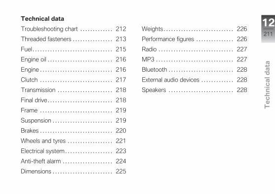
Technical data
Troubleshooting chart . . . . . . . . . . . . . 212
Threaded fasteners . . . . . . . . . . . . . . . . 213
Fuel . . . . . . . . . . . . . . . . . . . . . . . . . . . . . . . . 215
Engine oil . . . . . . . . . . . . . . . . . . . . . . . . . . 216
Engine . . . . . . . . . . . . . . . . . . . . . . . . . . . . . 216
Clutch . . . . . . . . . . . . . . . . . . . . . . . . . . . . . 217
Transmission . . . . . . . . . . . . . . . . . . . . . . 218
Final drive . . . . . . . . . . . . . . . . . . . . . . . . . . 218
Frame . . . . . . . . . . . . . . . . . . . . . . . . . . . . . 219
Suspension . . . . . . . . . . . . . . . . . . . . . . . . 219
Brakes . . . . . . . . . . . . . . . . . . . . . . . . . . . . . 220
Wheels and tyres . . . . . . . . . . . . . . . . . . 221
Electrical system . . . . . . . . . . . . . . . . . . . 223
Anti-theft alarm . . . . . . . . . . . . . . . . . . . . 224
Dimensions . . . . . . . . . . . . . . . . . . . . . . . . 225
Weights . . . . . . . . . . . . . . . . . . . . . . . . . . . . 226
Performance figures . . . . . . . . . . . . . . . 226
Radio . . . . . . . . . . . . . . . . . . . . . . . . . . . . . . 227
MP3 . . . . . . . . . . . . . . . . . . . . . . . . . . . . . . . 227
Bluetooth . . . . . . . . . . . . . . . . . . . . . . . . . . 228
External audio devices . . . . . . . . . . . . . 228
Speakers . . . . . . . . . . . . . . . . . . . . . . . . . . 228
12211
z Te
ch
nic
al d
ata
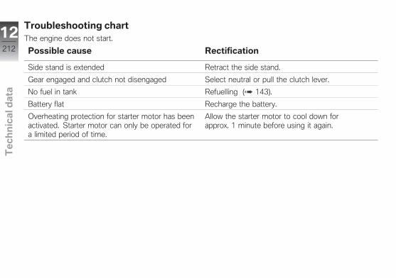
Troubleshooting chartThe engine does not start.
Possible cause Rectification
Side stand is extended Retract the side stand.
Gear engaged and clutch not disengaged Select neutral or pull the clutch lever.
No fuel in tank Refuelling ( 143).
Battery flat Recharge the battery.
Overheating protection for starter motor has beenactivated. Starter motor can only be operated fora limited period of time.
Allow the starter motor to cool down forapprox. 1 minute before using it again.
12212
z Te
ch
nic
al d
ata
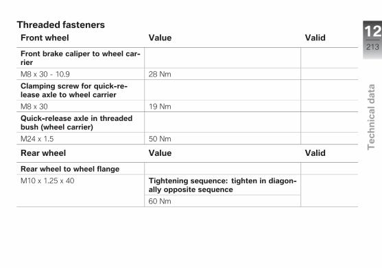
Threaded fastenersFront wheel Value Valid
Front brake caliper to wheel car-rier
M8 x 30 - 10.9 28 Nm
Clamping screw for quick-re-lease axle to wheel carrier
M8 x 30 19 Nm
Quick-release axle in threadedbush (wheel carrier)
M24 x 1.5 50 Nm
Rear wheel Value Valid
Rear wheel to wheel flange
M10 x 1.25 x 40 Tightening sequence: tighten in diagon-ally opposite sequence
60 Nm
12213
z Te
ch
nic
al d
ata
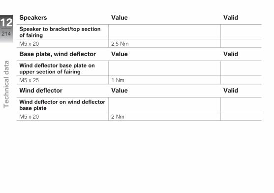
Speakers Value Valid
Speaker to bracket/top sectionof fairing
M5 x 20 2.5 Nm
Base plate, wind deflector Value Valid
Wind deflector base plate onupper section of fairing
M5 x 25 1 Nm
Wind deflector Value Valid
Wind deflector on wind deflectorbase plate
M5 x 20 2 Nm
12214
z Te
ch
nic
al d
ata
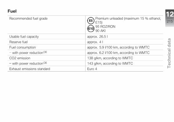
Fuel
Recommended fuel grade Premium unleaded (maximum 15 % ethanol,E15)95 ROZ/RON90 AKI
Usable fuel capacity approx. 26.5 l
Reserve fuel approx. 4 l
Fuel consumption approx. 5.9 l/100 km, according to WMTC
with power reductionOE approx. 6.2 l/100 km, according to WMTC
CO2 emission 138 g/km, according to WMTC
with power reductionOE 143 g/km, according to WMTC
Exhaust emissions standard Euro 4
12215
z Te
ch
nic
al d
ata
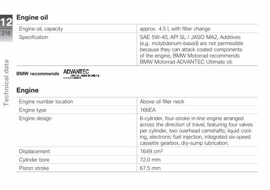
Engine oil
Engine oil, capacity approx. 4.5 l, with filter change
Specification SAE 5W-40, API SL / JASO MA2, Additives(e.g. molybdenum-based) are not permissiblebecause they can attack coated componentsof the engine, BMW Motorrad recommendsBMW Motorrad ADVANTEC Ultimate oil.
BMW recommends
Engine
Engine number location Above oil filler neck
Engine type 166EA
Engine design 6-cylinder, four-stroke in-line engine arrangedacross the direction of travel, featuring four valvesper cylinder, two overhead camshafts; liquid cool-ing, electronic fuel injection, integrated six-speedcassette gearbox, dry-sump lubrication.
Displacement 1649 cm3
Cylinder bore 72.0 mm
Piston stroke 67.5 mm
12216
z Te
ch
nic
al d
ata

Compression ratio 12.2:1
Nominal capacity 118 kW, at engine speed: 7750 min-1
with power reductionOE 79 kW, at engine speed: 7750 min-1
Torque 175 Nm, at engine speed: 5250 min-1
with power reductionOE 155 Nm, at engine speed: 4750 min-1
Maximum engine speed max 8500 min-1
Idle speed 900±50 min-1, Engine at regular operating temper-ature
Clutch
Clutch type Multi-disc oil bath
12217
z Te
ch
nic
al d
ata
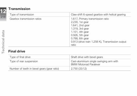
Transmission
Type of transmission Claw-shift 6-speed gearbox with helical gearing
Gearbox transmission ratios 1.617, Primary transmission ratio2.230, 1st gear1.641, 2nd gear1.319, 3rd gear1.101, 4th gear0.926, 5th gear0.788, 6th gear0.913 (drive train 1.258 K), Transmission outputratio
Final drive
Type of final drive Shaft drive with bevel gears
Type of rear suspension Cast-aluminium single swinging arm withBMW Motorrad Paralever
Number of teeth in bevel gears (gear ratio) 2.750 (33:12)
12218
z Te
ch
nic
al d
ata
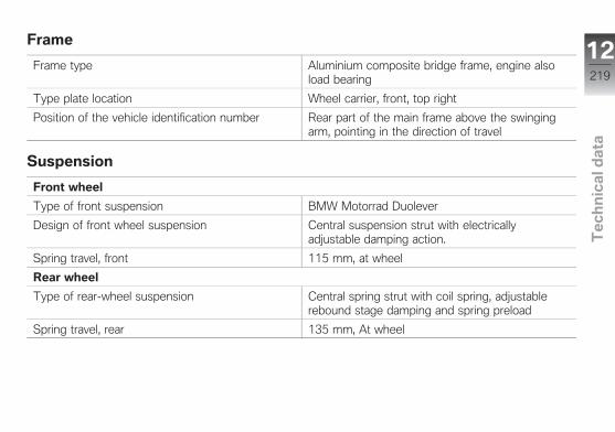
Frame
Frame type Aluminium composite bridge frame, engine alsoload bearing
Type plate location Wheel carrier, front, top right
Position of the vehicle identification number Rear part of the main frame above the swingingarm, pointing in the direction of travel
Suspension
Front wheel
Type of front suspension BMW Motorrad Duolever
Design of front wheel suspension Central suspension strut with electricallyadjustable damping action.
Spring travel, front 115 mm, at wheel
Rear wheel
Type of rear-wheel suspension Central spring strut with coil spring, adjustablerebound stage damping and spring preload
Spring travel, rear 135 mm, At wheel
12219
z Te
ch
nic
al d
ata
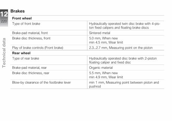
Brakes
Front wheel
Type of front brake Hydraulically operated twin disc brake with 4-pis-ton fixed calipers and floating brake discs
Brake-pad material, front Sintered metal
Brake disc thickness, front 5.0 mm, When newmin 4.5 mm, Wear limit
Play of brake controls (Front brake) 2.3...2.7 mm, Measuring point on the piston
Rear wheel
Type of rear brake Hydraulically operated disc brake with 2-pistonfloating caliper and fixed disc
Brake-pad material, rear Organic material
Brake disc thickness, rear 5.5 mm, When newmin 4.9 mm, Wear limit
Blow-by clearance of the footbrake lever min 1 mm, Measuring point between piston andpushrod
12220
z Te
ch
nic
al d
ata
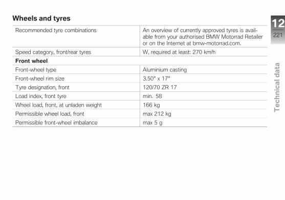
Wheels and tyres
Recommended tyre combinations An overview of currently approved tyres is avail-able from your authorised BMW Motorrad Retaileror on the Internet at bmw-motorrad.com.
Speed category, front/rear tyres W, required at least: 270 km/h
Front wheel
Front-wheel type Aluminium casting
Front-wheel rim size 3.50" x 17"
Tyre designation, front 120/70 ZR 17
Load index, front tyre min. 58
Wheel load, front, at unladen weight 166 kg
Permissible wheel load, front max 212 kg
Permissible front-wheel imbalance max 5 g
12221
z Te
ch
nic
al d
ata

Rear wheel
Rear-wheel type Aluminium casting
Rear wheel rim size 6.00" x 17"
Tyre designation, rear 190/55 ZR 17
Load index, rear tyre min. 75
Wheel load, rear, at unladen weight 184 kg
Permissible wheel load, rear max 368 kg
Permissible rear-wheel imbalance max 45 g
Tyre pressure
Tyre pressure, front 2.9 bar, One-up and two-up mode with load; withcold tyres
Tyre pressure, rear 2.9 bar, One-up and two-up mode with load; withcold tyres
12222
z Te
ch
nic
al d
ata

Electrical system
Electrical rating of on-board sockets max 10 A, All sockets in total
Battery
Battery type AGM
Battery rated voltage 12 V
Battery rated capacity 16 Ah
Spark plugs
Spark plugs, manufacturer and designation NGK LMAR8AI-8
Light source
Bulb for high-beam headlight H7 12 V 55 W
Bulbs for the low-beam headlight Xenon D1S 12 V 35 W
Bulb for parking light LED ring light
Bulb for tail light/brake light LED
Bulbs for turn indicators LED
Bulbs for flashing turn indicators, rear LED
Light source for the number plate light W5W / 12 V / 5 W
12223
z Te
ch
nic
al d
ata
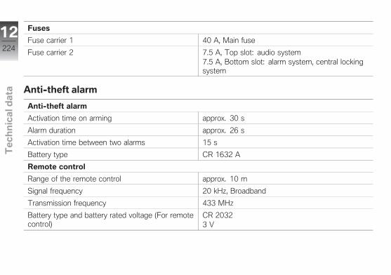
Fuses
Fuse carrier 1 40 A, Main fuse
Fuse carrier 2 7.5 A, Top slot: audio system7.5 A, Bottom slot: alarm system, central lockingsystem
Anti-theft alarm
Anti-theft alarm
Activation time on arming approx. 30 s
Alarm duration approx. 26 s
Activation time between two alarms 15 s
Battery type CR 1632 A
Remote control
Range of the remote control approx. 10 m
Signal frequency 20 kHz, Broadband
Transmission frequency 433 MHz
Battery type and battery rated voltage (For remotecontrol)
CR 20323 V
12224
z Te
ch
nic
al d
ata
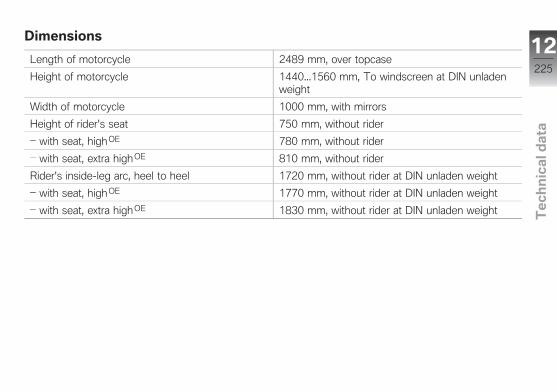
Dimensions
Length of motorcycle 2489 mm, over topcase
Height of motorcycle 1440...1560 mm, To windscreen at DIN unladenweight
Width of motorcycle 1000 mm, with mirrors
Height of rider's seat 750 mm, without rider
with seat, high OE 780 mm, without rider
with seat, extra high OE 810 mm, without rider
Rider's inside-leg arc, heel to heel 1720 mm, without rider at DIN unladen weight
with seat, high OE 1770 mm, without rider at DIN unladen weight
with seat, extra high OE 1830 mm, without rider at DIN unladen weight
12225
z Te
ch
nic
al d
ata
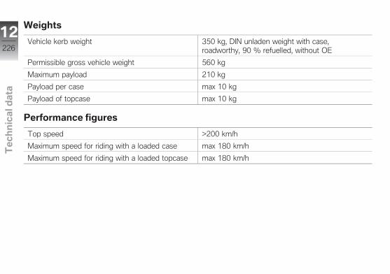
Weights
Vehicle kerb weight 350 kg, DIN unladen weight with case,roadworthy, 90 % refuelled, without OE
Permissible gross vehicle weight 560 kg
Maximum payload 210 kg
Payload per case max 10 kg
Payload of topcase max 10 kg
Performance figures
Top speed >200 km/h
Maximum speed for riding with a loaded case max 180 km/h
Maximum speed for riding with a loaded topcase max 180 km/h
12226
z Te
ch
nic
al d
ata
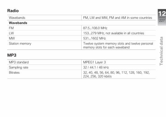
Radio
Wavebands FM, LW and MW, FM and AM in some countries
Wavebands
FM 87.5...108.0 MHz
LW 153...279 MHz, not available in all countries
MW 531...1602 MHz
Station memory Twelve system memory slots and twelve personalmemory slots for each waveband
MP3
MP3 standard MPEG1 Layer 3
Sampling rate 32 / 44.1 / 48 kHz
Bitrates 32, 40, 48, 56, 64, 80, 96, 112, 128, 160, 192,224, 256, 320 kbit/s
12227
z Te
ch
nic
al d
ata
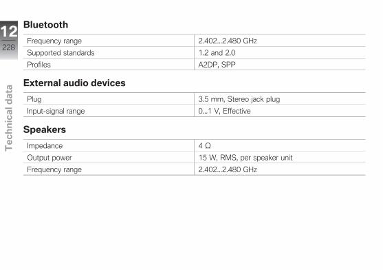
Bluetooth
Frequency range 2.402...2.480 GHz
Supported standards 1.2 and 2.0
Profiles A2DP, SPP
External audio devices
Plug 3.5 mm, Stereo jack plug
Input-signal range 0...1 V, Effective
Speakers
Impedance 4 Ω
Output power 15 W, RMS, per speaker unit
Frequency range 2.402...2.480 GHz
12228
z Te
ch
nic
al d
ata
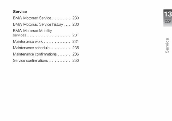
Service
BMW Motorrad Service . . . . . . . . . . . . 230
BMW Motorrad Service history . . . . 230
BMW Motorrad Mobilityservices . . . . . . . . . . . . . . . . . . . . . . . . . . . . 231
Maintenance work . . . . . . . . . . . . . . . . . 231
Maintenance schedule . . . . . . . . . . . . . 235
Maintenance confirmations . . . . . . . . 236
Service confirmations . . . . . . . . . . . . . . 250
13229
z Se
rvic
e
BMW Motorrad ServiceBMW Motorrad has an extensivenetwork of dealerships in placeto look after you and your mo-torcycle in more than 100 coun-tries. Authorised BMW Motorraddealerships have the technicalinformation and the technicalknow-how to carry out reliablyall maintenance and repair workon your BMW.You can locate your nearest au-thorised BMW Motorrad dealer-ship by visiting our website:bmw-motorrad.com
WARNING
Maintenance and repair worknot in compliance with cor-rect procedureRisk of accident due to con-sequential damage
BMW Motorrad recommendshaving work of this nature car-ried out on the vehicle by a
specialist workshop, preferablyan authorised BMW Motorraddealer.
In order to help ensure that yourBMW is always in optimumcondition, BMW Motorradrecommends compliance withthe maintenance intervalsspecified for your motorcycle.Have all maintenance and re-pair work that is carried out con-firmed in the "Service" chapter inthis manual. For generous treat-ment of claims submitted afterthe warranty period has expired,evidence of regular maintenanceis essential.
Your authorised BMW Motorraddealer can provide information onBMW services and the work un-dertaken as part of each service.
BMW Motorrad ServicehistoryEntriesMaintenance work that has beencarried out is entered in the proofof maintenance. The entriesare like a Service Booklet andprovide proof of regular mainten-ance.When an entry is made in theelectronic service booklet of thevehicle, service-relevant data issaved in the central IT systemsof BMW AG, Munich, Germany.If there is a change in vehicleowner, the data saved in theelectronic service booklet canalso be viewed by the newvehicle owner. A BMW Motorradretailer or a specialist workshopcan also view data that is storedin the electronic service booklet.
13230
z Se
rvic
e
ObjectionThe vehicle owner can objectto entries being made by theBMW Motorrad retailer or a spe-cialist workshop in the electronicservice booklet along with thecorresponding storage of data inthe vehicle and transfer of datato the vehicle manufacturer forthe period of time that they arethe vehicle owner. In this in-stance, no entry is made in theelectronic service booklet of thevehicle.
BMW Motorrad MobilityservicesAs owner of a new BMWmotorcycle, in circumstancesin which assistance is requiredyou can benefit from theprotection afforded by the variousBMW Motorrad mobility services(e.g. Mobile Service, breakdownservice, vehicle recovery service).
Your authorised BMW Motorraddealer will be happy provide in-formation about the mobility ser-vices available to you.
Maintenance workBMW Pre-delivery CheckYour authorised BMW Motorraddealer conducts the BMW pre-delivery check before handingover the vehicle to you.
BMW Running-in CheckThe BMW running-in check hasto be performed when the mo-torcycle has covered between500 km and 1200 km
BMW ServiceThe BMW Service is carried outonce a year. The scope of theservice depends on the age ofthe vehicle and the mileage rid-den. Your BMW Motorrad Re-tailer will confirm the service thathas been carried out for you and
will enter the deadline for thenext service.For riders with a high mileageit may be necessary to havea service before the specifieddeadline. In this case, a corres-ponding maximum mileage isentered in the service confirm-ation. If this mileage is reachedbefore the next service deadline,the service must be brought for-ward.
The service display in the multi-function display reminds you ap-prox. one month or 1000 km inadvance of the imminent servicedeadline before the entered val-ues are reached.
To find out more about service,go to:bmw-motorrad.com/service
13231
z Se
rvic
e
The scope of maintenance workrequired for your vehicle can befound in the following mainten-ance schedule:
13232
z Se
rvic
e

13233
z Se
rvic
e
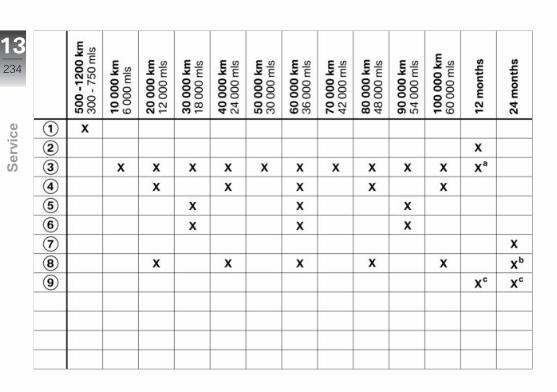
13234
z Se
rvic
e

Maintenance schedule1 BMW running-in check
(including oil change)2 BMW Service standard
scope3 Engine-oil change, with
filter4 Replace air filter element5 Check valve clearance6 Replace all spark plugs7 Check the bearing for de-
flection on the rear wheelswinging arm
8 Oil change in bevel gearsrear
9 Change brake fluid, entiresystem
a annually or every10000 km (whichevercomes first)
b every 2 years or every20000 km (whichevercomes first)
c for the first time after oneyear, then every two years
13235
z Se
rvic
e
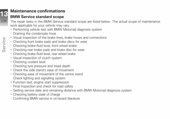
Maintenance confirmationsBMW Service standard scopeThe repair tasks in the BMW Service standard scope are listed below. The actual scope of maintenancework applicable for your vehicle may vary.
Performing vehicle test with BMW Motorrad diagnosis systemDraining the condensate hoseVisual inspection of the brake lines, brake hoses and connectionsChecking front brake pads and brake discs for wearChecking brake-fluid level, front wheel brakeChecking rear brake pads and brake disc for wearChecking brake-fluid level, rear wheel brakeVisual inspection of clutch systemChecking coolant levelChecking tyre pressure and tread depthCheck the side stand's ease of movementChecking ease of movement of the centre standCheck lighting and signalling systemFunction test, engine start suppressionFinal inspection and check for road safetySetting service date and remaining distance with BMW Motorrad diagnosis systemChecking battery state of chargeConfirming BMW service in on-board literature
13236
z Se
rvic
e
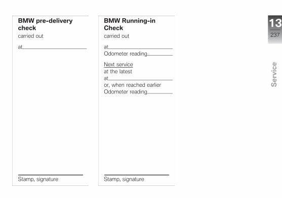
BMW pre-deliverycheckcarried out
at
Stamp, signature
BMW Running-inCheckcarried out
atOdometer reading
Next serviceat the latestator, when reached earlierOdometer reading
Stamp, signature
13237
z Se
rvic
e

BMW Servicecarried out
atOdometer reading
Next serviceat the latestator, when reached earlierOdometer reading
Stamp, signature
Work performedYes No
BMW Service
Oil change, engine, with filterRenewing air cleaner insertChecking valve clearanceRenewing all spark plugsOil change in rear bevel gearsChange brake fluid in entire system
Notes
13238
z Se
rvic
e

BMW Servicecarried out
atOdometer reading
Next serviceat the latestator, when reached earlierOdometer reading
Stamp, signature
Work performedYes No
BMW Service
Oil change, engine, with filterRenewing air cleaner insertChecking valve clearanceRenewing all spark plugsOil change in rear bevel gearsChange brake fluid in entire system
Notes
13239
z Se
rvic
e

BMW Servicecarried out
atOdometer reading
Next serviceat the latestator, when reached earlierOdometer reading
Stamp, signature
Work performedYes No
BMW Service
Oil change, engine, with filterRenewing air cleaner insertChecking valve clearanceRenewing all spark plugsOil change in rear bevel gearsChange brake fluid in entire system
Notes
13240
z Se
rvic
e

BMW Servicecarried out
atOdometer reading
Next serviceat the latestator, when reached earlierOdometer reading
Stamp, signature
Work performedYes No
BMW Service
Oil change, engine, with filterRenewing air cleaner insertChecking valve clearanceRenewing all spark plugsOil change in rear bevel gearsChange brake fluid in entire system
Notes
13241
z Se
rvic
e

BMW Servicecarried out
atOdometer reading
Next serviceat the latestator, when reached earlierOdometer reading
Stamp, signature
Work performedYes No
BMW Service
Oil change, engine, with filterRenewing air cleaner insertChecking valve clearanceRenewing all spark plugsOil change in rear bevel gearsChange brake fluid in entire system
Notes
13242
z Se
rvic
e

BMW Servicecarried out
atOdometer reading
Next serviceat the latestator, when reached earlierOdometer reading
Stamp, signature
Work performedYes No
BMW Service
Oil change, engine, with filterRenewing air cleaner insertChecking valve clearanceRenewing all spark plugsOil change in rear bevel gearsChange brake fluid in entire system
Notes
13243
z Se
rvic
e
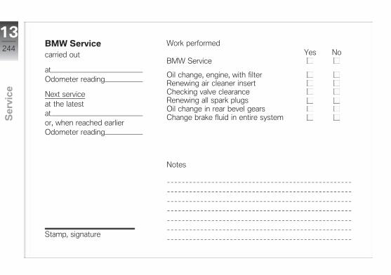
BMW Servicecarried out
atOdometer reading
Next serviceat the latestator, when reached earlierOdometer reading
Stamp, signature
Work performedYes No
BMW Service
Oil change, engine, with filterRenewing air cleaner insertChecking valve clearanceRenewing all spark plugsOil change in rear bevel gearsChange brake fluid in entire system
Notes
13244
z Se
rvic
e
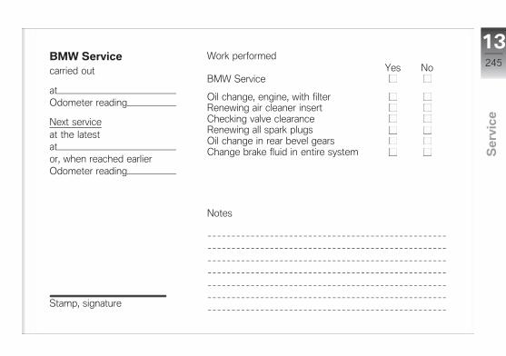
BMW Servicecarried out
atOdometer reading
Next serviceat the latestator, when reached earlierOdometer reading
Stamp, signature
Work performedYes No
BMW Service
Oil change, engine, with filterRenewing air cleaner insertChecking valve clearanceRenewing all spark plugsOil change in rear bevel gearsChange brake fluid in entire system
Notes
13245
z Se
rvic
e

BMW Servicecarried out
atOdometer reading
Next serviceat the latestator, when reached earlierOdometer reading
Stamp, signature
Work performedYes No
BMW Service
Oil change, engine, with filterRenewing air cleaner insertChecking valve clearanceRenewing all spark plugsOil change in rear bevel gearsChange brake fluid in entire system
Notes
13246
z Se
rvic
e

BMW Servicecarried out
atOdometer reading
Next serviceat the latestator, when reached earlierOdometer reading
Stamp, signature
Work performedYes No
BMW Service
Oil change, engine, with filterRenewing air cleaner insertChecking valve clearanceRenewing all spark plugsOil change in rear bevel gearsChange brake fluid in entire system
Notes
13247
z Se
rvic
e
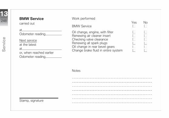
BMW Servicecarried out
atOdometer reading
Next serviceat the latestator, when reached earlierOdometer reading
Stamp, signature
Work performedYes No
BMW Service
Oil change, engine, with filterRenewing air cleaner insertChecking valve clearanceRenewing all spark plugsOil change in rear bevel gearsChange brake fluid in entire system
Notes
13248
z Se
rvic
e

BMW Servicecarried out
atOdometer reading
Next serviceat the latestator, when reached earlierOdometer reading
Stamp, signature
Work performedYes No
BMW Service
Oil change, engine, with filterRenewing air cleaner insertChecking valve clearanceRenewing all spark plugsOil change in rear bevel gearsChange brake fluid in entire system
Notes
13249
z Se
rvic
e
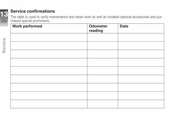
Service confirmationsThe table is used to verify maintenance and repair work as well as installed optional accessories and pur-chased special promotions.
Work performed Odometerreading
Date
13250
z Se
rvic
e
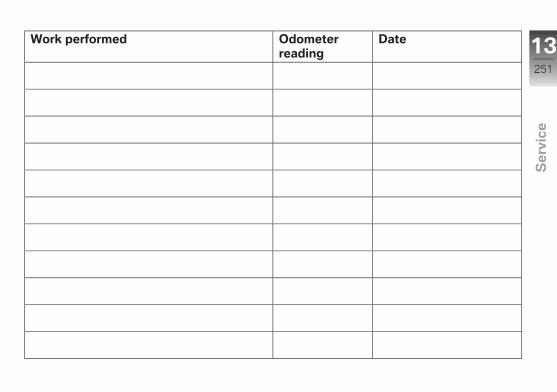
Work performed Odometerreading
Date 13251
z Se
rvic
e

13252
z Se
rvic
e
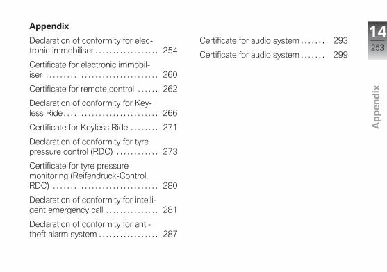
Appendix
Declaration of conformity for elec-tronic immobiliser . . . . . . . . . . . . . . . . . . 254
Certificate for electronic immobil-iser . . . . . . . . . . . . . . . . . . . . . . . . . . . . . . . . 260
Certificate for remote control . . . . . . 262
Declaration of conformity for Key-less Ride . . . . . . . . . . . . . . . . . . . . . . . . . . . 266
Certificate for Keyless Ride . . . . . . . . 271
Declaration of conformity for tyrepressure control (RDC) . . . . . . . . . . . . 273
Certificate for tyre pressuremonitoring (Reifendruck-Control,RDC) . . . . . . . . . . . . . . . . . . . . . . . . . . . . . . 280
Declaration of conformity for intelli-gent emergency call . . . . . . . . . . . . . . . 281
Declaration of conformity for anti-theft alarm system . . . . . . . . . . . . . . . . . 287
Certificate for audio system . . . . . . . . 293
Certificate for audio system . . . . . . . . 299
14253
z Ap
pe
nd
ix
Declaration of Conformity
Radio equipment electronic immobiliser (EWS) Simplified EU Declaration of Conformity acc. Radio Equipment Directive 2014/53/EU after 12.06.2016 and during transition period
Technical information Frequency Band: 134 kHz (Transponder: TMS37145 / TypeDST80, TMS3705 Transponder Base Station IC) Output Power : 50 dBµV/m
Manufacturer and Address Manufacturer: BECOM Electronics GmbH Adress: Technikerstraße 1, A-7442 Hochstraß
Austria Hiermit erklärt BECOM Electronics GmbH, dass der Funkanlagentyp EWS4 der Richtlinie 2014/53/EU entspricht. Der vollständige Text der EU-Konformitätserklärung ist unter der folgenden Internetadresse verfügbar: http://www.becom.at/de/download/
Belgium Le soussigné, BECOM Electronics GmbH, déclare que l'équipement radioélectrique du type EWS4 est conforme à la directive 2014/53/UE. Le texte complet de la déclaration UE de conformité est disponible à l'adresse internet suivante:http://www.becom.at/de/download/
Bulgaria С настоящото BECOM Electronics GmbH декларира, че този тип радиосъоръжение EWS4 е в съответствие с Директива 2014/53/ЕС. Цялостният текст на ЕС декларацията за съответствие може да се намери на следния интернет адрес: http://www.becom.at/de/download/
Cyprus Με την παρούσα ο/η BECOM Electronics GmbH, δηλώνει ότι ο ραδιοεξοπλισμός EWS4 πληροί την οδηγία 2014/53/ΕΕ. Το πλήρες κείμενο της δήλωσης συμμόρφωσης ΕΕ διατίθεται στην ακόλουθη ιστοσελίδα στο διαδίκτυο: http://www.becom.at/de/download/
Czech Republic Tímto BECOM Electronics GmbH prohlašuje, že typ rádiového zařízení EWS4 je v souladu se směrnicí 2014/53/EU. Úplné znění EU prohlášení o shodě je k dispozici na této internetové adrese: http://www.becom.at/de/download/
Germany Hiermit erklärt BECOM Electronics GmbH, dass der Funkanlagentyp EWS4 der Richtlinie 2014/53/EU entspricht. Der vollständige Text der EU-Konformitätserklärung ist unter der folgenden Internetadresse verfügbar: http://www.becom.at/de/download/
Denmark Hermed erklærer BECOM Electronics GmbH, at radioudstyrstypen EWS4 er i overensstemmelse med direktiv 2014/53/EU. EU-overensstemmelseserklæringens fulde tekst kan findes på følgende internetadresse: http://www.becom.at/de/download/
Estonia Käesolevaga deklareerib BECOM Electronics GmbH, et käesolev raadioseadme tüüp EWS4 vastab direktiivi 2014/53/EL nõuetele. ELi vastavusdeklaratsiooni täielik tekst on kättesaadav järgmisel internetiaadressil: http://www.becom.at/de/download/
Spain Por la presente, BECOM Electronics GmbH declara que el tipo de equipo radioeléctrico EWS4 es conforme con la Directiva 2014/53/UE. El texto completo de la declaración UE de conformidad está disponible en la dirección Internet siguiente: http://www.becom.at/de/download/
Finland BECOM Electronics GmbH vakuuttaa, että radiolaitetyyppi EWS4 on direktiivin 2014/53/EU mukainen. EU-vaatimustenmukaisuusvakuutuksen täysimittainen teksti on saatavilla seuraavassa internetosoitteessa: http://www.becom.at/de/download/
France Le soussigné, BECOM Electronics GmbH, déclare que l'équipement radioélectrique du type EWS4 est conforme à la directive 2014/53/UE. Le texte complet de la déclaration UE de conformité est disponible à l'adresse internet suivante: http://www.becom.at/de/download/
United Kingdom Hereby, BECOM Electronics GmbH declares that the radio equipment type EWS4 is in compliance with Directive 2014/53/EU. The full text of the EU declaration of conformity is available at the following internet address: http://www.becom.at/de/download/
Greece Με την παρούσα ο/η BECOM Electronics GmbH, δηλώνει ότι ο ραδιοεξοπλισμός EWS4 πληροί την οδηγία 2014/53/ΕΕ. Το πλήρες κείμενο της δήλωσης συμμόρφωσης ΕΕ διατίθεται στην ακόλουθη ιστοσελίδα στο διαδίκτυο: http://www.becom.at/de/download/
Croatia BECOM Electronics GmbH ovime izjavljuje da je radijska oprema tipa EWS4 u skladu s Direktivom 2014/53/EU. Cjeloviti tekst EU izjave o sukladnosti dostupan je na sljedećoj internetskoj adresi: http://www.becom.at/de/download/
Hungary BECOM Electronics GmbH igazolja, hogy a EWS4 típusú rádióberendezés megfelel a 2014/53/EU irányelvnek. Az EU-megfelelőségi nyilatkozat teljes szövege elérhető a következő internetes címen: http://www.becom.at/de/download/
Ireland Hereby, BECOM Electronics GmbH declares that the radio equipment type EWS4 is in compliance with Directive 2014/53/EU. The full text of the EU declaration of conformity is available at the following internet address: http://www.becom.at/de/download/
Italy Il fabbricante, BECOM Electronics GmbH, dichiara che il tipo di apparecchiatura radio EWS4 è conforme alla direttiva 2014/53/UE. Il testo completo della dichiarazione di conformità UE è disponibile al seguente indirizzo Internet: http://www.becom.at/de/download/
Lithuania Aš, BECOM Electronics GmbH, patvirtinu, kad radijo įrenginių tipas EWS4 atitinka Direktyvą 2014/53/ES. Visas ES atitikties deklaracijos tekstas prieinamas šiuo interneto adresu: http://www.becom.at/de/download/
Luxembourg Le soussigné, BECOM Electronics GmbH, déclare que l'équipement radioélectrique du type EWS4 est conforme à la directive 2014/53/UE. Le texte complet de la déclaration UE de conformité est disponible à l'adresse internet suivante: http://www.becom.at/de/download/
Latvia Ar šo BECOM Electronics GmbH deklarē, ka radioiekārta EWS4 atbilst Direktīvai 2014/53/ES. Pilns ES atbilstības deklarācijas teksts ir pieejams šādā interneta vietnē: http://www.becom.at/de/download/
Malta B'dan, BECOM Electronics GmbH, niddikjara li dan it-tip ta' tagħmir tar-radju EWS4 huwa konformi mad-Direttiva 2014/53/UE. It-test kollu tad-dikjarazzjoni ta' konformità tal-UE huwa disponibbli f'dan l-indirizz tal-Internet li ġej: http://www.becom.at/de/download/
Netherlands Hierbij verklaar ik, BECOM Electronics GmbH, dat het type radioapparatuur EWS4 conform is met Richtlijn 2014/53/EU. De volledige tekst van de EU-conformiteitsverklaring kan worden geraadpleegd op het volgende internetadres: http://www.becom.at/de/download/
Poland BECOM Electronics GmbH niniejszym oświadcza, że typ urządzenia radiowego EWS4 jest zgodny z dyrektywą 2014/53/UE. Pełny tekst deklaracji zgodności UE jest dostępny pod następującym adresem internetowym: http://www.becom.at/de/download/
Portugal O(a) abaixo assinado(a) BECOM Electronics GmbH declara que o presente tipo de equipamento de rádio EWS4 está em conformidade com a Diretiva 2014/53/UE. O texto integral da declaração de conformidade está disponível no seguinte endereço de Internet: http://www.becom.at/de/download/
Romania Prin prezenta, BECOM Electronics GmbH declară că tipul de echipamente radio EWS4 este în conformitate cu Directiva 2014/53/UE. Textul integral al declarației UE de conformitate este disponibil la următoarea adresă internet: http://www.becom.at/de/download/
Sweden Härmed försäkrar BECOM Electronics GmbH att denna typ av radioutrustning EWS4 överensstämmer med direktiv 2014/53/EU. Den fullständiga texten till EU-försäkran om överensstämmelse finns på följande webbadress: http://www.becom.at/de/download/
Slovenia BECOM Electronics GmbH potrjuje, da je tip radijske opreme EWS4 skladen z Direktivo 2014/53/EU. Celotno besedilo izjave EU o skladnosti je na voljo na naslednjem spletnem naslovu: http://www.becom.at/de/download/

Slovakia BECOM Electronics GmbH týmto vyhlasuje, že rádiové zariadenie typu EWS4 je v súlade so smernicou 2014/53/EÚ. Úplné EÚ vyhlásenie o zhode je k dispozícii na tejto internetovej adrese: http://www.becom.at/de/download/
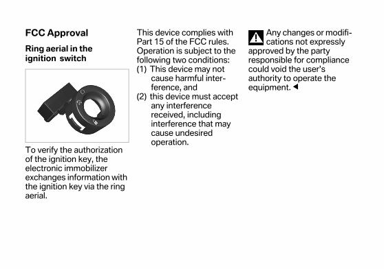
FCC Approval
Ring aerial in the ignition switch
To verify the authorization of the ignition key, the electronic immobilizer exchanges information with the ignition key via the ring aerial.
This device complies with Part 15 of the FCC rules. Operation is subject to the following two conditions:(1) This device may not
cause harmful inter-ference, and
(2) this device must accept any interference received, including interference that may cause undesired operation.
Any changes or modifi-cations not expressly
approved by the party responsible for compliance could void the user’s authority to operate the equipment.
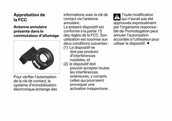
Approbation de la FCC
Antenne annulaire présente dans le commutateur d'allumage
Pour vérifier l'autorisation de la clé de contact, le système d'immobilisation électronique échange des
informations avec la clé de contact via l'antenne annulaire.Le présent dispositif est conforme à la partie 15 des règles de la FCC. Son utilisation est soumise aux deux conditions suivantes :(1) Le dispositif ne
doit pas produire d'interférences nuisibles, et
(2) le dispositif doit pouvoir accepter toutes les interférences extérieures, y compris celles qui pourraient provoquer une activation inopportune.
Toute modification qui n'aurait pas été
approuvée expressément par l'organisme responsa-ble de l'homologation peut annuler l'autorisation accordée à l'utilisateur pour utiliser le dispositif.
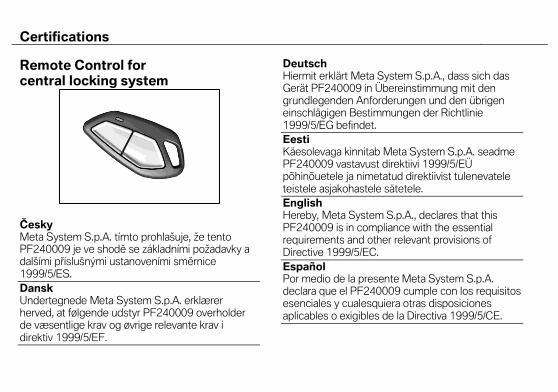
Certifications
Remote Control for central locking system
Česky Meta System S.p.A. tímto prohlašuje, že tento PF240009 je ve shodě se základními požadavky a dalšími příslušnými ustanoveními směrnice 1999/5/ES.
Dansk Undertegnede Meta System S.p.A. erklærer herved, at følgende udstyr PF240009 overholder de væsentlige krav og øvrige relevante krav i direktiv 1999/5/EF.
Deutsch Hiermit erklärt Meta System S.p.A., dass sich das Gerät PF240009 in Übereinstimmung mit den grundlegenden Anforderungen und den übrigen einschlägigen Bestimmungen der Richtlinie 1999/5/EG befindet.
Eesti Käesolevaga kinnitab Meta System S.p.A. seadme PF240009 vastavust direktiivi 1999/5/EÜ põhinõuetele ja nimetatud direktiivist tulenevatele teistele asjakohastele sätetele.
English Hereby, Meta System S.p.A., declares that this PF240009 is in compliance with the essential requirements and other relevant provisions of Directive 1999/5/EC.
Español Por medio de la presente Meta System S.p.A. declara que el PF240009 cumple con los requisitos esenciales y cualesquiera otras disposiciones aplicables o exigibles de la Directiva 1999/5/CE.
Certifications
Ελληνική ΜΕ ΣΗΝ ΠΑΡΟΤΑ Meta System S.p.A. ΔΗΛΩΝΕΙ ΟΣΙ PF240009 ΤΜΜΟΡΥΩΝΕΣΑΙ ΠΡΟ ΣΙ ΟΤΙΩΔΕΙ ΑΠΑΙΣΗΕΙ ΚΑΙ ΣΙ ΛΟΙΠΕ ΦΕΣΙΚΕ ΔΙΑΣΑΞΕΙ ΣΗ ΟΔΗΓΙΑ 1999/5/ΕΚ.
Français Par la présente Meta System S.p.A. déclare que l'appareil PF240009 est conforme aux exigences essentielles et aux autres dispositions pertinentes de la directive 1999/5/CE.
Italiano Con la presente Meta System S.p.A. dichiara che questo PF240009 è conforme ai requisiti essenziali ed alle altre disposizioni pertinenti stabilite dalla direttiva 1999/5/CE.
Latviski Ar šo Meta System S.p.A. deklarē, ka PF240009 atbilst Direktīvas 1999/5/EK būtiskajām prasībām un citiem ar to saistītajiem noteikumiem.
Lietuvių Šiuo Meta System S.p.A. deklaruoja, kad šis PF240009 atitinka esminius reikalavimus ir kitas 1999/5/EB Direktyvos nuostatas.
Nederlands Hierbij verklaart Meta System S.p.A. dat het toestel PF240009 in overeenstemming is met de essentiële eisen en de andere relevante bepalingen van richtlijn 1999/5/EG.
Malti Hawnhekk, Meta System S.p.A., jiddikjara li dan PF240009 jikkonforma mal-ħtiġijiet essenzjali u ma provvedimenti oħrajn relevanti li hemm fid-Dirrettiva 1999/5/EC.
Magyar Alulírott, Meta System S.p.A. nyilatkozom, hogy a PF240009 megfelel a vonatkozó alapvetõ követelményeknek és az 1999/5/EC irányelv egyéb elõírásainak.
Polski Niniejszym Meta System S.p.A. oświadcza, że PF240009 jest zgodny z zasadniczymi wymogami oraz pozostałymi stosownymi postanowieniami Dyrektywy 1999/5/EC.
Português Meta System S.p.A. declara que este PF240009 está conforme com os requisitos essenciais e outras disposições da Directiva 1999/5/CE.
Certifications
Slovensko Meta System S.p.A. izjavlja, da je ta PF240009 v skladu z bistvenimi zahtevami in ostalimi relevantnimi določili direktive 1999/5/ES.
Slovensky Meta System S.p.A. týmto vyhlasuje, že PF240009 spĺňa základné požiadavky a všetky príslušné ustanovenia Smernice 1999/5/ES.
Suomi Meta System S.p.A. vakuuttaa täten että PF240009 tyyppinen laite on direktiivin 1999/5/EY oleellisten vaatimusten ja sitä koskevien direktiivin muiden ehtojen mukainen.
Svenska Härmed intygar Meta System S.p.A. att denna PF240009 står I överensstämmelse med de väsentliga egenskapskrav och övriga relevanta bestämmelser som framgår av direktiv 1999/5/EG.
Íslenska Hér með lýsir Meta System S.p.A. yfir því að PF240009 er í samræmi við grunnkröfur og aðrar kröfur, sem gerðar eru í tilskipun 1999/5/EC.
Norsk Meta System S.p.A. erklærer herved at utstyret PF240009 er i samsvar med de grunnleggende krav og øvrige relevante krav i direktiv 1999/5/EF.
USA, Canada
Product name: TX BMW MR FCC ID: P3O98400 IC:4429A - TXBMWMR
This device complies with Part 15 of the FCC rules. Operation is subject to the following two conditions: (1) This device may not cause harmful interference, and (2) this device must accept any interference received, including interference that may cause undesired operation.
Any changes or modifications not expressly approved by the party
responsible for compliance could void the user’s authority to operate the equipment.
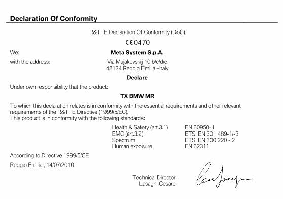
Declaration Of Conformity
R&TTE Declaration Of Conformity (DoC)
0470
We: Meta System S.p.A.
with the address: Via Majakovskij 10 b/c/d/e 42124 Reggio Emilia –Italy
Declare
Under own responsibility that the product:
TX BMW MR
To which this declaration relates is in conformity with the essential requirements and other relevant requirements of the R&TTE Directive (1999/5/EC). This product is in conformity with the following standards:
Health & Safety (art.3.1) EN 60950-1 EMC (art.3.2) ETSI EN 301 489-1/-3 Spectrum ETSI EN 300 220 - 2 Human exposure EN 62311
According to Directive 1999/5/CE
Reggio Emilia , 14/07/2010
Technical Director Lasagni Cesare
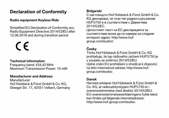
Declaration of Conformity
Radio equipment Keyless Ride Simplified EU Declaration of Conformity acc. Radio Equipment Directive 2014/53/EU after 12.06.2016 and during transition period
Technical information Frequency band: 434,42 MHz Maximum Transmission Power: 10 mW
Manufacturer and Address Manufacturer: Huf Hülsbeck & Fürst GmbH & Co. KG, Steeger Str. 17, 42551 Velbert, Germany
Bŭlgarski С настоящото Huf Hülsbeck & Fürst GmbH & Co. KG декларира, че този тип радиосъоръжение HUF5750 е в съответствие с Директива 2014/53/ЕС. Цялостният текст на ЕС декларацията за съответствие може да се намери на следния интернет адрес: http://www.huf-group.com/eudoc/
Česky Tímto Huf Hülsbeck & Fürst GmbH & Co. KG prohlašuje, že typ rádiového zařízení HUF5750 je v souladu se směrnicí 2014/53/EU. Úplné znění EU prohlášení o shodě je k dispozici na této internetové adrese: http://www.huf-group.com/eudoc
Dansk Hermed erklærer Huf Hülsbeck & Fürst GmbH & Co. KG, at radioudstyrstypen HUF5750 er i overensstemmelse med direktiv 2014/53/EU. EU-overensstemmelseserklæringens fulde tekst kan findes på følgende internetadresse: http://www.huf-group.com/eudoc

Deutsch Hiermit erklärt Huf Hülsbeck & Fürst GmbH & Co. KG, dass der Funkanlagentyp HUF5750 der Richtlinie 2014/53/EU entspricht. Der vollständige Text der EU-Konformitätserklärung ist unter der folgenden Internetadresse verfügbar: http://www.huf-group.com/eudoc
Eesti Käesolevaga deklareerib Huf Hülsbeck & Fürst GmbH & Co. KG, et käesolev raadioseadme tüüp HUF5750 vastab direktiivi 2014/53/EL nõuetele. ELi vastavusdeklaratsiooni täielik tekst on kättesaadav järgmisel internetiaadressil: http://www.huf-group.com/eudoc
English Hereby, Huf Hülsbeck & Fürst GmbH & Co. KG declares that the radio equipment type HUF5750 is in compliance with Directive 2014/53/EU. The full text of the EU declaration of conformity is available at the following internet address: http:// www.huf-group.com/eudoc
Español Por la presente, Huf Hülsbeck & Fürst GmbH & Co. KG declara que el tipo de equipo radioeléctrico HUF5750 es conforme con la Directiva 2014/53/UE. El texto completo de la declaración UE de conformidad está disponible en la dirección Internet siguiente: http://www.huf-group.com/eudoc
Français Le soussigné, Huf Hülsbeck & Fürst GmbH & Co. KG, déclare que l'équipement radioélectrique du type HUF5750 est conforme à la directive 2014/53/UE. Le texte complet de la déclaration UE de conformité est disponible à l'adresse internet suivante: http://www.huf-group.com/eudoc
Hrvatski Huf Hülsbeck & Fürst GmbH & Co. KG ovime izjavljuje da je radijska oprema tipa HUF5750 u skladu s Direktivom 2014/53/EU. Cjeloviti tekst EU izjave o sukladnosti dostupan je na sljedećoj internetskoj adresi: http://www.huf-group.com/eudoc
Íslenska Hér Hülsbeck & Fürst GmbH & Co. KG að radíóbúnaður gerð HUF5750 tilskipunar 2014/53/EB samsvarandi. The fullur texti af ESB-samræmisyfirlýsing er í boði á eftirfarandi veffang: http://www.huf-group.com/eudoc
Italiano Il fabbricante, Huf Hülsbeck & Fürst GmbH & Co. KG, dichiara che il tipo di apparecchiatura radio HUF5750 è conforme alla direttiva 2014/53/UE. Il testo completo della dichiarazione di conformità UE è disponibile al seguente indirizzo Internet: http://www.huf-group.com/eudoc
Latviski Ar šo Huf Hülsbeck & Fürst GmbH & Co. KG deklarē, ka radioiekārta HUF5750 atbilst Direktīvai 2014/53/ES. Pilns ES atbilstības deklarācijas teksts ir pieejams šādā interneta vietnē: http://www.huf-group.com/eudoc
Lietuvių Aš, Huf Hülsbeck & Fürst GmbH & Co. KG, patvirtinu, kad radijo įrenginių tipas HUF5750 atitinka Direktyvą 2014/53/ES. Visas ES atitikties deklaracijos tekstas prieinamas šiuo interneto adresu: http://www.huf-group.com/eudoc
Magyar Huf Hülsbeck & Fürst GmbH & Co. KG igazolja, hogy a HUF5750 típusú rádióberendezés megfelel a 2014/53/EU irányelvnek. Az EU-megfelelőségi nyilatkozat teljes szövege elérhető a következő internetes címen: http://www.huf-group.com/eudoc
Malti B'dan, Huf Hülsbeck & Fürst GmbH & Co. KG, niddikjara li dan it-tip ta' tagħmir tar-radju HUF5750 huwa konformi mad-Direttiva 2014/53/UE. It-test kollu tad-dikjarazzjoni ta' konformità tal-UE huwa disponibbli f'dan l-indirizz tal-Internet li ġej: http://www.huf-group.com/eudoc
Nederlands Hierbij verklaar ik, Huf Hülsbeck & Fürst GmbH & Co. KG, dat het type radioapparatuur HUF5750 conform is met Richtlijn 2014/53/EU. De volledige tekst van de EU-conformiteitsverklaring kan worden geraadpleegd op het volgende internetadres: http://www.huf-group.com/eudoc
Norsk Herved Huf Hülsbeck & Fürst GmbH & Co. KG at radioutstyrstype HUF5750 i direktiv 2014/53/EU tilsvarende. Den fullstendige teksten i EU-erklæring er tilgjengelig på følgende internettadresse: http://www.huf-group.com/eudoc
Polski Huf Hülsbeck & Fürst GmbH & Co. KG niniejszym oświadcza, że typ urządzenia radiowego HUF5750 jest zgodny z dyrektywą 2014/53/UE. Pełny tekst deklaracji zgodności UE jest dostępny pod następującym adresem internetowym: http://www.huf-group.com/eudoc
Português O(a) abaixo assinado(a) Huf Hülsbeck & Fürst GmbH & Co. KG declara que o presente tipo de equipamento de rádio HUF5750 está em conformidade com a Diretiva 2014/53/UE. O texto integral da declaração de conformidade está disponível no seguinte endereço de Internet: http://www.huf-group.com/eudoc
Românesc Prin prezenta, Huf Hülsbeck & Fürst GmbH & Co. KG declară că tipul de echipamente radio HUF5750 este în conformitate cu Directiva 2014/53/UE. Textul integral al declarației UE de conformitate este disponibil la următoarea adresă internet: http://www.huf-group.com/eudoc
Slovensko Huf Hülsbeck & Fürst GmbH & Co. KG potrjuje, da je tip radijske opreme HUF5750 skladen z Direktivo 2014/53/EU. Celotno besedilo izjave EU o skladnosti je na voljo na naslednjem spletnem naslovu: http://www.huf-group.com/eudoc
Slovensky Huf Hülsbeck & Fürst GmbH & Co. KG týmto vyhlasuje, že rádiové zariadenie typu HUF5750 je v súlade so smernicou 2014/53/EÚ. Úplné EÚ vyhlásenie o zhode je k dispozícii na tejto internetovej adrese: http://www.huf-group.com/eudoc
Suomi Huf Hülsbeck & Fürst GmbH & Co. KG vakuuttaa, että radiolaitetyyppi HUF5750 on direktiivin 2014/53/EU mukainen. EU-vaatimustenmukaisuusvakuutuksen täysimittainen teksti on saatavilla seuraavassa internetosoitteessa: http://www.huf-group.com/eudoc
Svenska Härmed försäkrar Huf Hülsbeck & Fürst GmbH & Co. KG att denna typ av radioutrustning HUF5750 överensstämmer med direktiv 2014/53/EU. Den fullständiga texten till EU-försäkran om överensstämmelse finns på följande webbadress: http://www.huf-group.com/eudoc
Ελληνική Με την παρούσα ο/η Huf Hülsbeck & Fürst, δηλώνει ότι ο ραδιοεξοπλισμός HUF5750 πληροί την οδηγία 2014/53/ΕΕ. Το πλήρες κείμενο της δήλωσης συμμόρφωσης ΕΕ διατίθεται στην ακόλουθη ιστοσελίδα στο διαδίκτυο: http://www.huf-group.com/eudoc
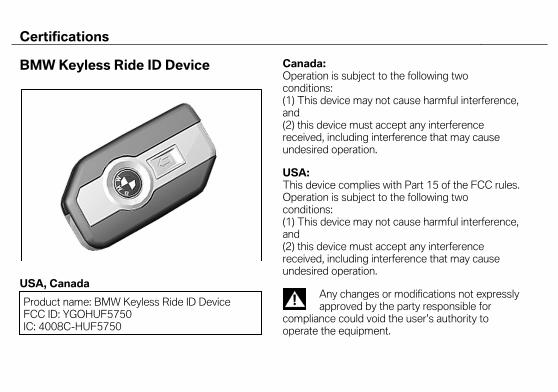
Certifications BMW Keyless Ride ID Device
USA, Canada
Product name: BMW Keyless Ride ID Device FCC ID: YGOHUF5750 IC: 4008C-HUF5750
Canada: Operation is subject to the following two conditions: (1) This device may not cause harmful interference, and (2) this device must accept any interference received, including interference that may cause undesired operation. USA: This device complies with Part 15 of the FCC rules. Operation is subject to the following two conditions: (1) This device may not cause harmful interference, and (2) this device must accept any interference received, including interference that may cause undesired operation.
Any changes or modifications not expressly approved by the party responsible for
compliance could void the user’s authority to operate the equipment.
Declaration Of Conformity We declare under our responsibility that the product
BMW Keyless Ride ID Device (Model: HUF5750) camplies with the appropriate essential requirements of the article 3 of the R&TIE and the other relevant provisions, when used for its intended purpose. Applied Standards:
1. Health and safety requirements contained in article 3 (1) a) • EN 60950-1:2006+A11:2009+A1:2010+A12:2011; Information technology equipment- Safety
2. Protection requirements with respect to electromagnetic compatibility article 3 (1) b) • EN 301 489-1 (V1 .9.2, 09/2011 ), Electromagnetic compatibility and radio spectrum matters (ERM);
Electromagnetic compatibility (EMC) standard for radio equipment and services; Part 1: Common technical requirements
• EN 301 489-3 (V1.4.1, 08/2002) Electromagnetic compatibility and radio spectrum matters (ERM); Electromagnetic compatibility (EMC) standard for radio equipment and services; Part 3: Specific conditions for short range devices (SRD) operating on frequencies between 9 kHz and 40 GHz
3. Means of the efficient use of the radio frequency spectrum article 3 (2) • EN 300 220-1 & -2 (V2.4.1, 05/2012), electromagnetic compatibility and radio spectrum matters (ERM); Short
range devices (SRD); Radio equipment tobe used in the 25 MHz to 1000 MHz frequency range with power Ieveis ranging up to 500 mW; Part 1: Technical characteristics and test methods. Part 2: Harmonized EN covering essential requirements under article 3.2 ofthe R&TIE directive
The product is Iabeted wilh the CE marking:
Velbert, October 15th, 2013
Benjamin A. Müller
Product Development Systems Car Access and Immobilization – Electronics Huf Hülsbeck & Fürst GmbH & Co. KG Steeger Straße 17, D-42551 Velbert
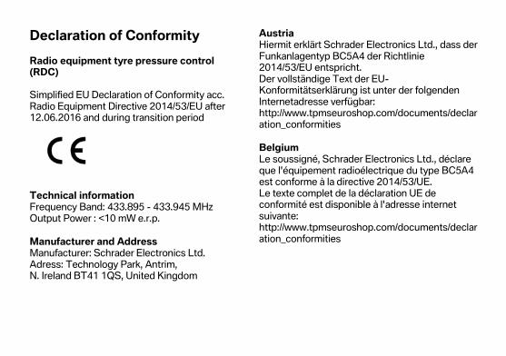
Declaration of Conformity
Radio equipment tyre pressure control (RDC) Simplified EU Declaration of Conformity acc. Radio Equipment Directive 2014/53/EU after 12.06.2016 and during transition period
Technical information Frequency Band: 433.895 - 433.945 MHz Output Power : <10 mW e.r.p.
Manufacturer and Address Manufacturer: Schrader Electronics Ltd. Adress: Technology Park, Antrim, N. Ireland BT41 1QS, United Kingdom
Austria Hiermit erklärt Schrader Electronics Ltd., dass der Funkanlagentyp BC5A4 der Richtlinie 2014/53/EU entspricht. Der vollständige Text der EU-Konformitätserklärung ist unter der folgenden Internetadresse verfügbar: http://www.tpmseuroshop.com/documents/declaration_conformities
Belgium Le soussigné, Schrader Electronics Ltd., déclare que l'équipement radioélectrique du type BC5A4 est conforme à la directive 2014/53/UE. Le texte complet de la déclaration UE de conformité est disponible à l'adresse internet suivante: http://www.tpmseuroshop.com/documents/declaration_conformities
Bulgaria С настоящото Schrader Electronics Ltd. декларира, че този тип радиосъоръжение BC5A4 е в съответствие с Директива 2014/53/ЕС. Цялостният текст на ЕС декларацията за съответствие може да се намери на следния интернет адрес: http://www.tpmseuroshop.com/documents/declaration_conformities
Cyprus Με την παρούσα ο/η Schrader Electronics Ltd., δηλώνει ότι ο ραδιοεξοπλισμός BC5A4 πληροί την οδηγία 2014/53/ΕΕ. Το πλήρες κείμενο της δήλωσης συμμόρφωσης ΕΕ διατίθεται στην ακόλουθη ιστοσελίδα στο διαδίκτυο: http://www.tpmseuroshop.com/documents/declaration_conformities
Czech Republic Tímto Schrader Electronics Ltd. prohlašuje, že typ rádiového zařízení BC5A4 je v souladu se směrnicí 2014/53/EU.
Úplné znění EU prohlášení o shodě je k dispozici na této internetové adrese: http://www.tpmseuroshop.com/documents/declaration_conformities
Germany Hiermit erklärt Schrader Electronics Ltd., dass der Funkanlagentyp BC5A4 der Richtlinie 2014/53/EU entspricht. Der vollständige Text der EU-Konformitätserklärung ist unter der folgenden Internetadresse verfügbar: http://www.tpmseuroshop.com/documents/declaration_conformities
Denmark Hermed erklærer Schrader Electronics Ltd., at radioudstyrstypen BC5A4 er i overensstemmelse med direktiv 2014/53/EU. EU-overensstemmelseserklæringens fulde tekst kan findes på følgende internetadresse: http://www.tpmseuroshop.com/documents/declaration_conformities
Estonia Käesolevaga deklareerib Schrader Electronics Ltd., et käesolev raadioseadme tüüp BC5A4 vastab direktiivi 2014/53/EL nõuetele. ELi vastavusdeklaratsiooni täielik tekst on kättesaadav järgmisel internetiaadressil: http://www.tpmseuroshop.com/documents/declaration_conformities
Spain Por la presente, Schrader Electronics Ltd. declara que el tipo de equipo radioeléctrico BC5A4 es conforme con la Directiva 2014/53/UE. El texto completo de la declaración UE de conformidad está disponible en la dirección Internet siguiente: http://www.tpmseuroshop.com/documents/declaration_conformities
Finland Schrader Electronics Ltd. vakuuttaa, että radiolaitetyyppi BC5A4 on direktiivin 2014/53/EU mukainen. EU-vaatimustenmukaisuusvakuutuksen täysimittainen teksti on saatavilla seuraavassa internetosoitteessa: http://www.tpmseuroshop.com/documents/declaration_conformities
France Le soussigné, Schrader Electronics Ltd., déclare que l'équipement radioélectrique du type BC5A4 est conforme à la directive 2014/53/UE. Le texte complet de la déclaration UE de conformité est disponible à l'adresse internet suivante: http://www.tpmseuroshop.com/documents/declaration_conformities

United Kingdom Hereby, Schrader Electronics Ltd. declares that the radio equipment type BC5A4 is in compliance with Directive 2014/53/EU. The full text of the EU declaration of conformity is available at the following internet address: http://www.tpmseuroshop.com/documents/declaration_conformities
Greece Με την παρούσα ο/η Schrader Electronics Ltd., δηλώνει ότι ο ραδιοεξοπλισμός BC5A4 πληροί την οδηγία 2014/53/ΕΕ. Το πλήρες κείμενο της δήλωσης συμμόρφωσης ΕΕ διατίθεται στην ακόλουθη ιστοσελίδα στο διαδίκτυο: http://www.tpmseuroshop.com/documents/declaration_conformities
Croatia Schrader Electronics Ltd. ovime izjavljuje da je radijska oprema tipa BC5A4 u skladu s Direktivom 2014/53/EU. Cjeloviti tekst EU izjave o sukladnosti dostupan je na sljedećoj internetskoj adresi:
http://www.tpmseuroshop.com/documents/declaration_conformities
Hungary Schrader Electronics Ltd. igazolja, hogy a BC5A4 típusú rádióberendezés megfelel a 2014/53/EU irányelvnek. Az EU-megfelelőségi nyilatkozat teljes szövege elérhető a következő internetes címen: http://www.tpmseuroshop.com/documents/declaration_conformities
Ireland Hereby, Schrader Electronics Ltd. declares that the radio equipment type BC5A4 is in compliance with Directive 2014/53/EU. The full text of the EU declaration of conformity is available at the following internet address: http://www.tpmseuroshop.com/documents/declaration_conformities
Italy Il fabbricante, Schrader Electronics Ltd., dichiara che il tipo di apparecchiatura radio BC5A4 è conforme alla direttiva 2014/53/UE. Il testo completo della dichiarazione di conformità UE è disponibile al seguente indirizzo Internet: http://www.tpmseuroshop.com/documents/declaration_conformities
Lithuania Aš, Schrader Electronics Ltd., patvirtinu, kad radijo įrenginių tipas BC5A4 atitinka Direktyvą 2014/53/ES. Visas ES atitikties deklaracijos tekstas prieinamas šiuo interneto adresu: http://www.tpmseuroshop.com/documents/declaration_conformities
Luxembourg Le soussigné, Schrader Electronics Ltd., déclare que l'équipement radioélectrique du type BC5A4 est conforme à la directive 2014/53/UE.
Le texte complet de la déclaration UE de conformité est disponible à l'adresse internet suivante: http://www.tpmseuroshop.com/documents/declaration_conformities
Latvia Ar šo Schrader Electronics Ltd. deklarē, ka radioiekārta BC5A4 atbilst Direktīvai 2014/53/ES. Pilns ES atbilstības deklarācijas teksts ir pieejams šādā interneta vietnē: http://www.tpmseuroshop.com/documents/declaration_conformities
Malta B'dan, Schrader Electronics Ltd., niddikjara li dan it-tip ta' tagħmir tar-radju BC5A4 huwa konformi mad-Direttiva 2014/53/UE. It-test kollu tad-dikjarazzjoni ta' konformità tal-UE huwa disponibbli f'dan l-indirizz tal-Internet li ġej: http://www.tpmseuroshop.com/documents/declaration_conformities
Netherlands Hierbij verklaar ik, Schrader Electronics Ltd., dat het type radioapparatuur BC5A4 conform is met Richtlijn 2014/53/EU. De volledige tekst van de EU-conformiteitsverklaring kan worden geraadpleegd op het volgende internetadres: http://www.tpmseuroshop.com/documents/declaration_conformities
Poland Schrader Electronics Ltd. niniejszym oświadcza, że typ urządzenia radiowego BC5A4 jest zgodny z dyrektywą 2014/53/UE. Pełny tekst deklaracji zgodności UE jest dostępny pod następującym adresem internetowym: http://www.tpmseuroshop.com/documents/declaration_conformities
Portugal O(a) abaixo assinado(a) Schrader Electronics Ltd. declara que o presente tipo de equipamento de rádio BC5A4 está em conformidade com a Diretiva 2014/53/UE.
O texto integral da declaração de conformidade está disponível no seguinte endereço de Internet: http://www.tpmseuroshop.com/documents/declaration_conformities
Romania Prin prezenta, Schrader Electronics Ltd. declară că tipul de echipamente radio BC5A4 este în conformitate cu Directiva 2014/53/UE. Textul integral al declarației UE de conformitate este disponibil la următoarea adresă internet: http://www.tpmseuroshop.com/documents/declaration_conformities
Sweden Härmed försäkrar Schrader Electronics Ltd. att denna typ av radioutrustning BC5A4 överensstämmer med direktiv 2014/53/EU. Den fullständiga texten till EU-försäkran om överensstämmelse finns på följande webbadress: http://www.tpmseuroshop.com/documents/declaration_conformities
Slovenia Schrader Electronics Ltd. potrjuje, da je tip radijske opreme BC5A4 skladen z Direktivo 2014/53/EU. Celotno besedilo izjave EU o skladnosti je na voljo na naslednjem spletnem naslovu: http://www.tpmseuroshop.com/documents/declaration_conformities
Slovakia Schrader Electronics Ltd. týmto vyhlasuje, že rádiové zariadenie typu BC5A4 je v súlade so smernicou 2014/53/EÚ. Úplné EÚ vyhlásenie o zhode je k dispozícii na tejto internetovej adrese: http://www.tpmseuroshop.com/documents/declaration_conformities
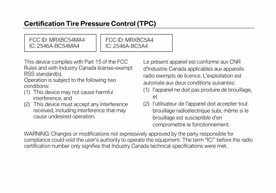
Certification Tire Pressure Control (TPC) This device complies with Part 15 of the FCC Rules and with Industry Canada license-exempt RSS standard(s). Operation is subject to the following two conditions: (1) This device may not cause harmful
interference, and (2) This device must accept any interference
received, including interference that may cause undesired operation.
Le présent appareil est conforme aux CNR d'Industrie Canada applicables aux appareils radio exempts de licence. L'exploitation est autorisée aux deux conditions suivantes: (1) l'appareil ne doit pas produire de brouillage,
et (2) l'utilisateur de l'appareil doit accepter tout
brouillage radioélectrique subi, même si le brouillage est susceptible d'en compromettre le fonctionnement.
WARNING: Changes or modifications not expressively approved by the party responsible for compliance could void the user's authority to operate the equipment. The term “IC:” before the radio certification number only signifies that Industry Canada technical specifications were met.
FCC ID: MRXBC5A4 IC: 2546A-BC5A4
FCC ID: MRXBC54MA4 IC: 2546A-BC54MA4
Declaration of Conformity
Radio equipment intelligent emergency call Simplified EU Declaration of Conformity acc. Radio Equipment Directive 2014/53/EU after 12.06.2016 and during transition period
Technical information Antenna internal: Frequency Band: 880 MHz - 915 MHz Radiated Power [TRP]: < 22 dBm Not acessable by user: Frequency Band: 1710 MHz - 1785 MHz Radiated Power [TRP]: < 26 dBm Frequency Band: 1920 MHz - 1980 MHz Radiated Power [TRP]: < 22 dBm Frequency Band: 880 MHz - 915 MHz Radiated Power [TRP]: < 23 dBm
Manufacturer and Address Manufacturer: Robert Bosch Car Multimedia GmbH Adress: Robert Bosch Str. 200, 31139 Hildesheim, GERMANY
Austria Hiermit erklärt Robert Bosch Car Multimedia GmbH, dass der Funkanlagentyp TPM E-CALL EU der Richtlinie 2014/53/EU entspricht. Der vollständige Text der EU-Konformitätserklärung ist unter der folgenden Internetadresse verfügbar: http://cert.bosch-carmultimedia.net/
Belgium Le soussigné, Robert Bosch Car Multimedia GmbH, déclare que l'équipement radioélectrique du type TPM E-CALL EU est conforme à la directive 2014/53/UE. Le texte complet de la déclaration UE de conformité est disponible à l'adresse internet suivante:http://cert.bosch-carmultimedia.net
Bulgaria С настоящото Robert Bosch Car Multimedia GmbH декларира, че този тип радиосъоръжение TPM E-CALL EU е в съответствие с Директива 2014/53/ЕС. Цялостният текст на ЕС декларацията за съответствие може да се намери на следния интернет адрес: http://cert.bosch-carmultimedia.net/
Cyprus Με την παρούσα ο/η Robert Bosch Car Multimedia GmbH, δηλώνει ότι ο ραδιοεξοπλισμός TPM E-CALL EU πληροί την οδηγία 2014/53/ΕΕ. Το πλήρες κείμενο της δήλωσης συμμόρφωσης ΕΕ διατίθεται στην ακόλουθη ιστοσελίδα στο διαδίκτυο: http://cert.bosch-carmultimedia.net/
Czech Republic Tímto Robert Bosch Car Multimedia GmbH prohlašuje, že typ rádiového zařízení TPM E-CALL EU je v souladu se směrnicí 2014/53/EU. Úplné znění EU prohlášení o shodě je k dispozici na této internetové adrese: http://cert.bosch-carmultimedia.net
Germany Hiermit erklärt Robert Bosch Car Multimedia GmbH, dass der Funkanlagentyp TPM E-CALL EU der Richtlinie 2014/53/EU entspricht. Der vollständige Text der EU-Konformitätserklärung ist unter der folgenden Internetadresse verfügbar: http://cert.bosch-carmultimedia.net
Denmark Hermed erklærer Robert Bosch Car Multimedia GmbH, at radioudstyrstypen TPM E-CALL EU er i overensstemmelse med direktiv 2014/53/EU. EU-overensstemmelseserklæringens fulde tekst kan findes på følgende internetadresse: http://cert.bosch-carmultimedia.net
Estonia Käesolevaga deklareerib Robert Bosch Car Multimedia GmbH, et käesolev raadioseadme tüüp TPM E-CALL EU vastab direktiivi 2014/53/EL nõuetele. ELi vastavusdeklaratsiooni täielik tekst on kättesaadav järgmisel internetiaadressil: http://cert.bosch-carmultimedia.net
Spain Por la presente, Robert Bosch Car Multimedia GmbH declara que el tipo de equipo radioeléctrico TPM E-CALL EU es conforme con la Directiva 2014/53/UE. El texto completo de la declaración UE de conformidad está disponible en la dirección Internet siguiente: http://cert.bosch-carmultimedia.net
Finland Robert Bosch Car Multimedia GmbH vakuuttaa, että radiolaitetyyppi TPM E-CALL EU on direktiivin 2014/53/EU mukainen. EU-vaatimustenmukaisuusvakuutuksen täysimittainen teksti on saatavilla seuraavassa internetosoitteessa: http://cert.bosch-carmultimedia.net
France Le soussigné, Robert Bosch Car Multimedia GmbH, déclare que l'équipement radioélectrique du type TPM E-CALL EU est conforme à la directive 2014/53/UE. Le texte complet de la déclaration UE de conformité est disponible à l'adresse internet suivante: http://cert.bosch-carmultimedia.net
United Kingdom Hereby, Robert Bosch Car Multimedia GmbH declares that the radio equipment type TPM E-CALL EU is in compliance with Directive 2014/53/EU. The full text of the EU declaration of conformity is available at the following internet address: http://cert.bosch-carmultimedia.net
Greece Με την παρούσα ο/η Robert Bosch Car Multimedia GmbH, δηλώνει ότι ο ραδιοεξοπλισμός TPM E-CALL EU πληροί την οδηγία 2014/53/ΕΕ. Το πλήρες κείμενο της δήλωσης συμμόρφωσης ΕΕ διατίθεται στην ακόλουθη ιστοσελίδα στο διαδίκτυο: http://cert.bosch-carmultimedia.net

Croatia Robert Bosch Car Multimedia GmbH ovime izjavljuje da je radijska oprema tipa TPM E-CALL EU u skladu s Direktivom 2014/53/EU. Cjeloviti tekst EU izjave o sukladnosti dostupan je na sljedećoj internetskoj adresi: http://cert.bosch-carmultimedia.net
Hungary Robert Bosch Car Multimedia GmbH igazolja, hogy a TPM E-CALL EU típusú rádióberendezés megfelel a 2014/53/EU irányelvnek. Az EU-megfelelőségi nyilatkozat teljes szövege elérhető a következő internetes címen: http://cert.bosch-carmultimedia.net
Ireland Hereby, Robert Bosch Car Multimedia GmbH declares that the radio equipment type TPM E-CALL EU is in compliance with Directive 2014/53/EU. The full text of the EU declaration of conformity is available at the following internet address: http://cert.bosch-carmultimedia.net
Italy Il fabbricante, Robert Bosch Car Multimedia GmbH, dichiara che il tipo di apparecchiatura radio TPM E-CALL EU è conforme alla direttiva 2014/53/UE. Il testo completo della dichiarazione di conformità UE è disponibile al seguente indirizzo Internet: http://cert.bosch-carmultimedia.net
Lithuania Aš, Robert Bosch Car Multimedia GmbH, patvirtinu, kad radijo įrenginių tipas TPM E-CALL EU atitinka Direktyvą 2014/53/ES. Visas ES atitikties deklaracijos tekstas prieinamas šiuo interneto adresu: http://cert.bosch-carmultimedia.net
Luxembourg Le soussigné, Robert Bosch Car Multimedia GmbH, déclare que l'équipement radioélectrique du type TPM E-CALL EU est conforme à la directive 2014/53/UE. Le texte complet de la déclaration UE de conformité est disponible à l'adresse internet suivante: http://cert.bosch-carmultimedia.net
Latvia Ar šo Robert Bosch Car Multimedia GmbH deklarē, ka radioiekārta TPM E-CALL EU atbilst Direktīvai 2014/53/ES. Pilns ES atbilstības deklarācijas teksts ir pieejams šādā interneta vietnē: http://cert.bosch-carmultimedia.net
Malta B'dan, Robert Bosch Car Multimedia GmbH, niddikjara li dan it-tip ta' tagħmir tar-radju TPM E-CALL EU huwa konformi mad-Direttiva 2014/53/UE. It-test kollu tad-dikjarazzjoni ta' konformità tal-UE huwa disponibbli f'dan l-indirizz tal-Internet li ġej: http://cert.bosch-carmultimedia.net
Netherlands Hierbij verklaar ik, Robert Bosch Car Multimedia GmbH, dat het type radioapparatuur TPM E-CALL EU conform is met Richtlijn 2014/53/EU. De volledige tekst van de EU-conformiteitsverklaring kan worden geraadpleegd op het volgende internetadres: http://cert.bosch-carmultimedia.net
Poland Robert Bosch Car Multimedia GmbH niniejszym oświadcza, że typ urządzenia radiowego TPM E-CALL EU jest zgodny z dyrektywą 2014/53/UE. Pełny tekst deklaracji zgodności UE jest dostępny pod następującym adresem internetowym: http://cert.bosch-carmultimedia.net
Portugal O(a) abaixo assinado(a) Robert Bosch Car Multimedia GmbH declara que o presente tipo de equipamento de rádio TPM E-CALL EU está em conformidade com a Diretiva 2014/53/UE. O texto integral da declaração de conformidade está disponível no seguinte endereço de Internet: http://cert.bosch-carmultimedia.net
Romania Prin prezenta, Robert Bosch Car Multimedia GmbH declară că tipul de echipamente radio TPM E-CALL EU este în conformitate cu Directiva 2014/53/UE. Textul integral al declarației UE de conformitate este disponibil la următoarea adresă internet: http://cert.bosch-carmultimedia.net

Sweden Härmed försäkrar Robert Bosch Car Multimedia GmbH att denna typ av radioutrustning TPM E-CALL EU överensstämmer med direktiv 2014/53/EU. Den fullständiga texten till EU-försäkran om överensstämmelse finns på följande webbadress: http://cert.bosch-carmultimedia.net
Slovenia Robert Bosch Car Multimedia GmbH potrjuje, da je tip radijske opreme TPM E-CALL EU skladen z Direktivo 2014/53/EU. Celotno besedilo izjave EU o skladnosti je na voljo na naslednjem spletnem naslovu: http://cert.bosch-carmultimedia.net
Slovakia Robert Bosch Car Multimedia GmbH týmto vyhlasuje, že rádiové zariadenie typu TPM E-CALL EU je v súlade so smernicou 2014/53/EÚ. Úplné EÚ vyhlásenie o zhode je k dispozícii na tejto internetovej adrese: http://cert.bosch-carmultimedia.net

Declaration of Conformity
Radio equipment anti-theft alarm (DWA) Simplified EU Declaration of Conformity acc. Radio Equipment Directive 2014/53/EU after 12.06.2016 and during transition period
Technical information Frequency Band: 433.05-434.79 MHz Output Power : 10 mW e.r.p.
Manufacturer and Address Manufacturer: Meta System S.p.A. Adress: Via Galimberti 5 42124 Reggio Emilia - Italy –
Austria Hiermit erklärt Meta System S.p.A., dass der Funkanlagentyp TXBMWMR der Richtlinie 2014/53/EU entspricht. Der vollständige Text der EU-Konformitätserklärung ist unter der folgenden Internetadresse verfügbar: https://docs.metasystem.it/
Belgium Le soussigné, Meta System S.p.A., déclare que l'équipement radioélectrique du type TXBMWMR est conforme à la directive 2014/53/UE. Le texte complet de la déclaration UE de conformité est disponible à l'adresse internet suivante:https://docs.metasystem.it/
Bulgaria С настоящото Meta System S.p.A. декларира, че този тип радиосъоръжение TXBMWMR е в съответствие с Директива 2014/53/ЕС. Цялостният текст на ЕС декларацията за съответствие може да се намери на следния интернет адрес: https://docs.metasystem.it/
Cyprus Με την παρούσα ο/η Meta System S.p.A., δηλώνει ότι ο ραδιοεξοπλισμός TXBMWMR πληροί την οδηγία 2014/53/ΕΕ. Το πλήρες κείμενο της δήλωσης συμμόρφωσης ΕΕ διατίθεται στην ακόλουθη ιστοσελίδα στο διαδίκτυο: https://docs.metasystem.it/
Czech Republic Tímto Meta System S.p.A. prohlašuje, že typ rádiového zařízení TXBMWMR je v souladu se směrnicí 2014/53/EU. Úplné znění EU prohlášení o shodě je k dispozici na této internetové adrese: https://docs.metasystem.it/
Germany Hiermit erklärt Meta System S.p.A., dass der Funkanlagentyp TXBMWMR der Richtlinie 2014/53/EU entspricht. Der vollständige Text der EU-Konformitätserklärung ist unter der folgenden Internetadresse verfügbar: https://docs.metasystem.it/
Denmark Hermed erklærer Meta System S.p.A., at radioudstyrstypen TXBMWMR er i overensstemmelse med direktiv 2014/53/EU. EU-overensstemmelseserklæringens fulde tekst kan findes på følgende internetadresse: https://docs.metasystem.it/
Estonia Käesolevaga deklareerib Meta System S.p.A., et käesolev raadioseadme tüüp TXBMWMR vastab direktiivi 2014/53/EL nõuetele. ELi vastavusdeklaratsiooni täielik tekst on kättesaadav järgmisel internetiaadressil: https://docs.metasystem.it/
Spain Por la presente, Meta System S.p.A. declara que el tipo de equipo radioeléctrico TXBMWMR es conforme con la Directiva 2014/53/UE. El texto completo de la declaración UE de conformidad está disponible en la dirección Internet siguiente: https://docs.metasystem.it/

Finland Meta System S.p.A. vakuuttaa, että radiolaitetyyppi TXBMWMR on direktiivin 2014/53/EU mukainen. EU-vaatimustenmukaisuusvakuutuksen täysimittainen teksti on saatavilla seuraavassa internetosoitteessa: https://docs.metasystem.it/
France Le soussigné, Meta System S.p.A., déclare que l'équipement radioélectrique du type TXBMWMR est conforme à la directive 2014/53/UE. Le texte complet de la déclaration UE de conformité est disponible à l'adresse internet suivante: https://docs.metasystem.it/
United Kingdom Hereby, Meta System S.p.A. declares that the radio equipment type TXBMWMR is in compliance with Directive 2014/53/EU. The full text of the EU declaration of conformity is available at the following internet address: https://docs.metasystem.it/
Greece Με την παρούσα ο/η Meta System S.p.A., δηλώνει ότι ο ραδιοεξοπλισμός TXBMWMR πληροί την οδηγία 2014/53/ΕΕ. Το πλήρες κείμενο της δήλωσης συμμόρφωσης ΕΕ διατίθεται στην ακόλουθη ιστοσελίδα στο διαδίκτυο: https://docs.metasystem.it/
Croatia Meta System S.p.A. ovime izjavljuje da je radijska oprema tipa TXBMWMR u skladu s Direktivom 2014/53/EU. Cjeloviti tekst EU izjave o sukladnosti dostupan je na sljedećoj internetskoj adresi: https://docs.metasystem.it/
Hungary Meta System S.p.A. igazolja, hogy a TXBMWMR típusú rádióberendezés megfelel a 2014/53/EU irányelvnek. Az EU-megfelelőségi nyilatkozat teljes szövege elérhető a következő internetes címen: https://docs.metasystem.it/
Ireland Hereby, Meta System S.p.A. declares that the radio equipment type TXBMWMR is in compliance with Directive 2014/53/EU. The full text of the EU declaration of conformity is available at the following internet address: https://docs.metasystem.it/
Italy Il fabbricante, Meta System S.p.A., dichiara che il tipo di apparecchiatura radio TXBMWMR è conforme alla direttiva 2014/53/UE. Il testo completo della dichiarazione di conformità UE è disponibile al seguente indirizzo Internet: https://docs.metasystem.it/
Lithuania Aš, Meta System S.p.A., patvirtinu, kad radijo įrenginių tipas TXBMWMR atitinka Direktyvą 2014/53/ES. Visas ES atitikties deklaracijos tekstas prieinamas šiuo interneto adresu: https://docs.metasystem.it/
Luxembourg Le soussigné, Meta System S.p.A., déclare que l'équipement radioélectrique du type TXBMWMR est conforme à la directive 2014/53/UE. Le texte complet de la déclaration UE de conformité est disponible à l'adresse internet suivante: https://docs.metasystem.it/
Latvia Ar šo Meta System S.p.A. deklarē, ka radioiekārta TXBMWMR atbilst Direktīvai 2014/53/ES. Pilns ES atbilstības deklarācijas teksts ir pieejams šādā interneta vietnē: https://docs.metasystem.it/
Malta B'dan, Meta System S.p.A., niddikjara li dan it-tip ta' tagħmir tar-radju TXBMWMR huwa konformi mad-Direttiva 2014/53/UE. It-test kollu tad-dikjarazzjoni ta' konformità tal-UE huwa disponibbli f'dan l-indirizz tal-Internet li ġej: https://docs.metasystem.it/
Netherlands Hierbij verklaar ik, Meta System S.p.A., dat het type radioapparatuur TXBMWMR conform is met Richtlijn 2014/53/EU. De volledige tekst van de EU-conformiteitsverklaring kan worden geraadpleegd op het volgende internetadres: https://docs.metasystem.it/
Poland Meta System S.p.A. niniejszym oświadcza, że typ urządzenia radiowego TXBMWMR jest zgodny z dyrektywą 2014/53/UE. Pełny tekst deklaracji zgodności UE jest dostępny pod następującym adresem internetowym: https://docs.metasystem.it/
Portugal O(a) abaixo assinado(a) Meta System S.p.A. declara que o presente tipo de equipamento de rádio TXBMWMR está em conformidade com a Diretiva 2014/53/UE. O texto integral da declaração de conformidade está disponível no seguinte endereço de Internet: https://docs.metasystem.it/
Romania Prin prezenta, Meta System S.p.A. declară că tipul de echipamente radio TXBMWMR este în conformitate cu Directiva 2014/53/UE. Textul integral al declarației UE de conformitate este disponibil la următoarea adresă internet: https://docs.metasystem.it/
Sweden Härmed försäkrar Meta System S.p.A. att denna typ av radioutrustning TXBMWMR överensstämmer med direktiv 2014/53/EU. Den fullständiga texten till EU-försäkran om överensstämmelse finns på följande webbadress: https://docs.metasystem.it/
Slovenia Meta System S.p.A. potrjuje, da je tip radijske opreme TXBMWMR skladen z Direktivo 2014/53/EU. Celotno besedilo izjave EU o skladnosti je na voljo na naslednjem spletnem naslovu: https://docs.metasystem.it/
Slovakia Meta System S.p.A. týmto vyhlasuje, že rádiové zariadenie typu TXBMWMR je v súlade so smernicou 2014/53/EÚ. Úplné EÚ vyhlásenie o zhode je k dispozícii na tejto internetovej adrese: https://docs.metasystem.it/
Declaration of Conformity
Radio equipment audio system Simplified EU Declaration of Conformity acc. Radio Equipment Directive 2014/53/EU after 12.06.2016 and during transition period
Technical information Frequency Band: 2,400 GHz Output Power : 4 dBm
Manufacturer and Address Manufacturer: Alpine Electronics Inc Adress: 20-1, Yoshima Industrial Park, Iwaki, Fukushima 970-1192 Phone: + 81246 36 4111
Austria Hiermit erklärt Alpine Electronics Inc., dass der Funkanlagentyp MRBE001A der Richtlinie 2014/53/EU entspricht. Der vollständige Text der EU-Konformitätserklärung ist unter der folgenden Internetadresse verfügbar: http://www.alpine.com/e/research/
Belgium Le soussigné, Alpine Electronics Inc., déclare que l'équipement radioélectrique du type MRBE001A est conforme à la directive 2014/53/UE. Le texte complet de la déclaration UE de conformité est disponible à l'adresse internet suivante:http://www.alpine.com/e/research/
Bulgaria С настоящото Alpine Electronics Inc. декларира, че този тип радиосъоръжение MRBE001A е в съответствие с Директива 2014/53/ЕС. Цялостният текст на ЕС декларацията за съответствие може да се намери на следния интернет адрес: http://www.alpine.com/e/research/
Cyprus Με την παρούσα ο/η Alpine Electronics Inc., δηλώνει ότι ο ραδιοεξοπλισμός MRBE001A πληροί την οδηγία 2014/53/ΕΕ. Το πλήρες κείμενο της δήλωσης συμμόρφωσης ΕΕ διατίθεται στην ακόλουθη ιστοσελίδα στο διαδίκτυο: http://www.alpine.com/e/research/
Czech Republic Tímto Alpine Electronics Inc. prohlašuje, že typ rádiového zařízení MRBE001A je v souladu se směrnicí 2014/53/EU. Úplné znění EU prohlášení o shodě je k dispozici na této internetové adrese: http://www.alpine.com/e/research/
Germany Hiermit erklärt Alpine Electronics Inc., dass der Funkanlagentyp MRBE001A der Richtlinie 2014/53/EU entspricht. Der vollständige Text der EU-Konformitätserklärung ist unter der folgenden Internetadresse verfügbar: http://www.alpine.com/e/research/
Denmark Hermed erklærer Alpine Electronics Inc., at radioudstyrstypen MRBE001A er i overensstemmelse med direktiv 2014/53/EU. EU-overensstemmelseserklæringens fulde tekst kan findes på følgende internetadresse: http://www.alpine.com/e/research/
Estonia Käesolevaga deklareerib Alpine Electronics Inc., et käesolev raadioseadme tüüp MRBE001A vastab direktiivi 2014/53/EL nõuetele. ELi vastavusdeklaratsiooni täielik tekst on kättesaadav järgmisel internetiaadressil: http://www.alpine.com/e/research/
Spain Por la presente, Alpine Electronics Inc. declara que el tipo de equipo radioeléctrico MRBE001A es conforme con la Directiva 2014/53/UE. El texto completo de la declaración UE de conformidad está disponible en la dirección Internet siguiente: http://www.alpine.com/e/research/
Finland Alpine Electronics Inc. vakuuttaa, että radiolaitetyyppi MRBE001A on direktiivin 2014/53/EU mukainen. EU-vaatimustenmukaisuusvakuutuksen täysimittainen teksti on saatavilla seuraavassa internetosoitteessa: http://www.alpine.com/e/research/
France Le soussigné, Alpine Electronics Inc., déclare que l'équipement radioélectrique du type MRBE001A est conforme à la directive 2014/53/UE. Le texte complet de la déclaration UE de conformité est disponible à l'adresse internet suivante: http://www.alpine.com/e/research/
United Kingdom Hereby, Alpine Electronics Inc. declares that the radio equipment type MRBE001A is in compliance with Directive 2014/53/EU. The full text of the EU declaration of conformity is available at the following internet address: http://www.alpine.com/e/research/
Greece Με την παρούσα ο/η Alpine Electronics Inc., δηλώνει ότι ο ραδιοεξοπλισμός MRBE001A πληροί την οδηγία 2014/53/ΕΕ. Το πλήρες κείμενο της δήλωσης συμμόρφωσης ΕΕ διατίθεται στην ακόλουθη ιστοσελίδα στο διαδίκτυο: http://www.alpine.com/e/research/
Croatia Alpine Electronics Inc. ovime izjavljuje da je radijska oprema tipa MRBE001A u skladu s Direktivom 2014/53/EU. Cjeloviti tekst EU izjave o sukladnosti dostupan je na sljedećoj internetskoj adresi: http://www.alpine.com/e/research/
Hungary Alpine Electronics Inc. igazolja, hogy a MRBE001A típusú rádióberendezés megfelel a 2014/53/EU irányelvnek. Az EU-megfelelőségi nyilatkozat teljes szövege elérhető a következő internetes címen: http://www.alpine.com/e/research/

Ireland Hereby, Alpine Electronics Inc. declares that the radio equipment type MRBE001A is in compliance with Directive 2014/53/EU. The full text of the EU declaration of conformity is available at the following internet address: http://www.alpine.com/e/research/
Italy Il fabbricante, Alpine Electronics Inc., dichiara che il tipo di apparecchiatura radio MRBE001A è conforme alla direttiva 2014/53/UE. Il testo completo della dichiarazione di conformità UE è disponibile al seguente indirizzo Internet: http://www.alpine.com/e/research/
Lithuania Aš, Alpine Electronics Inc., patvirtinu, kad radijo įrenginių tipas MRBE001A atitinka Direktyvą 2014/53/ES. Visas ES atitikties deklaracijos tekstas prieinamas šiuo interneto adresu: http://www.alpine.com/e/research/
Luxembourg Le soussigné, Alpine Electronics Inc., déclare que l'équipement radioélectrique du type MRBE001A est conforme à la directive 2014/53/UE. Le texte complet de la déclaration UE de conformité est disponible à l'adresse internet suivante: http://www.alpine.com/e/research/
Latvia Ar šo Alpine Electronics Inc. deklarē, ka radioiekārta MRBE001A atbilst Direktīvai 2014/53/ES. Pilns ES atbilstības deklarācijas teksts ir pieejams šādā interneta vietnē: http://www.alpine.com/e/research/
Malta B'dan, Alpine Electronics Inc., niddikjara li dan it-tip ta' tagħmir tar-radju MRBE001A huwa konformi mad-Direttiva 2014/53/UE. It-test kollu tad-dikjarazzjoni ta' konformità tal-UE huwa disponibbli f'dan l-indirizz tal-Internet li ġej: http://www.alpine.com/e/research/
Netherlands Hierbij verklaar ik, Alpine Electronics Inc., dat het type radioapparatuur MRBE001A conform is met Richtlijn 2014/53/EU. De volledige tekst van de EU-conformiteitsverklaring kan worden geraadpleegd op het volgende internetadres: http://www.alpine.com/e/research/
Poland Alpine Electronics Inc. niniejszym oświadcza, że typ urządzenia radiowego MRBE001A jest zgodny z dyrektywą 2014/53/UE. Pełny tekst deklaracji zgodności UE jest dostępny pod następującym adresem internetowym: http://www.alpine.com/e/research/
Portugal O(a) abaixo assinado(a) Alpine Electronics Inc. declara que o presente tipo de equipamento de rádio MRBE001A está em conformidade com a Diretiva 2014/53/UE. O texto integral da declaração de conformidade está disponível no seguinte endereço de Internet: http://www.alpine.com/e/research/
Romania Prin prezenta, Alpine Electronics Inc. declară că tipul de echipamente radio MRBE001A este în conformitate cu Directiva 2014/53/UE. Textul integral al declarației UE de conformitate este disponibil la următoarea adresă internet: http://www.alpine.com/e/research/
Sweden Härmed försäkrar Alpine Electronics Inc. att denna typ av radioutrustning MRBE001A överensstämmer med direktiv 2014/53/EU. Den fullständiga texten till EU-försäkran om överensstämmelse finns på följande webbadress: http://www.alpine.com/e/research/
Slovenia Alpine Electronics Inc. potrjuje, da je tip radijske opreme MRBE001A skladen z Direktivo 2014/53/EU. Celotno besedilo izjave EU o skladnosti je na voljo na naslednjem spletnem naslovu: http://www.alpine.com/e/research/
Slovakia Alpine Electronics Inc. týmto vyhlasuje, že rádiové zariadenie typu MRBE001A je v súlade so smernicou 2014/53/EÚ. Úplné EÚ vyhlásenie o zhode je k dispozícii na tejto internetovej adrese: http://www.alpine.com/e/research/
Certifications
United Arab Emirates
Product name: MCR, Model name: K48/K52/K61
TRA REGISTERED No: 0027793/10 DEALER No: 0014517/08
USA, Canada FCC WARNING Changes or modifications not expressly approved by the party responsible for compliance could void the user’s authority to operate the equipment. NOTICE This equipment complies with FCC/IC radiation exposure limits set forth for uncontrolled equipment and meets the FCC radio frequency (RF) Exposure Guidelines in Supplement C to OET65 and RSS-102 of the IC radio frequency (RF) Exposure rules. This equipment has very low levels of RF energy that it deemed to comply without maximum permissive exposure evaluation (MPE). But it is desirable that it should be installed and operated with at least 20cm and more between the radiator and person’s body (excluding extremities: hands, wrists, feet and ankles).
Certifications
Brazil
Product name: MCR, Model name: K48/K52/K61
Este equipamento opera em caráter secundário, isto é, não tem direito a proteção contra interferência prejudicial, mesmo de estações do mesmo tipo, e não pode causar interferência a sistemas operando em caráter primário.
Mexico COFETEL RCPALPF10-0522 Product name: MCR, Model name: K48/K52/K61 Este equipo opera a titulo secundario, consecuentemente, debe aceptar interferencias perjudiciales incluyendo equipos de la misma clase y puede no causar interferencias a sistemas operando a titulo primario.
Argentina CNC-ID 16-8765
Malaysia Placeholder for certification label:
Certifications
South Korea
N25-MRBE002A
Name of applicant: Alpine Eletrconics Inc. Japan Code of applicant: N25 Model name: MCR K48/K52/K61 Produced by: Alpine Electronics Manufacturing Of Europe, Ltd. Vendel Park, Budai utca 1, H-2051 Biatorbagy, Hungary
Thailand This telecommunication equipment conforms to technical standard NTC technical.
Singapore
Taiwan
第十二條
經型式認證合格之低功率射頻電機,非經許可,公司、商
號或使用者均不得擅自變更頻
率、加大功率或變更原設計之特性及功能。
第十四條
低功率射頻電機之使用不得影響飛航安全及干擾合法通信
;經發現有干擾現象時,應立即
停用,並改善至無干擾時方得繼續使用。
前項合法通信,指依電信法規定作業之無線電通信。
低功率射頻電機須忍受合法通信或工業、科學及醫療用電
波輻射性電機設備之干擾。
Complies with IDA Standard DB105286
Certifications
Serbia
China 第十三条 进口和生产厂商在其产品的说明书或使用手册中,应刊印下
述有关内容:
1.标明附件中所规定的技术指标和使用范围,说明所有控
制、调整及开关等使用方法:
使用频率:2.4 - 2.4835 GHz
等效全向辐射功率(EIRP):天线增益<10dBi:
≤100 mW 或≤20 dBm
最大功率谱密度:
天线增益<10dBi时:≤20 dBm / MHz(EIRP)
载频容限:20 ppm
帯外发射功率(在2.4-2.4835GHz頻段以外)
≤-80 dBm / Hz (EIRP)
杂散发射(辐射)功率(对应载波±2.5倍信道带宽
以外):
≤-36 dBm / 100 kHz (30 - 1000 MHz)
≤-33 dBm / 100 kHz (2.4 - 2.4835 GHz)
≤-40 dBm / 1 MHz (3.4 - 3.53 GHz)
≤-40 dBm / 1 MHz (5.725 - 5.85 GHz)
≤-30 dBm / 1 MHz (其它1 - 12.75 GHz)
2.不得擅自更改发射频率、加大发射功率(包括额外加装射
频功率放大器),不得擅自外接天线或改用其它发射天线;
3.使用时不得对各种合法的无线电通信业务产生有害干;
一旦发现有干扰现象时,应立即停止使用,并采取措施消
除干扰后方可继续使用;
4.使用微功率无线电设备,必须忍受各种无线电业务的干
扰或工业、科学及医疗应用设备的辐射干扰;
5.不得在飞机和机场附近使用。
AAbbreviations and symbols, 6ABS
Engineering details, 150Indicator and warning lights, 53Self-diagnosis, 137
Accessoriesgeneral notes, 194
Adaptive Headlight, 160Ambient temperature
Outside temperaturewarning, 44Reading, 44
Anti-theft alarmIndicator light, 29operating, 83Warning, 52
Audio systemPosition on the vehicle, 22Select audio source, 104Switching off, 104Switching on, 104
Auxiliary headlightsoperating, 73
Average valuesreset, 81
BBattery
charging battery whenconnected, 187Charging battery whendisconnected, 188install, 189Maintenance instructions, 186Position on the vehicle, 23removing, 188Technical data, 223Warning for battery chargecurrent, 52Warning for battery voltagelow, 51
BluetoothAdditional functions, 127Pairing, 125switching on, 124
Brake fluidChecking fluid level, front, 168Checking fluid level, rear, 169Reservoir, front, 21Reservoir, rear, 21
Brake padsChecking front, 166Checking rear, 166Running in, 139
Brake temperatureWarning, 56
BrakesABS Pro in detail, 152ABS Pro, 141Adjusting handlebar lever, 132Checking function, 165Checking operation, 165Safety information, 139Technical data, 220
CCare
Chrome, 207Paintwork preservation, 208
15305
z Ind
ex
Casesoperate, 195
Central lockingoperating, 92Warning for lock status, 53
Chassis and suspensionTechnical data, 219
ClockAdjusting, 80
ClutchAdjusting handlebar lever, 131Checking operation, 170Technical data, 217
Communication systems, 124Additional functions, 127
CoolantChecking fill level, 170Fill-level indicator, 21Warning for overtemperat-ure, 45
Cruise-control systemControl, 24operating, 89
Currency, 8
DDamping
Adjusting, 87Date
Adjusting, 80Daytime riding lights
automatic daytime ridinglight, 75Control, 24manual daytime riding light, 74
Diagnostic connectorLoosen, 191secure, 192
DimensionsTechnical data, 225
Distance recordersoperating, 82
DTCControl, 24Engineering details, 153operating, 87Self-diagnosis, 138Warning, 53
DWATechnical data, 224
EElectrical system
Technical data, 223Emergency call
Automatically in the event of alight fall, 69Automatically in the event of asevere fall, 70Language, 68Notes, 13operate, 68Reading, 58
Emergency off switch (killswitch), 25, 26operate, 67
EngineIndicator light for engineelectronics, 46Malfunction indicator lamp, 45starting, 136Technical data, 216
Engine oilChecking fill level, 164Electronic oil-level check, 46Filler neck, 21
15306
z Ind
ex

Oil dipstick, 21Technical data, 216Topping up, 165Warning for engine oil level, 47
Equipment, 7ESA
Control, 24Engineering details, 155operating, 87
External audio devicesconnecting, 103, 119Data memory, 121iPod, 121MP3 player, 122operate, 122Random playback, 123USB stick, 121
FFinal drive
Technical data, 218Frame
Technical data, 219Front-wheel stand
installing, 162
FuelFiller neck, 19Fuel grade, 142refuelling, 143refuelling with KeylessRide, 144Technical data, 215
Fuel reserveRange, 54Warning, 55
FusesPosition on the vehicle, 23replacing, 190Technical data, 223
GGeneral views
Display with satellite radio, 114Indicator and warning lights, 32Instrument panel, 29Left multifunction switch, 24left side of vehicle, 19Multifunction display, 35Right multifunction switch, 25,26
right side of vehicle, 21Underneath the seat, 23
Ground lightingoperate, 73
HHandlebar operating panel
Position on the vehicle, 22Hazard warning flashers
Control, 24operating, 75
HeadlightAdjusting right-hand/left-handtraffic, 72Headlight beam-throwadjustment, 19Warning for driving on left/driving on right, 50Warning for unknownposition, 50
Heated handlebar gripsoperating, 96
15307
z Ind
ex
Hill Start Control Pro, 159cannot be activated, 56Engineering details, 159Indicator and warning lights, 55,56operating, 91
Horn, 24
IIgnition
switching off, 63switching on, 62
ImmobiliserSpare key, 66Warning, 44
Indicator lights, 29DTC, 53Overview, 32
Instrument clusterAmbient-light brightnesssensor, 29Overview, 29
iPod, 121connecting, 119
JJump-starting, 185
KKeyless Ride
Battery of the radio-operatedkey is empty or loss of theradio-operated key, 65Engaging steering lock, 63Fuel filler cap, unlocking, 144Switching off ignition, 64Switching on ignition, 64Warning, 44, 45
Keys, 62, 63
LLighting
High-beam headlight, 179Replace LED flashing turnindicators, 184Replacing bulb for low-beamheadlight, 183Replacing LED additionalheadlights, 184Replacing LED rear light, 184
Technical data, 223Warning for bulb failure, 50
Lightsautomatic daytime ridinglight, 75Control, 24Headlight flasher, operating, 72High-beam headlight,operating, 72Low-beam headlight, 71manual daytime riding light, 74Parking lights, operating, 72Side light, 71
LoudspeakerRelationship withBluetooth, 105switching off, 107
LuggageInstructions for loading, 134
15308
z Ind
ex

MMaintenance
General instructions, 162Maintenance schedule, 235
Maintenance confirmations, 236Maintenance intervals, 231Malfunction indicator lamp, 45Mirrors
Adjusting, 130Mobility services, 231Motorcycle
care, 205cleaning, 205lashing, 146parking, 141
MP3 player, 122Adjust the volume, 108connecting, 119
Multifunction display, 22, 29Control, 24Meaning of symbols, 33operating, 76Overview, 35, 102Settings, 80
Multifunction switchOverview, left side, 24Overview, right side, 25, 26
NNavigation devices
install, 200operate, 202remove, 201
OOn-board computer
operating, 81Operating panel
Overview, 27Position on the vehicle, 22
PPairing, 125Parking, 141Power socket
Notes on use, 194Position on the vehicle, 21
Pre-Ride-Check, 137
RRadio
Calling up stations saved inmemory, 111Select the frequency band, 109
Radio Data System RDS, 113RDC
Adhesive label for rim, 173Engineering details, 157Reading, 47Warnings, 48
Refuelling, 143Fuel grade, 142with Keyless Ride, 144
Regional broadcasts, 113Remote control
registration, 94Replacing battery, 66, 95synchronising, 95
Rev. counter, 29reverser, 70
Control, 24Rider's seat
Height adjustment, 23
15309
z Ind
ex
Riding modeadjusting, 88Engineering details, 155
Running in, 138
SSafety instructions
for brakes, 139for riding, 134
Satellite radioAvailability, 114Calling up channel saved inmemory, 117Channel, selecting, 115Channel, subscribing to, 114Display overview, 114Information in the display, 115Save channel, 116Signal strength, 114Status reports, 119View ESN, 119
Seatinstalling, 98removing, 98Unlocking, 19
Seat heatingoperating, 97
Service, 230Service history, 230Warning, 57
Service-due indicator, 56Shift assistant, 158
Engineering details, 158slipstream deflector
Adjusting, 131Spark plugs
Technical data, 223Speedometer, 29Spring preload
Adjusting, 87Starting, 136
Control, 25, 26Steering lock
Locking, 62Stowage compartment, 103
operating, 99Position on the vehicle, 19, 21
SymbolsMeaning, 33
TTechnical data
Anti-theft alarm, 224Battery, 223Brakes, 220Bulbs, 223Clutch, 217Dimensions, 225Electrical system, 223Engine, 216Engine oil, 216Final drive, 218Frame, 219Fuel, 215General notes, 7Spark plugs, 223Standards, 7Suspension, 219Transmission, 218Weights, 226Wheels and tyres, 221
Tone settings, 107Toolkit
Contents, 162Position on the vehicle, 23
15310
z Ind
ex
Topcaseoperate, 197
Torques, 213Traffic channel, 113
Adjusting volume, 107Cancel, 107
TransmissionTechnical data, 218
Troubleshooting chart, 212Turn indicators
Control, 24operating, 76
Type platePosition on the vehicle, 21
TyresChecking tread depth, 171Checking tyre pressure, 171Pressures, 222Recommendation, 172Running in, 139Table of tyre pressures, 23Technical data, 221
UUSB stick, 121, 122, 123
connecting, 119
VVehicle
Laying up, 208restoring to use, 209
Vehicle Identification NumberPosition on the vehicle, 21
VolumeAdapt to speed, 108Adjusting, 105Muting, 106
WWarning indicator lights
ABS, 53Anti-theft alarm, 52Battery charge current, 52Brake temperature, 56Bulb defect, 50Central locking, 53Coolant temperature, 45Electronic immobiliser, 44Engine electronics, 46
Engine oil level, 47Fuel reserve, 55Headlight in unknownposition, 50Headlight setting, driving onleft/driving on right, 50Hill Start Control Pro, 55, 56Malfunction indicator lamp, 45Mode of presentation, 36Outside temperaturewarning, 44RDC, 48Service, 57Undervoltage, 51
Warning lights, 29Overview, 32
Warnings, overview, 37Weights
Payload table, 23Technical data, 226
WheelsChange of size, 172Checking rims, 171Installing front wheel, 175Installing rear wheel, 178
15311
z Ind
ex
Remove the front wheel, 173Remove the rear wheel, 177Technical data, 221
WindscreenAdjusting, 130Control, 24
15312
z Ind
ex

15313
z Ind
ex
Details described or illustratedin this booklet may differ fromthe vehicle's actual specificationas purchased, the accessoriesfitted or the national-market spe-cification. No claims will be en-tertained as a result of such dis-crepancies.Dimensions, weights, fuel con-sumption and performance dataare quoted to the customary tol-erances.The right to modify designs,equipment and accessories isreserved.Errors and omissions excepted.
© 2019 Bayerische MotorenWerke Aktiengesellschaft80788 Munich, GermanyNot to be reproduced by anymeans whatsoever, wholly orin part, without the written per-mission of BMW Motorrad, AfterSales.
Original rider’s manual, printed inGermany.
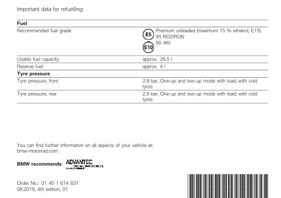
Important data for refuelling:
Fuel
Recommended fuel grade Premium unleaded (maximum 15 % ethanol, E15)95 ROZ/RON90 AKI
Usable fuel capacity approx. 26.5 l
Reserve fuel approx. 4 l
Tyre pressure
Tyre pressure, front 2.9 bar, One-up and two-up mode with load; with coldtyres
Tyre pressure, rear 2.9 bar, One-up and two-up mode with load; with coldtyres
You can find further information on all aspects of your vehicle at:bmwmotorrad.com
BMW recommends
Order No.: 01 40 1 614 83108.2019, 4th edition, 01
*01401614831**01401614831**01401614831*