rick significant changes to 5 7.ppt - connecticut
TRANSCRIPT

4/30/2014
1
Introduction to the Significant Changesto the 2008 & 2011
National Electric Code
1
Welcome
• InstructorRick Massicott
2
House Keeping
• Emergency Exits
• Please silence cell phones

4/30/2014
2
DISCLAIMERThe views expressed here are not the views of the following:
• IBEW Local 90
• IBEW
• NECA
• CT Dept. of Consumer Protection
• CT Dept. of Labor• CT Dept of Construction
• NJATC
• NFPA
• NEMA
• ANSI
• IAEI
• UL
• CT Dept. of Construction Services
• CT General Assembly• International Code
Council• Any Manufacturer• Rick’s Wife
Which Edition
• Significant changes to the 2008 NEC will be represented with the 2008 NEC in the upper
• Significant changes to the 2011 NEC will be represented with the 2011 NEC in the upper
left corner of the slide. left corner of the slide.
How Many Changes Since 2005 ?
Proposals
2008 3,688
Comments
2,349,
2011 5,016
Total 8,704
2,3492,910
5,259
6

4/30/2014
3
500.2 Definitions: Combustible Dust
• New definition for “Combustible Dust” added at 500.2
• Definition extracted from NFPA 499 (Recommended Practice for the Classification of Combustible Dusts and of Hazardous Locations for Electrical Installations in Chemical Process
)Areas)
• This definition for combustible dust has been added or revised in a number of other NFPA documents
• Previous editions of the Code did not have a definition included that mentioned dust size and diameter
• New definition will serve to aid the designer or engineer in determining classification of area
4/30/2014
4/30/2014
4
4/30/2014

4/30/2014
5
4/30/2014
511.2 and 511.3Commercial Garages, Repair and Storage
• Two new definitions of the terms major repair garage and minor repair garage have been added to create a new 511.2.
4/30/2014
• Existing 511.3(A) and (B) have been rearranged in a more logical layout under the single heading of Area Classification.

4/30/2014
6
511.2 Major Repair Garage
• A building or portions of a building where major repairs, such as engine overhauls, painting, body and fender work, and repairs that require draining of the motor vehicle fuel
4/30/2014
that require draining of the motor vehicle fuel tank are performed on motor vehicles, including associated floor space used for offices, parking, or showrooms.
511.2 Minor Repair Garage
• A building or portions of a building used for lubrication, inspection, and minor automotive maintenance work, such as engine tune‐ups, replacement of parts fluid changes (e g oil
4/30/2014
replacement of parts, fluid changes (e.g., oil, antifreeze, transmission fluid, brake fluid, air conditioning refrigerants), brake system repairs, tire rotation, and similar routine maintenance work, including associated floor space used for offices, parking, or showrooms.
Table 514.3(B)(1) Class I LocationsMotor Fuel Dispensing Facilities
• Revisions to Table 514.3(B)(1) have been implemented to coordinate with Table 8.3.1 of NFPA 30A (Code for Motor Fuel Dispensing Facilities and Repair Garages)
• This revision avoids conflicts between the NEC and NFPA 30A and recognizes the importance of consistent30A and recognizes the importance of consistent information
• Table 514.3(B)(1) in the NEC and Table 8.3.1 in NFPA 30A are now identical in their respective new editions
• Revised Table 514.3(B)(1) more clearly incorporates the Zone classification system

4/30/2014
7
514.8 Ex. No. 2 Underground Wiring (Motor Fuel Dispensing Facilities)
• Revisions to the term “rigid nonmetallic conduit” wiring methods make the Type PVC and Type RTRC conduit terminology consistent with other sections and articles throughout the NEC
• The main rule at 514.8 limits acceptable wiring methods under dispensing facilities to threaded rigid metal conduit or threaded steel intermediate metal conduit
• Ex. No. 1 to 514.8 permits Type MI cable
• Previous Ex. No. 2 permitted “rigid nonmetallic conduit” where buried under not less than 600 mm (2 ft) of cover
• Revision limits “rigid nonmetallic conduit” to Type PVC (Rigid Polyvinyl Chloride Conduit) or Type RTRC (Reinforced Thermosetting Resin Conduit) conduit

4/30/2014
8
514.11 Circuit Disconnects (Motor Fuel Dispensing Facilities)
• (A) General. Each circuit leading to or through dispensing equipment, including all associated power, communication, data, and video circuits, and equipment for remote pumping systems, shall be provided with a clearly identified and readilyprovided with a clearly identified and readily accessible switch or other approved means, located remote from the dispensing devices, to disconnect simultaneously from the source of supply, all conductors of the circuits, including the grounded conductor, if any.
• Single‐pole breakers utilizing handle ties shall not be permitted.
517.2 Patient Care Vicinity
• 517.2 Patient Care Vicinity. In an area in which patients are normally cared for, the patient care vicinity is the space with surfaces likely to be contacted by the patient or an attendant
4/30/2014
who can touch the patient. Typically in a patient room, this encloses a space within the room not less than 1.8 m (6 ft) beyond the perimeter of the bed in its nominal location, and extending vertically not less than 2.3 m (7‐1/ 2 ft) above the floor. [NFPA 99:3.3.140]

4/30/2014
9
4/30/2014Photo: IAEI Archives
517.2 Wet Procedure Location• The word procedure has been incorporated into the definition of wet location in 517.2 and in Sections 517.20(A) and 517.60 FPN.
• The defined term wet procedure location is provided under the general definition of patient care area.
4/30/2014
g p
• This change assist users with more specific and unique characteristics associated with health care facility procedures that produce wet conditions, such as operating room activity.
• Differentiates from the term wet location in Article 100.
4/30/2014Photo: IAEI Archives

4/30/2014
10

4/30/2014
11
4/30/2014

4/30/2014
12
517.32(F) Life Safety Branch
• A new list item (F) covering generator accessories has been added to 517.32.
• (F) Generator set accessories as required for generator performance
4/30/2014
generator performance.
• Generator set accessories such as crankcase heaters, coolant heaters, lights, receptacles, and so forth, are permitted to be connected to the life safety branch where required for generator performance.
4/30/2014Photo: IAEI Archives
517.34(A) Equipment for Delayed Automatic Connection
• (7) Supply, return, and exhaust ventilating systems for operating and delivery rooms.
ll il i f i d
4/30/2014
• All ventilation systems for operating and delivery rooms are permitted to be connected to the equipment branch by delayed automatic connection.

4/30/2014
13
4/30/2014Photo: IAEI Archives
4/30/2014

4/30/2014
14
518.3(B) Temporary Wiring(Assembly Occupancies)
• All GFCI requirements of the Code apply to temporary display booths at assembly occupancies (excluding GFCI requirements for temporary wiring)
• Temporary wiring for display booths set up in convention hibi h ll ( l f bl ) i i d bcenters or exhibit halls (places of assembly) is permitted to be
installed in accordance with Article 590 (Temporary Installations)
• GFCI requirements of 590.6 (GFCI requirements for temporary wiring installations) do not apply to these display booth installations
• All other GFCI requirements of the Code do apply (receptacles near sinks, adjacent to pools, vending machines, etc.)
520.27(B) Neutral Conductor
• Section 520.27(B) has been structured into a list format to improve clarity and usability.
• The neutral conductor of feeders supplying solid‐state, phase‐control 3‐phase, 4‐wire dimming systems shall
4/30/2014
p p g ybe considered as a current‐carrying conductor for derating purposes.
• The neutral conductor of a solid‐state, sine wave 3‐phase, 4‐wire dimming system does not have to be considered as a current‐carrying conductor for derating purposes.

4/30/2014
15
4/30/2014Photo: Leviton Mfg., Inc.
Article 522 Control Systems for Permanent Amusement Attractions
• Control Systems for Permanent Amusement Attractions
Part I. GeneralPart II Control Circuits
4/30/2014
Part II. Control CircuitsPart III. Control Circuit Wiring Methods
• The article covers requirements for control circuit power sources, conductors, and associated control wiring in or on all structures that are part of a permanent amusement attraction.
4/30/2014

4/30/2014
16
4/30/2014
4/30/2014

4/30/2014
17
547.10 FPN No. 2 and 547.10(A)
• A new fine print note has been added to clarify the required locations of equipotential planes associated with indoor and outdoor agricultural facilities.
4/30/2014
• Equipotential planes are required to be installed in concrete slabs only in livestock confinement areas that contain metal parts that may become energized and are accessible to livestock.
4/30/2014Photo: IAEI Archives

4/30/2014
18

4/30/2014
19
551.4 General Requirements
• Sections 551.4(A) and (B) now recognize 208Y/120‐volt power sources for recreational vehicles and RV park services, feeders, and branch circuits
4/30/2014
branch circuits.
4/30/2014

4/30/2014
20
555.9 Electrical Connections
• A new second sentence has been added to 555.9 to expand the requirements for conductor splices at marina piers.
4/30/2014
• Conductor splices, within approved junction boxes, utilizing sealed wire connector systems listed and identified for submersion shall be permitted where located above the waterline but below the electrical datum plane field for floating piers.
555.13(B)(4)(b) Portable Power Cables• A listed marine power outlet employing terminal blocks/bars
is permitted in lieu of a required junction box when portable power cables are used for a wiring method at a marina or boatyard
• Whenever portable power cables are used at a marina or boatyard, the portable power cable must generally terminateboatyard, the portable power cable must generally terminate in an approved junction box
• Revision will now permit a listed marine power outlet employing terminal blocks/bars in lieu of this required junction box
• Previous language required each section of a floating pier supplying pedestals for feeder extensions to the individual boats to include a junction box, regardless if the junction box is needed or not

4/30/2014
21
555.21 Motor Fuel Dispensing Stations –Hazardous (Classified) Locations
• The revision clarifies the extent of the Class I, Divisions 1 and 2 locations at docks, piers, and wharfs.
• Closed Construction.• (a) The space above the surface of the floating dock, pier, or wharf shall be a Class I, Division 2
4/30/2014
location with distances identified in Table 514.3(B)(1), Dispenser and Outdoor.
• (b) The space below the surface of a floating dock, pier, or wharf, having areas or enclosures such as tubs, voids, pits, vaults, boxes, depressions, fuel piping chases, or similar spaces where flammable liquid or vapor can accumulate shall be a Class I, Division 1 location.
555.21 Motor Fuel Dispensing Stations –Hazardous (Classified) Locations (cont.)
• Open Construction.
• The area 450 mm (18 in.) above the surface of the dock, pier, or wharf and extending 6.0 m (20 ft) horizontally in all directions from the outside edge of the dispenser and down to the water level shall be Class I Division 2
4/30/2014
down to the water level shall be Class I, Division 2.
• Enclosures such as tubs, voids, pits, vaults, boxes, depressions, fuel piping chases, or similar spaces where flammable liquid or vapor can accumulate within 6.0 m (20 ft) of the dispenser shall be a Class I, Division 1 location.
4/30/2014Photo: IAEI Archives

4/30/2014
22
590.4(D) Receptacles
• The second sentence has been revised to provide more specific criteria for the branch‐circuit equipment grounding conductors connected to receptacles.
4/30/2014
• Circuits for temporary wiring are required to include an equipment grounding conductor meeting the requirements in 250.118 and connected to the receptacle grounding conductor terminal.
4/30/2014

4/30/2014
23
4/30/2014

4/30/2014
24
600.4 Markings(Electric Signs and Outline Lighting)
(A) Signs and Outline Lighting Systems. Signs and outline lighting systems shall be marked with the manufacturer’s name, trademark, or other means of identification; and input voltage and current rating.
(B) Signs with Lampholders for Incandescent Lamps. Signs and outline lighting systems with lampholders for incandescent lamps shall be marked to indicate the maximum allowable lamp wattage per lampholder. The markings shall be permanently installed, in letters at least 6 mm (¼ in.) high, and shall be located p y , ( ) g ,where visible during relamping.
(C) Visibility. The markings required in (A) and listing labels shall not be required to be visible after installation but must be permanently applied in a location visible during servicing.
(D) Durability. Marking labels shall be permanent, durable and, when in wet locations, shall be weatherproof.
(E) Section Signs. Section signs shall be marked to indicate that field‐wiring and installation instructions are required.
4/30/2014

4/30/2014
25

4/30/2014
26
4/30/2014
4/30/2014Photo: IAEI Archives
4/30/2014Photo: IAEI Archives

4/30/2014
27
600.33 LED Signs
600.33 LED Sign Illumination Systems, Secondary Wiring (Electric Signs and Outline Lighting)
The wiring methods and materials shall be installed in accordance with the sign manufacturer’s installation instructions i li bl i i h dusing any applicable wiring methods
from Chapter 3 and the requirements for Class 2 circuits contained in Part III of Article 725.
(A) Insulation and Sizing of Class 2 Conductors
(B) Installation
(C) Protection Against Physical Damage
(D) Grounding and Bonding
(See NEC for complete text)
4/30/2014
4/30/2014Photo: IAEI Archives

4/30/2014
28
4/30/2014Photo: IAEI Archives
4/30/2014

4/30/2014
29
4/30/2014
620.21(C)(3) Platform Lifts and Stairway Chairlift Raceways
• Flexible cords and cables that are components of listed equipment and used in circuits operating at 30 volts rms or less or 42 volts dc or less shall be permitted under the following conditions:
4/30/2014
p g
– They are no longer than 1.8 m (6 ft).
– They are supported and protected from physical damage.
– They are of the jacketed and flame‐retardant type.
4/30/2014Photo: ThyssenKrupp Access

4/30/2014
30

4/30/2014
31
Article 626 Electrified Truck Parking Space
• This new article resulted from concerns of regulatory agencies and environmental groups about reducing idling truck emissions.
• Part I. General
4/30/2014
• Part II. Electrified Truck Parking Space Electrical Wiring Systems
• Part III. Electrified Truck Parking Space Supply Equipment
• Part IV. Transport Refrigerated Units (TRUs)
4/30/2014Photo: IAEI Archives

4/30/2014
32
4/30/2014
645.2 Definition
• Abandoned Supply Circuits and Interconnecting Cables.
ll d l i i d i i
4/30/2014
• Installed supply circuits and interconnecting cables that are not terminated at equipment and not identified for future use with a tag.

4/30/2014
33
4/30/2014Photo: IAEI Archives
645.2 Definitions: Information Technology Equipment Room
• Information Technology Equipment Room. A room within the information technology equipment area that contains the information technology equipment. [75:3.3.9].
• Informational Note: Text that is followed by a reference in b k h b d f A 2009 S d d fbrackets has been extracted from NFPA 75‐2009, Standard for the Protection of Information Technology Equipment. Only editorial changes were made to the extracted text to make it consistent with this Code.
• A new definition for “Information Technology Equipment Room” and an Informational Note have been added to Article 645
4/30/2014

4/30/2014
34
4/30/2014Photo: IAEI Archives
4/30/2014
645.10 Disconnecting Means
• Disconnecting means requirements for IT equipment rooms has been revised
• Single disconnecting means actuator permitted to be located at an approved alternative location
• 645.10 has been completely restructured by creating two new p y y gItems (A) and (B)
• New 645.10(A) (Remote Disconnect Controls) has nearly the same requirements as the 2008 NEC, except the placement of the Emergency Power Off (EPO) actuator can be located in any approved alternative location, as opposed to limiting the location at the principal exit doors per prior language
• New 645.10(B) is the highest level of criticality for the operations and is classed as a “Critical Operations Data System”

4/30/2014
35

4/30/2014
36
4/30/2014
Table 680.10 Underground Wiring Location
• Nonmetallic raceways listed for direct burial located under 100 mm (4 in.) of concrete were added to Table 680.10 [minimum burial depth of 150 mm (6 in.)]
• Previous language only addressed nonmetallic raceways listed f d b l h [for direct burial without concrete encasement [minimum burial depth of 450 mm (18 in.)]
• Underground wiring depth requirements within 1.5 m (5 ft) of outdoor swimming pools, spas or hot tubs, etc., are covered by 680.10 and companion Table 680.10

4/30/2014
37
4/30/2014
680.22(E) and FPN – Other Outlets
• A new subdivision (E) and fine print note have been added to 680.22.
• Other outlets shall not be less than 3.0 m (10 ft) from the inside walls of the pool.
4/30/2014
p
• Measurements shall conform to 680.22(A)(5).
• Other outlets include, but are not limited to, remote‐control, signaling, fire alarm, and communications outlets.
4/30/2014
4/30/2014
38
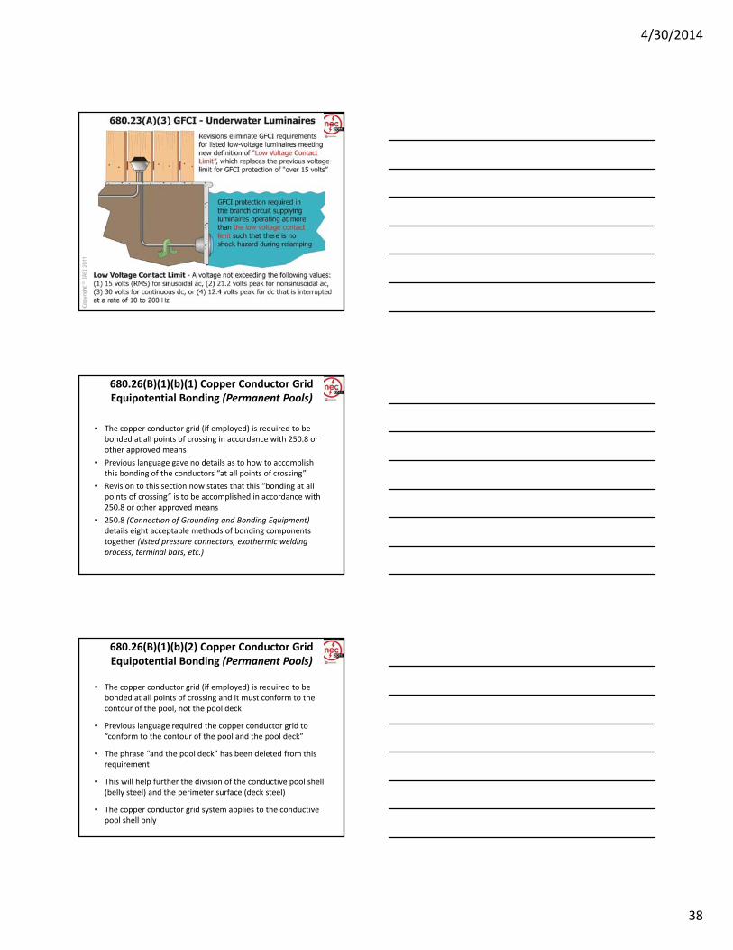
680.26(B)(1)(b)(1) Copper Conductor GridEquipotential Bonding (Permanent Pools)
• The copper conductor grid (if employed) is required to be bonded at all points of crossing in accordance with 250.8 or other approved means
• Previous language gave no details as to how to accomplish this bonding of the conductors “at all points of crossing”this bonding of the conductors at all points of crossing
• Revision to this section now states that this “bonding at all points of crossing” is to be accomplished in accordance with 250.8 or other approved means
• 250.8 (Connection of Grounding and Bonding Equipment)details eight acceptable methods of bonding components together (listed pressure connectors, exothermic welding process, terminal bars, etc.)
680.26(B)(1)(b)(2) Copper Conductor GridEquipotential Bonding (Permanent Pools)
• The copper conductor grid (if employed) is required to be bonded at all points of crossing and it must conform to the contour of the pool, not the pool deck
• Previous language required the copper conductor grid to “conform to the contour of the pool and the pool deck”conform to the contour of the pool and the pool deck
• The phrase “and the pool deck” has been deleted from this requirement
• This will help further the division of the conductive pool shell (belly steel) and the perimeter surface (deck steel)
• The copper conductor grid system applies to the conductive pool shell only

4/30/2014
39
4/30/2014
40
4/30/2014
4/30/2014

4/30/2014
41
680.43, Ex. No. 2 Indoor Installations (Spas and Hot Tubs)
A spa or hot tub installed indoors shall comply with the provisions of Parts I and II of this article except as modified by this section and shall be connected by the wiring methods of Chapter 3.
Exception No. 1: Listed spa and hot tub packaged units rated 20 amperes or less shall be permitted to be cord‐and‐plug‐connected to facilitate the removal or disconnection of the unit for maintenance and repair.
Exception No. 2: The equipotential bonding requirements for perimeter surfaces in 680.26(B)(2) shall not apply to a listed self‐contained spa or hot tub installed above the finished floor.
• A new exception to 680.43 eliminates equipotential bonding requirements for listed self‐contained spa or hot tub installed indoors above the finished floor

4/30/2014
42
680.71 Protection
• Hydromassage bathtubs and their associated electrical components shall be on an individual branch circuit(s) and protected by a readily accessible ground‐fault circuit interrupter.
4/30/2014
• All 125‐volt, single‐phase receptacles not exceeding 30 amperes and located within 1.83 m (6 ft) measured horizontally of the inside walls of a hydromassage tub shall be protected by a ground‐fault circuit interrupter(s).
680.74 Bonding• A new last sentence clarifies the bonding requirements for hydromassage bathtubs.
• Bonding applies to all metal piping systems and all grounded metal parts in contact with the circulating water.
4/30/2014
g
• The 8 AWG or larger solid copper bonding jumper is required for equipotential bonding in the hydromassage bathtub area.
• The bonding jumper is not required to be extended to any remote panelboard, service equipment, or grounding electrode.

4/30/2014
43
4/30/2014Photo: IAEI Archives
4/30/2014

4/30/2014
44
4/30/2014

4/30/2014
45
690.4(E) Wiring and Connections(Solar Photovoltaic Systems)
(E) Wiring and Connections. The equipment and systems in 690.4(A) through (D) and all associated wiring and interconnections shall gbe installed only by qualified persons.
Informational Note: See Article 100 for the definition of qualified person.
• “Qualified persons” required to perform the described work on Photovoltaic (PV) systems
690.4(F) Circuit Routing(Solar Photovoltaic Systems)
• New requirements were added for visibility and roof marking requirements on certain PV circuits
• Firefighting community has expressed concern about the safety of ventilating roofs where PV circuits are present
• Routing PV circuits along the building structural members will lower probability that the structural members will be compromised by the firefighting process during a fire
• When PV module system circuits are integrated into the roof, PV associated circuits are to be clearly marked on the surface of the roof as a visual aid for firefighters and other maintenance personnel

4/30/2014
46
690.4(F) Circuit Routing(Solar Photovoltaic Systems)
• (F) Circuit Routing. Photovoltaic source and PV output conductors, in and out of conduit, and inside of a building or structure, shall be routed along building structural members such as beams, rafters, trusses, and columns where the location of thosetrusses, and columns where the location of those structural members can be determined by observation. Where circuits are imbedded in built‐up, laminate, or membrane roofing materials in roof areas not covered by PV modules and associated equipment, the location of circuits shall be clearly marked.
690.4(H) Multiple Inverters (Solar Photovoltaic Systems)
(H) Multiple Inverters. A PV system shall be permitted to have multiple utility‐interactive inverters installed in or on a single building or structure. Where the inverters are remotely located from each other, a directory in accordance with 705.10 shall be installed at each dc PV system disconnecting means, each ac disconnecting means and at g gthe main service disconnecting means showing the location of all ac and dc PV system disconnecting means in the building.
Exception: A directory shall not be required where all inverters and PV dc disconnecting means are grouped at the main service disconnecting means.
• New provisions for more than one utility‐interactive inverter on a building or structure have been added

4/30/2014
47
4/30/2014
690.10(E) Back‐Fed Circuit Breakers(Stand‐Alone PV Systems)
• New requirements were put in place to ensure that plug‐in‐type back‐fed circuit breakers used with stand‐alone solar photovoltaic systems (PV) are secured in place
• Previous language specified that listed plug‐in‐type circuit breakers back‐fed from utility‐interactive inverters were permitted to omit the additional fastener normally required by 408.36(D) (Panelboard Back‐Fed Devices)
• New provisions will now require plug‐in‐type back‐fed circuit breakers connected to a stand‐alone inverter output to be secured in accordance with 408.36(D)
• 408.36(D) requires plug‐in‐type back‐fed overcurrent protection devices to be secured in place by an “additional fastener” that requires other than a pull to release the device from the mounting means (bus bar)

4/30/2014
48
4/30/2014

4/30/2014
49
690.45(B) and FPN
• (B) Ground‐Fault Protection Not Provided.
• For other than dwelling units where ground‐fault protection is not provided in accordance with 690.5(A) through (C), each equipment grounding conductor shall
4/30/2014
g ( ) q p g ghave an ampacity of at least two (2) times the temperature and conduit fill corrected circuit conductor ampacity.
• Note: The short‐circuit current of photovoltaic modules and photovoltaic sources is slightly above the full‐load normal output rating.

4/30/2014
50
4/30/2014

4/30/2014
51

4/30/2014
52
4/30/2014

4/30/2014
53
700.9(B)(5) Wiring• A new item (5) has been added to Section 700.9(B).
• From the source to the loads or from the source distribution overcurrent protection to the loads, it is required to maintain separation unless modified by any of the provisions in items (1) – (5).
4/30/2014
• The revised text clarifies that it is permitted to supply any combination of emergency, legally required, or optional loads from a single feeder or from multiple feeders or from separate vertical sections of a switchboard that are supplied by either a common bus or individually.
4/30/2014
4/30/2014

4/30/2014
54
4/30/2014
4/30/2014
700.9(D)(1)(2) FPN
• A new fine print note that references UL Guide Information category (FHIT) has been added to 700.9(D)(1)(2).
4/30/2014
• FPN: UL guide information for electrical circuit protection systems (FHIT) contains information on proper installation requirements to maintain the fire rating.

4/30/2014
55
4/30/2014Photo: Tyco Thermal Controls
4/30/2014
700.10(D)(1) Feeder‐Circuit Wiring (Emergency System)
• Revision increases the fire rating time from 1 hour to 2 hours for emergency system wiring
• Safe and systematic operation of emergency electrical systems is critical for heavily populated buildings and for high‐rise occupanciesg g p
• Fire protection requirements for emergency system feeder circuits help maintain the reliability as well as the performance of the emergency electrical system
• Revision increases reliability and performance by providing more time to safely evacuate the building in an emergency

4/30/2014
56
4/30/2014

4/30/2014
57
4/30/2014

4/30/2014
58
Article 708 Critical Operations Power Systems (COPS)
• This new article is the result of work by the NEC TCC‐assigned Task Group on Emergency and Standby Power Systems for Homeland Security.
• The objectives were to identify current minimum requirements that do not adequately address the level of integrity and quality for power sources, power distribution,
4/30/2014
g y q y p , p ,and signaling systems required due to threats and/or acts of terrorism, manmade disasters and natural disasters.
• Article 708 Critical Operations Power Systems (COPS)Part I. GeneralPart II. Circuit Wiring and EquipmentPart III. Power Sources and ConnectionPart IV. Overcurrent ProtectionPart V. System Performance and Analysis
Scope and Applicability
• Critical operations power systems are those systems classed as critical by a municipal, state, federal, other governmental agency having jurisdiction or by facility engineering documentation establishing the necessity for such a system.
4/30/2014
• Vital infrastructure facilities that if destroyed or incapacitated would disrupt national security, the economy, public health or safety; and where enhanced electrical infrastructure for continuity of operation has been deemed necessary by governmental authority.
• See Annexes F and G for additional information.
4/30/2014Photo: IAEI Archives

4/30/2014
59

4/30/2014
60
4/30/2014
727.6 Construction FPN
• A new fine print note has been added to 727.6 referencing UL 1685‐2000 Standard for Safety for Vertical ‐Tray Fire‐Propagation and Smoke‐Release Test for Electrical and Optical‐Fiber Cables.
4/30/2014
• The new information provides users with an explanation of the required testing for physical damage, smoke release, and fire spread in order for Type ITC cables to be listed as resistant to the spread of fire.

4/30/2014
61
4/30/2014
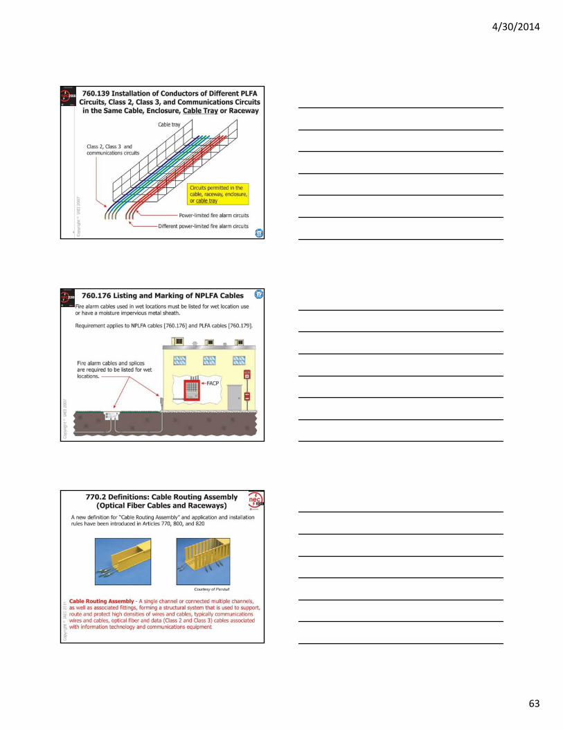
760.41(B) and 760.121(B) Branch Circuit
• Sections 760.21 and 760.41 have been renumbered as a result of the reorganization of Article 760.
• Branch circuits supplying PLFA and NPLFA systems
4/30/2014
• Branch circuits supplying PLFA and NPLFA systems shall not be supplied through ground‐fault circuit interrupters or arc‐fault circuit interrupters.
• The revisions to these sections result in a requirement that individual branch circuits be used to supply NPLFA and PLFA systems.
4/30/2014

4/30/2014
62
4/30/2014
4/30/2014
4/30/2014
63
4/30/2014
4/30/2014

4/30/2014
64
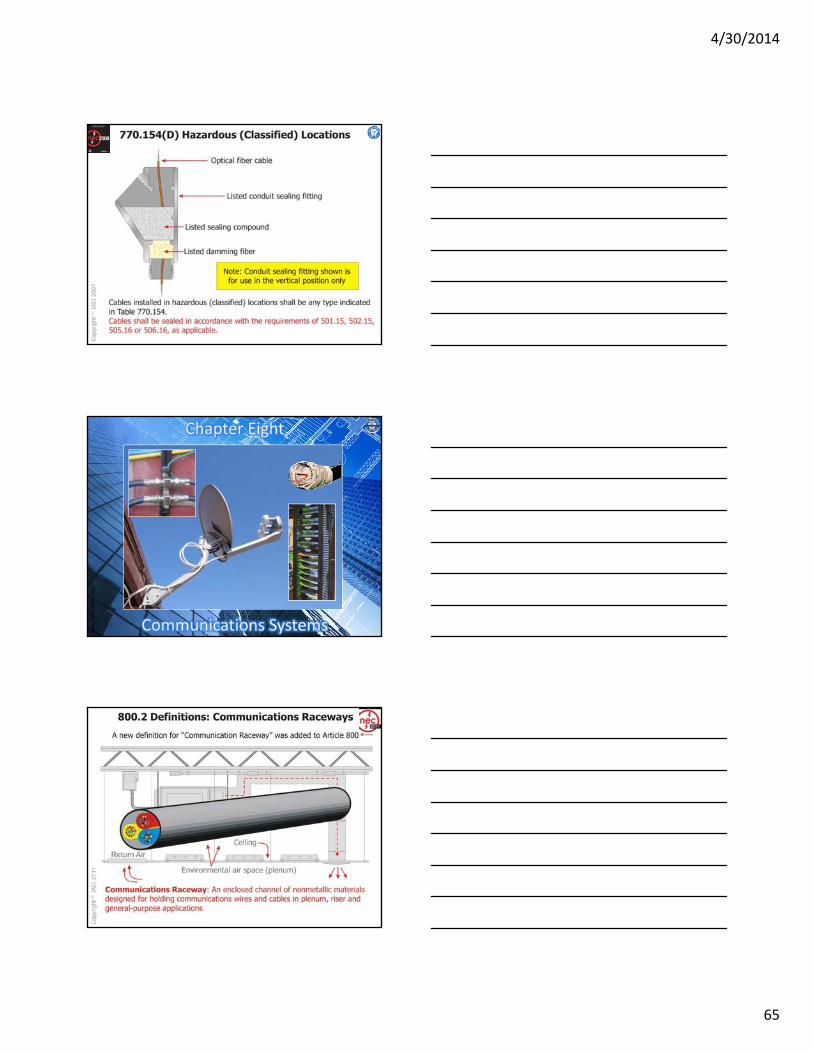
770.100 Bonding and Grounding (Optical Fiber Cables and Raceways)
770.100 Entrance Cable Bonding and Grounding (Optical Fiber Cables and Raceways) Where required, the non–current‐carrying metallic members of optical fiber cables entering buildings shall be bonded or grounded as specified in 770.100(A) through (D).
(B) Electrode. The bonding conductor and grounding electrodeconductor shall be connected in accordance with 770.100(B)(1), (B)(2), or (B)(3).
(1) In Buildings or Structures with an Intersystem Bonding Termination. If the building or structure served has an intersystem bonding termination as required by 250.94, the bonding conductor or grounding electrode conductor shall be connected to the intersystem bonding termination.
Informational Note: See Article 100 for the definition of Intersystem Bonding Termination.
4/30/2014
4/30/2014
65
4/30/2014

4/30/2014
66
800.24 Mechanical Execution of Work
• Listed and non‐listed securing methods and hardware are permitted to be used with network‐powered broadband communications circuits
4/30/2014
circuits.
• Cable ties are now recognized as a securing means for NPBCS cables.
4/30/2014Photo: IAEI Archives
800.100(A)(1), 820.100(A)(1), 830.100(A)(1)
• Physical Protection. The grounding conductor shall be protected where exposed to physical damage.
4/30/2014
• Where the grounding conductor is run in a metal raceway, both ends of the raceway shall be bonded to the grounding conductor or the same terminal or electrode to which the grounding conductor is connected.

4/30/2014
67
4/30/2014
4/30/2014

4/30/2014
68
4/30/2014
4/30/2014Photo: IAEI Archives
800.156 Dwelling Unit Communications Outlet
• At least one communications outlet is required to be installed within a dwelling unit.
• The wiring for this communication outlet shall be routed to the service provider demarcation point of the dwelling unit.
4/30/2014

4/30/2014
69
4/30/2014

4/30/2014
70
4/30/2014
4/30/2014Photo: IAEI Archives
4/30/2014

4/30/2014
71
4/30/2014

4/30/2014
72

4/30/2014
73
4/30/2014
4/30/2014

4/30/2014
74
4/30/2014