rhythm - squarespace · the rhythm is a 4 channel pattern generator with bpm display. it ships with...
TRANSCRIPT
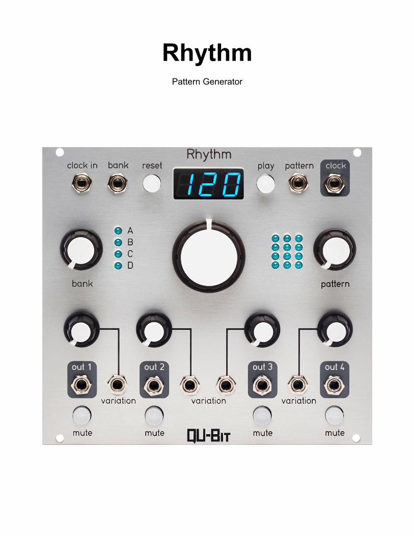
Rhythm
Pattern Generator
2
Description The Rhythm is a 4 channel pattern generator with BPM display. It ships with a multitude of genre-oriented rhythms that can be altered on a per channel basis. With each parameter under voltage control, an unlimited number of permutations are available. This unique interface removes the intricate patching necessary for crafting complex drum beats, and allows the user to focus on what matters most; composing and performing music.
- Infinite rhythmic variation
- Clock divider, random gates, and other utility modes accessible
- Intuitive performance interface
- BPM display
- Internal / External clocking capabilities with assignable PPQN settings
3
Table of Contents
Installation/Specifications 4 Rhythm 5 General Functions Overview 6 Setting Pulses Per Quarter Note 9 Setting Pulse Length 9 Rhythms and Explanations 10
4
Installation To install, locate 28 HP of space in your Eurorack case and confirm the positive 12 volts and negative 12 volts sides of the power distribution lines. Plug the connector into the power distribution board of your case, keeping in mind that the red band corresponds to negative 12 volts. In most systems the negative 12 volt supply line is at the bottom. The power cable should be connected to the Rhythm with the red band facing the bottom of the module. Specifications Format: 28 HP Eurorack module Depth: 23mm (Skiff friendly) Power Consumption: +12V = 186mA, -12V = 0mA

5
1 2 3 4 5 6
7
8
9
10
11
14
12
13
15
16

6
General Functions Overview 1. Clock Input: External Clock Input Inserting a clock signal to clock in will externally clock the Rhythm The number of pulses per quarter note for clock in can be set to 1, 4, 8, or 24 The default setting is 1 Pulse Per Quarter Note (PPQN) (See Setting Pulses Per Quarter Note (PPQN) for more information) 2. Bank Control Voltage Input: Unipolar positive control voltage input for bank Range: 0V – 5V
3. Reset Button: Button that, when pressed, will move the playback position to the beginning of the pattern
4. Play Button: Button that, when pressed, will either play or pause the recorded pattern based on the current state The tempo display will read PSE when the pattern is paused Note: When the play button is pressed, play/pause and mute states are written to non-volatile memory and will save in between power cycles
5. Pattern Control Voltage Input: Unipolar positive control voltage input for pattern Range: 0V – 5V
6. Clock Output: Tempo output The number of pulses per quarter note for clock out can be set to 1, 4, 8, or 24 The default setting is 1 Pulse Per Quarter Note (PPQN) (See Setting Pulses Per Quarter Note (PPQN) for more information)

7
7. Bank Knob: Determines the currently selected bank If the knob is far left, bank will be set to bank A If the knob is far right, bank will be set to bank D 8. Bank Indicator: Indication of the currently selected bank 9. Tempo Display: Indication of the currently selected tempo expressed in beats per minute 10. Tempo Knob: Sets the tempo of the internal clock If the knob is far left, the tempo will be as slow as possible If the knob is far right, the tempo will be as fast as possible 11. Pattern Indicator: Indication of the currently selected pattern 12. Pattern Knob: Determines the currently selected pattern within the currently selected bank If the knob is far left, pattern 1 will be selected If the knob is far right, pattern 12 will be selected 13. Variation Knob: Knob that, when turned from left to right, will add idiomatic embellishments to the corresponding trigger output based on the currently selected bank and pattern The last three knob settings will output 1/8 notes, 1/16 notes, and 1/32 notes respectively on every pattern (excluding the patterns in bank D) (See Rhythms and Explanations for more information on the bank D functionality)

8
14. Variation Control Voltage Input: Unipolar positive control voltage input for variation Range: 0V – 5V
15. Trigger Output Individual trigger output for channel 1 16. Mute Button Button that, when pressed, will stop the pattern from outputting on the corresponding channel Controls 13-16 are replicated on channels 2-4
9
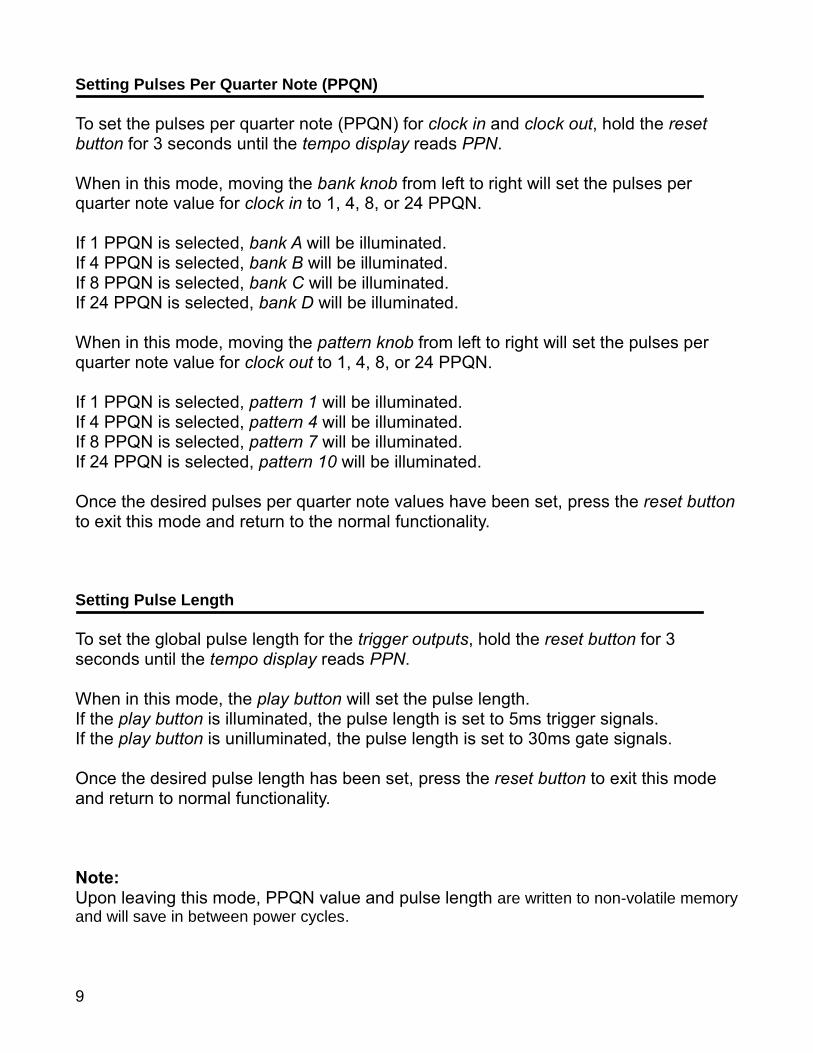
Setting Pulses Per Quarter Note (PPQN) To set the pulses per quarter note (PPQN) for clock in and clock out, hold the reset button for 3 seconds until the tempo display reads PPN. When in this mode, moving the bank knob from left to right will set the pulses per quarter note value for clock in to 1, 4, 8, or 24 PPQN. If 1 PPQN is selected, bank A will be illuminated. If 4 PPQN is selected, bank B will be illuminated. If 8 PPQN is selected, bank C will be illuminated. If 24 PPQN is selected, bank D will be illuminated. When in this mode, moving the pattern knob from left to right will set the pulses per quarter note value for clock out to 1, 4, 8, or 24 PPQN. If 1 PPQN is selected, pattern 1 will be illuminated. If 4 PPQN is selected, pattern 4 will be illuminated. If 8 PPQN is selected, pattern 7 will be illuminated. If 24 PPQN is selected, pattern 10 will be illuminated. Once the desired pulses per quarter note values have been set, press the reset button to exit this mode and return to the normal functionality. Setting Pulse Length To set the global pulse length for the trigger outputs, hold the reset button for 3 seconds until the tempo display reads PPN. When in this mode, the play button will set the pulse length. If the play button is illuminated, the pulse length is set to 5ms trigger signals. If the play button is unilluminated, the pulse length is set to 30ms gate signals. Once the desired pulse length has been set, press the reset button to exit this mode and return to normal functionality. Note: Upon leaving this mode, PPQN value and pulse length are written to non-volatile memory and will save in between power cycles.

10
Rhythms and Explanations Bank A:
1. House
2. Moombahton
3. Swing House
4. Pop 1
5. Funk
6. IDM 1
7. Amen Break
8. IDM 2
9. IDM 3
10. IDM 4
11. Breakdown
12. Pop 2
Bank B:
1. Hip Hop 1
2. R&B 1
3. Hip Hop 2
4. Hip Hop 3
5. Hip Hop 4
6. Hip Hop 5
7. Neo Soul
8. R&B 2
9. Break
10. 6/8 Groove
11. Triplet Groove
11
12. Hip Hop 6
Bank C:
1. African 1: Liberte
2. African 2: Baga Gine
3. African 3: Kassa Ni Soro
4. Latin 1: Salsa
5. Latin 2: Bossa Nova
6. Latin 3: Rhumba Clave
7. Bulgarian 1: Paidushko Horo
8. Bulgarian 2: Lesnoto
9. Bulgarian 3: Gankino Horo
10. Indian 1
11. Indian 2
12. Reggae
Bank D:
1. Ascending Sequential Gates:
Moving the variation knobs from left to right will output 1/4 notes, 1/8 notes, 1/8 note
triplets, 1/16 notes, and 1/32 notes respectively on every channel.
2. Descending Sequential Gates:
Moving the variation knobs from left to right will output 1/4 notes, 1/8 notes, 1/8 note
triplets,1/16 notes, and 1/32 notes respectively on every channel.
3. Pendulum Sequential Gates:
Moving the variation knobs from left to right will output 1/4 notes, 1/8 notes, 1/8 note
triplets,1/16 notes, and 1/32 notes respectively on every channel.
12
4. Chord Comping:
This mode has the same behavior as all patterns of the other 3 banks.
5. Binary Counter:
Moving the variation knobs from left to right will output 1/4 notes, 1/8 notes, 1/8 note
triplets, 1/16 notes, and 1/32 notes respectively on every channel
6. Clock Divider / Multiplier:
If the knob is center, the clock signal will be unaffected and will output 1/4 notes.
If the knob is far left, the clock signal will be divided by 32
If the knob is far right, the clock signal will be multiplied by 16
Division / Multiplication Range:
/32, /16, /8, /6, /4, /3, /2, =, *2, *3, *4, *6, *8, *16
7. Blues:
This mode has the same behavior as all patterns of the other 3 banks.
8. Jazz:
This mode has the same behavior as all patterns of the other 3 banks.
9. 5/4:
This mode has the same behavior as all patterns of the other 3 banks.
10. Random Gates:
Moving the variation knobs from left to right will increase the probability of the random
gates on every channel respectively.
13
11. Musically Derived Random Gates:
Moving the variation knobs from left to right will increase the range of possible note
values of the musically derived random gates.
If the knob is far left, 1/2 notes and 1/4 notes will be accessible.
If the knob is far right, 1/2 notes, 1/4 notes, 1/8 notes, 1/8 note triplets, 1/16 notes,
1/16 note triplets, 1/32 notes, and 1/64 notes will be accessible.
12. Random Individual Gates:
Moving the variation knobs from left to right will add 1/8 note, 1/8 note triplet, 1/16
note, and 1/32 note ratcheting to the random gates.