mpx r1… · (press two or more times in rhythm to establish ... the mpx r1 will flash at 100 bpm,...
TRANSCRIPT

User GuideMIDI Remote Controller
MPX R1
Lexicon Inc. • 3 Oak Park • Bedford MA 01730-1441 USA • Tel: 781-280-0300 • Fax 781-280-0490 • www.lexicon.com
Lexicon Part # 070-12712
Copyright 1997 Lexicon Inc., All Rights Reserved.
NoticeThis equipment generates and uses radio frequency energy and if not installed and used properly, that is, in strict accordance with themanufacturer's instructions, may cause interference to radio and television reception. It has been type tested and found to comply with thelimits for a Class B computing device in accordance with the specifications in Subpart J of Part 15 of FCC Rules, which are designated to providereasonable protection against such interference in a residential installation. However, there is no guarantee that interference will not occurin a particular installation. If this equipment does cause interference to radio or television reception, which can be determined by turning theequipment OFF and ON, the user is encouraged to try to correct the interference by one or more of the following measures:
Reorient the receiving antennaRelocate the computer with respect to the receiverMove the computer away from the receiverPlug the computer into a different outlet so that the computer and receiver are on different branch circuits.
If necessary, the user should consult the dealer or an experienced radio/television technician for additional suggestions. The user may findthe following booklet prepared by the Federal Communications Commission helpful:
"How to identify and Resolve Radio/TV Interference Problems."
This booklet is available from the U.S. Government Printing Office, Washington, DC 20402, Stock No. 004-000-00345-4.
Le présent appareil numérique n'émet pas de bruits radioélectriques dépassant les limites applicables aux appareils numériques de la classB prescrites dans le Règlement sur le brouillage radioélectrique édicté par le ministère des Communications du Canada.
Unpacking and InspectionAfter unpacking the MPX R1, save all packing materials in case you ever need to ship the unit. Thoroughly inspectthe unit and packing materials for signs of damage. Report any shipment damage to the carrier at once; reportequipment malfunction to your dealer.

Contents
1 Product OverviewIntroduction ......................................................................................... 1-1The Front Panel .................................................................................. 1-2The Rear Panel .................................................................................. 1-3Installation Notes ................................................................................ 1-4
Power Requirements .....................................................................1-4Connecting the MPX R1 to an MPX 1 ...........................................1-4Stand-alone Configuration ............................................................1-4
2 The MPX R1 as a Dedicated MPX 1 ControllerMPX 1 Software Requirements ...........................................................2-1MPX 1 and MPX R1 Connections ...................................................... 2-1Working in Program Mode .................................................................. 2-1
A/B, Tap/Tempo, Bypass, Toe and Pedal .................................... 2-1Loading Programs ........................................................................ 2-2
Direct Access Mode ............................................................... 2-2FX Mode ..............................................................................................2-3Relay State Programming .................................................................. 2-3Changing Programs vs. Bypassing Effects in a Guitar Rig .................2-4Using the MPX 1 and the MPX R1 in a Guitar Amp Effects Loop .......2-4Using the MPX 1 and the MPX R1 in a Preamp/Power Amp Rig or
a Dry/Wet (3-way) Rig .................................................................. 2-5Using a Series Loop ........................................................................... 2-5Using a Parallel Loop ......................................................................... 2-6
3 Using the MPX R1 with Other MIDI DevicesConnections ........................................................................................ 3-1Working in Program Mode .................................................................. 3-1
A/B, Tap/Tempo, Bypass, and Toe Switch ...................................3-1Loading Programs ........................................................................ 3-1
Direct Access Mode ............................................................... 3-2FX Mode ..............................................................................................3-2Relay State Programming .................................................................. 3-3
4 EditingEdit Mode Program Parameters ......................................................... 4-2Edit Mode FX Parameters .................................................................. 4-5The Relays ......................................................................................... 4-6
Latching ........................................................................................ 4-6Momentary, normally open............................................................4-6Momentary, normally closed ........................................................ 4-6Relay State Programming .............................................................4-7Assigning the Relay with tip and ring ............................................4-7Removing Relay Settings for all programs ................................... 4-7

Contents, cont'd. 5 Advanced ApplicationsTransmitting Multiple Program Changes on Separate MIDI Channels 5-1
Setups .......................................................................................... 5-1Activating Setups and Direct Device Control ......................... 5-2Creating a Setup .................................................................... 5-1Setup Parameters .................................................................. 5-2Clearing a Setup .................................................................... 5-2
Direct Device Control .......................................................................... 5-3Alternative Connections ...................................................................... 5-4
2 MIDI Cables and an MSA Adapter ............................................ 5-45-pin Connection (1 Cable for two-way MIDI with power
from an adapter) .................................................................... 5-4
6 TroubleshootingLow Voltage ........................................................................................ 6-1Overheating ........................................................................................ 6-1Common MIDI Problems .................................................................... 6-1Adjusting Pedal Tension ..................................................................... 6-2Reinitialization .................................................................................... 6-3
Reinitialization of the MPX R1...................................................... 6-3Reinitialization of the MPX 1 and the MPX R1 ............................. 6-3
7 SpecificationsSpecifications ..................................................................................... 7-1MIDI Implementation .......................................................................... 7-2

1-1
Product Overview
1Product Overview
The MPX R1 MIDI Remote Controller performs as a dedicated MIDI controllerfor the Lexicon MPX 1, or as a stand-alone MIDI control unit. Either way you useit, you'll appreciate its rugged, road-worthy construction and straightforwardcontrol surface.
The MPX R1 has two basic operating modes: Program Mode and FX Mode.Program Mode is used for sending MIDI Program Change messages. FX Modeis used to send other MIDI data such as Controller messages, and for selectingthe unit's built-in 4-state relay. When used with the MPX 1, FX Mode functionslike a "virtual pedalboard". Individual effect blocks can be turned on and off, andthree-state LEDs (off, red and green) indicate whether the effect block isunavailable (not programmed as part of the preset), off or on.The front panel FXbutton toggles between Program and FX modes.
In this manual, the available functions for different applications are presentedseparately — so you can easily find the sections you need to get up and runningquickly.
This first section presents general information about the R1 controls, as well assome basic information on installation, connections and power requirements.
Chapter 2 concentrates solely on using the R1 with the MPX 1. Chapter 3discusses the operation of the R1 as a stand-alone MIDI controller. Editingfunctions are discussed in Chapter 4, followed by a section detailing advancedapplications.
Introduction

LexiconMPX R1 User Guide
1-2
The Front Panel
DisplayFS1, FS2 and FS3 LEDs light to indicate state ofexternal foot switches.
3-Digit Display indicates ID number of currentlyloaded program.
Tempo LED flashes in time with current tempo ratewhen Tap is active.
A/B LEDs light to indicate A/B function is active.
Bank/Parameter SelectButtons increment and decrement program banks(0-25), or select adjustable parameters for editing.Pressing and holding either button activates fastscrolling.
TapWhen Tempo LED is flashing, sets tempo.(Press two or more times in rhythm to establishtempo rate.)
A/BAssignable switch, whenused with the MPX 1, acti-vates a variable glide be-tween patched parameters.
Programmable PedalOperates as an assignable MIDIContinuous Controller. ToeSwitch allows patched effects tobe turned on and off.
BypassAssignable switchsends a MIDI Control-ler value BYPASSON=127; BYPASSOFF=0.
FXToggles between Program and FXModes. LED off indicates ProgramMode is active. LED on indicates FXMode is active.
Switches (0-9)Press to complete a Program Change message whichconsists of the current Bank number and the switchnumber (0-9). In FX mode, switches can be pro-grammed to transmit any MIDI Controller, Clock com-mands, Relay settings or MIDI Program Change.Switches 0-9 are used for entering Program Changeselections in Direct Access Mode.
1-3
Product Overview
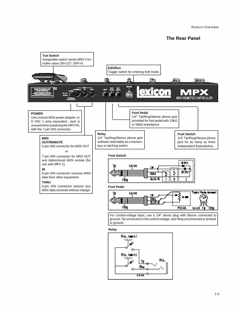
The Rear Panel
MIDIOUT/REMOTE5-pin DIN connector for MIDI OUT
or
7-pin DIN connector for MIDI OUTand bidirectional MIDI remote (foruse with MPX 1).
IN5-pin DIN connector receives MIDIdata from other equipment.
THRU5-pin DIN connector passes anyMIDI data received without change.
Foot Switch1/4" Tip/Ring/Sleeve phonejack for as many as threeindependent footswitches.
Toe SwitchAssignable switch sends MIDI Con-troller value ON=127; OFF=0.
Foot Pedal1/4" Tip/Ring/Sleeve phone jackprovided for foot pedal with 10kΩto 50kΩ impedance.
POWERUse Lexicon MSA power adapter, or9 VAC 1 amp equivalent. Jack isunused when powering the MPX R1with the 7-pin DIN connector.
For control-voltage input, use a 1/4" stereo plug with Sleeve connected toground, Tip connected to the control voltage, and Ring unconnected or shortedto ground..
Relay1/4" Tip/Ring/Sleeve phone jacksoftware selectable as a momen-tary or latching switch.
Edit/RunToggle switch for entering Edit mode.
Foot Switch
Foot Pedal
Relay
LexiconMPX R1 User Guide
1-4
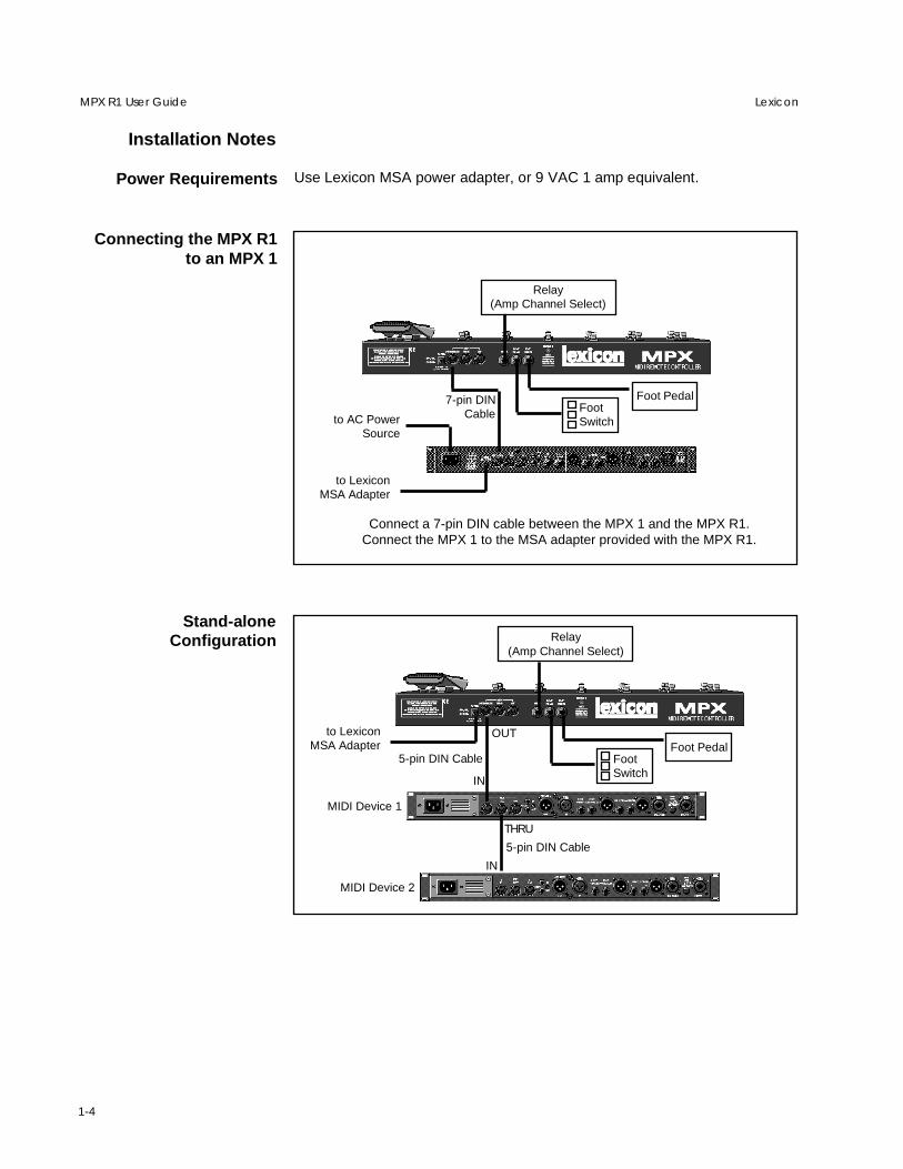
Installation Notes
Use Lexicon MSA power adapter, or 9 VAC 1 amp equivalent.Power Requirements
Connect a 7-pin DIN cable between the MPX 1 and the MPX R1.Connect the MPX 1 to the MSA adapter provided with the MPX R1.
Connecting the MPX R1to an MPX 1
Stand-aloneConfiguration
FootSwitch
Foot Pedal
5-pin DIN Cable
FootSwitch
Foot Pedal
Relay(Amp Channel Select)
to AC PowerSource
7-pin DINCable
Relay(Amp Channel Select)
to LexiconMSA Adapter
to LexiconMSA Adapter
IN
IN
THRU
5-pin DIN Cable
OUT
MIDI Device 1
MIDI Device 2

2-1
The MPX R1 as a Dedicated MPX 1 Controller
2The MPX R1 as aDedicated MPX 1Controller
When an MPX R1 is connected to an MPX 1, two-way communication isaccomplished via MIDI System Exclusive messages. This allows immediateresponse by both units to actions on either front panel.
Using the MPX R1 with the MPX 1 requires V1.10 software to be installed in theMPX 1. (The software version is shown on the MPX 1 display on power up.) Oncethis software is installed in your MPX 1, the following simple procedure will getyou up and running quickly. Note that these instructions assume a generalknowledge of MPX 1 operation. If you are a first-time MPX 1 user, please reviewthe MPX 1 User Guide for general instruction.
Connect the power adapter provided with the MPX R1 to the MPX 1 REMOTEPOWER input jack and to a wall outlet.
Power up the MPX 1 and connect the 7-pin DIN cable provided with the MPX R1between the MPX 1 rear panel IN/REMOTE jack and the MPX R1 MIDI OUT/REMOTE.
The MPX R1 will cycle through a power-up routine, lighting various LEDs, andthen display Con. The MPX 1 will display Remote Connected. These mes-sages indicate that proper bidirectional control has been established.
When the MPX 1 powers up, it will default to Program Mode. The MPX R1 shouldalso power up in Program Mode. (FX button LED should be off.) In this mode,the MPX R1 sends MIDI Program Change and Bank Select messages to loadMPX 1 programs.
These four switches and continuous controller transmit specific MIDI SystemExclusive or Control Change messages regardless of the mode of operation.
In this mode, the state of A/B and the Tempo LED rate will automatically updateto the state of the currently loaded program. For example, if you load a programset to 100 beats per minute (BPM), the MPX R1 will flash at 100 BPM, just asthe MPX 1 does. If you then load a program set to 120 BPM, the Tempo LED onthe MPX R1 will increase from 100 to 120 BPM when the new program loads.Pressing and holding the TAP button on the MPX R1 will display the currenttempo in BPM on the R1 display.
MPX1 and MPX R1Connections
MPX 1 SoftwareRequirements
Working inProgram Mode
A/B Tap/Tempo, Bypass,Toe and Pedal

LexiconMPX R1 User Guide
2-2
Loading Programs
Use the BANK buttons to select abank number. The first two digitson the display show your selection— bank 23 in this example.
Press one of the switches num-bered 0-9 to select a program withinthe selected bank. The third digitshows our selection — program 5.
Direct Access Mode You can also enter program numbers directly in Direct Access Mode. Press andhold the FX button until its LED begins blinking. The display will flash d-A toindicate that Direct Access Mode is active. Now you can select programs bydirectly entering their program numbers. For example, to load MPX 1 Program135, press 1, then 3, then 5 on the MPX R1.
In this mode, the BANK buttons increment and decrement the program numbersin consecutive steps.
Press the FX button once to exit to FX Mode, twice to exit to Program Mode.
The first two digits on the display indicate the bank number. The third digitindicates the program number. The BANK buttons select banks, and switches0-9 select programs within the displayed bank. Programs are loaded wheneverone of the numbered switches is pressed.
To load a new program within the same bank, press any of the numberedswitches (0-9).
To select a program in a different bank, press the BANK buttons to step to thebank you want, or hold down either button to scroll through the numbers. Therightmost digit, which is reserved for program numbers, will turn off during bankselection. Once you have selected the desired bank, press the numbered switchto load the program number within that bank.

2-3
The MPX R1 as a Dedicated MPX 1 Controller
FX Mode
Buttons 1, 2, 3, 6, 7 and 8 bring MPX 1 effects (Pitch, Chorus, Delay, Reverb,EQ and Mod) in and out of bypass. The LED for each button indicates the currentstate of the MPX 1 Effect:
Green = MPX 1 Effect onRed = MPX 1 Effect bypassed, but availableOff = MPX 1 Effect unavailable
As in Program mode, the R1 will update to match the current MPX 1 A/B, Tempoand Bypass states of the currently loaded program. If you press any of thesecontrols on the MPX 1, or if you load a new program from the MPX 1, the R1 willupdate accordingly.
You can also control the MPX R1 4-state relay in FX mode.
A relay is simply an electronic switch that can tell a circuit (typically an amp'schannel-switching scheme, or reverb and tremolo status) what "state" to go to.Manufacturers use different schemes, or "logic states" to accomplish similartasks, and the MPX R1 can be programmed to satisfy these requirements,allowing you, for example, to use your MPX R1 as a relacement for your amp'schannel-switching footswitch.
Storing a Relay StateThe relay state can be stored with each MIDI Program Change message. To dothis, select the desired MIDI program on the MPX R1 and press the MPX R1 FXbutton to enter FX mode
The relay states are assigned to the following buttons as factory defaults.
ON/OFF 1 = Relay state 1ON/OFF 2 = Relay state 2ON/OFF 3 = Relay state 3ON/OFF 4 = Relay state 4
FX Mode allows you to turn on and off any of the active effects in the currentprogram. To access FX Mode, press the MPX R1 FX button. The LED next tothe button will light to indicate you are in FX Mode.
The FX LED is lit when FX Modeis active.
Relay State Programming
LexiconMPX R1 User Guide
2-4
When you load a new program, it takes about 100 milliseconds for the MPX 1to fade out the old program and then fade in the new program. (That’s about a16th note at 120 BPM.) For most musical situations that’s plenty of time. Forthose situations where you really need to “nail” a sound change, you can bemore precise by using the individual effect bypass buttons (in FX Mode) toinstantly turn individual effects on or off.
For example, at the beginning of a tune, load a preset (using Program or DirectAccess Mode) with the effects you want — say, Chorus, Delay and Reverb.Then, while you're playing, turn the desired effects on and off from FX Mode viathe MPX R1 effect buttons.
First, connect the Effects Loop Send(s) to the MPX 1 Input(s).
If the Effects Loop send has two outputs (L, R):connect them to the left and right inputs of the MPX 1. On the MPX 1,press System, select Input Mode and set it to Stereo.
If the Effects Loop has only one output:connect it to the left input of the MPX 1. On the MPX 1, press System,select Audio: Input Mode and set it to Mono(L only).
Connect the MPX 1 Output(s) to the amp's Effects Loop Return(s)
If the Effects Loop has left and right return inputs:connect them to the left and right outputs of the MPX 1.
If the Effects loop has only a single return input:connect it to the left output of the MPX 1. (Effects will be richer if bothoutputs can be used, but MPX 1 V1.10 presets (100 through 159) havebeen optimized for use with only one output connected.
Changing Programsvs. Bypassing Effects
in a Guitar Rig
Using the MPX 1andthe MPX R1 in a Guitar
Amp Effects Loop
Press the button assigned to the desired relay state and hold the button downfor two seconds. The relay state (for example, CH1) will flash three times on theMPX R1 display to indicate that it has been stored with the program.
Clearing a Relay StateTo clear a relay state, press and hold any button not assigned to a relay channel.Hold this button down for two seconds until – – – flashes three times on thedisplay to indicate the relay state for that program has been removed.
Removing Relay Settings for All ProgramsTo reset all of the relay settings to Not Assigned, go to Edit: Program Mode(Press and hold the rear panel EDIT/RUN switch until Edt appears on thedisplay.) Use the BANK/Parameter Select buttons to select the Relay Initializeparameter (rEi). Press Yes/+ to reset all of the relays. Note that the relays stayin their last state (based on the last physical button press) until a button ispressed to assign a different state. Briefly press and release the rear panel EDIT/RUN switch to exit Edit Mode.

2-5
The MPX R1 as a Dedicated MPX 1 Controller
If you are using the MPX 1 between a guitar preamp and power amp, refer to thefollowing section on using a series effect loop.
If you are using the MPX 1 in a dry/wet (3-way) rig, refer to the following sectionon using a parallel effects loop.
What kind of effects loop doyou have?In a series effects loop, the entirepreamp signal passes through theMPX 1. (If you turn down the MPX 1Output Level control, no soundcomes out of the amplifier.)
In a parallel loop, the preamp signalis routed directly to the power ampand the MPX 1 output is mixed withit. (If you turn down the MPX 1 Out-put Level control, you still hear theguitar at normal level.)
Some amps have a mix control forthe loop. This is sometimes a switchlabeled “50/50” or “mix,”or a mix potwith a range of 0-100%. These con-trols allow you to use the loop aseither series or parallel. With aswitch, the 50/50, or mix, positioncorresponds to parallel, the otherposition corresponds to series. Inthe case of a mix pot, 100% corre-sponds to series and all other posi-tions are parallel. (Halfway or 50% isa good starting place.)
Using the MPX 1 andthe MPX R1 in aPreamp/Power AmpRig or a Dry/Wet(3-Way) Rig
Using a Series LoopOn the MPX 1:
Press System and make the following adjustments.
• Set Pgm Bypass to Bypass.
• Set Audio Bypass Level to –3dB.
(These settings will ensure that audio will be smooth and uninterrupted duringprogram changes.)
• Set Bypass Mode to Bypass. (You will hear dry guitar when bypass is on.)
• Set Mix Mode to Program so that each program will load with its ownindependent master wet/dry mix value. (The master mix value for eachpreset is initially set to work with the MPX 1 in a series effect loop.)
Adjust Mix and Level Values as follows:
• To adjust the overall mix of dry guitar to all effects in any program: press Mix,select Mstr Mix, and change the value to suite your taste.
• To adjust the mix or level or any of the effects in the program: press Mix,select the Mix or Level parameter for the desired effect block and adjust. Ifyou want to make the changes permanent, be sure to store your changesbefore loading a new program.
Set Input and Output Levels:
Before powering up the guitar amp, make your audio connections, turn theMPX 1 Output Level all the way down, and turn your guitar amp master volumeall the way down.
This can be a little tricky, since you must set the MPX 1 output level to match thelevel of the preamp with nothing connected in the loop. If the levels are too low,the amp will not have its usual power and tone. If the levels are too high, youmay overload the power amp – causing unwanted distortion. If your amp hasa loop bypass (like a Mesa/Boogie Mk IV), it’s pretty easy to match the levels.If not, it will take a little more work. The extra effort is worth it — when the levelsare properly matched, your amp’s tone will be unaffected and you will be ableto use phase shifter, tremolo, wah and other “in-line” effects to their fullestpotential.
• Power up the amp.
• Load MPX 1 Preset 100 Guitar Solo.
• Press Bypass.
• Set the preamp controls to the highest gain settings you’ll be using.
• Turn up the MPX 1 Input Level control so that the 0 dB lights occasionally,then back it off a bit.
LexiconMPX R1 User Guide
2-6
• Bring up the amp master volume to a point corresponding to a reasonablelistening level. (You won’t hear anything yet.)
• Turn the MPX 1 Output Level control a little more than halfway up (at about1:00 o’clock). You should now hear sound.
• Compare this level with the level when the MPX 1 is disconnected from theloop. (This is the tricky part — if your amp has a loop bypass, just bypass theloop. If it has a loop mix control, set the control to 0%. If not, you may haveto physically disconnect the MPX 1 from the loop.)
• Adjust the MPX 1 Output level control so that the amp's loudness is the sameas when the MPX 1 is not in the loop.
On the MPX 1:
Press System and make the following adjustments.
• Set Pgm Bypass to Mute.
• Set System Bypass Mode to Input Mute (delay and reverbs will “ring out”when Bypass is on) or All Mute (effects are muted when Bypass is on).
• Set Mix Mode to Global, press Mix and set Mstr Mix to 100%.
Adjust Mix and Level Values as follows:
• To adjust the overall mix of dry guitar to all effects in any program, press Mix,select Mstr Level, and change the value to suite your taste.
• To adjust the mix or level or any of the effects in the program: press Mix,select the Mix or Level parameter for the desired effect block and adjust. (Ifyou want to make the changes permanent, be sure to store your changesbefore loading a new program.)
Set Input and Output Levels:
Before powering up the guitar amp, make your audio connections, turn theMPX 1 Output Level all the way down, and turn your guitar amp master volumeall the way down.
[This is pretty simple, as you’re just adding the MPX 1 output to your normalguitar sound.]
• Power up the amp.
• Load MPX Preset 100, Guitar Solo.
• Set the preamp controls to the highest gain settings you’ll be using.
• Turn up the Input Level control so that the 0 dB lights occasionally whenyou're playing your loudest, then back it off a bit.
• Bring up the amp master volume to the desired listening level.
• Turn up the MPX 1 Output Level to the desired effects level.
Using a Parallel Loop

3-1
Using the MPX R1 with Other MIDI Devices
3Using the MPX R1with Other MIDIDevices
The MPX R1 can be used as a stand-alone controller for any standard MIDIdevice. When used this way, the MPX R1 transmits MIDI Program Change andControl Change messages, and controls the built-in 4-state relay.
Connect a 5-pin DIN MIDI cable between the MPX R1 rear panel OUT/REMOTEjack and MIDI IN jack of the device you wish to control. Connect the Lexicon MSAAdapter between the POWER jack on the MPX R1 and a wall outlet.
To control multiple devices, connect MIDI cables between the MIDI IN ports ofeach new device and the THRU ports of each preceding device.
When the MPX 1 powers up, it will default to Program Mode. The MPX R1 shouldalso power up in Program Mode. (FX button LED should be off.) In this mode,the MPX R1 sends MIDI Program Change and Bank Select messages to loadMPX 1 programs.
These four switches transmit information regardless of the mode of operation.They can be programmed to output an of the sources listed in Edit: FX Mode.
The first two digits on the display indicate the bank number. The third digitindicates the program number. The BANK buttons select banks, and switches0-9 select programs within the displayed bank. Programs are loaded wheneverone of the numbered switches is pressed.
To load a new program within the same bank, press any of the numberedswitches (0-9).
To select a program in a different bank, press the BANK buttons to step to thebank you want, or hold down either button to scroll through the numbers. Therightmost digit, which is reserved for program numbers, will turn off during bankselection. Once you have selected the bank you want, press the numberedswitch to load the desired program within that bank.
Connections
Working inProgram Mode
Loading Programs
Use the BANK buttons to select abank number. The first two digitson the display show your selection— bank 23 in this example.
Press one of the buttons numbered0-9 to select a program within theselected bank. The third digit showsour selection — program 5.
A/B, Tap/Tempo, Bypassand Toe Switch

LexiconMPX R1 User Guide
3-2
Direct Access Mode You can also enter program numbers directly in Direct Access Mode. Press andhold the FX button until its LED begins blinking. The display will flash d-A toindicate that Direct Access Mode is active. Now you can select programs bydirectly entering their program numbers. For example, to load MPX 1 Program135, press 1, then 3, then 5 on the R1.
In this mode, the BANK buttons increment and decrement the program numbersin consecutive steps.
Press the FX button once to exit to FX Mode, twice to exit to Program Mode.
FX Mode FX Mode allows you to use the MPX R1 buttons numbered 0-9 as MIDIControllers. To access FX Mode, press the MPX R1 FX button. The LED nextto the button will light to indicate you are in FX Mode.
The FX LED is lit when FX modeis active.
Buttons 0-9 can be assigned to any of the following MIDI controllers:
Continuous Controllers 1-31 Start/StopContinuous Controllers 33-119 StartA-B StopTip ContinueRing ResetCH1-4 Bypass
For additional information on all of these sources, refer to Chapter 4 Editing: FXParameters.
In FX Mode, transmitted values correspond to the state of the switch and areindicated by the switch LEDs as follows:
Green = 127 transmittedOff = 0 transmitted
Note that when used as a stand-alone controller, on and off are the only LEDindicators available. Note also that the LEDs for all of the buttons will remain intheir last toggled states.

3-3
Using the MPX R1 with Other MIDI Devices
You can also control the MPX R1 4-state relay in FX Mode.
Storing a Relay StateThe relay state can be stored with each MIDI Program Change message. To dothis, select the desired MIDI program on the MPX R1 and press the MPX R1 FXbutton to enter FX mode.
The relay states are assigned to the following buttons as factory defaults.
ON/OFF 1 = Relay state 1ON/OFF 2 = Relay state 2ON/OFF 3 = Relay state 3ON/OFF 4 = Relay state 4
Press the button assigned to the desired relay state and hold it down for twoseconds. The relay state (for example, CH1) will flash three times on the MPXR1 display to indicate that it has been stored with the program.
Clearing a Relay StateTo clear a relay state, press and hold any button not assigned to a relay channel.Hold this button down for two seconds until – – – is flashed three times on thedisplay to indicate the relay state for that program has been removed.
Removing Relay Settings for All ProgramsTo reset all of the relay settings to Not Assigned, go to Edit: Program Mode andselect the Relay Initialize parameter (rEi). Press Yes/+ to reset all of the relays.Note that the relays will stay in their last state (based on the last physical buttonpress) until a button is pressed to assign a different state.
Relay State Programming

LexiconMPX R1 User Guide
3-4

4-1
Editing
4EditingMPX R1 edit functions, like basic operations, are divided into two modes by the
front panel Program/FX switch. EDIT: Programs allows you to access systemparameters such as MIDI Channel, Relay state, MIDI Clock, etc. EDIT: FX allowsyou to re-assign the MIDI controllers transmitted by the MPX R1 front panelbuttons.
To access EDIT mode, press and hold the MPX R1 rear panel EDIT/RUN switch.(This recessed switch has been designed for easy access with a guitar pick, penpoint or fingernail.) After three seconds, the MPX R1 display will flash Edt twice,and the first Program mode parameter will appear as a default. The front panelA, B and Tempo LEDs will all light to indicate that the unit is in EDIT Mode. (Toexit, press and release the EDIT/RUN switch.)
DisplayIndicates ID and current value ofselected parameter.
Parameter SelectButtons step through availableparameters.
Yes/+ and No/–Adjust parameter value.
Press and hold the rearpanel EDIT/RUN switchto access the MPX R1Editing functions.
The A, B and Tempo LEDs will alllight to indicate you are in Editmode.
In either mode, the front panel BANK/Parameter Select buttons will step throughthe list of available parameters. The abbreviated name of each parameter willflash alternately on the display with the current parameter setting.
Parameter values are adjusted with the front panel YES/+ and NO/– buttons.Changes made to parameter values are immediate.
The following pages list all of the editable parameters in the MPX R1. An EditSummary showing this information in abbreviated form, is provided on anadhesive chart, to stick onto the bottom of the MPX R1 for easy reference.

LexiconMPX R1 User Guide
4-2
MIDI System Channel Assign Default: 1Assigns the MIDI transmit channel (1-16) for all buttons (except TOE).
MIDI Internal Pedal Channel Assign Default: 1Assigns the MIDI transmit channel (1-16) for the onboard foot pedal.
MIDI External Pedal Channel Assign Default: 1Assigns the MIDI transmit channel (1-16) for the external foot pedal/Analogcontroller.
MIDI Toe Channel Assign Default: 1Assigns the MIDI transmit channel (1-16) for the Toe switch.
External Foot Switch #1 State Select Default: 2Selects the foot switch state (Latching=1 or Momentary=2) for external footswitch #1. This allows a momentary foot switch to act like a latching foot switch.For momentary foot switches, leave this at the default setting (2).
External Foot Switch #2 State Select Default: 2Selects the foot switch state (Latching=1 or Momentary=2) for external footswitch #2. This allows amomentary foot switch to act like a latching foot switch.For momentary foot switches, leave this at the default setting (2).
External Foot Switch #3 State Select Default: 2Selects the foot switch state (Latching=1 or Momentary=2) for external footswitch #3. This allows a momentary foot switch to act like a latching foot switch.For momentary foot switches, leave this at the default setting (2).
MIDI Clock Output On/Off Default: OffSpecifies the source of MIDI clock output. Settings include: Off, On (generateinternally), re (merge from remote in), in (merge from MIDI in).
Program Load mode Default: 3Determines how program numbers are entered. Two states (indicated below bya /, indicates a second mode is available by pressing and holding down the FXbutton.(In the second mode, the FX light blinks.)
1 = Banks2 = Direct Access Mode3 = Banks/Direct Access4 = Banks/Direct Device5 = Setup/Direct Access6 = Setup/Direct Device
Redundant Program Change On/Off Default: OnWhen set to On (the default), the remote will send a redundant program changemessage. (If you select the same program number (0-9) as the program that isloaded, the remote will send that program change.) When set to Off, the remotewill not send a new program change if the program corresponding to the numberselected is already loaded.
Edit ModeProgram Parameters
1
2
3
4
5
6
7
8
9
10

4-3
Editing
Program Number Format Select Default: 1Allows selection of one of two numbering systems: 0-127 (0) or 1-128 (1) forprogram numbering. This is a display change only — In MIDI terms, the remotewill always send 0-127 values.
Bank Limit Select Default: 25When the MPX R1 is not connected to an MPX 1 (which forces 25 banks), amaximum bank number can be selected here to limit the total number ofaccessible banks. The available range is 0-99.
Programs Per Bank Default: 100Specifies the number of programs in each bank (and thereby tells the MPX R1when to send a bank change message). The available range is 1-128.
Bank Change Default: 32Allows selection of the MIDI Controller number to be used as the transmittedBank Select message, 0, 32 or 032.
Pedal Curve Select Default: 1Allows selection of a pedal curve. The available settings are 1-3.
11
12
13
14
15
16
17
18
19
20
21
22
1 2 3
Pedal Range Limit Low Default: 0Sets the controller value (0-127) transmitted when the pedal is in its lowestposition.
Pedal Range Limit High Default: 127Sets the controller value (0-127) transmitted when the pedal is in its highestposition.
External Pedal Curve Select Default: 1Selects a pedal curve (1-3).
External Pedal Range Limit Low Default: 0Sets the controller value (0-127) transmitted when the pedal is in its lowestposition.
External Pedal Range Limit High Default: 127Sets the controller value (0-127) transmitted when the pedal is in its highestposition. The default setting is 127.
Pedal Update Mode Default: OnWhen set to On, the pedal will update the current pedal controller valueimmediately. When pedal update is set to Off, the pedal controller value will onlybe updated when the pedal is moved.
Internal Pedal Calibration Default: OffCalibrates the pedal when Yes/+ is selected. Moving the pedal through its entirerange of travel will re-calibrate the range of the pedal (i.e. 0 for minimum value,127 for maximum value).

LexiconMPX R1 User Guide
4-4
External Pedal Calibration Default: OffCalibrates the pedal when Yes/+ is selected. Moving the pedal through its entirerange of travel will re-calibrate the range of the pedal (i.e. 0 for minimum value,127 for maximum value).
MIDI IN Merge On/Off Default: OffWhen set to On, MIDI data received at the MIDI IN jack will be merged to the MIDIOUT jack.
MIDI THRU Routing Select Default: rEAllows data from MIDI IN (in) or MIDI remote (rE) to be passed to the THRU port.
Relay Mode Select Default: 1Allows you to choose how the relay operates. The choices are: 1=latching,2=momentary normally open, 3=normally closed.
Relay Initialize Default: –Initializes all of the stored relay states. Choices are Yes or No.
Tempo LED On/Off Default: OnAllows you to turn the Tempo LED On or Off. The LED is normally On.
Device ID Assign Mode Default: 0Sets a Device ID number (0-126) for the remote.
Target ID Assign Mode Default: 0Set a Target ID number (0-126) for the remote.
MIDI Dump All Default: –When Yes/+ is pressed, all global settings, system parameters, controllerassignments, relay states and setup information will be dumped via SysEx to theMIDI OUT port.
MIDI System Dump Default: –When Yes/+ is pressed, all system parameters will be dumped via SysEx to theMIDI OUT port.
MIDI Controllers Dump Default: –When Yes/+ is pressed, all Controller Assignments will be dumped via SysExto the MIDI OUT port.
24
25
26
27
28
29
30
31
32
33
23

4-5
Editing
Edit ModeFX Parameters
Note: When the relay state is assigned to a selected button the relay willautomatically change to reflect the current state of the button. Relays with dualstates will default to the first state.
Note: In this mode, pressing any button will transmit the currently assignedcontroller. On exiting this mode, all switches will revert to the state they were inbefore Edit Mode was entered.
Each of the following buttons can be assigned to the following MIDI controllers:1-31, 33-119, Start/Stop, Start, Stop, Continue, Reset, tip, ring, CH1, CH2, CH3,CH4, Off, Bypass, MPX 1 SysEx message for A/B.
Bypass Default: CC84
1/Pitch Default: CC77
2/Chorus Default: CC78
3/Delay Default: CC76
4/On/Off 1 Default: CH1
5/On/Off 2 Default: CH2
6/Reverb Default: CC75
7/EQ Default: CC73
8/Mod Default: CC70
9/On/Off 3 Default: CH3
0/On/Off 4 Default: CH4
A/B 1 A/B SysEx
A/B 2 Off
Toe Default: CC83
Internal Pedal Default: CC4
External Pedal Default: CC11
External Footswitch 1 Default: CC80
External Footswitch 2 Default: CC81
External Footswitch 3 Default: CC82
Note that the A/B button can be assigned to simultaneously output two separatecontrollers. (It is designed to simultaneously toggle the A/B state of the MPX 1and the relay for amplifier switching.)
1
2
3
4
5
6
7
8
9
10
11
12
13
14
15
16
17
18
19
Pressing any switch as-signed to Bypass will dis-able all buttons, LEDs andcontrollers. While thisswitch is engaged, the LEDfor the button will light, andthe display will flash SuS(suspended).

LexiconMPX R1 User Guide
4-6
The Relays Two MPX R1 relays can operate in one of three modes: latching, momentarynormally open, and momentary normally closed. The Edit: Program parameterrel allows you to select one of these options.
The relays are activated by pressing a button assigned to the tip relay, the ringrelay, or to one of four channels. Any button can be assigned to turn the tip orthe ring relay on and off. You can also assign any one of the four channels to anybutton. The relay jack accepts a 1/4" TRS connector.
Latching
Momentary,normally open
Momentary, normally closed
Tip/RingPressing the button assigned to Tip causes the tip relay to change state.Pressing the button assigned to Ring causes the ring relay to change state.
ChannelsPressing a button assigned to a channel causes the channel to change. The fourchannels are defined as shown below:
Channel Tip Relay Ring Relay1 open open2 closed open3 open closed4 closed closed
Tip/RingThe tip and ring relays are defined as being normally open. Pressing the buttonassigned to the tip or the ring relay closes the relay for 100ms and then opensit again.
ChannelsThe “momentary, normally open” state of a channel is Channel 1. Pressing achannel button causes the relay to momentarily change to that channel’s stateand then change back to Channel 1. (Pressing a button assigned to Channel 1does nothing.)
Tip/RingThe tip and ring relays are defined as being normally closed. Pressing the buttonassigned to the tip or the ring relay opens the relay for 100ms and then closesit again.
Relay TipTo find out what relay statescheme your amp uses, con-nect a 1/4" TRS cable be-tween the MPX R1 and theamp's rear panel jack foramp switching. Experimentbe pressing the four MPX R1relay state switches to deter-mine how the default set-tings of the MPX R1 affectyour amp's channel-switch-ing scheme. Write down theresults before editing customstates and setups.

4-7
Editing
ChannelsThe “momentary, normally closed” state of a channel is Channel 4. Pressing achannel button causes the relay to momentarily change to that channel’s stateand then change back to Channel 4. (Pressing a button assigned to Channel 4does nothing.)
Storing a Relay StateThe relay state can be stored with each MIDI Program Change message. To dothis, select the desired MIDI program on the MPX R1.
Press the MPX R1 FX button to enter FX mode.
In the MPX R1 the relay states are assigned to the following buttons as factorydefaults.
ON/OFF 1 = Relay state 1ON/OFF 2 = Relay state 2ON/OFF 3 = Relay state 3ON/OFF 4 = Relay state 4
Press the button assigned to the desired relay state and hold the button downfor two seconds. The relay state (for example, CH1) will flash on the MPX R1display to indicate that it has been stored with the program.
Clearing a Relay StateTo clear a relay state, press and hold any button not assigned to a relay channel.Hold this button down for two seconds until – – – is flashed on the display toindicate the relay state for that program has been removed.
LatchingTo assign the relay using tip or ring when the relays are set to latching mode:
Assign the relay state to the desired button. This button will now have two relaystates: State 1 (Green) and State 2 (Off).
Follow the same method for assigning the relay as above. To save the CH1 relaystate, the button must first be put in CH2 relay. Then, when you press and holdthis button it will toggle the to the CH1 relay state.
MomentaryIf the relays are set to momentary, normally closed, or to momentary, normallyopen, you can store a momentary change on either the tip or the ring relay.
To reset all of the relay settings to Not Assigned, go to Edit: Program mode andselect the Relay Initialize parameter (rEi). Press Yes to reset all of the relays.Note that the relays will stay in their last state (based on the last physical buttonpress) until a button is pressed to assign a different state.
Relay State Programming
Assigning the Relay withtip and ring
Removing Relay Settingsfor all programs

5-1
Advanced Applications
5AdvancedApplications
The MPX R1 is capable of simultaneously outputting multiple MIDI ProgramChange messages (called Setups) on as many as eight different MIDI channels.It can access any MIDI channel and transmit Program Change messages in realtime. Each of these applications is described in this section.
A Setup consists of as many as eight MIDI Program Change messages and onerelay state. The MPX R1 can be programmed with as many as 100 Setups.
To activate Setups or Direct Device Control from Program mode you must select4, 5 or 6 as a setting for the PL (Program Load) parameter in Edit mode. Thisparameter allows you to select one of the following six options as a master modefor program load behavior:
1 Banks2 Direct Access3 Banks/Direct Access4 Banks/Direct Device5 Setups/Direct Access6 Setups/Direct Device
4 Banks/Direct Device uses the standard bank loading scheme on a singleMIDI channel selected in Edit Program Mode. Pressing and holding the FXbutton (from either Program or FX Mode) until the LED blinks and d-d flasheson the MPX R1 display activates Direct Device Control. Pressing FX againreverts to the standard bank loading scheme.
5 Setups/Direct Access activates Setup Mode. In this mode, all MIDI ProgramChanges are transmitted within Setups. Pressing and holding the FX buttontakes you into a version of Direct Access Mode which gives you direct accessonly to Setup load. Pressing FX again reverts to Setup Mode.
6 Setups/Direct Device activates Setup Mode. In this mode, all MIDI ProgramChanges are transmitted within Setups. Pressing and holding the FX button(from either Program or FX Mode) until the LED blinks and d-d flashes on theR1 display activates Direct Device Mode. Pressing FX again reverts to SetupMode.
To build a Setup, first set the rear panel EDIT/RUN switch to Edit Mode, thenpress and hold the FX button for approximately 2 seconds, until the FX LEDblinks.
The 1/PITCH LED should light up in red and the display should show SEt toindicate you are in Setup programming mode.
Transmitting MultipleProgram Changeson Separate MIDIChannels
Setups
Activating Setups and DirectDevice Control
Creating a Setup

LexiconMPX R1 User Guide
5-2
The front panel Yes/+ and No/- buttons allow you to select a Setup number (1-100) for programming. This number is assigned to the 1/PITCH button.
Each of the MPX R1 front panel buttons numbered 2-9 is now available tomemorize Program Change messages. (Button 0/ON/OFF 4 is available forstoring a relay state.)
Select the button you want (2-9) to designate a particular MIDI device.MPX R1 Button2/CHORUS Device 13/DELAY Device 24/ON/OFF 1 Device 35/ON/OFF 2 Device 46/REVERB Device 57/EQ Device 68/MOD Device 79/ON/OFF 3 Device 8
The BANK buttons will now select one of four parameters available to define theProgram Change messages you want to send. The Yes/+ and No/- buttons setthe value for each parameter you select.
PC (Program Change) lets you select a MIDI Program Change message (0-999)for the selected device. This parameter is specific to each Setup.
Ch (MIDI Channel) lets you select a MIDI Channel (1-16) for communication withthe selected device. This channel will be used for any devices assigned to thisbutton. This parameter is global for each device.
PPb (Programs Per Bank) lets you specify the number of programs in each bank(0-999), and therefore, when a bank change message will be transmitted. Thisparameter is global for each device.
bC (Bank Change Message) lets you define the Bank Select message (0, 32 or032) to be transmitted to the selected device. This parameter is global for eachdevice.
Once these parameters have been set, you can test the device by pressing 2/CHORUS. This will output all of the MIDI information you have programmed forthe selected device.
To select a relay state to store with the Setup, press 0/ON/OFF 4. This buttonis reserved for Setup relay state assignments. When you press the button, thedisplay should show rEL. on the display)
The Yes/+ and No/- buttons allow you to select the relay state you want storedwith the Setup.
To clear a Setup, go to Setup Edit mode, and select the number of the Setup youwant to clear, and hold down the BYPASS button. All of the front panel LEDsexcept 1/PITCH will turn off, indicating that the Setup has been cleared.
Clearing a Setup
Setup Parameters

5-3
Advanced Applications
Example
1. Press the button for the desired device. The LED will blink green. The firstparameter (Program Change) will be indicated by PC on the display.
2. Use the Yes/+ and No/– buttons to select a Program Change number.
3. Use the BANK buttons to select the next parameter, MIDI Channel.
4. Use the Yes/+ and No/– buttons to select a MIDI Channel.
5. Use the BANK buttons to select the next parameter, Programs Per Bank.
6. Use the Yes/+ and No/– buttons to select the appropriate number for theconnected device.
7. Use the BANK buttons to select the next parameter, Bank Change.
8. Use the Yes/+ and No/– buttons to select the appropriate setting for theconnected device.
Once all of the parameters have been set and you want to test this specific deviceProgram Change message, press the button you have selected to designate thedevice.
Once you press any other device button, this LED will light steady green toindicate that information is stored at this location.
Direct Device Control Mode is similar to Direct Access, except that the Bankbuttons change the MIDI Channel for Program Changes in real time.
In either Program or FX Mode, press and hold the FX button until the FX LEDblinks and d-d is flashed on the display. The display will then alternate thedisplay of the current MIDI Channel and the last Program Change numbertransmitted on that channel.
In this mode you can select programs directly by entering their numbers asbutton pushes (as in Direct Access). In addition, the Bank buttons let you accessMIDI Channels 1-16 so that you can transmit a Program Change on any MIDIChannel in real time.
When you press the FX button again you will revert to the Program Load modespecified by the PL parameter in Edit Mode with the MIDI Channel reset to thechannel specified by the Ch parameter, or to that specified for the Setup.
Direct DeviceControl

LexiconMPX R1 User Guide
5-4
AlternativeConnections
2 MIDI cablesand an MSA Adapter
5- pin connection(1 cable for two-way
MIDI with power froman adapter)
The following methods allow you to establish two-way MIDI communicationbetween an MPX R1 and an MPX 1 without using a 7-pin MIDI cable.
Connect a 5-pin MIDI cable between the MPX R1 rear panel OUT/REMOTE jackand the MPX 1 rear panel MIDI IN/REMOTE jack.
Connect a second 5-pin MIDI cable between the MPX 1 rear panel MIDI OUTjack and the MPX R1 rear panel MIDI IN jack.
Connect the MSA Adapter to the MPX 1 rear panel POWER jack and plug intoa wall outlet.
If you have a 5-pin MIDI cable which has all five pins wired, connect it betweenthe MPX R1 rear panel OUT/REMOTE jack and the MPX 1 rear panel MIDI IN/REMOTE jack.
Connect the MSA Adapter to the MPX 1 rear panel POWER jack and plug intoa wall outlet.

Troubleshooting
6-1
6Troubleshooting
This chapter is intended primarily to help you recognize some common errorstates which can be corrected from the MPX R1 front panel, or by simple meanssuch as cable replacement. Any error states that are not covered here should bereferred to your local dealer or Lexicon Customer Service.
In “low-voltage”, or “brown-out” conditions (less than 40VAC), the MPX R1 willfreeze in its current state. None of the controls will have any effect. When powerreturns to a normal level, the unit will reset itself as though it had just beenpowered on. If the unit does not reset itself, turn the power OFF, then ON toresume normal operation.
Temperature extremes may cause the MPX R1 to exhibit unpredictable behav-ior. If the unit has been subjected to temperatures below 32°F (0°C) or above95°F (35°C), it should be turned off and allowed to return to normal temperaturebefore use. The unit may be damaged by exposure to temperatures below -22°F(-30°C) or above 167°F (75°C), or by exposure to humidity in excess of 95%. Ifa unit exposed to such conditions fails to operate after it returns to a normaloperating temperature, contact your local service representative.
The MPX R1 doesn't respond to MIDI Program Changes.The MPX R1 and connected devices must be set to matching MIDI Channels.Check the connected device (if an MPX 1, check in the System mode MIDImenu) as well as in the MPX R1 Edit mode to verify MIDI channel selections.
If connected to an MPX 1:Make sure that Pgm Change in the MPX 1 System mode MIDI menu is set toOn. See MPX 1 User Guide Chapter 6: MIDI Operation for Program Changemessages which may be ignored by the MPX 1.
Check MIDI connections between the units.
Low Voltage
Overheating
Common MIDIProblems
6-2
LexiconMPX R1 User Guide
Reinitialization
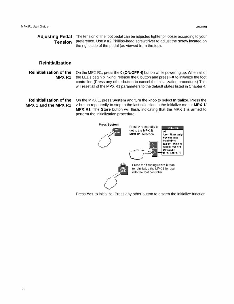
Press System.Press > repeatedly toget to the MPX 1/MPX R1 selection.
Press the flashing Store buttonto reinitialize the MPX 1 for usewith the foot controller.
On the MPX R1, press the 0 (ON/OFF 4) button while powering up. When all ofthe LEDs begin blinking, release the 0 button and press FX to initialize the footcontroller. (Press any other button to cancel the initialization procedure.) Thiswill reset all of the MPX R1 parameters to the default states listed in Chapter 4.
On the MPX 1, press System and turn the knob to select Initialize. Press the> button repeatedly to step to the last selection in the Initialize menu: MPX 1/MPX R1. The Store button will flash, indicating that the MPX 1 is armed toperform the initialization procedure.
Press Yes to initialize. Press any other button to disarm the initialize function.
Adjusting PedalTension
The tension of the foot pedal can be adjusted tighter or looser according to yourpreference. Use a #2 Phillips-head screwdriver to adjust the screw located onthe right side of the pedal (as viewed from the top).
Reinitialization of theMPX R1
Reinitialization of theMPX 1 and the MPX R1

Specifications
7-1
7Specifications
Dimensions: 23 in x 8 in x 3 in (WHD) (58.42 cm x 20.32 cm x 7.62 cm)
Weight: 9.5 lbs (4.3 kg)
Construction: All metal chassis, switches and expression pedal
External control inputs: 1 1/4" TRS jack supports up to 3 on/off switches1 1/4" TRS jack for external expression pedal
Internal relays: 1 1/4" TRS jack connected to two internal programmable relays
MIDI: MIDI OUT/REMOTE: 7-pin DIN connector (compatible with standard 5-pin MIDI)provides phantom power and two-way MIDI communication with the MPX 1
MIDI IN: standard MIDI IN can also be used to merge a second MIDI input streamwhen MIDI OUT/REMOTE is connected
MIDI THRU: can be set to pass MIDI from either MIDI IN or REMOTE ports
Power: 9VAC, 1A wall transformer provided
25-foot 7-pin DIN cable for phantom power via MPX 1
Expression pedal: vintage mechanical design, all steel construction, progammable toe switch
Display: 3-digit LED indicates program number and tempo rate
MIDI functions: MIDI bank and program select for up to 300 programs
Switches and pedal(s) can be individually set to transmit any controller. The statusof each MIDI switch is indicated with a green LED.
Tap tempo can be transmitted as MIDI Clock
Relay mapping: Different relay states can be memorized for each of 990 MIDI program numbers
Relays can operate as on/off 1–4 or as two independent on/off switches
MPX 1 functions*: When connected to an MPX 1 via 7-pin cable, R1 LEDs automatically display thefollowing each time a new program is loaded:
Program number
Master Bypass state
A/B state
Tempo rate
State of each effect block (Pitch, Chorus, EQ, Mod, Delay, Reverb); effecton=green, effect bypassed=red, effect not active=off)
The state of any active effect can be instantly changed by pressing its associatedswitch
Dedicated switches for control of A/B and Tap.
* MPX 1 requires V1.1 ROM upgrade

7-2
LexiconMPX R1 User Guide
MIDI Implementation Chart
Mode 1: OMNI ON, POLY Mode 2: OMNI ON, MONO O : Yes OX: SelectableMode 3: OMNI OFF, POLY Mode 4: OMNI OFF, MONO X : No
Lexicon MPX R1MIDI Remote Controller
Function Transmitted Recognized Remarks
Basic Default 1 XChannel Changed 1-16 X
Mode Default X XMessages X XAltered X
Note X X
Velocity Note ON X XNote OFF X X
After Keys X XTouch Channel X X
Pitch Bend X X
Control 1-119 OX X OFF, 1-119, Start/StopChange Start, Stop, Continue, Rest,BYPASS, PITCH, CHORUS, DELAY, Tip, Ring, CH1-4, Off,ON/OFF1-4, REVERB, EQ, MOD, BYP (0, 32, 032 selectFS 1-3, TOE SWITCH, INTERNAL Banks). All transmit ON=PEDAL 1-2 127; OFF=0
INTERNAL PEDAL 1 and 2are continuous controllers
Program 0-127 X Bank change allowsChange True # 1-128 access to programs 0-300
Bank Select O O
System Lexicon OX OX Limited set of SysExExclusive messages
System :Song Pos X XCommon :Song Sel X X
:Tune X X
System :Clock OX X Default set to OFF butReal Time :Commands OX X can be turned on. Default
tempo=120bpm
Aux :Local ON/OFF X XMessages :All Notes OFF X X
:Active Sense X X:Reset All Controllers OX X
Notes

Lexicon Part # 070-12712
Lexicon Inc.3 Oak ParkBedford MA 01730-1441 USATelephone 781-280-0300Fax 781-280-0490www.lexicon.com