rhode island transportation information system
TRANSCRIPT

PREPARED FOR
UNIVERSITY OF RHODE ISLAND
TRANSPORTATION CENTER
THE DESIGN AND DEVELOPMENT OF INFORMATION &
COMPUTER SYSTEMS FOR URITC
JOAN PECKHAM, LISA DIPIPPO, AND VICTOR FAY WOLFE
October 2001
URI-TC PROJECT NO. 536105
DISCLAIMER This report, prepared in cooperation with the University of Rhode Island Transportation Center, does not constitute a standard, specification, or regulation. The contents of this report reflect the views of the author(s) who is (are) responsible for the facts and the accuracy of the data presented herein. This document is disseminated under the sponsorship of the Department of Transportation, University Transportation Centers Program, in the interest of information exchange. The U.S. Government assumes no liability for the contents or use thereof.

2
Table of Contents
Abstract ii I. Overview of Project 2 II. Execution of Project 2 III. Results and Summary 3 Attachment, High Level System Design Appendix A – Overall System Layout Appendix B - Description of Participating Actors Hierarchical Users’ Structure Main Use Cases Major Participating Classes

3
The Design and Development of
Information &
COMPUTER SYSTEMS FOR URITC FINAL REPORT URITC #536105
Joan Peckham, Lisa DiPippo, Victor Fay
Wolfe
OCTOBER 2001
I. OVERVIEW OF THE PROJECT: The purpose of the project is to provide the design of an infrastructure that will support ongoing and future research projects and the daily functioning of the transportation center. This includes statistical analyses and evaluations of products, systems and techniques for the development, maintenance, and scheduling of the intermodal transportation systems. This infrastructure will have several features that will facilitate ease of use, rapid initial development, and well designed growth and maintenance as follows: ♦ Real-time - features will permit the rapid monitoring, reporting, and response to modal traffic
density, scheduling, and weather and accident conditions. ♦ Data warehousing and mining - These facilities will permit the storage of historical data for
later access and analysis. ♦ Extensible and maintainable - Advanced software design techniques will be employed to
assure that the system is extensible and maintainable. We will use a high-end software design tool, Rational Rose. Rose employees the industrial standard, UML for software analysis and design. While the initial purpose of the URITC system might be to monitor local traffic, accident, and weather patterns for the DOT (Department of Transportation), there might be a need to extend it to include other regions of the country, as well as to law enforcement agencies in this region. A good design ensures reusability and easy extension of the software and its design.
♦ Concurrency - One of the most important features of a database management system is to permit the concurrent access to data. This system will be designed and implemented from the beginning to support these features (even though many frequently employed file systems or lightweight database systems do not support this feature).
♦ Open and Free Software (whenever possible and practical) - Free software is software that is freely distributed and used by others. Open software is software that provides all or part of the source code to others so that they can freely modify for their own purposes. There are two strategies for this. First, all of the source code is available to the users (white box option).

4
Second, the modules of the system have well defined interfaces and thus are easily removed and replaced by other programmers.
♦ Web-based - The information system will be accessible from any location on the World Wide Web (WWW). This includes access to the transportation data and any free software that is developed by the students.
II. EXECUTION OF PROJECT The project underwent several phases that included supported graduate students and one software engineering design team. In the initial phase a group of undergraduate students was led by a graduate student in a CSC 305 Software Engineering class to interview Professor Hunter of Civil Engineering. These students developed a preliminary design and prototype implementation. In the second phase, supported graduate student, Angela Uvarova, interviewed Professor Hunter, and talked with Cynthia Levesque and the employees at RI TMC about future ITS needs. Angela then used the software design tool provided by Rational as match to provide a high-level software architecture for a next generation ITS system. III. RESULTS AND SUMMARY The results of this design are provided in the attachment. The important accomplishments are as follows: ♦ Multidisciplinary - Computer science professors and students begin to get an idea of the ITS
discipline, the state of the art, and the computer software needs of transportation researchers and professionals.
♦ Educational - One female student learns how to use a high-end software design tool and an open source database (Postgres). One software engineering class team begins the high-level software design on a "real" and multidisciplinary project.
♦ A blueprint is developed for a new generation and integrated ITS system. It serves as a basis for Year Two work with Professor Hunter in which we look in more detail at a slice of the integrated system with technical support for a web based travel time prototype using GIS and database technology.
♦ A preliminary design is developed and used in two funding proposals in an attempt to secure matching funds for continuation of this URITC ITS project.
This was a preliminary high level and practical design. No published works are expected from this. We expect it will take 3 years before we can identify publishable work and
complete it. This is due to the multidisciplinary nature of the project. It takes some time to educate all partners and then identify viable results. The issue of integrating standalone systems and providing seamless data archiving and access capabilities is a problem not unique to the transportation domain. We are interested in abstracting this to the more general computing problems and expect to derive engineering, computer science and
applied research results in the future.
We presented this work at the Thirteenth Rhode Island Transportation Forum on Friday, October 13th, 2000. We have submitted one paper to the Northeast Decision
Sciences Annual Meeting entitled “Moving Smart in Rhode Island” This is based upon the Year II work that we have now carried out as a continuation of this Year I
work. We thank the URI TC for their support in this project and for providing a venue for presentation of the preliminary results.

5

6
University of Rhode Island
Department of Computer Science and Statistic
Rhode Island
Transportation Information System.
(RITIS)
2000-2001

7
CONTENTS
DESCRIPTION OF SYSTEM ARCHITECTURE.................................................. 8
APPENDIX A: Overall System Layout ............................................................ 13
APPENDIX B: Description of Participating Actors ........................................ 15

8
Description of system architecture
The goal of this work was to provide a preliminary design for the Rhode Island
Transportation Information System (RITIS). On the current stage of this project (after 5
months) the following task requirements described in the proposal are met:
Requirements,
System Design,
Software system product review (back-end components),
Software selection and middle level system.
Requirements.
We have had a series of consultations and discussions with Cynthia Levesque,
TOC Manager, RI Dept. of Transportation and Dr. Chris Hunter, Dept. of Civil and
Environmental Engineering of URI. The results are presented as formal descriptions or
Use Cases (see Appendix B).
System design.
System will be implemented by using multi-tier model. The diagram presenting
tiers layout can be found in Appendix A.
The layers of the systems are the following:
• Sensors – the devices presenting environmental and traffic information to the
system (including video cameras);
• Sensors Interfaces – the software providing, delivering and storing sensor
information into the database;

9
• Persistent Storage – enterprise level DBMS providing storage (warehousing)
of the data;
• Business Logic – software providing system logic rules enforcement and data
delivery to the Presentation Layer;
• Presentation – software providing the end user interfaces.
The detailed description of the sensors and sensors interface layers is not the
responsibility of Transportation research team of Dept. of Computer Science but we
expect to get this information from the other parties of this project.
We will describe our choice of DMBS for persistent storage in the consecutive
sections as well as our choice of software technology for the business logic and
presentation layers.
Software system product review and software selection.
We reviewed software systems, products and technologies for the following
layers of the transportation system:
• Persistent Storage – platform + DBMS;
• Business Logic - platform + web server + dynamic web page content
technology;
• Presentation.
We chose PostgreSQL as a DBMS for the persistent storage layer. It satisfies the
following criteria:
• Open and free software (one of the project objectives);
• Scalability;

10
• Ease of administration;
• Performance;
• SQL compatibility;
• Programming support;
• Important features (replication ability, support triggers, support for stored
procedures, transactions, locking);
• Geographic Information System (GIS) compatibility.
The candidates consider were
• MySQL,
• PostgreSQL,
• mSQL.
They were compared with each other by the above criteria as well as with Oracle.
The PostgreSQL team just released a new version (7.x), which significantly
decreases a number of disadvantages of their DBMS and makes our choice even more
reasonable.
As a technology for Business Logic layer we considered the following:
• CGI;
• ASP (Jscript, VBScript - Microsotf);
• PHP;
• Java Servlets;
• Netscape Java server scripts.

11
We didn’t really think about CGI as real candidate for our system since all other
technologies were much newer and were dedicated to replace CGI because of the lack of
performance and other very important issues. We use it as a starting point for looking at
other technologies - what we were trying to do is to avoid known problems with CGI.
The only real candidates to be used in our system were PHP and Java servlets
(both: Java Server Pages and pure Servlets) since portability of the system is an important
issue and ASP with Java server scripts are technologies used only with certain products
of Microsoft and Netscape. They also are expensive products. PHP and Java servlets
allow us to use freely available software for multiple platforms.
Eventually we decided to use Java Server Pages (JSP, an extension of Java servlet
technology). We used the following criteria:
• Open free software;
• Performance;
• Ease of programming;
• Expandability;
• DBMS connectivity;
• Portability.
The task of choosing a platform or operating system was relatively easy. The only
(open source) candidate was Linux, although there was a difficulty of choosing particular
distribution (version) of Linux. Finally we decide to use the latest Red Hat Linux version.
We think that all user interfaces should be presented as web pages. It will provide
uniform way of presenting information for all platforms. There is a number of freely
12
available web-browsers for all popular platforms. Our system will guarantee
compatibility with Microsoft Internet Explorer 4.0 and later versions, Netscape Navigator
4.0 and later versions and some other browsers.
As a web server we decide to use Apache. It is free and open software providing
support for JSP technology and available for all popular platforms. It is also one of the
most popular pieces of server software.
All of the software described above defines basic hardware requirements (see
documentation for Red Hat Linux 6.2, PostgreSQL 7.1 and Apache). All mentioned
software packages and technologies can use a PC with a cheap common configuration. Of
course the better the processor power, memory and hard drive, capacity, access speed and
network bandwidth then the better the performance of the system will be. The acceptable
parameters should be defined during the testing phase of the project.
Besides software and hardware design our work includes a conceptual design of
essential portion of the system. For this purpose we used the Rational Rose 98i product.
This software is designed to provide the software developer with a complete set of visual
modeling tools for the development robust systems.
At this stage of the project we have actors, use cases, general classes and different
kinds of their interactions and relations among the modules of the system (see Appendix
B).

13
Appendix A: Overall System Layout

Overall System Layout
DBMS and
DATA WAREHOUSING
Regular Users/ Research Teams
Video Cameras
Interface Layer
Other Data
s
Interface Layer
Business Logic Layer
Presentation Layer
EmergencServices(Protected)
GIS
y
DeTr
Sensor
14
partment of ansportation (Protected)

15
Appendix B: Description of Participating Actors

16
Description of Participating Actors. Actor: Department of Transportation (DOT)
Description: Department of Transportation is a party of the information system that has
access to all the possible information in the system.
Actor: Regular User/Research Team Description: Regular user/Research team is a party of the information system that can
request the certain information in the system.
Actor: Emergency Service Description: Emergency Service is a party of the information system that can request
certain information in the system.
Actor: Sensor
Description: Sensor is a party of the informational system that provides weather/road
condition information to the system.
Actor: Police Department Description: Police Department is a party of the informational system that provides
traffic information to the system.
Actor: Dinamic Sign Board
Description: Dinamic Sign Board is a party of the information system that receives
information from the system on a regular base.
Actor: Primary/Secondary Data Mining Agent Description: Primary/Secondary Data Mining Agent is a party of information system that
computes primary/secondary reports based on raw data or intermediate reports and puts
them in the database.
17
Actor: Video Camera
Description: Video Camera is a party of the information system that provides traffic
information to the system.
Actor: E-Mail Robot Description: E-Mail Robot is a party of information system that sends information to
users on a regular base.

18
HIERARCHICHAL USERS’ STRUCTURE * Department of Transportation can be involved in any use cases defined for Regular User/Research Team and the Emergency Service actors.
Figure 1.
Regular User/ Research Team
Emergency Service
Department of Transportation
19
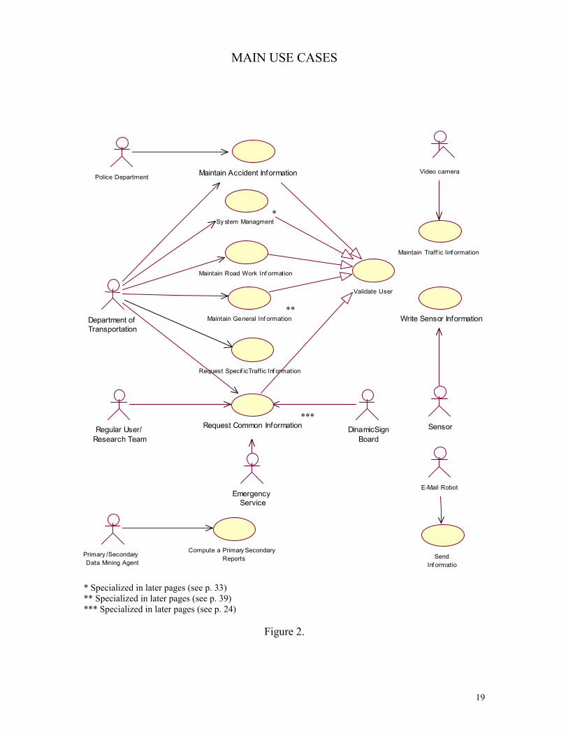
MAIN USE CASES
*
**
***
* Specialized in later pages (see p. 33) ** Specialized in later pages (see p. 39) *** Specialized in later pages (see p. 24)
Figure 2.
Police Department Maintain Accident Information Video camera
Maintain Traff ic Iinf ormation
Write Sensor Information
Sensor
E-Mail Robot
SendInf ormatio
DinamicSignBoard
Request Common InformationRegular User/Research Team
EmergencyService
Compute a Primary SecondaryReports
Primary /SecondaryData Mining Agent
Request Specif icTraffic Inf ormation
Maintain General Inf ormation
Maintain Road Work Inf ormation
Sy stem Managment
Validate User
Department ofTransportation

20
USE CASE Request Specific Traffic Information
Overview: The purpose of this use case is to provide a user with different traffic condition reports calculated in different intervals of time.
Actors: DOT
Starting Point: This use case begins when user chooses the appropriate option in the user menu.
Ending Point: This use case ends when user chooses another option in the user menu.
Measurable Results: Appropriate information appears in the screen.
Flow of Even 1. The system provides the user with the ability to choose the location of desired sensors
information. 2. The system provides actor with ability to choose the type of reports to be shown
(DDQV - Daily Design Quarter Value, DDHV - Daily Design Hour Value, AADT – Annual Average Daily Traffic, AWTV – Average Weekend Traffic Volume, Seasonal Variations in Traffic, Peak Hours (AM/PM)).
3. The actor chooses the desired information. 4. The actor is presented with the desired information. 5. If the system is unable to present information, the system executes alternate flow E1
Alternate Flow E1: The system is unable to provide information. 1. The system is unable to provide actor with desired information. 2. The system responds with a message indicating the reason.
Alternative Flow of Events: The actor exits.
Business Rules: None.
Use Case Extension: None.
Outstanding Issues None.

21
USE CASE: Maintain Traffic Information
Overview: The purpose of this use case is to write traffic information read by video camera into database.
Actors: Video camera
Starting Point: This use case begins when video camera is ready (according to its software specification) to write.
Ending Point: This use case ends when the information read by video camera is successfully written into database.
Measurable Results: Appropriate information appears in the database tables.
Flow of Events: To be define.
Alternate Flow E1: The system is unable to write information from sensors. 3. The system is unable to post traffic information to the appropriate tables. 4. The system notifies administrator about the problem and its reason. 5. The system writes problem’s description and its reason to the log file.
Alternative Flow of Events: None.
Business Rules: To be define.
Use Case Extension: None
Outstanding Issues Flow of Events should be defined according video camera’s software specification. Business Rules may or may not be defined.
22
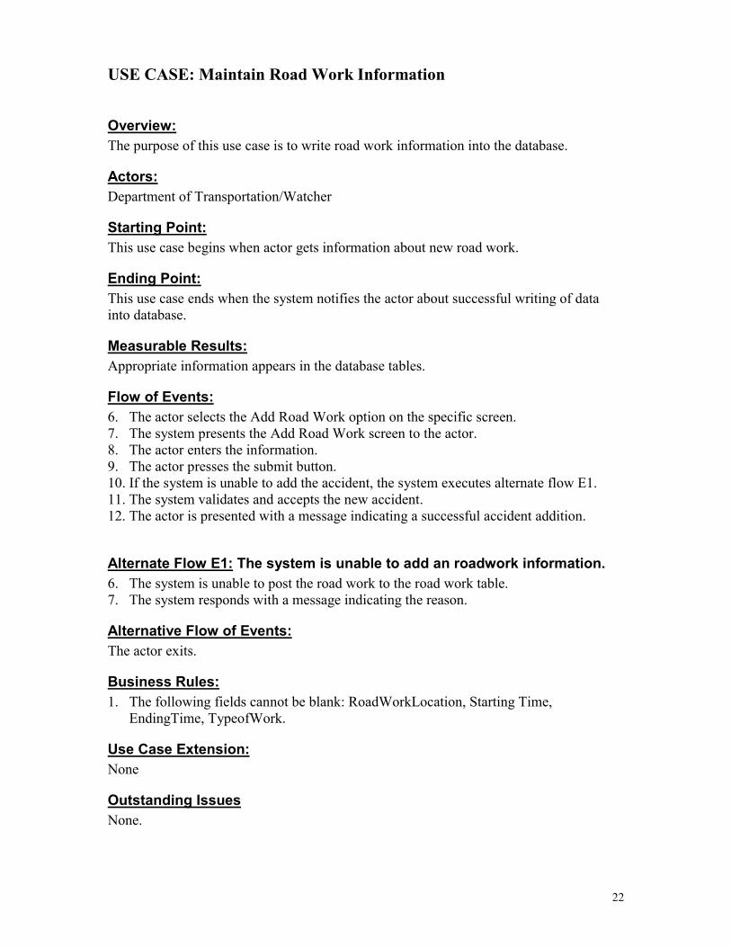
USE CASE: Maintain Road Work Information
Overview: The purpose of this use case is to write road work information into the database.
Actors: Department of Transportation/Watcher
Starting Point: This use case begins when actor gets information about new road work.
Ending Point: This use case ends when the system notifies the actor about successful writing of data into database.
Measurable Results: Appropriate information appears in the database tables.
Flow of Events: 6. The actor selects the Add Road Work option on the specific screen. 7. The system presents the Add Road Work screen to the actor. 8. The actor enters the information. 9. The actor presses the submit button. 10. If the system is unable to add the accident, the system executes alternate flow E1. 11. The system validates and accepts the new accident. 12. The actor is presented with a message indicating a successful accident addition.
Alternate Flow E1: The system is unable to add an roadwork information. 6. The system is unable to post the road work to the road work table. 7. The system responds with a message indicating the reason.
Alternative Flow of Events: The actor exits.
Business Rules: 1. The following fields cannot be blank: RoadWorkLocation, Starting Time,
EndingTime, TypeofWork.
Use Case Extension: None
Outstanding Issues None.
23
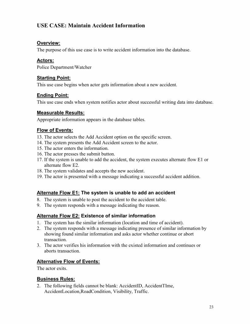
USE CASE: Maintain Accident Information
Overview: The purpose of this use case is to write accident information into the database.
Actors: Police Department/Watcher
Starting Point: This use case begins when actor gets information about a new accident.
Ending Point: This use case ends when system notifies actor about successful writing data into database.
Measurable Results: Appropriate information appears in the database tables.
Flow of Events: 13. The actor selects the Add Accident option on the specific screen. 14. The system presents the Add Accident screen to the actor. 15. The actor enters the information. 16. The actor presses the submit button. 17. If the system is unable to add the accident, the system executes alternate flow E1 or
alternate flow E2. 18. The system validates and accepts the new accident. 19. The actor is presented with a message indicating a successful accident addition.
Alternate Flow E1: The system is unable to add an accident 8. The system is unable to post the accident to the accident table. 9. The system responds with a message indicating the reason.
Alternate Flow E2: Existence of similar information 1. The system has the similar information (location and time of accident). 2. The system responds with a message indicating presence of similar information by
showing found similar information and asks actor whether continue or abort transaction.
3. The actor verifies his information with the existed information and continues or aborts transaction.
Alternative Flow of Events: The actor exits.
Business Rules: 2. The following fields cannot be blank: AccidentID, AccidentTIme,
AccidentLocation,RoadCondition, Visibility, Traffic.

24
Use Case Extension: None
Outstanding Issues None.

25
USE CASE Compute Primary/Secondary Reports
Overview: The purpose of this use case is to provide a system with regular reports based on information received from sensors or intermediate reports.
Actors: Primary/Secondary Data Mining Agent
Starting Point: This use case is started when it is time for agent to compute next report.
Ending Point: This use case ends when appropriate information has successfully written into the database.
Measurable Results: Appropriate information appears in database.
Flow of Events: 20. Actor accesses appropriate database (with information from sensor or including
intermediate reports), 21. computes the necessary report, 22. writes information to appropriate database, 23. if there is a need cleans raw data.
Alternate Flow E1: The agent is unable to retrieve or submit the data. 10. The agent is unable to retrieve “raw” or to write report into database. 11. The message with the reason is sent to administrator.
Alternative Flow of Events: None.
Business Rules: 1. The reports are computed on different regular bases stated by system manager.
Use Case Extension: None.
Outstanding Issues None.

26
USE CASE: Write Sensor Information
Overview: The purpose of this use case is to write information read by sensor (any: traffic, weather, road condition) into the database.
Actors: Sensor
Starting Point: This use case begins when sensor is ready (according to sensor or its software specification) to write.
Ending Point: This use case ends when the information read by sensor is successfully written into database.
Measurable Results: Appropriate information appears in the database tables.
Flow of Events: To be define.
Alternate Flow E1: The system is unable to write information from sensors. 12. The system is unable to post sensor information to the appropriate tables
(WeatherCondition, RoadCondition, TrafficInformation) 13. The system notifies administrator about the problem and its reason. 14. The system writes problem’s description and its reason to the log file.
Alternative Flow of Events: None.
Business Rules: To be defined.
Use Case Extension: None
Outstanding Issues Flow of Events should be defined according to sensors or their software specification. Business Rules may or may not be defined.

27
USE CASE Validate User
Overview: The purpose of this use case is to check authorized access to the system or database.
Actors: Police department, DOT, Emergency service
Starting Point: This use case is started when user logs on the system.
Ending Point: This use case ends when user is notified if he accesses the system or access is denied.
Measurable Results: The appropriate message is shown on the screen.
Flow of Events: 24. The user enters the password. 25. The system checks it. 26. The system provides user with the appropriate message about his access to system.
Alternative Flow of Events: The actor exits.
Business Rules: None.
Use Case Extension: None.
Outstanding Issues None.

28
USE CASE Send Information
Overview: The purpose of this use case is to send the information to the users on a regular base.
Actors: E-Mail Robot
Starting Point: This use case is started when it is time for e-mail robot to send information to the user.
Ending Point: This use case ends when appropriate information has successfully sent.
Measurable Results: None.
Flow of Events: 27. Actor accesses appropriate database, generates a messages and sends them to the
appropriate users.
Alternate Flow E1: The agent is unable to send information. 15. The agent is unable to send the information. 16. The message with the reason is sent to administrator.
Alternative Flow of Events: None.
Business Rules: None.
Use Case Extension: None.
Outstanding Issues None.

29
SPECIALIZED “REQUEST COMMON INFORMATION” USE CASE
Figure 3. (Specializes Request Common Information Use Case for Figure 2.)
Request Research Goal Information Request Common Information Request Transport Alternative
Request Existing Incidents
Request Weather Information
Request Traffic Information
Request a Route
Request Alternative Route
30
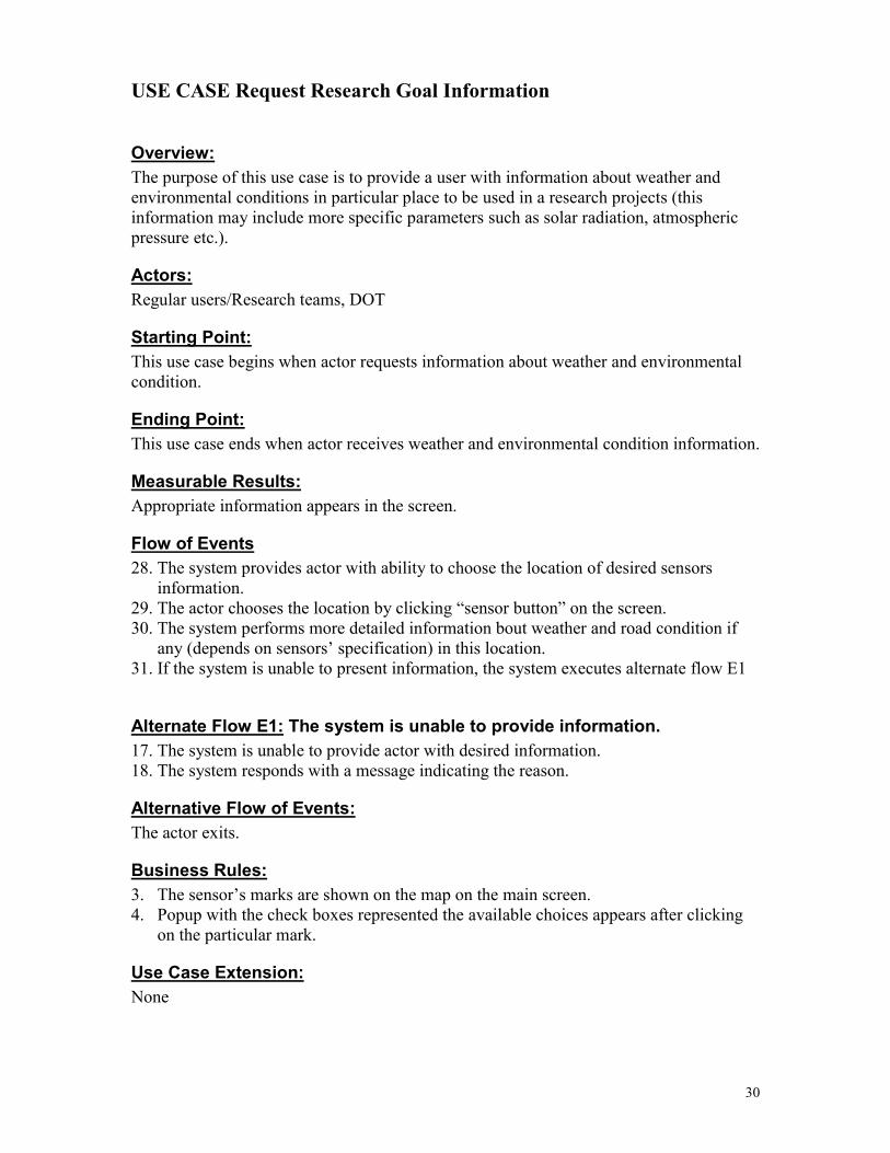
USE CASE Request Research Goal Information
Overview: The purpose of this use case is to provide a user with information about weather and environmental conditions in particular place to be used in a research projects (this information may include more specific parameters such as solar radiation, atmospheric pressure etc.).
Actors: Regular users/Research teams, DOT
Starting Point: This use case begins when actor requests information about weather and environmental condition.
Ending Point: This use case ends when actor receives weather and environmental condition information.
Measurable Results: Appropriate information appears in the screen.
Flow of Events 28. The system provides actor with ability to choose the location of desired sensors
information. 29. The actor chooses the location by clicking “sensor button” on the screen. 30. The system performs more detailed information bout weather and road condition if
any (depends on sensors’ specification) in this location. 31. If the system is unable to present information, the system executes alternate flow E1
Alternate Flow E1: The system is unable to provide information. 17. The system is unable to provide actor with desired information. 18. The system responds with a message indicating the reason.
Alternative Flow of Events: The actor exits.
Business Rules: 3. The sensor’s marks are shown on the map on the main screen. 4. Popup with the check boxes represented the available choices appears after clicking
on the particular mark.
Use Case Extension: None

31
Outstanding Issues 1. The degree of granularity information about weather and road condition based on sensors’ specification.

32
USE CASE Request Weather Information
Overview: The purpose of this use case is to provide a user with information about weather and environmental conditions in particular place.
Actors: Regular users/Research teams, Emergency service, DOT
Starting Point: This use case begins when actor requests information about a weather condition.
Ending Point: This use case ends when actor receives a weather condition information.
Measurable Results: Appropriate information appears in the screen.
Flow of Even 32. The system provides actor with ability to choose the location of desired sensors
information. 33. The actor chooses the location by clicking “sensor button” on the screen. 34. The system provides actor with ability to choose desired information from possible in
this location. 35. The actor chooses the desired information. 36. The actor is presented with the desired information. 37. If the system is unable to present information, the system executes alternate flow E1
Alternate Flow E1: The system is unable to provide information. 19. The system is unable to provide actor with desired information. 20. The system responds with a message indicating the reason.
Alternative Flow of Events: The actor exits.
Business Rules: 5. The sensor’s marks are shown on the map on the main screen. 6. Popup with the check boxes represented the available choices appears after clicking
on the particular mark.
Use Case Extension: Request information for research goals.
Outstanding Issues None.

33
USE CASE Request Traffic Information
Overview: The purpose of this use case is to provide a user with information about traffic conditions in a particular place.
Actors: Regular users/Research teams, Emergency service, DOT
Starting Point: This use case begins when actor presses “sensor mark” on the map on the main screen.
Ending Point: This use case ends when actor receives a weather condition information.
Measurable Results: Appropriate information appears in the screen.
Flow of Even 38. The system provides actor with ability to choose the location of desired sensors
information. 39. The actor chooses the location by clicking “sensor button” on the screen. 40. The system provides actor with ability to choose desired information from possible in
this location (weather, road condition, traffic). 41. The actor chooses the desired information. 42. The actor is presented with the desired information. 43. If the system is unable to present information, the system executes alternate flow E1
Alternate Flow E1: The system is unable to provide information. 21. The system is unable to provide the actor with desired information. 22. The system responds with a message indicating the reason.
Alternative Flow of Events: The actor exits.
Business Rules: 7. The sensor’s marks are shown on the map on the main screen. 8. Popup with the check boxes representing the available choices appears after clicking
on the particular mark.
Use Case Extension: None.
Outstanding Issues None.

34
USE CASE Request Existing Incidents
Overview: The purpose of this use case is to provide a user with information about any existing incident in the system.
Actors: Regular users/Research teams, Emergency service, DOT
Starting Point: This use case begins when actor chooses appropriate menu item.
Ending Point: This use case ends when actor receives requested information.
Measurable Results: Appropriate information appears in the screen.
Flow of Events: 44. The user chooses appropriate menu option. 45. The system provides the actor with information about existing at current moment and
affecting traffic incidents if any. 46. If the system is unable to present information, the system executes alternate flow E1
Alternate Flow E1: The system is unable to provide information. 23. The system is unable to provide the actor with the desired information. 24. The system responds with a message indicating the reason.
Alternative Flow of Events: The actor exits.
Business Rules: None.
Use Case Extension: None.
Outstanding Issues None.

35
USE CASE Request a Route.
Overview: The purpose of this use case is to provide a user with information about route from one specified point to another.
Actors: Regular users/Research teams, Emergency service, DOT
Starting Point: This use case begins when the user selects “Request a route” options.
Ending Point: This use case ends when user receives a direction from origin to destination and information about traffic conditions on his way.
Measurable Results: Appropriate information appears in the screen.
Flow of Events: 47. The user provides the system with information about start and end points of his way. 48. The system provides user with the shortest route and gives traffic information if any. 49. The system provides user with ability to print received information. 50. If there is an accident or some road-work and as a result traffic jam, the system
provides user with ability to request alternative road or transport alternative.
Alternate Flow E1: The system is unable to respond. 25. The system is unable to provide actor with desired information. 26. The system responds with a message indicating the reason.
Alternative Flow of Events: The actor exits.
Business Rules: 9. Input for the system should be not key sensitive.
Use Case Extension: 1. Request alternative route. 2. Request transportation alternative.
Outstanding Issues None.

36
USE CASE Request Alternative Route.
Overview: The purpose of this use case is to provide a user with information about a route from one specified point to another.
Actors: Regular users/Research teams, Emergency service, DOT
Starting Point: This use case may begin after the use case “Request a route” ends and user submits “Request alternative route” button.
Ending Point: This use case ends when user receives a direction from origin to destination and information about traffic conditions on the way.
Measurable Results: Appropriate information appears in the screen.
Flow of Events: 51. The user provides the system with information about start and end points of his way. 52. The system provides user with the shortest from other possible routes and gives
traffic information if any. 53. The system provides user with ability to print received information. 54. If there is an accident or some road-work and as a result traffic jam, the system
provides user with ability to request alternative road or transport alternative.
Alternate Flow E1: The system is unable to respond. 27. The system is unable to provide actor with desired information. 28. The system responds with a message indicating the reason.
Alternative Flow of Events: The actor exits.
Business Rules: 10. Input for the system should be not case sensitive.
Use Case Extension: 3. Request alternative route. 4. Request transportation alternative.
Outstanding Issues None.
37
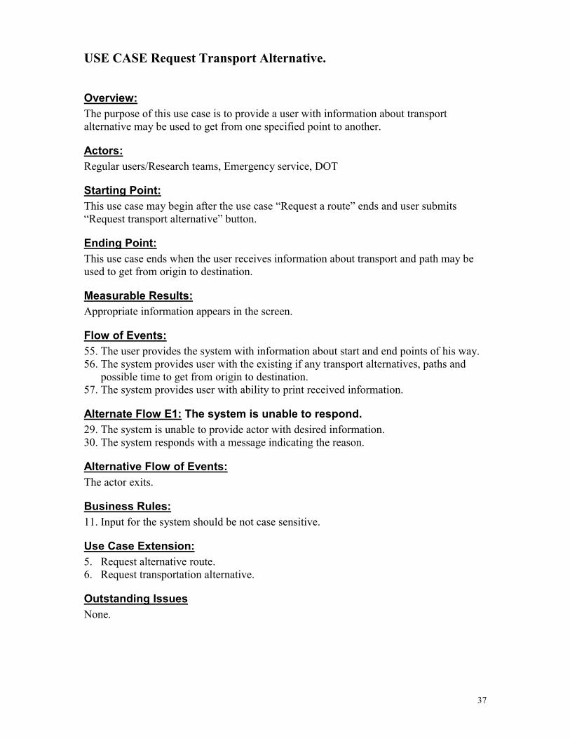
USE CASE Request Transport Alternative.
Overview: The purpose of this use case is to provide a user with information about transport alternative may be used to get from one specified point to another.
Actors: Regular users/Research teams, Emergency service, DOT
Starting Point: This use case may begin after the use case “Request a route” ends and user submits “Request transport alternative” button.
Ending Point: This use case ends when the user receives information about transport and path may be used to get from origin to destination.
Measurable Results: Appropriate information appears in the screen.
Flow of Events: 55. The user provides the system with information about start and end points of his way. 56. The system provides user with the existing if any transport alternatives, paths and
possible time to get from origin to destination. 57. The system provides user with ability to print received information.
Alternate Flow E1: The system is unable to respond. 29. The system is unable to provide actor with desired information. 30. The system responds with a message indicating the reason.
Alternative Flow of Events: The actor exits.
Business Rules: 11. Input for the system should be not case sensitive.
Use Case Extension: 5. Request alternative route. 6. Request transportation alternative.
Outstanding Issues None.
38
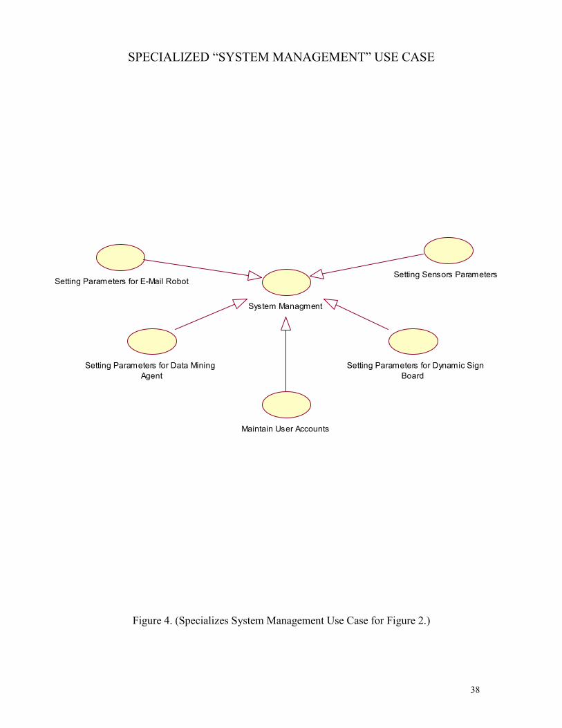
SPECIALIZED “SYSTEM MANAGEMENT” USE CASE
Figure 4. (Specializes System Management Use Case for Figure 2.)
Setting Parameters for E-Mail Robot
System Managment
Setting Sensors Parameters
Setting Parameters for Dynamic SignBoard
Maintain User Accounts
Setting Parameters for Data MiningAgent

39
USE CASE Setting Parameters for E-mail Robot.
Overview: The purpose of this use case is to set a system’s e-mail robot to send traffic and weather information to the users on some periodical base.
Actors: DOT
Starting Point: This use case is started when user chooses the appropriate menu item.
Ending Point: This use case ends when information with appropriate parameters and properties has successfully written into database.
Measurable Results: Appropriate information appears in database and the e-mail robot is configured to be ready to send information.
Flow of Events: 58. User chooses appropriate menu function. 59. The system displays the specific form to be filled. 60. User fills the form and submits the information.
Alternate Flow E1: The system is unable to perform user’s request. 1. User does not change the previous parameters. 2. User exits.
Alternative Flow of Events: None.
Business Rules: None.
Use Case Extension: None.
Outstanding Issues None.

40
USE CASE Setting Parameters for Data Mining Agent.
Overview: The purpose of this use case is to set a system’s Primary and Secondary Data Mining Agent to compute regular reports based on sensors’ raw information and previous reports.
Actors: DOT
Starting Point: This use case is started when user chooses the appropriate menu items.
Ending Point: This use case ends when information with appropriate parameters and properties has successfully written into database.
Measurable Results: Appropriate information appears in database and Data Mining Agents configured to be ready to compute information.
Flow of Events: 61. User chooses appropriate menu function. 62. The system displays the specific form to be filled. 63. User fills the form and submits the information.
Alternate Flow E1: The system is unable to perform the user’s request. 3. User does not change the previous parameters. 4. User exits.
Alternative Flow of Events: None.
Business Rules: None.
Use Case Extension: None.
Outstanding Issues None.

41
USE CASE: Maintain Users’ Accounts
Overview: The purpose of this use case is to manage users’ accounts and to assign their rights and privileges.
Actors: DOT
Starting Point: This use case begins when system manager (administrator) chooses the appropriate option in the user menu to create, delete or change users’ accounts.
Ending Point: This use case ends when the system manager (administrator) achieves his goals.
Measurable Results: 1. User account information is consistent up to date and the appropriate information is written into database.
Flow of Events: 1. Manager chooses the appropriate action (manage existing accounts or create new
accounts). 2. If the activity selected is to manage existing accounts, the system displays form with
written information and provides Manager with ability to edit or delete existing information.
3. If the activity selected is to create new account, the system displays the form to be filled.
Alternative Flow of Events: None.
Business Rules: None.
Use Case Extension: None.
42
USE CASE Setting Parameters for Dynamic Sign Board.
Overview: The purpose of this use case is to set Information (Dynamic Sign) Board to receive traffic and weather information in a regular basis.
Actors: DOT
Starting Point: This use case is started when user chooses the appropriate menu item.
Ending Point: This use case ends when information with appropriate parameters and properties has successfully written into database.
Measurable Results: Appropriate information appears in database and Information Board configured to be ready to work.
Flow of Events: 64. User chooses appropriate menu function. 65. The system displays the specific form to be filled. 66. User fills the form and submits the information.
Alternate Flow E1: The system is unable to perform user’s request. 5. User does not change the previous parameters. 6. User exits.
Alternative Flow of Events: None.
Business Rules: None.
Use Case Extension: None.
Outstanding Issues None.

43
USE CASE Setting Sensors’ Parameters.
Overview: The purpose of this use case is to set sensors send traffic and weather information to the system on some periodic base.
Actors: DOT
Starting Point: This use case is started when user chooses the appropriate menu item.
Ending Point: This use case ends when information with appropriate parameters and properties has successfully written into database.
Measurable Results: Appropriate information appears in database and the sensor is configured to send information.
Flow of Events: 67. User chooses appropriate menu function. 68. The system displays the specific form to be filled. 69. User fills the form and submits the information.
Alternate Flow E1: The system is unable to perform user’s request. 7. User does not change the previous parameters. 8. User exits.
Alternative Flow of Events: None.
Business Rules: None.
Use Case Extension: None.
Outstanding Issues None.

44
SPECIALIZED “MAINTAIN GENERAL INFORMATION” USE CASE
Figure 5. (Specializes Maintain General Information Use Case for Figure2.)
Maintain Trouble Report InformationMaintain General Information
Maintain Support Service Information
Maintain Location Information
Maintain SensorInstrument Information
Maintain VideoCamera Information
45
USE CASE: Maintain Trouble Report Information
Overview: The purpose of this use case is to maintain trouble report information (information about breakages of sensors, cameras) in the database.
Actors: DOT
Starting Point: This use case begins when user chooses appropriate option in the user menu.
Ending Point: This use case ends when the user selects activity QUIT.
Measurable Results: Appropriate information can be written, edited or deleted from appropriate database tables.
Flow of Events: 4. User chooses the appropriate menu item. 5. The system displays the table containing all records. 6. If the activity selected is ADD, the system displays the TroubleReport screen where
user can enter new records and then submit new information. 7. If the activity selected is EDIT, the system displays the TroubleReport screen where
user can edit records. 8. If the activity selected is DELETE, the system displays confirmation window and
then delete information.
Alternate Flow E1: The system is unable to perform users request. 31. The system is unable to perform users request. 32. The system notifies administrator about the problem and its reason. 33. The system writes problem’s description and its reason to the log file.
Alternative Flow of Events: None.
Business Rules: 1. The input should be not case sensitive.
Use Case Extension: None

46
USE CASE: Maintain Location Information
Overview: The purpose of this use case is to maintain location information in the database.
Actors: DOT
Starting Point: This use case begins when user chooses appropriate option in the user menu.
Ending Point: This use case ends when the user selects activity QUIT.
Measurable Results: Appropriate information can be written, edited or deleted from appropriate database tables.
Flow of Events: 9. User chooses the appropriate menu item. 10. The system displays the table containing all records. 11. If the activity selected is ADD, the system displays the location screen where user can
enter new records and then submit new information. 12. If the activity selected is EDIT, the system displays the location screen where user
can edit records. 13. If the activity selected is DELETE, the system displays confirmation window and
then delete information.
Alternate Flow E1: The system is unable to perform users request. 34. The system is unable to perform users request. 35. The system notifies administrator about the problem and its reason. 36. The system writes problem’s description and its reason to the log file.
Alternative Flow of Events: None.
Business Rules: 2. The input should be not key sensitive.
Use Case Extension: None
Outstanding Issues None
47
USE CASE: Maintain Sensor Instrument Information
Overview: The purpose of this use case is to maintain Sensor Intsrument information in the database.
Actors: DOT
Starting Point: This use case begins when user chooses appropriate option in the user menu.
Ending Point: This use case ends when the user selects activity QUIT.
Measurable Results: Appropriate information can be written, edited or deleted from appropriate database tables.
Flow of Events: 14. User chooses the appropriate menu item. 15. The system displays the table containing all records. 16. If the activity selected is ADD, the system displays the SensorInstrument screen
where user can enter new records and then submit new information. 17. If the activity selected is EDIT, the system displays the SensorInstrument screen
where user can edit records. 18. If the activity selected is DELETE, the system displays confirmation window and
then delete information.
Alternate Flow E1: The system is unable to perform users request. 37. The system is unable to perform users request. 38. The system notifies administrator about the problem and its reason. 39. The system writes problem’s description and its reason to the log file.
Alternative Flow of Events: None.
Business Rules: 3. The input should be not key sensitive.
Use Case Extension: None
Outstanding Issues None
48
USE CASE: Maintain Video Camera Information
Overview: The purpose of this use case is to maintain Video Camera information (description) in the database.
Actors: DOT
Starting Point: This use case begins when user chooses appropriate option in the user menu.
Ending Point: This use case ends when the user selects activity QUIT.
Measurable Results: Appropriate information can be written, edited or deleted from appropriate database tables.
Flow of Events: 19. User chooses the appropriate menu item. 20. The system displays the table containing all records. 21. If the activity selected is ADD, the system displays the VideoCamera screen where
user can enter new records and then submit new information. 22. If the activity selected is EDIT, the system displays the VideoCamera screen where
user can edit records. 23. If the activity selected is DELETE, the system displays confirmation window and
then delete information.
Alternate Flow E1: The system is unable to perform users request. 40. The system is unable to perform users request. 41. The system notifies administrator about the problem and its reason. 42. The system writes problem’s description and its reason to the log file.
Alternative Flow of Events: None.
Business Rules: 4. The input should be not case sensitive.
Use Case Extension: None

49
Outstanding Issues None

50
USE CASE: Maintain Support Service Information
Overview: The purpose of this use case is to maintain support service information in the database.
Actors: DOT
Starting Point: This use case begins when user chooses the appropriate option in the user menu.
Ending Point: This use case ends when the user selects activity QUIT.
Measurable Results: Appropriate information can be written, edited or deleted from appropriate database tables.
Flow of Events: 24. User chooses the appropriate menu item. 25. The system displays the table containing all records. 26. If the activity selected is ADD, the system displays the SupportServise screen where
user can enter new records and then submit new information. 27. If the activity selected is EDIT, the system displays the SupportServise screen where
user can edit records. 28. If the activity selected is DELETE, the system displays confirmation window and
then delete information.
Alternate Flow E1: The system is unable to perform users request. 43. The system is unable to perform users request. 44. The system notifies administrator about the problem and its reason. 45. The system writes problem’s description and its reason to the log file.
Alternative Flow of Events: None.
Business Rules: 5. The input should be not case sensitive.
Use Case Extension: None

51
MAJOR PARTICIPATING CLASSES
The arrows show referential constraints within the database
Figure 6
RoadConditionDate : dateTime : timeSurfaceTemperature : floatRoadCondition : varchar(16)PavementCondition : varchar(16)SubsurfaceTemperature : floatPresenceOfSnowAndItsDepth : varchar(16)FreezingPoint : floatConductivivityOfRunoffWater : floatSensorID int
TrafficInformationDate : dateTime : timeSpeedOfVehicle : floatWeghtOfVehicle : floatDeviceID : int
RoadWorkInformationRoadWorkIocation : varchar(64)StartDate : dateStartTime : timeEndDate : dateEndTime : timeTypeOfWork : varchar(64)ID : int
TroubleReportTroubleReportID : intTroubleReportDate : dateTroubleReportTime : timeDeviceID : intReason : varchar(64)RepareDate : date
InstrumentSensorID : intDescription : varchar(16)Location ID : intName : varchar(16)
WeatherConditionDate : dateTime : timeAirTemperature : floatWindSpeed : floatVisibility : floatPrecipitation : varchar(16)WindGusts : floatWindDerection : varchar(16)AtmosphericPressure : floatRelativeHumidity : floatSolarRadiation : floatSensorID int
LocationState : char(2)RoadID : varchar (4)RoadType : varchar(16)SurfaceType : varchar(16)SurfaceSickness : varchar()ID : int
DeilyQuarterWeatherInformationLocationID : intDate : dateTime : timeAverageTemperature : floatAverageWindSpeed : floatPrecipitation : varchar(16)AverageAtmoshericPressure : floatAverageSolarRadiation : floatRelativeHumidity : floatWindDerection : varchar(16)Visibility : varchar(16)
Video CameraID : intDescription : varchar(16)LocationID : intName : varchar (16)
DailyDesignedQuarterValueLocationID : intDate : dateTime : timeNumberOfVehicles : intSpeedofVehicles : float
DailyDesignedHourValueLocationID : intDate : dateTime : timeNumberofVehicles : INTSpeedofVehicles : FLOAT
DeilyQuarterRoadConditionInformationLocationID : intDate : dateTime : timeAverageSurfaceTemperature : floatRoadCondition : varchar(16)PavementCondition : varchar(16)AverageSubsurfaceTemperature : floatFreezingPoint : floatConductivityofRunningWater : float
PeakHourLocationID : intDate : dateAMHour : timeAMHourNumberofVehicles : intAMSpeedofVehicles : floatPMHour : timePMHourNumberofVehicle : intPMHourSpeedofVehicles : float
AverageWeekendTrafficVolumesLocationID : intDate : dateNumberofVehicles : intSpeedofVehicles : float
SeasonalTrafficVariationLocationID : intSasonID : intNumberofVehicles : intSpeedofVehicles : float
AnualAverageDailyTrafficLocationID : intDate : dateNumberofVehicles : intSpeedofVehicles : float
AccidentInformationAccidentID : intAccidentDate : dateAccidentTime : timeAccidentLocation : varchar(64)AccidentName : varchar(32)RoadCondition : varchar(16)Visibility : floatTraffic : float
SupportServiceName : varchar(32)Address : varchar(128)Phone : char(16)Fax : char(16)E-mail address : varchar(64)Contact personal : varchar(64)URL : varchar(265)ID : int
