rgx3500 - generator - small engines | pumps | generators ... · pdf filehow to use this parts...
TRANSCRIPT

HOW TO USE THIS PARTS CATALOG
1. Reference numbers with an asterisk Reference numbers marked with an asterisk indicate that the particular part is available only as a complete set or assembly.
Example :
If the reference number is marked with an asterisk and the description of the part states that certain items are included,this means that those included items cannot be ordered separately and must be purchased as a complete assembly. -
2. Description of interchangeability and execution columns Example : Interchangeability column Example : Execution column
3 Items interchangeable between the - 010000 new and old parts. 010001 -
7 Items not interchangeable between J the new and old parts. 010000. 1 Items conditionally interchangeable Serial No.
X For use for Serial No. up to
4 y between the new and old parts which are subject to the description in the execution column.
For use for Serial No. from 010001.
Example : Interchangeable I
~ _ _
Part B Part A
Part C Part B Part A
1 3 Part A I
Part B
4 Y Part A 1.
Executiod Explanation ~~
This indicates that Part A changed to Part B fo r generators 020000 - with serial numbers from 20000, and that they are
interchangeable.
This indicates that Part A changed to Part B fo r generators
020000 - 01 5000 -
with serial numbers from 15000, and .that they are not interchangeable.Also, Part B changed to Part C for generators with serial numbers from 20000 and that they
I are interchangeable.
020000 - This indicates that Part A is a new part for generators with serial numbers with from 20000.
- 030000~ This indicates that Part B is no longer used for generator with serial numbers from 30001.
This indicates that Part A changed to Part B for generators with serial numbers from 20000, and that they are conditionally interchangeable. (See NOTE described. at the
020000 -
I end of the section.)
3. The contents of this parts catalog are subject to revision without notice.TO INSURE PROMPT AND ACCURATE SERVICE, ALSO THE FOLLOWING INFORMATION MUST
BE GIVEN.
1. State exactly the quantity of each part and its part numbers.
2. Clearly state whether parts are to be shipped by express, freight or parcel post.
3. State the exact mailing address.
Page
GENERATOR PARTS
FIG. 1 GENERATOR . . . . . . . . . . . . . . . . . . . . . . . . . . . . . . . . . . . . . . . . . . . . . . . . . . . . . . . . . . . . . . . . . . . . . . . 1
FIG. 2 PIPE FRAME and FUEL TANK . . . . . . . . . . . . . . . . . . . . . . . . . . . . . . . . . . . . . . . . . . . . . . . . . . . . 3
FIG. 3-2 CONTROL BOX (1 10V, 120V) . . . . . . . . . . . . . . . . . . . . . . . . . . . . . . . . . . . . . . . . . . . . . . . . . . . . . 13
FIG.3-3 CONTROL BOX (11 OV/220V) . . . . . . . . . . . . . . . . . . . . . . . . . . . . . . . . . . . . . . . . . . . . . . . . . . . . . 19
FIG.3-6 CONTROL BOX (U. S.A.. 60 Hz-120 V/240V. NEMA) . . . . . . . . . . . . . . . . . . . . . . . . . . . . . . . 31
ENGINE PARTS
FIG. 4 CRANKCASE GROUP . . . . . . . . . . . . . . . . . . . . . . . . . . . . . . . . . . . . . . . . . . . . . . . . . . . . . . . . . . . . . . 51
FIG. 5 CRANK and PISTON GROUP . . . . . . . . . . . . . . . . . . . . . . . . . . . . . . . . . . . . . . . . . . . . . . . . . . . . . . 53
FIG. 6 INTAKE and EXHAUST GROUP . . . . . . . . . . . . . . . . . . . . . . . . . . . . . . . . . . . . . . . . . . . . . . . . . . . 55
FIG. 7 GOVERNOR. OPERATE GROUP . . . . . . . . . . . . . . . . . . . . . . . . . . . . . . . . . . . . . . . . . . . . . . . . . . . . 57
FIG. 8 COOLING and STARTING GROUP . . . . . . . . . . . . . . . . . . . . . . . . . . . . . . . . . . . . . . . . . . . . . . . . . 59
FIG. 9 FUEL. LUBRICANT GROUP . . . . . . . . . . . . . . . . . . . . . . . . . . . . . . . . . . . . . . . . . . . . . . . . . . . . . . . 61
FIG.1O ELECTRIC DEVICE GROUP . . . . . . . . . . . . . . . . . . . . . . . . . . . . . . . . . . . . . . . . . . . . . . . . . . . . . . . . 63
FIG. 11 OIL SENSOR GROUP . . . . . . . . . . . . . . . . . . . . . . . . . . . . . . . . . . . . . . . . . . . . . . . . . . . . . . . . . . . . . . 65
FIG.12 STARTING MOTOR GROUP (ELECTRIC STARTER PARTS) ““............-.........67
OPTIONAL PARTS
FIG. 14 WHEEL, HANDLE and HANGER . . . . . . . . . . . . . . . . . . . . . . . . . . . . . . . . . . . . . . . . . . . . . . . . . . . 71
FIG. 1 GENERATOR
- 1 -
-2-

FIG. 2 PIPE FRAME and FUEL TANK
!
‘9 L
-3-

FIG. 2 PIPE FRAME and FUEL . . . TANK- ~
P a r t s N u m b e r
3 8 9 - 5 6 0 6 1 - 0 8
3 8 9 - 5 6 0 6 9 - 0 8
3 8 9 - 5 6 0 6 5 - 0 8
3 8 9 - 5 6 0 7 1 - 0 8
3 8 9 - 5 8 5 8 0 - 0 8
3 8 9 - 5 8 5 8 4 - 0 8
3 8 9 - 5 9 1 7 3 - 0 8
3 8 9 - 5 9 2 1 3 - 0 8
0 1 1 - 0 0 6 0 0 - 8 0
0 - 1 1 - 1 0 0 6 1 - 2 0
3 5 2 - 5 7 0 4 1 - 1 8
3 5 2 - 5 7 0 4 2 - 1 8
0 0 2 - 3 8 0 8 0 - 0 0
3 8 9 - 5 4 4 1 1 - 0 8
0 0 1 - 1 3 0 6 4 - 0 0
3 8 9 - 5 4 3 9 8 - 0 8
0 0 2 - 1 7 0 6 0 - 0 0
2 3 4 - 6 9 0 0 1 - 0 1
3 8 9 - 5 9 1 5 8 - 0 8
3 8 7 - 5 9 3 2 6 - 0 8
3 7 7 - 9 2 5 0 0 - 0 3
3 8 7 - 5 9 3 2 7 - 0 8
3 9 1 - 9 4 0 0 1 - 0 3
0 4 3 - 0 4 3 0 0 - 1 5
0 6 4 - 1 3 6 0 0 - 1 0
2 2 7 - 6 6 0 0 1 - 0 3
0 6 4 - 8 0 0 0 4 - 0 0
0 1 4 - 5 0 5 0 0 - 4 0
3 5 9 - 5 9 9 8 8 - 0 8
3 5 2 - 5 4 3 2 7 - 0 8
0 5 6 - 1 1 7 0 0 - 1 0
0 8 5 - 1 1 1 0 0 - 0 0
3 8 9 - 5 4 4 1 4 - 0 8
3 4 1 - 0 0 5 0 8 - 0 0
3 3 2 - 0 0 0 5 0 - 0 8
3 8 9 - 5 6 0 7 3 - 0 8
- . . .: . .. .
. - > " . .1". .~
D e s c r i ' p t i o n 3' tl
PI PE FRAME, c o m p 1 . For Recoil starter type 1
P I PE FRAME. c o m p 1. For Electric starter type 1 PIPE FRAME, c o m p l . 1
For U.S.A., Recoil starter type PIPE FRAME. c o m p 1 . 1
For U.S.A., Electric starter type
SIDE PLATE, c o m p l . Includes item 3
1 SIDE PLATE, c o m p l . Includes item 3
1
For U.S.A. LABEL
2 BATTERY FRAME, c o m p 1. 1 SPRING WASHER 1 SCREW 1 EARTH CORD 1 RUBBER PIPE (11. 5 4 x 1 7 . 5 4 X 2 3 0 m m ) 2 HOSE CLAMP 4 RUBBER WASHER 4 FLANGE BOLT 2 SCREW, c o u n t e r h e a d 1 FUEL GAUGE. c o m p l . 1 PLUG COVER 1 FUEL FILTER 1 FUEL TANK CAP, c o m p l . 1 LABEL. b r u s h l e s s For U.S.A. 1 LABEL, c a u t i o n For FRANCE 1 LABEL, c a u t i o n 1 LABEL, o p e r a t i o n For FRANCE 1 LABEL, o p e r a t i o n 1 FUEL TANK, c o m p l . 1 NUT 1 SPACER 1 BOLT a n d WASHER ASS' Y 1 STOPPER PLATE 4 FLANGE NUT 2 RUBBER MOUNT UNIT, engineside 2 RUBBER MOUNT UN IT. generator side 1 BOLT a n d WASHER ASS' Y 2 FLANGE BOLT 1 LABEL For U.S.A. 1
For Electric starter type
I I 1
When ordering parts ; Always give the Model, Specification and Serial Wumber of Generator.
- 4 -
Interchangeability r Execution
F
I
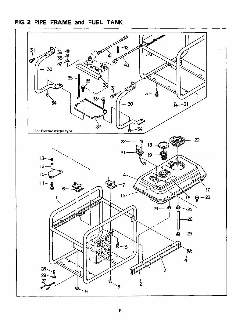
FIG. 2 PIPE FRAME and FUEL TANK
-5-

. -
FIG. 2 PIPE FRAME and FUEL TANK- Interchangeability -
Ref. KO.
i .
P a r t s N u m b e r D e s c r i p t i o n Execution
30 3 8 9 - 5 6 0 7 4 - 0 8 i BATTERY FRAME, c o m p l . For U.S.A., Electric starter type
31 0 0 1 - 1 4 0 8 2 - 0 0 B O L T a n d W A S H E R A S S ' Y 1 For Electric starter type
32 3 8 9 - 5 4 4 5 0 - 0 8 B A T T E R Y B A S E For Electricstarter t y p e
32 3 8 9 - 5 4 4 5 1 - 0 8 B A T T E R Y B A S E ForU.S.A.,Electricstartertype 33 0 0 1 - 1 1 0 6 3 - 5 0 B O L T a n d W A S H E R A S S ' Y
For Electric starter type
3 4 1 0 0 2 - 1 7 0 6 0 - 0 0 I NUT For Electric starter type I 4
3 5 1 3 5 3 - 5 9 9 2 1 - 0 8 1 BATTERY B O L T For Electric starter t y p e I 2 I 36 3 8 5 - 5 4 3 8 2 - 0 8 B A T T E R Y R E T A I N E R ForElectricstarter t y p e 1
37 3 8 5 - 5 4 4 1 6 - 0 8 B A T T E R Y S U P P O R T ForElectricstartertype 2 38 0 0 3 - 2 0 0 6 0 - 0 0 S P R I N G W A S H E R For Electric starter type 2
39 0 0 2 - 1 7 0 6 0 - 0 0 I N U T For Electric starter type 2
40 3 8 9 - 5 4 4 5 3 - 0 8 B A T T E R Y C O R D (-1 For Electric starter t y p e 1 , 41, 3 8 9 - 5 4 4 5 2 - 0 8 B A T T E R Y C O R D (+) For Electric starter t y p e 1
421 0 5 6 - 6 0 0 0 2 - 5 0 1 C L A M P For Electric starter type I 1 I
I
I I I I
!
L I
E
-6-
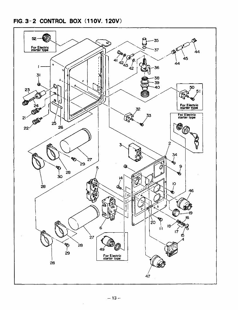
FIG. 3- 2 CONTROL BOX (1 1 OV, 120V)
I 29 I 28
\! I \
6
For Electric starter type
32
47
- 13 -
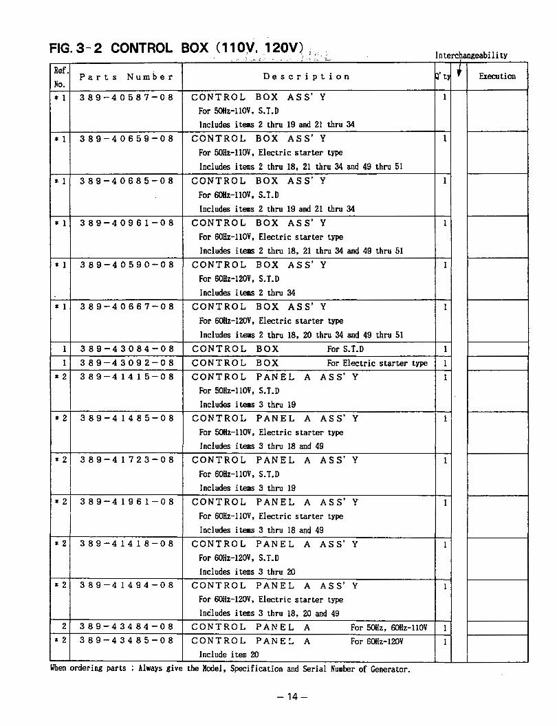
FIG. 3- 2 CONTROL
Ref.j P a r t s N u m b e r ti0.
Execution D e s c r i p t i o n J P ' 4 +
1
- 1
~ - 1
C O N T R O L BOX A S S ' Y For 50Hz-l10V, S.T.D Includes items 2 thru 19 and 21 thru 34
C O N T R O L BOX A S S ' Y For 50Hz-l1OV, Electric starter type Includes items 2 thru 18, 21 thru 34 and 49 thru 51
C O N T R O L BOX A S S ' Y For MHz-llOV, S.T.D Includes itens 2 thru 19 and 21 thru 34
* 1 389-40659-08
* 1 389-40685-08
* 1 389-40961-08 C O N T R O L BOX A S S ' Y 1 For 6OHz-l10V, Electric starter type Includes items 2 thru 18, 21 thru 34 and 49 thru 51
C O N T R O L BOX A S S ' Y 1 For 60Hz-l20V, S.T.D Includes items 2 thru 34
C O N T R O L BOX A S S ' Y 1 For 60Hz-l2OV, Electric starter type Includes items 2 thru 18, 20 thru 34 and 49 thru 51
C O N T R O L BOX For S.T.D 1 C O N T R O L BOX For Electric starter type 1 C O N T R O L P A N E L A A S S ' Y 1
For SO&-11OV, S.T.D Includes items 3 thru 19
I
1 1 389-43084-08 I
1 1 389-43092-08
* 2 389-41485-08 C O N T R O L P A N E L A A S S ' Y For 5oHz-llOV, Electric starter type Includes items 3 thru 18 and 49
I
'21 389-41723-08
I 121 389-41961-08
I
C O N T R O L P A N E L A A S S ' Y For 6OHz-l10V, S.T.D Includes items 3 thru 19
1
C O N T R O L P A N E L A A S S ' Y For 6OHz-llOV, Electric starter type Includes items 3 thru 18 and 49
1
I
* 2 389-41418-08 C O N T R O L P A N E L A A S S ' Y I 1 1 For 60Hz-l20V, S.T.D I I Includes items 3 thru 20
C O N T R O L P A N E L A A S S ' Y * 2 389-41494-08 For 60Hz-l2OV, Electric starter type Includes items 3 thru 18. 20 and 49 .t"--.. 2 389-43484-08
I
C O N T R O L P A N E L A For %Hz, MHz-1lOV f 1 C O N T R O L P A N E L . A For 60Hz-120V l i l ~~ ~
Include item 20 ! I when ordering parts : Always
- 14-
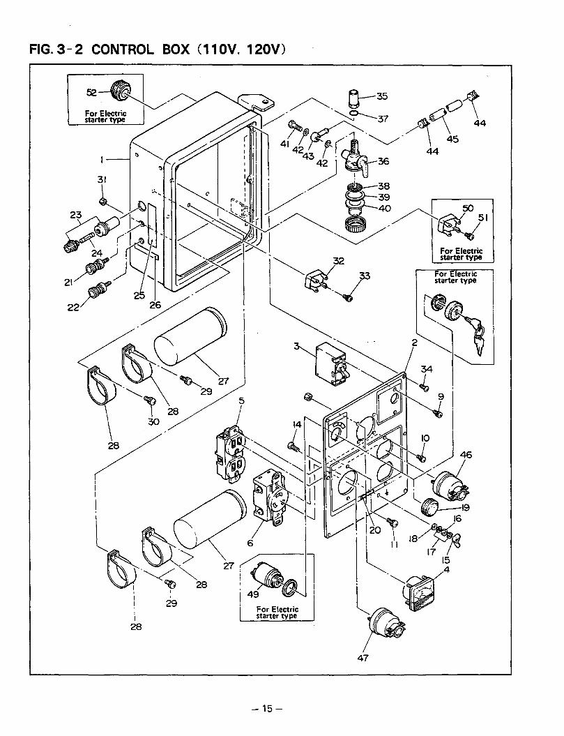
FIG. 3- 2 CONTROL BOX (1 1 OV, 120V)
I 1
! 29
28 I
14
J
47
- 15 -
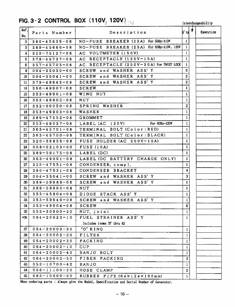
FIG. 3- 2 CONTROL BOX (1 1 OV, 12OV) -
.. .. .
. . I . .r< .~ Interchangeability
Ref.
No. P a r t s Number
NO-FUSE BREAKER (25A) For 60H~-llOV, 120V 1 389-4 5666-08 3 NO-FUSE BREAKER (22A) For50Hz-llOV 1 380-45639-08 3
Description 2' t
4 AC RECEPTACLE (125V-15A) 1 378-45737-08 5 ,
AC VOLTMETER(15OV) 1 320-75127-08
4135-7-445-703-08 1 A C RECEPTACLE (250V-30A) ForlWISTLOCKI 1 91 004-35030-60 I SCREW a n d WASHER ASS'Y 1 2
101 004-35041-00 I SCREW a n d WASHER ASS'Y 1 2 11
WING NUT 1 353-49901-08 15 SCREW 1 356-49907-08 14 SCREW a n d WASHER ASS'Y 2 379-49943-08
LABEL(AC 12OV) For 6OHz-120V 1 353-49037-08 20 GROMMET 1 389-47552-08 19 WASHER 1 353-49903-08 18 SPRING WASHER 2 332-00050-08 17 NUT 1 353-49902-08 16
211 363-45701-08 1 TERMINAL BOLT (Co1or:RED) I 1 221 363-45700-08 I TERMINAL BOLT(Co1or:BLACK) I 1 2 3 1 320-59855-08 I FUSE HOLDER(AC 250V-10A) 1 1 241 008-02103-00 I FUSE (lOA) I 1 2 5 1 389-59175-08 I LABEL (DC) I 1 2 6 1 363-49091-08 I LABEL(DC BATTERY CHARGE ONLY) 1 1 2 7 j 329-47551-08 I CONDENSER. C O ~ D ~ . I 1 28
. NUT, j o i n t 053-30900-20 35 SCREW 6 353-49904-08 34 SCREW a n d WASHER ASS'Y 1 353-59949-08 33
353-45804-08 ! DIODE STACK ASS'Y 1 32 NUT I 1 389-59990-08 31 SCREW a n d WASHER ASS'Y I 1 389-59989-08 30 SCREW and WASHER ASS' Y 1 3 004-35041-00 29 CONDENSER BRACKET 1 4 380-47531-08
+x( 064-20023-10 i FUEL STRAINER ASS'Y I I
i Includes items 37 thru 42 3 7 1 064-20003-30
BANJO 1 4 3 1 052-10700-42 FIBER PACKING 2 421 064-20002-50
064-20002-40 BANJO BOLT 1 41 064-20002-10 CUP 1 40
, PACKING 1 064-20002-30 49 FILTER 1 064-20002-20 38 "0" RING ! 1
441 056-11100-20 RUBBER PIPE(6@x12@X190mm) 1 4 5 1 085-10600-00 HOSE CLAMP 2
hen ordering parts ; Always give the Hodel, Specification and Serial Number of Generator.
- 16 -
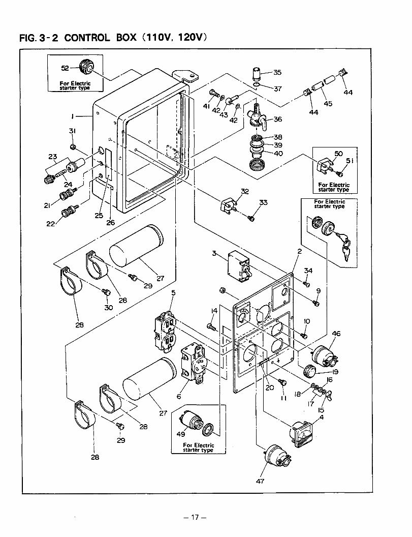
FIG. 3- 2 CONTROL BOX (1 1 OV, 120V)
I
i
28 I For Electric
47
-..
- 17 -

- . . ..
FIG. 3- 2 CONTROL BOX (1 1 OV, 120V.1, . . !::. Interchangeability
4 6 1 3 58-95002-03 I A C P L U G ( 1 2 5 V - 1 5 A ) 1 2 1 ! I I
1 4 7 1 353-45705-08 I A C P L U G ( T W I S T L O C K ) 1 1 1 - 4 9 ] 066-00001-11 I K E Y S W I T C H A S S ' Y ForElectricstartertmI 11
I
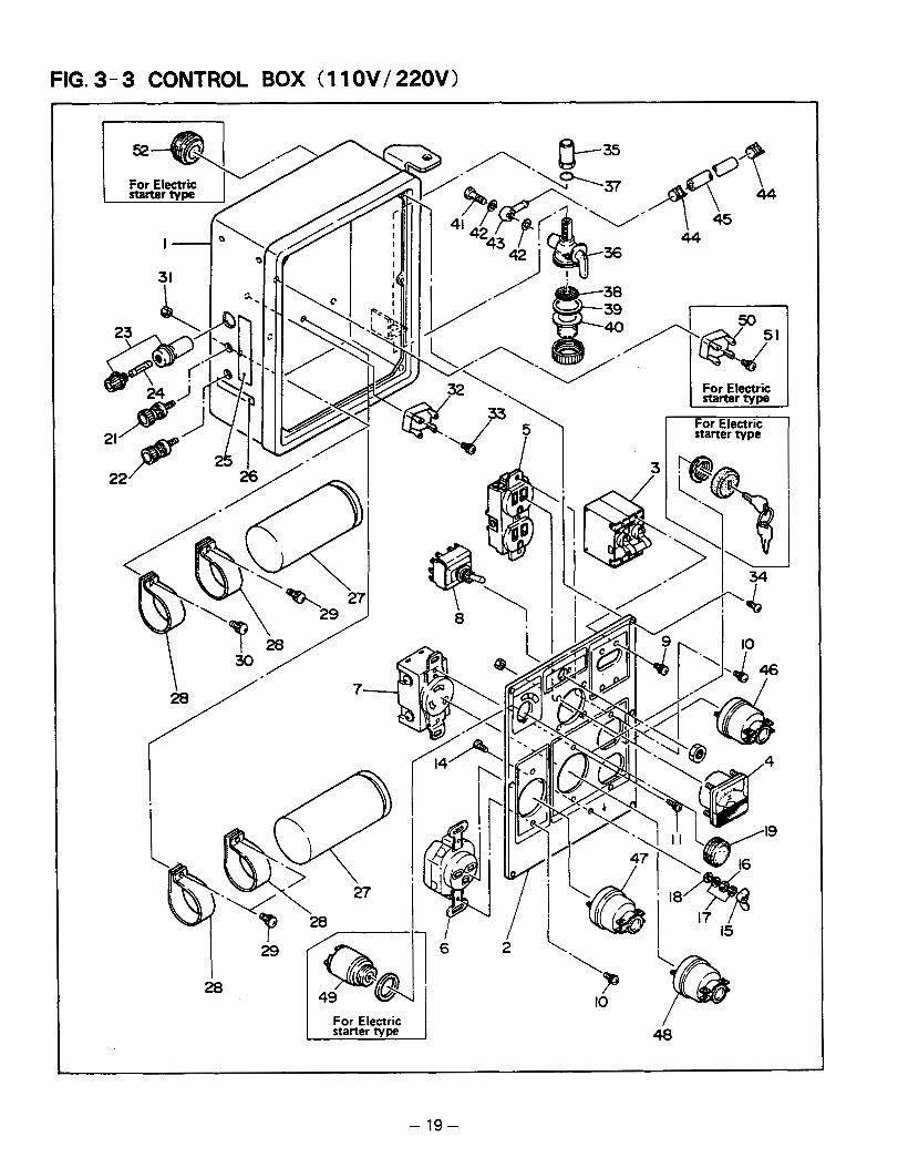
FIG. 3- 3 CONTROL BOX (1 1 OV/ 220V)
8 ! i
starter type
\ /
15
I For Electric I starter lype 48
- 19-
. - -
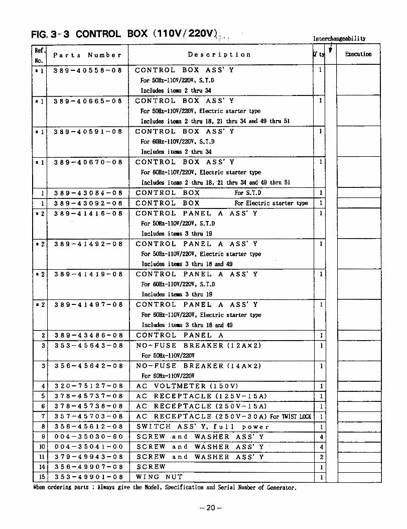
FIG. 3 - 3 CONTROL BOX ( 1 1 OV / 220V.) . . . -.. -1 ! .
Ref. NO.
* 1 CONTROL BOX ASS'Y 1 389-40558-08 For 5OHz-l10V/22OV, S.T.D Includes items 2 thru 34
Parts Number D e s c r i p t i o n T t
* 1 CONTROL BOX ASS'Y 1 389-40665-08 For ~Ez-l10V/22OV, Electric starter type Includes items 2 thru 18, 21 thru 34 and 49 thru 51
* l CONTROL BOX ASS'Y 1 389-40591-08
Includes itess 2 thru 34 For 60Hz-llOV/22OV, S.T.D
* 1 CONTROL BOX ASS'Y 1 389-40670-08 For 6OEz-llOV/22OV, Electric starter type Includes items 2 thru 18, -21 thru 34 and 49 thru 51
1 1
CONTROL BOX For S.T.D 1 389-43084-08
CONTROL PANEL A ASS'Y 1 389-41416-08 x 2 CONTROL BOX For Electric starter type 1 389-43092-08
For 5OHz-llOV/22OV, S.T.D Includes items 3 thru 19
* 2 CONTROL PANEL A ASS'Y I 389-41492-08 For 5OHz-l1OV/220V, Electric starter type Includes items 3 thru 18 and 49
* 2 CONTROL PANEL A ASS'Y 1 389-41419-08
Includes items 3 thru 19 For 6OHz-l10V/22OV. S.T.D
* 2 389-41497-08 CONTROL PANEL A ASS'Y I For 6OHz-llOV/22OV, Electric starter type Includes items 3 thru 18 and 49
2 NO-FUSE BREAKER (12AX2) I 353-45643-08 3 CONTROL PANEL A I 389-43486-08
For Sob-1 10V/22OV 3 NO-FUSE BREAKER (14AX2) I 356-45642-08
For 6OHz-l10V/220V 4
WING NUT 353-49901-08 15 SCREW 356-49907-08 14 SCREW a n d WASHER ASS'Y . 379-49943-08 11 SCREW a n d WASHER ASS'Y ' A 004-35041-00 10 SCREW a n d WASHER ASS'Y 1 004-35030-60 9 SWITCH ASS'Y. f u l l p o w e r 1 356-45612-08 8 AC RECEPTACLE (250V-30A) ForTUISTLKK 1 357-45703-08 7 AC RECEPTACLE (25OV-15A) 1 378-45738-08 6 AC RECEPTACLE(125V-15A) I 378-45737-08 5 AC VOLTMETER(150V) 1 320-75127-08
Yben ordering parts Always give the Hodel, Specification and Serial Number of Generator.
- 20 -

FIG. 3- 3 CONTROL BOX (1 1 OV/ 220V)
I I
\ = /
i I 6
IO
48
I I 18 I
I I7 / - 15
-21 -

FIG. 3 - 3 CONTROL BOX (1 1 OV/ 220W-, :' i . . . Interchangeability ~~~~ ~ ~~ ~
Ref. No.
P a r t s N u m b e r ' D e s c r i p t i o n P' t!
16 353-49902-08 N U T 1
17 3 3 2 - 0 0 0 5 0 -08 SPRING W A S H E R 2
181 353-49903-08 I W A S H E R 11 191 389-47552-08 I G R O M M E T 11 21 3 6 3 - 4 5 7 0 1 - 0 8 T E R M I N A L BOLT ( C o 1 o r : R E D ) 1 22 3 6 3 - 4 5 7 0 0 - 0 8 T E R M I N A L B d L T ( C 0 l o r : B L A C K ) 1 23 320-59855-08 F U S E HOLDER(AC 250V-lOA) 1 24 008-02103-00 FUSE (lOA) 1 2Sl 389-59175-08 1 L A B E L (DC) 11 261 363-49091-08 I L A B E L (DC B A T T E R Y CHARGE ONLY) 1 1 2 7 1 389-47551-08 I C O N D E N S E R , c o m p l . 11 2 8 1 380-47531-08 I C O N D E N S E R B R A C K E T 1 4 29 004-35041-00 S C R E W a n d W A S H E R ASS'Y 30 389-59989-08 S C R E W and W A S H E R ASS'Y 31 389-59990-08 N U T 32 353-45804-08 DIODE S T A C K A S S ' Y 33 353-59949-08 SCREW a n d W A S H E R A S S ' Y 34 353-49904-08 SCREW 35 053-30900-20 NUT, joint
.36 064-20023-10 F U E L STRAINER ASS' Y Includes items 37 thru 42
37 064-20003-30 "0" R I N G 1 I I 1
3 8 1 0 6 4-20002-20 I F I L T E R 11 3 9 1 0 6 4-20002-30 I P A C K I N G
~~~~~
1 1 4 0 1 0 6 4-20002-10 I CUP 411 064-20002-40 I B A N J O B O L T 11 421 064-20002-50 I F I B E R P A C K I N G 1 2
4 3 1 0 5 2-10700-42 I B A N J O 11 44 056-11100-20 H O S E CLAMP 2 45 085-10600-00 R U B B E R P I P E ( 6 4 X 1 2 @ X 1 9 0 m m ) 1 46 358-95002-03 AC PLUG (125V-15A) 2 47 358-95001-03 AC PLUG (250V-15A) 1 48 353-45705-08 A C P L U G ( T W I S T L O C K ) 1 49 066-00001-1 1 K E Y S W I T C H A S S ' Y For Electricstarter type 1 50 363-45803-08 DIODE STACK ASS'Y 1
For Electric starter type 1 1
5 1 ) 353-59949-08 I S C R E W a n d W A S H E R A S S ' Y 1
I 1 For Electric starter tYDe 1 52 3 7 4 - 4 7 5 4 0 - 0 8 G R O M M E T For Electric starter type 1
- 22 -
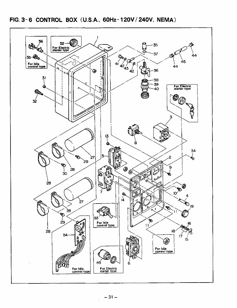
FIG. 3- 6 CONTROL BOX (U.S.A., 6OHz- 120V/ 240V, NEMA)
56
=a ' \
For Idle control type
31 I
28
- 31 -

FIG. 3- 6 CONTROL BOX ( U.S.A., ~OHZ: .~ 2OVI 240V, , . . . . ..
Ref. P a r t s N u m b e r D e s c r i p t i o n P’ t:
No.
1 1 3 89-40650-08 C O N T R O L BOX A S S ’ Y For Idlecontrol t y p e 1 Includes items 2 thru 19, 27 thru 34 and 53 thru 55
* l 3 89-40669-08 C O N T R O L BOX A S S ’ Y 1 For Electric starter type Includes items 2 thru 18, 27 t h r u 34 and 49
* 1 389-40939-08 C O N T R O L BOX A S S ’ Y 1 For Electric starter t y p e w i t h Idle control Includes items 2 thru 18, 27 thru 34, 49 and 53 t h ru 55
1 389-43093-08 C O N T R O L BOX For Idle control type 1
1 389-43092-08 C O N T R O L BOX For Electric starter type 1 * 2 389-41476-08 C O N T R O L P A N E L A A S S ’ Y 1
For Idle control type Includes itetas 3 thru 19 and 53
* 2 389-41496-08 C O N T R O L P A N E L A ASS’ Y 1 For Electric starter type Includes items 3 thru 18 and 49
- 32 -

FIG. 3- 6 CONTROL BOX (U.S.A.. 6OHz- 120V/ 240V, NEMA)
r
38 39 40
I i
J I 6
44
For Electric starter type
J
- 33 -

FIG. 3- 6 CONTROL BOX (USA., 60Hz- 120V/240V, NEMA) .~ - .
Interchangeability
No. Ref .'
P a r t s N u m b e r Execution D e s c r i p t i o n
389-59990-08
6 S C R E W 353-49904-08 2 T E R M I N A L ' t e s t e r 391-47500-03 1 N U T
1 F U E L S T R A I N E R A S S ' Y 064-20023-10 1 NUT, j o i n t 053-30900-20
Includes items 37 thru 42 064-20003-30
1 P A C K I N G 0 6 4 - 2 0 0 0 2 - 3 0 1 F I L T E R 064-20002-20 1 '0" R I N G
1 4 0 1 0 6 4 - 2 0 0 0 2 - 1 0 ] CUP 41 42
064-2-0002-40
344-45615-08 53 374-47540-08 52 066-00001-1 1 49 085-10600-00 45 056-11100-20 44 052-10700-42 43 064-20002-50
B A N J O B O L T ~~
1 F I B E R P A C K I N G
1 B A N J O 2
1 S W I T C H A S S ' Y For Idle control type 1 G R O M M E T For Electric starter type 1 K E Y S W I TCH ASS' Y For Electric starter type
1 R U B B E R PIPE (64IX124IX190mm) 2 H O S E C L A M P
1 5 4 1 3 8 8 - ~ - 3 0 6 ~ 0 3 - 0 8 ~ 1 - I D L E C O N T R O L U N ~ I T ForIdlewntrol tm I 11 ~~
55 004-35041-00 S C R E W a n d W A S H E R A S S ' Y For Idle control type
1 5 6 1 363-56000-08 I C O R D B U S H For Idle control type I 1 I t-
E I I I I I , I When ordering parts ; Always give the Hodel, Specification and Serial Number of Generator.
- 34 -
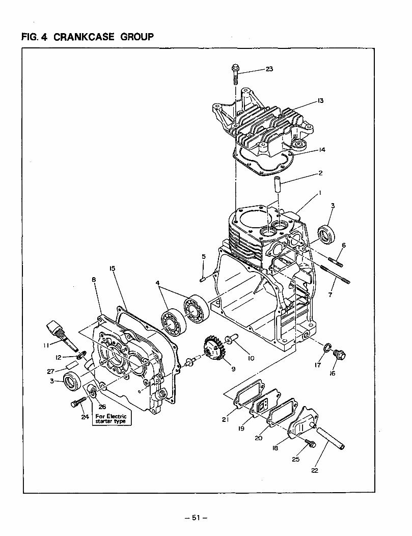
FIG. 4 CRANKCASE GROUP
25 / 22

FIG. 4 CRANKCASE GROUP Interchangeability -
Ref. No.
P a r t s N u m b e r D e s c r i p t i o n P' ty Execution
- 52 -

FIG. 5 CRANK and PISTON GROUP
I
- 53 -
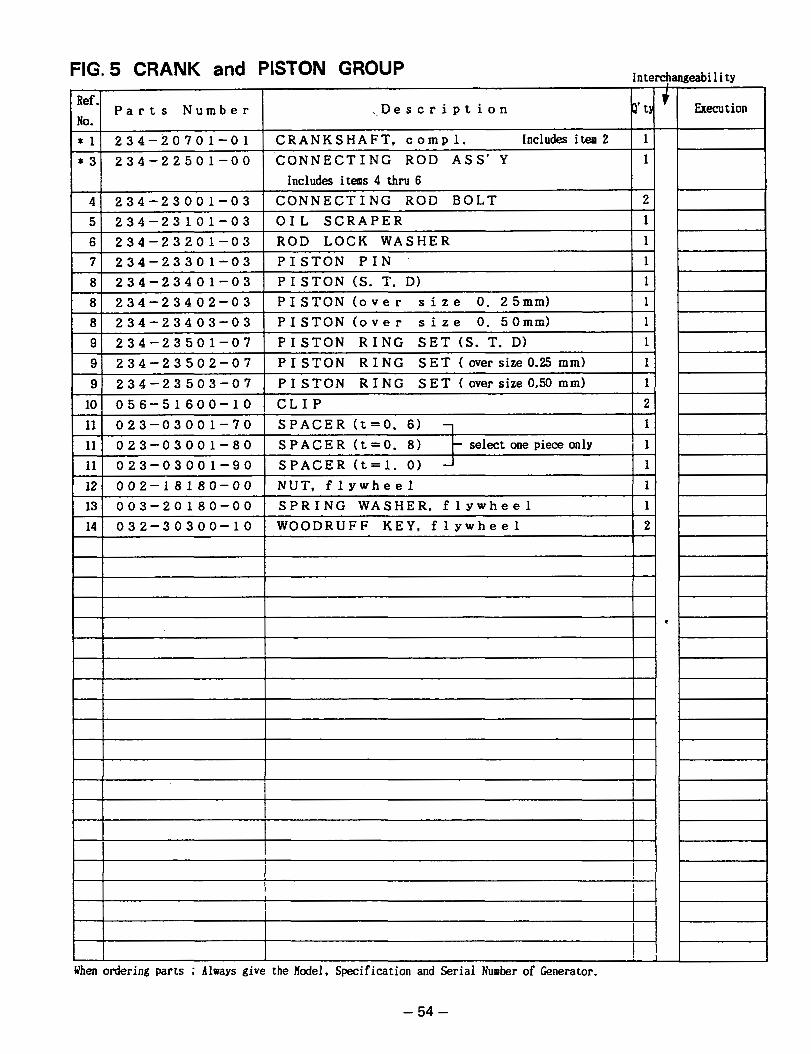
J
FIG. 5 CRANK and PISTON GROUP Interchangeability
I
i 1 I I
I I
i I
- 54 -

FIG. 6 INTAKE and EXHAUST GROUP
i
- 55 -
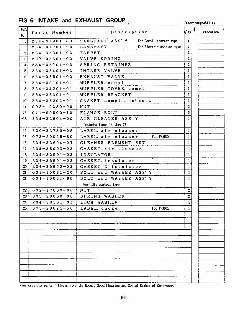
FIG. 6 INTAKE and EXHAUST GROUP Interchangeability
Ref-l No. Part s Numb e r D e s c r i p t i o n
i
1 2 3 4 - 3 1 9 0 1 - 0 0 CAMSHAFT ASS'Y For Recoil starter type 1 i 1 1 2 3 4 - 3 1 7 0 1 - 0 3 CAMSHAFT For Electric starter type 1
~~
2 ) 2 3 4 - 3 3 3 0 1 - 0 3 I TAPPET I 2 1 31 2 2 7 - 3 3 6 0 1 - 0 3 I VALVE SPRING I 21
4 1 2 3 4 - 3 3 7 0 1 - 0 3 I SPRING RETAINER I 21 51 2 3 4 - 3 3 4 0 1 - 0 3 I INTAKE VALVE I 11
61 2 3 4 - 3 3 5 0 1 - 0 3 I EXHAUST VALVE I 11
71 2 3 4 - 3 0 1 0 1 - 0 1 I MUFFLER. com~l. I 11
81 2 3 4 - 3 4 2 0 1 - 0 1 I MUFFLER COVER. c o m ~ l . I 11
91 2 3 4 - 3 5 3 0 1 - 0 1 I MUFFLER BRACKET I 11
101 2 3 4 - 3 5 2 0 2 - 0 1 I GASKET. com~l.. e x h a u s t I 11
11' 0 0 2 - 1 9 0 8 0 - 0 0 NUT , 2 12 0 1 1 - 0 0 6 0 0 - 1 0 FLANGE BOLT 5
*13 2 3 4 - 3 2 6 0 4 - 0 0 AIR CLEANER ASS' Y 1
Includes i t e m 14 thru 17 15 2 2 0 - 3 2 7 3 0 - 0 8 LABEL,air c l e a n e r 1
15 0 7 3 - 2 0 0 2 5 - 8 0 LABEL,air c l e a n e r For FRANCE 1 16 2 3 4 - 3 2 6 0 4 - 0 7 CLEANER ELEMENT SET 1
17 2 3 4 - 3 6 0 0 3 - 0 3 GASKET,air c l e a n e r 1
18 2 3 4 - 3 2 9 0 1 - 0 3 INSULATOR 1
19 2 3 4 - 3 5 9 0 1 - 0 3 GASKET, i n s u l a t o r 1
20 2 3 4 - 3 5 9 0 2 - 0 3 GASKET 2. i n s u l a t o r 1 21 0 0 1 - 1 0 0 6 1 - 2 0 BOLT a n d WASHER ASS'Y 1
21 I 0 0 1 - 1 0 0 6 1 - 6 0 BOLT a n d WASHER ASS'Y I For Idle control type I lI
221 0 0 2 - 1 7 0 6 0 - 0 0 1 NUT I 2 1
2 3 1 0 0 3 - 2 0 0 6 0 - 0 0 I SPRING WASHER I 2 1
241 2 3 4 - 3 6 5 0 1 - 0 1 I LOCK WASHER I 11
2 5 1 0 7 3 - 2 0 0 2 5 - 5 0 LABEL,choke For FRANCE 1
I
1
! I
! I
I I
1
F-
- 56 -
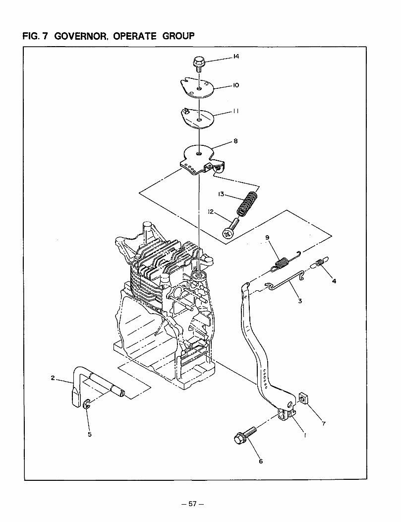
FIG. 7 GOVERNOR, OPERATE GROUP
2
6
- 57 -

. . ." . . . .. . . -
. .
FIG. 7 GOVERNOR. OPERATE GROUP 1 nterchanneabi 1 i ty
P a r t s N u m b e r D e s c r i p t i o n
13) 220-48001-01 C O N T R O L S P R I N G 1
1 4 ) 011-00600-30 F L A N G E BOLT 1
When ordering parts ; Always give the Hcdel, Specification and Serial !Cumber of Generator.
- 58 -

FIG. 8 COOLING and STARTING GROUP 1
7 3
- 59 -

. _.. I
FIG. 8 COOLING and STARTING GROUP Interchangeability r Execution
- Ref, No. * 1 -
- * 1
D e s c r i p t i o n Jp't P a r t s N u m b e r I
234-51256-01 1 BLOWER HOUSING, c o m p l . For Recoil starter type Includes items 2 and 19
234-51556-01 1 BLOWER HOUSING, c o m p l . For U.S.A., Recoil starter type Includes items 2 and 19
234-51401-01 1 BLOWER HOUSING, c o m p l . For Electric starter type Includes items 2 and 19
234-51557-01
Includes i tests 2 and 19 For U.S.A., Electric starter type
1 BLOWER HOUSING,compl.
234-91701-03 1 L A B E L , t r a d e m a r k 234-91'751-03 1 LABEL, t r a d e m a r k
For U.S.A., Recoil starter type ( Not for sale 234-91752-03 1 LABEL, t r a d e m a r k
For U.S.A., Electric starter type ( Not for sale 011-00600-20 13 FLANGE BOLT
* 1
* l
2
2
- 2
- 3 4 5
- - 234-52601-03
1 HEAD COVER 234-52801-13 1 CYLINDER BAFFLE
* 6 l 1 234-50211-00 RECOIL STARTER ASS'Y Includes items 7 thru 17
7 106-50116-08 1 REEL. c o m D l . 207-50122-18 1 SPIRAL SPRING
8 9 106-50113-08
106-50144-08 1 FRICTION PLATE I 1
1 106-50136-08 j RETURN SPRING 1 FRICTION SPRING 106-50132-08 2 RATCHET 106-50128-18 1 HANDLE 206-50101-08 1 ROPE
10 11 12 13
14
- - -
15 16
17
- -
106-50185-08 / THRUST WASHER I 1
F 106-50186-08 I CLIP I 1
234-50145-08 I STARTING PULLEY I 1
18 011-00600-10 I FLANGE BOLT 1 4
19 073-20035-50 I LABEL, s t o p s w i t c h I 1
20 073-20025-70 I LABEL, s t a r t For FRANCE I 1
! I I
I I
Gjhen ordering. parts ; Always give the Hodel, Specification and Serial
-60-
Number of Generator.

FIG. 9 FUEL. LUBRICANT GROUP
For Idle control type
I I
J
DETA I L "A"
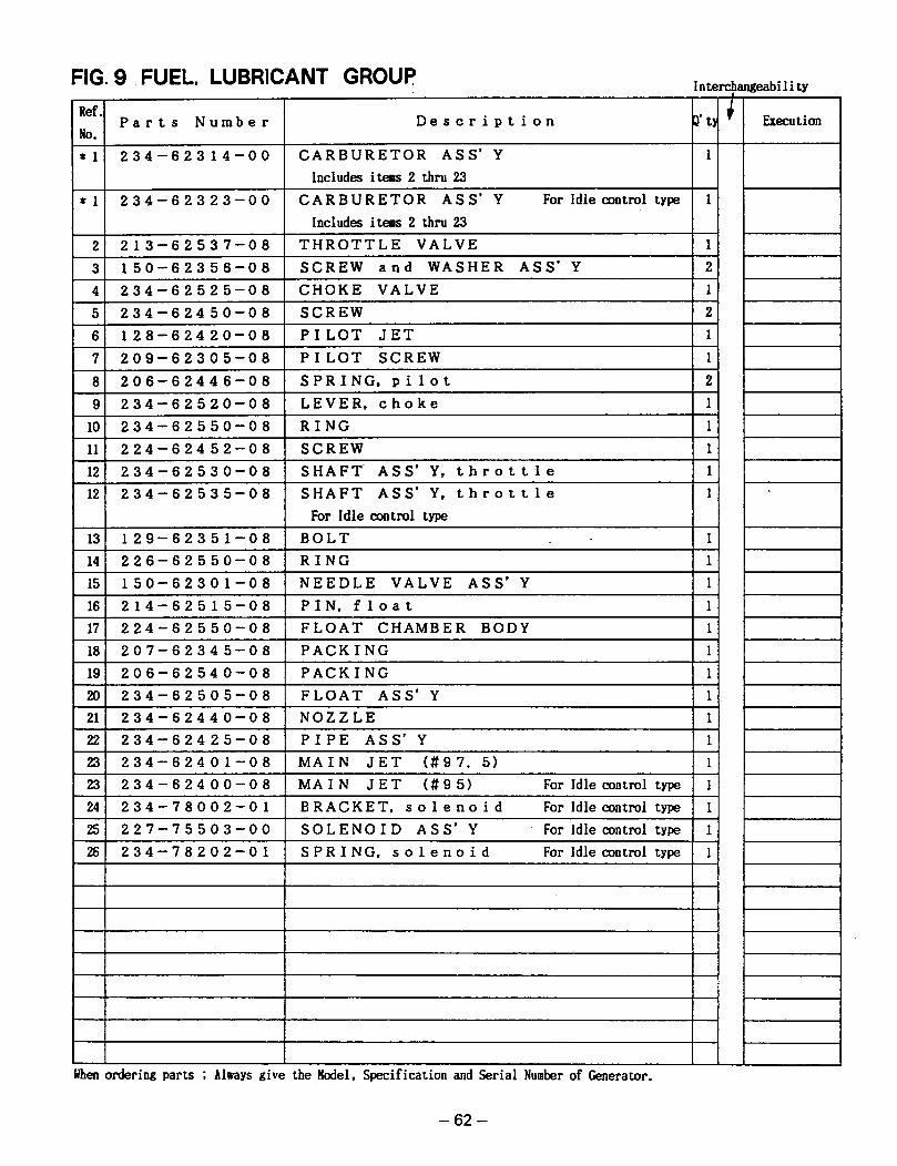
1 * 1 1 2 3 4 - 6 2 3 1 4 - 0 0
2 2 1 3 - 6 2 5 3 7 - 0 8
3 1 5 0 - 6 2 3 5 6 - 0 8
4 2 3 4 - 6 2 5 2 5 - 0 8
5 2 3 4 - 6 2 4 5 0 - 0 8
6 1 2 8 - 6 2 4 2 0 - 0 8
7 2 0 9 - 6 2 3 0 5 - 0 8
8 2 0 6 - 6 2 4 4 6 - 0 8
9 2 3 4 - 6 2 5 2 0 - 0 8
10 2 3 4 - 6 2 5 5 0 - 0 8
11 2 2 4 - 6 2 4 5 2 - 0 8
12 2 3 4 - 6 2 5 3 0 - 0 8
12 2 3 4 - 6 2 5 3 5 - 0 8
1 1 3 1 1 2 9 - 6 2 3 5 1 - 0 8
I 141 2 2 6 - 6 2 5 5 0 - 0 8
1 1 5 1 1 5 0 - 6 2 3 0 1 - 0 8
FIG. 9 FUEL, LUBRICANT GROUP interchangeabi 1 i ty
uben ordering parts ; Always give the Hodel, Specification and Serial Nuaber of Generator.
1 1 6 1 2 1 4 - 6 2 5 1 5 - 0 8
I 171 2 2 4 - 6 2 5 5 0 - 0 8
18 2 0 7 - 6 2 3 4 5 - 0 8
19 2 0 6 - 6 2 5 4 0 - 0 8
20 2 3 4 - 6 2 5 0 5 - 0 8
22 2 3 4 - 6 2 4 2 5 - 0 8
1 2 3 1 2 3 4 - 6 2 4 0 1 - 0 8
1 2 3 ) 2 3 4 - 6 2 4 0 0 - 0 8
1 2 4 1 2 3 4 - 7 8 0 0 2 - 0 1
1 2 5 1 2 2 7 - 7 5 5 0 3 - 0 0
1 2 6 1 2 3 4 - 7 8 2 0 2 - 0 1
CARBURETOR ASS' Y Includes items 2 thru 23
CARBURETOR ASS' Y For idle control type Includes iteas 2 thru 23
THROTTLE VALVE SCREW a n d WASHER ASS' Y CHOKE VALVE SCREW PILOT JET PI LOT SCREW SPRING, p i l o t LEVER. c h o k e RING SCREW SHAFT. ASS' Y, t h r o t t l e SHAFT ASS' Y, t h r o t t l e For Idle control type BOLT . .
RING NEEDLE VALVE A S S ' Y PIN, f l o a t FLOAT CHAMBER BODY PACKING PACKING FLOAT ASS' Y NOZZLE PIPE ASS' Y MAIN JET ( # 9 7 . 5) MAIN JET ( # 9 5 ) For Idle control type BRACKET. s o l e n o i d For Idle control type
SOLENOID ASS' Y For Idle control type
SPRING, s o l e n o i d For Idle control type
- 62 -
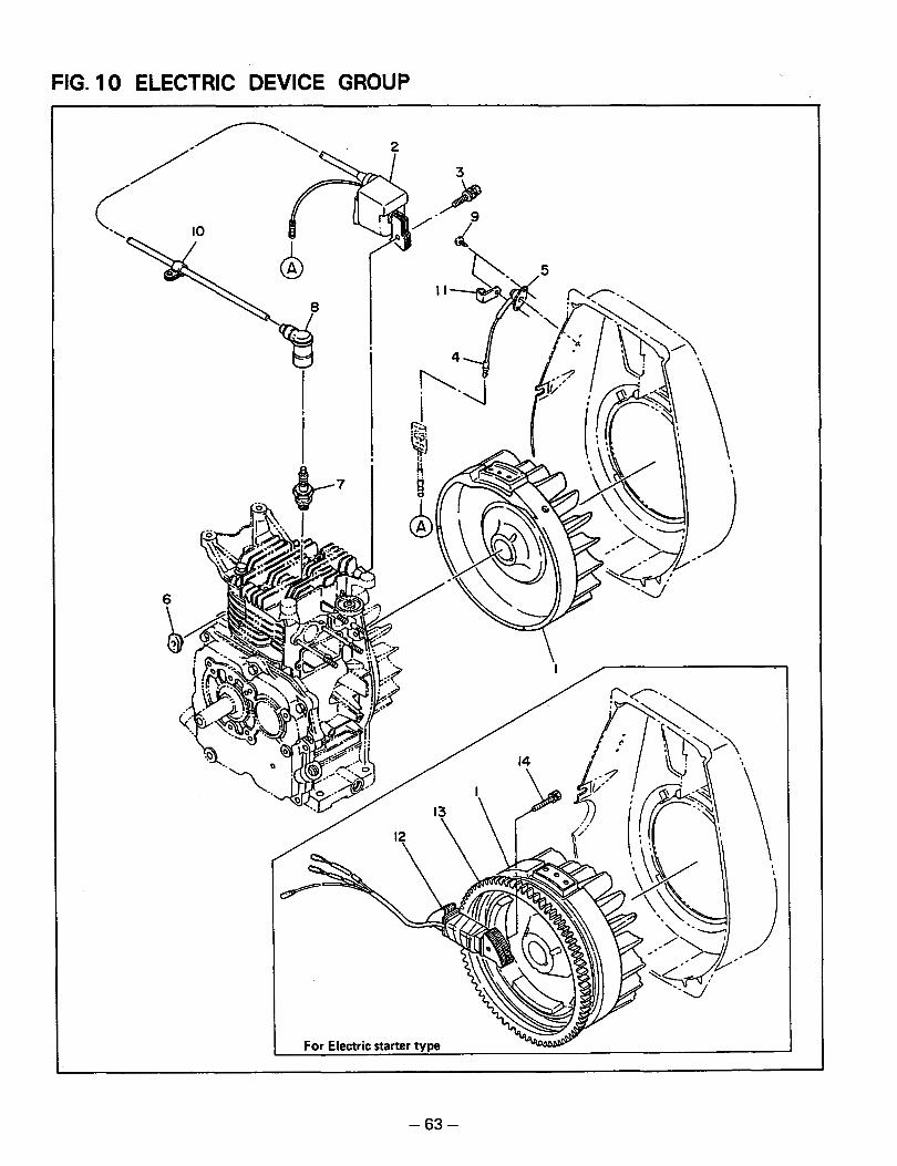
FIG. 10 ELECTRIC DEVICE GROUP
- 63 -

.~..... .. .
FIG. 10 ELECTRIC DEVICE GROUP Intercbanneabilitv
Ref. P a r t s N u m b e r D e s c r i p t i o n
no. 2 3 4 - 7 0 2 0 1 - 0 0 M A G N E T O A S S ' Y For Recoil starter type 1
13 234-71002-03 R I N G G E A R For Electric starter type 1
14 001-17062-50 B O L T a n d W A S H E R A S S 'Y 2 For Electric starter type
When ordering parts ; Always give the Hodel, Specification and Serial Number of Generator.
- 64 -

FIG. 11 OIL SENSOR GROUP
'\
6
- 65 -
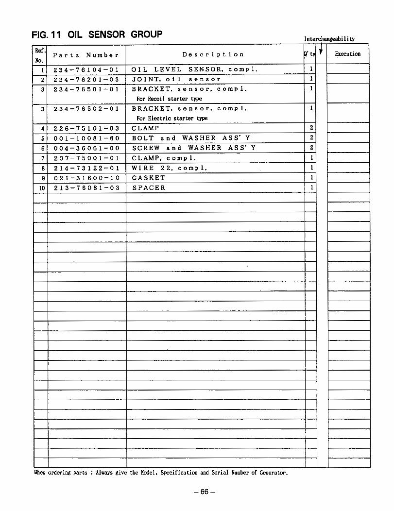
a
8
1 234-76104-01 OIL LEVEL SENSOR, compl. 1 2 234-76201-03 J O I N T , o i l s e n s o r 1 3 234-76501-01 BRACKET, sensor, compl. 1
For Recoil starter type 3 234-76502-01 BRACKET, sensor, compl. 1
For Electric starter type 4 226-75101-03 C L A M P 2 5 001-10081-60 B O L T and W A S H E R ASS'Y 2
I 61 004-36061-00 I S C R E W a n d W A S H E R ASS'Y I 21 7 207-75001-01 CLAMP. compl. 1 8 214-73122-01 W I R E 22, compl. 1
1-~9l 021-31600-10 I G A S K E T I 11
1101 213-76081-03 I S P A C E R I 11
FIG. 11 OIL SENSOR GROUP Interchangeability
P a r t s N u m b e r
1 I I ordering parts ; Always give the Model, Specification and Serial Number of Generator.
- 66 -

FIG. 12 STARTING MOTOR GROUP (ELECTRIC STARTER PARTS)
18
.n.
- 67 -
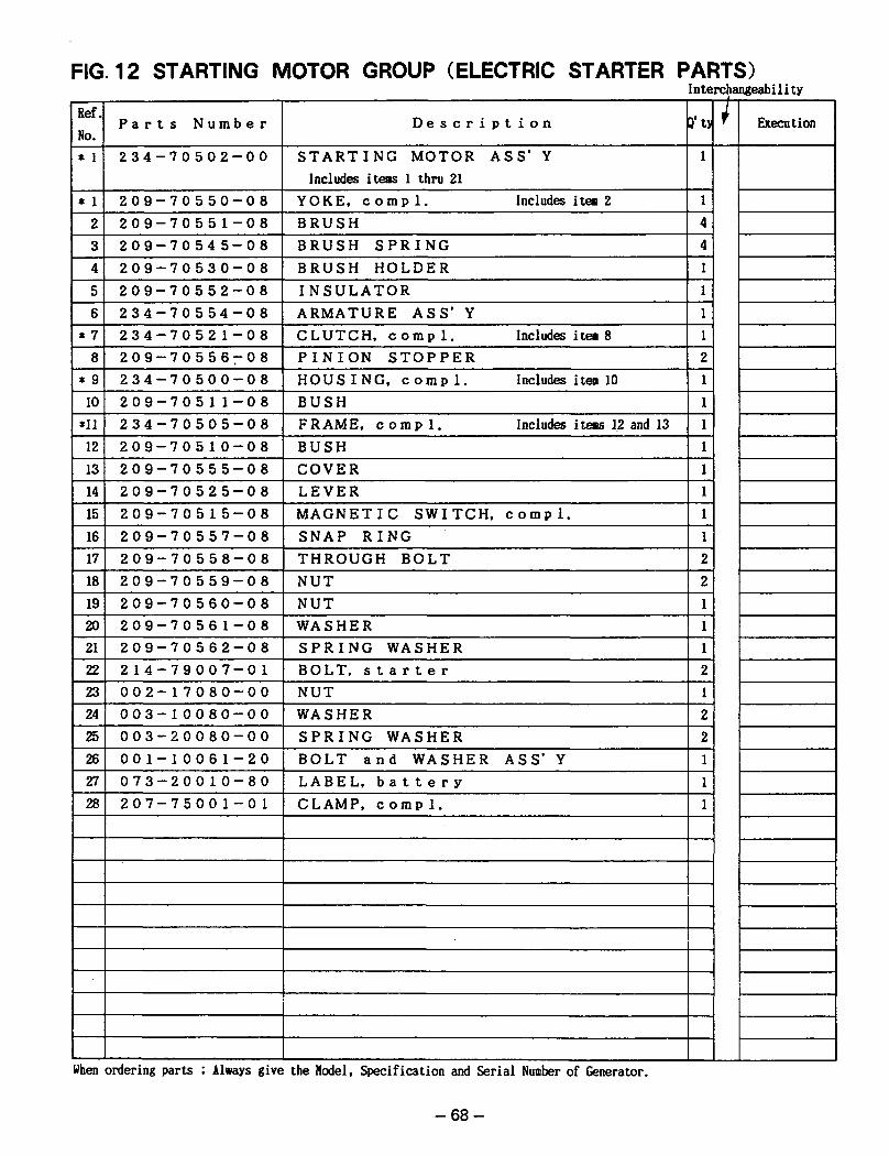
FIG. 12 STARTING MOTOR GROUP (ELECTRIC STARTER PARTS)
Ref. P a r t s N u m b e r
NO *
* 1 234-70502-00
* 1 2
209-70550-08
4 209-70545-08 3 209-70551-08
234-70554-08 6 209-70552-08 5 209-70530-08
* 7 234-70521-08 8 209-70556708
*9 234-70500-08 IO 209-7051 1-08
*11 2 34-70505-08 12 209-70510-08 13 14
209-70555-08
207-75001-01 28 073-20010-80 27 001-10061-20 26 003-20080-00 25 003-10080-00 24 002-17080-00 23 214-79007-01 22 209-70562-08 21 209-70561-08 20 209-70560-08 19 209-70559-08 18 209-70558-08 17 209-70557-08 16 209-70515-08 15 209-70525-08
When ordering parts Always
Interchangeability
D e s c r i p t i o n 3 ' t y Execution 1 1 1
S T A R T I N G M O T O R A S S ' Y
N U T 1 W A S H E R 2 S P R I N G W A S H E R 2 BOLT a n d W A S H E R A S S ' Y 1 LABEL, b a t t e r y 1 C L A M P , c o m p l . 1
I
i
flodel, Specification and Serial Number of Generator.
- 68 -

FIG. 14 WHEEL. HANDLE and HANGER
8
- 7 1 -
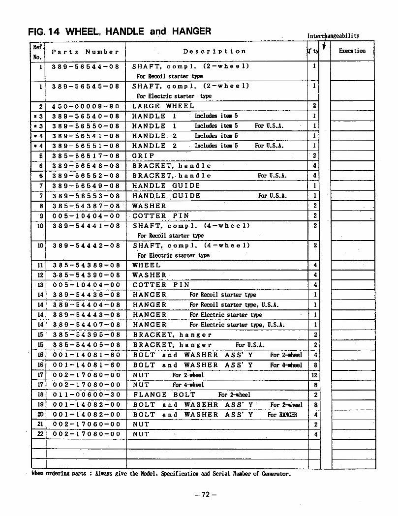
FIG. 14 WHEEL, HANDLE and HANGER In terchangeabi 1 i ty
1
I
Ref. NO.
P a r t s N u m b e r D e s c r i p t i o n P’tY + Execution
1 3 8 9 - 5 6 5 4 . 4 - 0 8 S H A F T , c o m p l . ( 2 - w h e e l ) 1 For Recoil starter type
1 3 8 9 - 5 6 5 4 5 - 0 8 SHAFT, c o m p l . ( 2 - w h e e l ) 1 For Electric starter type
2 4 5 0 - 0 0 0 0 9 - 9 0 L A R G E W H E E L 2 * 3 3 8 9 - 5 6 5 4 . 0 - 0 8 H A N D L I E 1 ~ Includesitem5 1 * 3 3 8 9 - 5 6 5 5 0 - 0 8 H A N D L E 1 Includes item 5 For U.5.d. 1
For Recoil starter t
Jhen ordering parts ; Always give the Hodel, Specification and Serial Number of Generator.
- 7 2 -


Robin America, Inc. 940 Lively Blvd. Wood Dole, I t 60191 Phone: 630-350-8200 Fox: 630-350-8212 e-mail: sales @robinamerica.com www.robinamerica.com PRINTED IN THE USA