rf point level control with sensor monitor gi924 · rf point level control with sensor monitor...
TRANSCRIPT
Form 924 (05.18) ©SOR Inc. 1/16
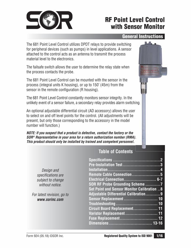
The 681 Point Level Control utilizes DPDT relays to provide switching for peripheral devices (such as pumps) in level applications. A sensor attached to the control acts as an antenna to transmit the process material level to the electronics.
The failsafe switch allows the user to determine the relay state when the process contacts the probe.
The 681 Point Level Control can be mounted with the sensor in the process (integral units K housing), or up to 150’ (45m) from the sensor in the remote configuration (R housing).
The 681 Point Level Control constantly monitors sensor integrity. In the unlikely event of a sensor failure, a secondary relay provides alarm switching.
An optional adjustable differential circuit (AD accessory) allows the user to select on and off level points for the control. (All adjustments will be present, but only those corresponding to the accessory in the model number will function.)
RF Point Level Control with Sensor Monitor
General Instructions
Registered Quality System to ISO 9001
Design and specifications are subject to change
without notice.
For latest revision, go to www.sorinc.com
NOTE: If you suspect that a product is defective, contact the factory or the
SOR® Representative in your area for a return authorization number (RMA).
This product should only be installed by trained and competent personnel.
Table of Contents Specifi cations ...................................2
Pre-Installation Test ............................3
Installation .......................................4
Remote Cable Connection .....................5
Electrical Connection ........................ 6-7
SOR RF Probe Grounding Scheme ...........7
Set Point and Sensor Monitor Calibration ..8
Adjustable Differential Calibration ...........9
Sensor Replacement ......................... 10
Troubleshooting ............................... 10
Circuit Board Replacement .................. 11
Varistor Replacement ........................ 11
Fuse Replacement ............................ 12
Dimensions ................................ 13-16
ing.
.
2/16 Form 924 (05.18) ©SOR Inc.
Specifi cations
Ambient temperature limits ..............................................................................-40 to 160oF/-40 to 71oC
EnclosureWeatherproof .............................................................................................NEMA 4, 4X, IP65Explosion proof .....................................................................................Class I, Group C & D; Class II, Group E, F, & G; Class III; Divisons 1 & 2Supply voltage ..................................................................................................... See page 8DPDT relay contact rating .........................................................................10 Amps 250 VAC
10 Amp 30 VDC (resistive)Remote distance from sensor ............................................................................... 150’/45mAdjustment rangeRange I ...........................................................................................0 - 300pf, .5pF sensitivityRange II .....................................................................................300 - 1000pf, 1pF sensitivitySet point stabilityRange I .............................................................................................0.075 pF/oF (0.13 pF/oC)Range II ..............................................................................................0.15 pF/oF (0.27 pF/oC)Zero rangeablility ......................................................................................................1000pFRepeatability ................................................................................................................ 0.5%Adjustable differential range ................................................................................ 0 - 1000pFResponse time .................................................................................................. <100 msecPower at sensor ............................................................................................... <10 μ joulesElectrostatic discharge (ESD) protectionIEC 1000-4-2 compatibleElectrical conduit connection .............................................................................3/4” NPT(F)
Form 924 (05.18) ©SOR Inc. 3/16
Pre-Installation Test
Remove instrument from shipping box and visually inspect for obvious physical dam-age. Report any shipping damage to the carrier. Report any internal discrepancies to the factory representative in your area. Record the serial number from the nameplate should conversation with the factory be necessary.
Remove housing cover. Place instrument on an insulated surface or support so sensor does not touch a conductive surface. Ensure area is safe and observe normal precautions for exposed and powered electronic components. Apply appropriate power to terminals of Line Power Terminal Block. (See page 6.)
Move failsafe select switch to LO position and observe green LVL LED. (See ). Turn the Level adjustment clockwise (25 turns) to decrease the set point until the
green LVL LED turns on.
NOTE: Do not turn the Level adjustment past 25 turns! Damage to the unit could result.
Turn the LEVEL adjustment counterclockwise until the green LED turns off. Slowly move a hand toward the probe to touch it. The green LED will be on when the
probe is touched. If not, turn the LEVEL adjustment clockwise less than one turn. The green LED should be on when the probe is touched.
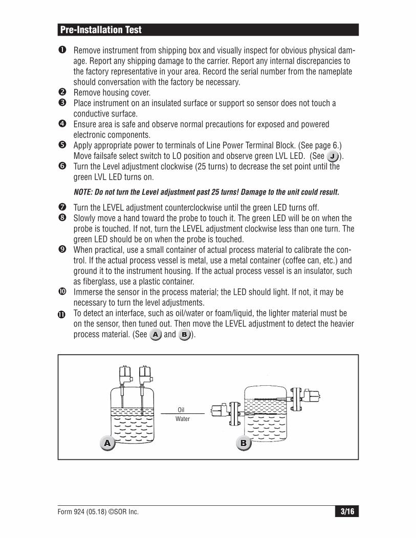
When practical, use a small container of actual process material to calibrate the con-trol. If the actual process vessel is metal, use a metal container (coffee can, etc.) and ground it to the instrument housing. If the actual process vessel is an insulator, such as fiberglass, use a plastic container.
Immerse the sensor in the process material; the LED should light. If not, it may be necessary to turn the level adjustments.
To detect an interface, such as oil/water or foam/liquid, the lighter material must be on the sensor, then tuned out. Then move the LEVEL adjustment to detect the heavier process material. (See and ).
OilWater

4/16 Form 924 (05.18) ©SOR Inc.
Conduit must be installed between the sensor base and the electronics housing to provide a raceway for sensor extension cables. (See ).
If the sensor is a solid rod it may be cut or bent for clearance or placement. Use a 3-inch radius should a bend be required. It is permissible to increase the sensor length by welding a length of identical rod to the supplied sensor. Re-calibration is required if the probe length is changed.
Installation
Standard Confi guration is a 3/4” NPT(M) pipe nipple that threads into a 3/4” NPT(F) vessel nozzle or half coupling. Allow a 4-inch turn radius. (See and ). Open tanks, vats, sumps or basins may require a locally-made bracket mount similar to that shown in .
Optional Confi guration is a raised face or flat face ANSI flange. See Form 1100 for selection. (See and ).
Orientation The control can be mounted in any position. Placement and orientation of the sensor in a vessel is usually determined by available nozzles. The sensor should be away from fill points to avoid false trips. The insulator bushing on the sensor should protrude a minimum of 1” from the inner wall of the vessel. The sensor must not touch any metal, nor should conductive process build-up be allowed to bridge between the sensor and a grounded metal tank wall.
This product must be installed with an explosion proof breather vent
per Agency requirements and the National Electrical Code-Article 501,
Section F, paragraph 3.

Form 924 (05.18) ©SOR Inc. 5/16
Remote Cable Connection
Electical power must be disconnected from explosion proof models before
the cover is removed. Failure to do so could result in severe personal injury
or substantial property damage.
Ensure that wiring conforms to all applicable local and national electrical codes and install unit(s) according to relevant national and local safety codes.
Fishing the Sensor Extension Cables
One three-conductor extension cable is required. Pull cable from the sensor base so that the free ends follow the fish through the conduit. (See ).
Connections Inside Sensor Base
Inside the sensor base, a remote circuit board rests in a plastic holder. Attach the cable wires to the terminal block on the circuit board as follows:
Connections Inside Electronics Housing
Inside the electronics housing, unscrew the bracket holding the circuit board in place. Pull the board out of the holder. At the bottom of the circuit board, there is a connector labeled “+ - probe”. Attach the cable wires to the terminal block as shown above.
Conduit must be installed between the sensor base and the electronics housing to provide a raceway for sensor extension cables. (See ).
Terminal Block Cable
+ red wire - black wire
PROBE white wire
Control BoardTerminal Block
Remote BoardTerminal Block
Conduit must meet Class I Group C & D;Class ll Groups E, F & G; Division 1 & 2
Electronics Housing
Remote Sensor Board
Probe Connector
Sensor Base
Control Board
6/16 Form 924 (05.18) ©SOR Inc.
Electrical Connection
Level and Alarm (See ). DPDT relays: 10 amp 250 VAC; 10 amp 30 VDC (resistive)Connect external circuit wires as required to screw clamp terminals marked: C1 (Common) C2 (Common) NO1 (Normally Open) NO2 (Normally Open) NC1 (Normally Closed) NC2 (Normally Closed)
Line Power Voltage Limits Max. Current Draw Board Marking(See ). 12 ± 10% VDC 100 mA + – 24 ± 10% VDC 100 mA + – 120 (95-130) VAC 25 mA L1, N (shown) 240 (195-250) VAC 13 mA L1, L2
Ensure that wiring conforms to all applicable local and national electrical codes and install unit(s) according to relevant national and local safety codes.
Electrical power must be disconnected from explosion proof models before
the cover is removed. Failure to do so could result in severe personal injury
or substatnial property damage.
1. Remove housing cover.2. Observe applicable electrical codes and recognized wiring practices.3. Remove two mounting screws and slide out PC board to expose green ground screw (Internal Primary Equipment Ground/Earth) in base of housing.4. Connect green line ground wire to green ground screw on base of housing. (Ground wire should be a minimum of 18-AWG.)5. Reposition PC board, replace and tighten mounting screws. Ensure that banana plug on sensor lead wire is secure in sensor jack.6. Connect hot line power wire (typically black) to L1 position on the terminal block.7. Connect neutral line power wire (typically white) to N position on the terminal block.8. Replace cover.9. Apply power as desired.
1. Perform Steps 1 through 6 above.2. Connect second hot line power wire (typically red) to L2 position on the terminal block.3. Replace cover.4. Apply power as desired. 1. Perform Steps 1 through 5 above if a case or equipment ground wire is provided for connection to earth ground.2. Connect positive line power wire to the terminal marked (+).3. Connect negative line power wire to the terminal marked (–).4. Replace cover.5. Apply power as desired.
120 VAC
(681K7)
240 VAC
(681K8)
12 VDC
(681K5) 24 VDC
(681K6)

Form 924 (05.18) ©SOR Inc. 7/16
SOR RF Probe Grounding Scheme
SOR RF Probe Grounding Scheme
Critical Grounding Path =
CircuitBoard
Line
Neutral
Ground
Electronics Housing
Power Supply
Line
Neutral
Ground
ProcessConnection
SOR Supplied Stilling Well (optional)
Probe Center Conductive Element
IMPORTANT! Do notprovide separate earth grounding for the process connection. This can create a parallel grounding circuit that will impair operation and calibration.
Green LVL LED Alarm Relay Terminal Blocks
Failsafe Switch
Level Relay Terminal Blocks
Line Power Terminal BlockRed LED
Yellow LED
Adjustable Differntial Adjustments (Function only on units with AD accessory)
Remote Probe Terminal Block (Remote units only)
Do not provide separate earth grounding
for the process connection. This can
create a parallel grounding circuit
that will impair operation and calibration.
8/16 Form 924 (05.18) ©SOR Inc.
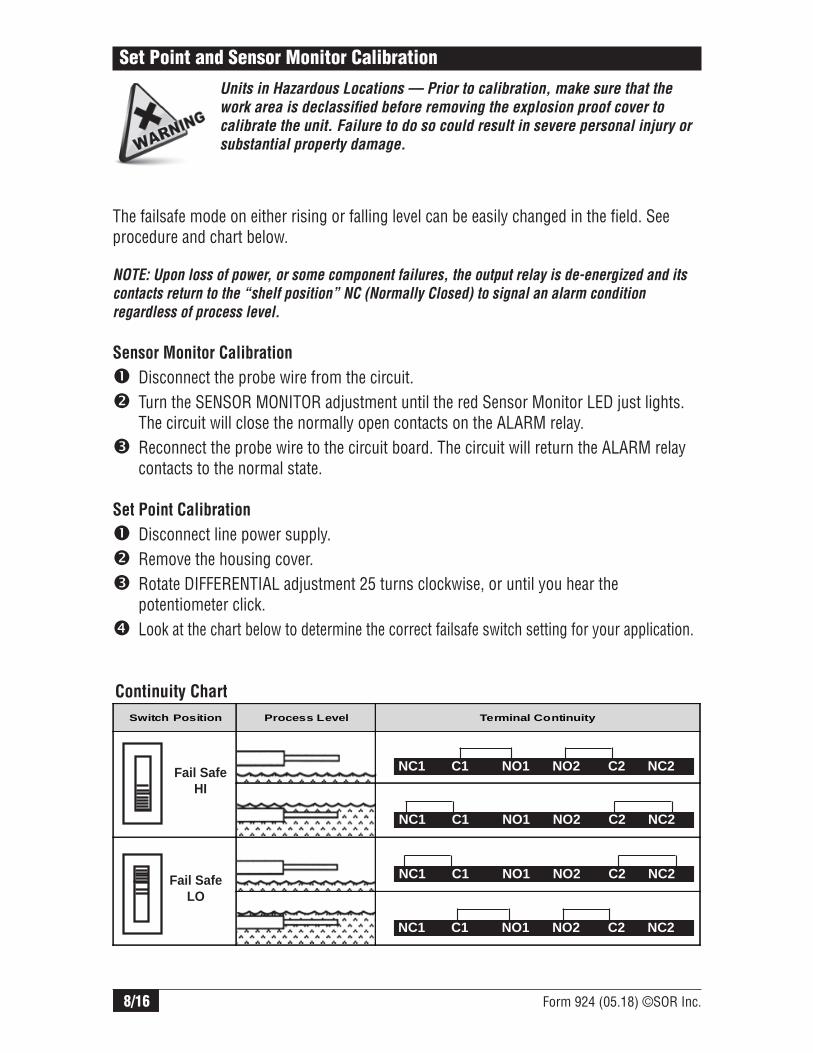
Set Point and Sensor Monitor Calibration
The failsafe mode on either rising or falling level can be easily changed in the field. See procedure and chart below.
NOTE: Upon loss of power, or some component failures, the output relay is de-energized and its
contacts return to the “shelf position” NC (Normally Closed) to signal an alarm condition
regardless of process level.
Sensor Monitor Calibration
Disconnect the probe wire from the circuit. Turn the SENSOR MONITOR adjustment until the red Sensor Monitor LED just lights. The circuit will close the normally open contacts on the ALARM relay. Reconnect the probe wire to the circuit board. The circuit will return the ALARM relay contacts to the normal state.
Set Point Calibration
Disconnect line power supply. Remove the housing cover. Rotate DIFFERENTIAL adjustment 25 turns clockwise, or until you hear the potentiometer click. Look at the chart below to determine the correct failsafe switch setting for your application.
Units in Hazardous Locations — Prior to calibration, make sure that the
work area is declassifi ed before removing the explosion proof cover to
calibrate the unit. Failure to do so could result in severe personal injury or
substantial property damage.
Continuity Chart
Fail SafeHI
Fail Safe LO
NC1 C1 NO1 NO2 C2 NC2
NC1 C1 NO1 NO2 C2 NC2
NC1 C1 NO1 NO2 C2 NC2
NC1 C1 NO1 NO2 C2 NC2
Switch Position Process Level Terminal Continuity
Form 924 (05.18) ©SOR Inc. 9/16
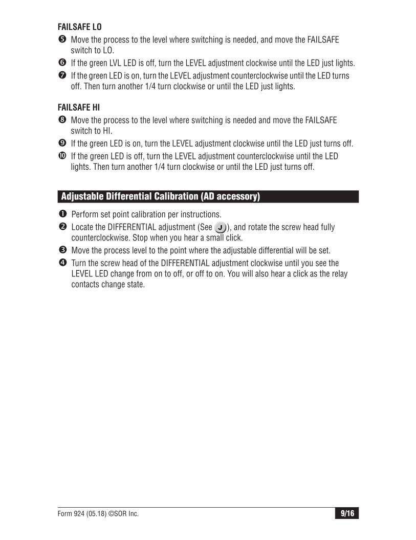
Perform set point calibration per instructions. Locate the DIFFERENTIAL adjustment (See ), and rotate the screw head fully counterclockwise. Stop when you hear a small click. Move the process level to the point where the adjustable differential will be set. Turn the screw head of the DIFFERENTIAL adjustment clockwise until you see the LEVEL LED change from on to off, or off to on. You will also hear a click as the relay contacts change state.
Adjustable Differential Calibration (AD accessory)
FAILSAFE LO
Move the process to the level where switching is needed, and move the FAILSAFE switch to LO. If the green LVL LED is off, turn the LEVEL adjustment clockwise until the LED just lights. If the green LED is on, turn the LEVEL adjustment counterclockwise until the LED turns off. Then turn another 1/4 turn clockwise or until the LED just lights.
FAILSAFE HI
Move the process to the level where switching is needed and move the FAILSAFE switch to HI. If the green LED is on, turn the LEVEL adjustment clockwise until the LED just turns off. If the green LED is off, turn the LEVEL adjustment counterclockwise until the LED lights. Then turn another 1/4 turn clockwise or until the LED just turns off.

10/16 Form 924 (05.18) ©SOR Inc.
Sensor Replacement
Disconnect power to the unit. Remove the housing cover. Remove two screws holding bracket to plastic holder. Slide out PC board to expose the sensor connection. Disconnect the sensor wire. Unscrew the sensor from the housing. Apply thread sealant to the male threads of the new sensor. Thread the new sensor into the bottom of the housing. Connect the sensor wire to the “probe” connection on the circuit board. Slide the PC board into the grooves in the plastic ring inside the housing.
Replace the two screws in the circuit board Reconnect power and replace the housing cover.
Replacement Sensors
See Form 1100 RF Catalog for replacement sensor model numbers
Troubleshooting
Symptom/Problem Possible Cause Corrective Action
No LEDS lit
1. Power supply turned off2. Improperly wired line power3. Broken power supply wire4. Blown fuse5. Blown varistor
1. Check power supply source2. check terminal block wiring3. Check wiring integrity4. Replace fuse F15. Replace varistor VR1, VR2 or VR3
LVL LED remains lit at all times
1. Probe wire touched housing or other ground2. Setpoint is at the lowest level
1. Check probe that probe wire is properly attached to the probe2. Turn the LEVEL adjustment counterclockwise and retry
LVL LED operates properly, but relay does not respond
1. Relay contact damage2. Burned or broken circuits
1. Replace circuit board or relay2. Replace circuit board
Process material is not detected
1. Sensitivity is improperly set2. Highly conductive product3. Heavy conductive build-up on the sensor4. Circuit failure
1. Recalibrate per page 6 instructions2. Use sheathed sensor3. Use sheathed sensor and periodically remove the build-up4. Replace circuit board
If corrective action is not effective, please consult the factory.
NOTE: Agency certifi ed units, (FM, CSA, IEC) must be returned to SOR for repairs.

Form 924 (05.18) ©SOR Inc. 11/16
Contact the factory for the correct replacement circuit board (Model number required). Disconnect power to the unit. Remove the housing cover. Remove two screws holding bracket to plastic holder Slide out PC board. Disconnect power wiring, sensor wire, and the ground connection to the housing. Connect the sensor lead from the new board to the probe. Connect ground to the housing. Slide the new board into the control housing. Replace the two screws in the circuit board bracket to the plastic holder. These screw are self-tapping. Do not over–tighten Reconnect power and replace the housing cover.
Circuit Board Replacement
Disconnect power to the unit. Remove the housing cover. Unplug the varistor(s) (RV1, RV2, RV3) located on the opposite side of the circuit board from the wiring terminals. (See
)).
Plug in replacement varistor(s). Replace the housing cover. Re-connect power to the unit.
Use the replacement varistor per the following chart:
Varistor Replacement
Control Model Number
Varistor Part Number Quantity Location
6815 2820-015 1 RV1
6816 2820-015 1 RV1
6817 2820-003 3 RV1, RV2, RV3
6818 2820-004 3 RV1, RV2, RV3

12/16 Form 924 (05.18) ©SOR Inc.
Fuse Replacement (AC units only)
Use replacement fuse part number: 2806-001 1/2A Disconnect power to the unit. Remove the housing cover. Unplug the fuse (F1) from the circuit board (See ). The fuse is located on the opposite side of the circuit board from the wiring terminals. Plug in replacement fuse. Replace the housing cover. Reconnect power to the unit.
Reverse Side of Printed Circuit Board
Relays
TransformerLocation
RV1
F1
(120VAC and 240VAC only)
RV2
RV3

Form 924 (05.18) ©SOR Inc. 13/16
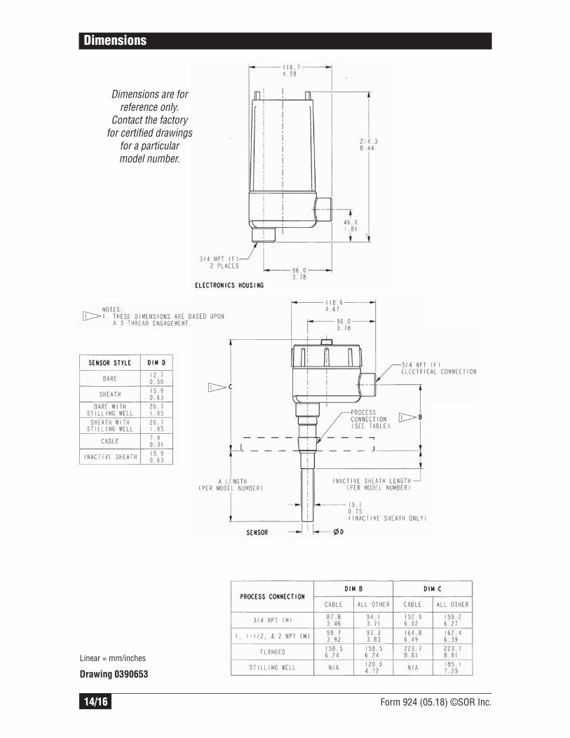
Dimensions
Dimensions are for reference only.Contact the factory
for certified drawings for a particular model number.
Linear = mm/inches
Drawing 0390654
14/16 Form 924 (05.18) ©SOR Inc.
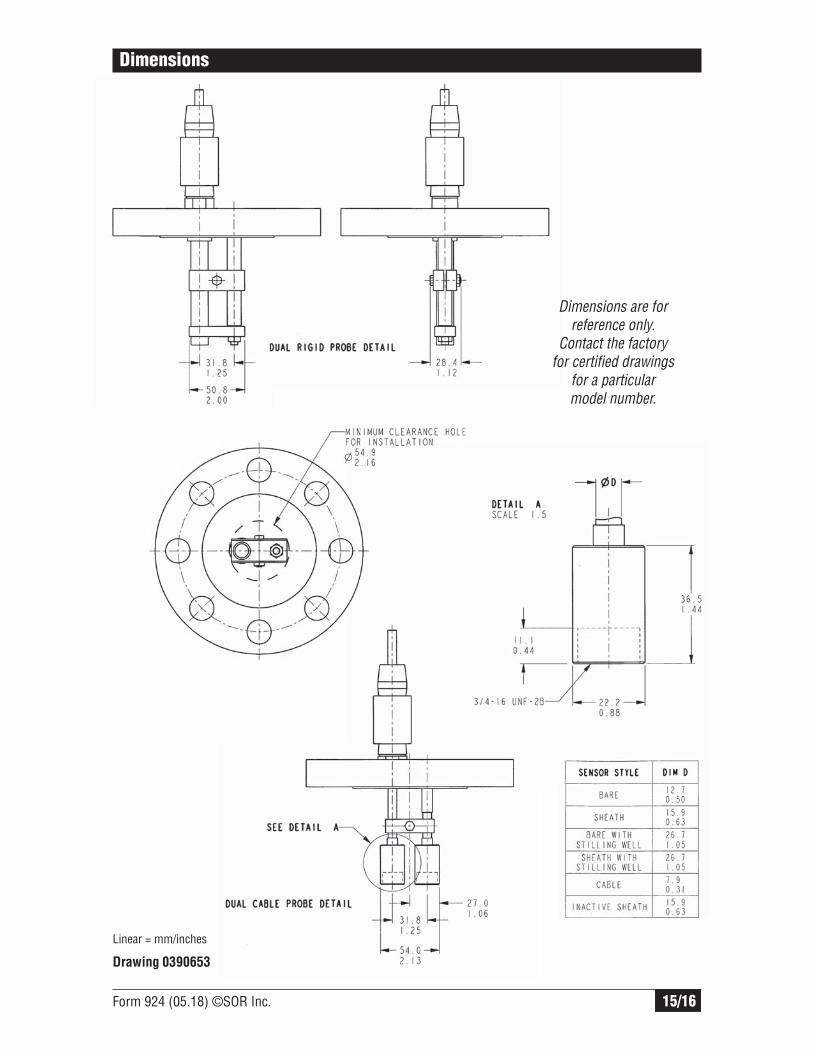
Dimensions
Dimensions are for reference only.
Contact the factory for certified drawings
for a particular model number.
Linear = mm/inches
Drawing 0390653
Form 924 (05.18) ©SOR Inc. 15/16
Dimensions
Linear = mm/inches
Drawing 0390653
Dimensions are for reference only.
Contact the factory for certified drawings
for a particular model number.

16/16 Form 924 (05.18) ©SOR Inc.
14685 West 105th Street, Lenexa, KS 66215 913-888-2630 800-676-6794 USA Fax 913-888-0767
Registered Quality System to ISO 9001
Printed in USA www.sorinc.com