vibration- and acceleration sensor / monitor canopen
TRANSCRIPT

Vibration- and Acceleration sensor / monitorCANopen interface + analogue output and switchesModel NVA115 / S3 or NVA120 / S3 with SIL2 status
Document No.: NVA 13482 HEDate: 09.03.2018
TWK-ELEKTRONIK GmbH D-40041 Düsseldorf Tel. +49 211 96117-0 [email protected] 85 Postbox 10 50 63 Fax +49 211 637705 www.twk.de
nContactless, wear-free sensor system in MEMS technology
nNumber of measurement axes: 2
nFrequency range: 0.1 ... 60 Hz (opt. 0.05 Hz)
nMeasuring range: ± 2 g
nInterfaces: CANopen safety SIL2 2 switching contacts SIL2 2 analogue outputs
nSpecial features:
Type of filter selectable 'Safety Shut off' SSO due to heavy strokes 'FFT' - fourier frequency detection "Switch off phasing" adjustable Various signal settings (RMS etc.)
nParameterisable via CANopenDesignThe sensor system is intended as a component for use e.g. in wind power plants to measure and evaluate vibrations in the mast head. Registration of dynamic accelerations by means of MEMS sensors (Micro-Electro-Mechanical System) with subsequent digitisation by a controller.
The device consists of an acceleration sensor, a controller unit and three types of output interface. The main feature is two safety switching contacts (potential-free), which can be used e.g. in the safety chain to undertake safety shut-off in the event of excessively high acceleration values.
Data output is carried out via the CANopen interface.
The standard or the safety profile can be selected.
There are additionally two analogue outputs 4 ... 20 mA, which can be optionally assigned to two of the three measurement axes.
Thanks to its high resistance to vibration and shock, the sensor is suitable for use in areas with rough environmental conditions.
Electrical connection is carried out using two or three con-nectors.
FunctionMEMS sensors are integrated circuits which are manufac-tured in silicon bulk micromechanics technology. They have a long service life and are very robust.
After determining the steady component and scaling, the measured values supplied by the acceleration sensor are
made available to the six filter units. The steady component arises as a result of installation which is not precisely ho-rizontal, with the result that part of the earth's gravitational field would also be measured. The offset which occurs in the measured vibration value curve (zero point shift) due to the steady component is determined by means of calculation (distribution of the positive and negative measured values around the zero point) and is subtracted. The pure alter-nating component is output within a matter of 20 seconds. This calculation takes place continually. This function can be shut off in the factory.
The filter units can be individually programmed in the filter characteristics for frequency selection in the factory (low pass or band pass). They can be assigned to axes x, y or z (in the case of x and y also to the resulting ones). Certain types of filter (kind, order, frequency limits) can be defined by the customer and can then be selected via CANopen.
The signals which are then available can be used for:
♦ activation of the safety switching outputs, time delay on demand (g limit values and assignment)
♦ output on CANopen / CANopen safety
♦ output on analogue outputs (amplification factor and assignment)
♦ selection of momentary or RMS output or peak or integral output
The majority of parameters can be set using the CANopen interface.
Detailed description: NVA 13660
SSO Safety
Function
NVA120
Vibration sensor / monitor NVA115 / S3 or NVA120 / S3
Date: 09.03.2018 Page 2 of 15 Document No. NVA 13482 HE
Description See document NVA13660 for detailed information
General informationThe vibration sensor measures on two axes in a frequency spectrum from 0.1 to 60 Hz (Option: 0.05 to 60 Hz). This spectrum can be subdivided into a maximum of 6 frequency ranges. The frequency ranges are set in the factory. All acceleration values acting within the relevant frequency window are registered and are output firstly as an analogue value (4 ... 20 mA, max. two outputs possible) and secondly as a digital value via CANopen or CANopen safety. The acceleration values which are present are additionally compared with limit values (maximum values). If these limit values are exceeded, relevant switching contacts switch (a maximum of two is possible). In normal operating status, the contacts are closed. There is a warning stage and a alarm stage. The limit values for these stages can be set in the factory or by the customer. After 30 seconds, the warning status is reset to normal operating status if the measured acceleration level are not exceeding the warning limit any more. The alarm status can only be deleted through a reset.
The measuring axis is x, y or z or the vector sum √(x²+y²) built from x and y.The acceleration value (instantaneous value) can be used directly or a mean value of the acceleration which occurs (RMS) may be used as the output value and the further processing value for the relay circuit. The time over which averaging is carried out can be set.
Filter characteristicsDigital pre-filtering is initially carried out in the MEMS sensor to extensively suppress higher-frequency interference vibrations (> ≈ 100 Hz), as they reveal comparatively high amplitudes due to the higher frequencies (1st-order FIR filter).The individual frequency bands are then realised in the downstream controller via digital 8th to 11th-order Chebichev filters (11th order in the lower frequency range, 8th order in the upper frequency range). Other types of filter can be prepared by TWK on customers demand (e.g. Butterworth of 2nd order). These filters can be activated by CANopen object 322x/08.The 6 filter units are of the same design; their characteristics can be set in the factory as desired by the customer. In the standard version, these filters (low-pass, band-pass and high-pass) are implemented as Chebichev filters. Chebichev filters are continuous frequency filters which are designed for the sharpest possible kinking of the frequency response at the limit frequency fg. To achieve this, amplification in the pass range or in the stop range is not monotonous but possesses a waviness which has to be defined. The higher the permissible waviness, the sharper the drop within an order. A distinction is made bet-ween type I and type II Chebichev filters. In the pass range, type I Chebichev filters possess an oscillating frequency response curve. Type II Chebichev filters have this frequency response waviness in the stop range and are also referred to as inverse Chebichev filters in the specialist literature. The case here involves type II.The maximum upper frequency limit of the vibrations to be measured is 60 Hz.The steady component - generally caused by axis inclination on inclined installation - is calculated out by means of averaging which is performed prior to filtering. As a result of this, the lower limit frequency - irrespective of filter - is around 0.1 Hz (opti-onally 0.05 Hz). Steady component suppression can be shut off in the factory.Figures 1 and 2 show examples of a possible frequency curve. The filter's output values are signed.The output of each filter 1 - 6 is further processed for the analogue outputs (filters 1 + 2 only), for output via CANopen and for the limit value relays which respond to the exceeding of acceleration limit values.
The filters' relevant output signal can be set via the CANopen interface as follows: - Output of the momentary value of the measured acceleration - Output of a mean value over time for the measured acceleration (RMS averaging time adjustable via CAN) - Output of a summarized value if the measured acceleration exceeds a customer defined limit Switching outputsThe switching outputs react to the amount of the filter's output value (amount = folding up of the negative half-waves of the measured vibration curve).The warning output is activated after exceeding the corresponding limit, i.e. the relay contact opens. The relevant relay drops off. It is reset when the limit is no longer reached for 30 s. Otherwise the time is extended.The alarm output is activated after exceeding the corresponding limit, i.e. the relay contact opens. The relay drops off and remains constantly triggered. It can only be deleted by resetting the system.The reference value is the amount of the currently measured vibration's momentary value. If a positive deviation event occurs 1 x, the corresponding relay is triggered. During normal operation, the relays are picked up. They drop off in the event of triggering or when the NVA is voltage-free.
Special features like an integral function, an FFT analysis and a self-test function are available (see NVA13660). Shut-off in a specific vibration phase which can be specified by the customer can also be set - important for the NVA115 or NVA120 as a mast vibration monitor.
Every NVA provides that the switching contacts switch immediately when the wind power plant is exposed to a heavy stroke or shock. The according limit value is parameterizable. This provides shock detection and a "Safety shut off" in cases of these heavy shock exposure: SSO.

Vibration sensor / monitor NVA115 / S3 or NVA120 / S3
Date: 09.03.2018 Page 3 of 15 Document No. NVA 13482 HE
Fig. 2: Example of a low pass filter fgo = 23 HzFig. 1: Example band pass filter fgu = 0.8Hz, fgo = 2.5 Hz
Examples for fiter output Amplitude vs f
Diagram for analogue output I0(a) (Not SIL2 capable)
Output: signednx, momentary valueny, momentary value
- 0 g +
4 mA
12 mA
20 mA
I [mA]
a [g]
0 g +
4 mA
20 mA
I [mA]
Output: absolute valuenx or y, RMS valuenx or y, Peak valuenS=√(x²+y²), RMS valuenS=√(x²+y²), momentary valuenIntegral 1 or 2
Following version is shown:CANopen + Analogue + Switches

Vibration sensor / monitor NVA115 / S3 or NVA120 / S3
Date: 09.03.2018 Page 4 of 15 Document No. NVA 13482 HE
FFTFrequency
Amplitude
FFT......
AmplitudeAmplitude
2ω0
3ω0
4ω0
5ω0
ω0
ω0
Frequency
Amplitude
Time
Time
In preparation is an NVA version which provides the output of the spectrum of measured frequencies via CANopen. This spec-trum is get by Fourier transformation (FFT) of the momentary value of the acceleration measurement versus time.
This functionality can be used for blade or tower frequency detection.
See two simple examples for such a transformation in the following diagrams.
Frequency detection by Fourier transformation FFT In preparation

Vibration sensor / monitor NVA115 / S3 or NVA120 / S3
Date: 09.03.2018 Page 5 of 15 Document No. NVA 13482 HE
Electrical datan Sensor system: MEMS acceleration sensorn Resolution: 4096 digits / g (9.81 m/s² = 1 g)n Operating voltage range: + 18 to + 30 VDCn Power consumption: ≤ 2 W (At VS = 24 VDC: IS = 80 mA, when both switching contacts ON)n Overvoltage protection and galvanic separation power supply - CANopen - housingn CAN interface: According to ISO/DIS 11898n Address setting: Via LMT / LSSn Terminating resistor: To be implemented separatelyn Max.transmission length: 200 m with no galvanic separation (also see CiA, DS 301)n Electrical connection: 2 x connector M12 - (Power supply / CANopen and switching outputs) 3 x connector M12 - (In addition BUS OUT) Optional: cablen CAN IC voltage rating: Maximum common mode voltage -7 to +12 V Maximum allowed voltage at pins ± 36 V
Environmental datan Operating temperature range: - 40 °C to + 70 °Cn Resistance to shock: 500 m/s² / 5 ms, according to DIN EN n Resistance to vibration: 10 Hz ... 2000 Hz / 100 m/s², according to DIN EN 60068-2-6n Protection type (DIN 40 050): IP 67 plug connection IP 69K housingn EMC: EN 61000-6-4 interference emission EN 61000-6-2 interference immunity EN 61000-4-2 (ESD) EN 61000-4-4 (burst) EN 61000-6-3 (emission)n Further standards: IEC 60068-2-52 - Salt mist test (Type NVA115) IEC 60068-2-30 - Damp heat, cyclic (Type NVA115) IEC 60068-2-78 - Damp heat, steady state (Type NVA115) IEC 60529 - Protection against water jets IPX6 (Type NVA115) IEC 20653 - Protection against high pressure steam jets IPX9K (NVA115)n Housing material: Aluminium AlSiMg1 (Stainless steel 1.4305 oder 1.4404 on request)n Weight: 0.4 kg
Programmable features
Parameters programmable via CANopen interfacen Measuring axis: x, y or z or √(x²+y²) separately for each filter ( means output) 1 - 6n Filtertype which is prepared by TWK due to customers requirements for each output 1 - 6n Signal type at filter output 1 - 6: momentary value, RMS mean value, peak value, integration valuen Averaging time for signal type 'RMS', degressive time for peak, integration timen Amplification for analogue outputs 4 ... 20 mA (Analoge outputs are assigned to filter 1 and 2)n Acceleration limit values (limit) for relay warning function n Acceleration limit values (limit) for relay alarm functionn Acceleration limit for calculation of integral n Filter ↔ relay assignmentn Time constants for delayed and phase-optimised switching output responsen Further limit values for delayed switching output response and heavy shock detectionn "Safety shut off" limit values
Technical data

Vibration sensor / monitor NVA115 / S3 or NVA120 / S3
Date: 09.03.2018 Page 6 of 15 Document No. NVA 13482 HE
Signal acquisitionn Number of axes: 2n Value output on analogue output: x and y as separate components or vector sum of x and y (resulting R)n Number of frequency bands: maximum of 6 (Setting ex works)nMeasuring range: ± 2 g for each axisn Sampling frequency: 120 to 800 Hz, depending on the frequency range of according filtern Accuracy of the measured acceleration value: 5 %n Maximum inclination vs. horizon: 15° (at angles >15° an error message will be transferred by CANopen)n Lower limit frequency: 0.1 Hz (optionally 0.05 Hz)n Upper limit frequency: 60 Hz
Signal outputn 1 CANopen interface with 4096 digits / gn 2 analogue outputs 0 (4) ... 20 mA (12-bit resolution)n 2 relays for warning and/or alarm function on exceeding limit values
System in general and Safetyn Data will be submitted subsequently
Technical data
1 2
Switching contact 1
3 4
Switching contact 2
Forc
ibly
gui
ded
rela
ys 3
+ 4
Controller
Forc
ibly
gui
ded
rela
ys 1
+ 2
Relay control and monitoring
Limit value relay technical data - SIL2
n Maximum switching current: 1 A at 30 VDC / VAC, 0.5 A at 60 VDC / VACn Maximum switching voltage: 60 VDC / VACn Maximum contact resistance ON: 0.5 Ω n Response time: 20 ms (ON and OFF)n Voltage protection between relay- and electronic circuit: 1 kV
2 relays connected in series form 1 switching contact → safe shut-off even under unfavourable voltage and current conditions. Contact sticking is prevented through a short shut-off time lag in the millisecond range.

Vibration sensor / monitor NVA115 / S3 or NVA120 / S3
Date: 09.03.2018 Page 7 of 15 Document No. NVA 13482 HE
CANopen communication profilen CiA DS 301 version 4.2 (Application Layer)n EN 50325-5 (Safety protocol)n CiA DSP 401 version 3.1 (Profile for I/O devices – Part 1: Generic I/O modules)n CANopen output code: signed 16-bit
CANopen technical data
Output level according to ISO/DIS 11898
5
4
3
2
1
0
Bus
pege
l / V
1)
2,5
3,5 CAN_H
1,5
CAN_L
rezessiv
1) bei Common-Mode-Spannung = 0V
dominant rezessiv
t
Bus activation according to ISO / DIS 11898
* *
CAN +
CAN -
CAN +
CAN -
CAN-Bus
TWK
-CA
Nop
enS
ubsc
riber
Terminating resistor (120 )*
Furth
erTW
K-C
AN
open
Sub
scrib
er
Safety parameters
Standard EN 13849-1:2008Vibration sensor at 25° Cn Category: 2 n MTTFd (Years): 106n CCF: fulfilledn DC [%]: 94,8n PL: d
Standard EN 61508:2010 and EN 62061
Vibration sensor at 25° Cn HFT: 0n T1[s]: ~10.000n SFF [%]: 96,8n PFH [1/h]: 5,597 10-8
n SIL: 2
Vibration sensor / monitor NVA115 / S3 or NVA120 / S3
Date: 09.03.2018 Page 8 of 15 Document No. NVA 13482 HE
Data format CANopen - SRDO
Output data
n Current output A: 0 to 20 mA B: 4 to 20 mA Accuracy: ± 10 µA at room temperature, ± 50 µA over the entire temperature range Load resistance: 0 ... 500 Ω
Analogue technical data (Not SIL2 capable)
The momentary values of fil-ters 1 and 2 can be output via the analogue outputs. With CANopen, they can be read out via relevant objects. In this case filters 3 to 6 via the PDO (e.g. for cyclical output), as it has a maximum size of 8 bytes. See NVA 13660 specifications.
Output circuits
Output B12 Bit
4-20 mAIo = 4 - 20 mAR = 0 - 0.5 k
Io
L
RLDA
R = 0 - 0.5 kIo = 0 - 20 mA
L
Output A
A0-20 mA
12 Bit
D LR
Io
Datenformat CANopen - PDO For profile version S0 in order number
Data Byte 0 Data Byte 10 1 2 3 4 5 6 7 8 9 101112131415LSB MSB
Filter 3
Data Byte 2 Data Byte 30 1 2 3 4 5 6 7 8 9 101112131415LSB MSB
Filter 4
Data Byte 4 Data Byte 50 1 2 3 4 5 6 7 8 9 101112131415LSB MSB
Filter 5
Data Byte 6 Data Byte 70 1 2 3 4 5 6 7 8 9 101112131415LSB MSB
Filter 6
Data format CANopen Safety for Filters 3 to 6
Valid for SRDO - normal and bit-inverted
Data Byte 0 Data Byte 10 1 2 3 4 5 6 7 8 9 101112131415LSB MSB
Filter 3
Data Byte 2 Data Byte 30 1 2 3 4 5 6 7 8 9 101112131415LSB MSB
Filter 4
Data Byte 4 Data Byte 50 1 2 3 4 5 6 7 8 9 101112131415LSB MSB
Filter 5
Data Byte 6 Data Byte 70 1 2 3 4 5 6 7 8 9 101112131415LSB MSB
Filter 6
The momentary values of fil-ters 1 and 2 can be output via the analogue outputs. With CANopen, they can be read out via relevant objects. In this case filters 3 to 6 via the SRDO (e.g. for cyclical output), as it has a maximum size of 8 bytes. See NVA 13660 specifications.
Attention: The analogue output is not compliant according to SIL2 category and to safety functionality due to the fact it provi-des no safe data transmission.

Vibration sensor / monitor NVA115 / S3 or NVA120 / S3
Date: 09.03.2018 Page 9 of 15 Document No. NVA 13482 HE
Order number
* The basic versions according to the data sheet bear the number 01. Deviations are identified with a variant number and are documented in the factory. The special version in accordance with the table on page 9 is reflected in the variant number.
NVA 115 - A 6 2 2 - 2 S3 S3 V1 N 01
NVA
A
6
2
2
2
S0S3
S1S2S3
V1V2V3
N
01Electrical and / or mechanical variants *Standard
Output interface:CANopen / CANopen safety
Galvanic separation ǂ (see pages 11 and 12): -VS ǂ CAN_GND ǂ screen/housing → recommended-VS = CAN_GND ǂ screen/housing -VS = CAN_GND = screen/housing
Electrical connection (see below and on pages 11 and 12):1 x device connector M12, 4/5-pin2 x device connector M12, 4/5-pin 3 x device connector M12, 4/5-pin
Profile:CANopen standard profile and SIL2 switching outputsCANopen Safety profile and SIL2 switching outputs
Measuring range:2 g = approx. 20 m/s² - higher values on request
Number of analogue outputs 0 (4) ... 20 mA:0, 1 or 2
Number of switching outputs:0, 1 or 2 - independent of each other and galvanically separated
Number of frequency filters:1 to a maximum of 6 - set in the factory (frequency bands)
Housing material:Aluminium AlMgSi1 (other materials, e.g. stainless steel, on request)
Design form:115120
Design form 115 mm Design form 120 mm
Vibration sensor / monitor NVA with CANopen interface, switching and analogue outputs
Comments on connector designs:
Design without analogue outputs: 1 or 2 connectors can be selected for supply voltage + bus connection.The second is intended for BUS-OUT. A further connector contains the SIL2 switching contacts.Design with analogue outputs: supply voltage + bus connection are located on connector 1 and the analogue outputs on con-nector 2 (socket). A third connector contains the SIL2 switching contacts. No BUS-OUT is provided in this case.Special designs with 8-pin connectors and/or sockets with customer-specific assignments are possible on request.
M12, 5-pin, female, A-coded: STK5GS56, angled: STK5WS58M12, 5-pin, male, A-coded: STK5GP90, angled: STK5WP102M12, 4-pin, female, B-coded: STK5GS67, angled: STK5WS87 (5 pole connector is suitable for 4 pole as well)(EMC-resistant, metal version)
Order Code format - mating connectors (to be ordered separately)
Vibration sensor / monitor NVA115 / S3 or NVA120 / S3
Date: 09.03.2018 Page 10 of 15 Document No. NVA 13482 HE
Further informations
Documentation, EDS file, etc.
n The following documents can be found in the Internet under www.twk.de in the documentation area NVA model (letter "N") Data sheet No. NVA 13482 Specification No. NVA 13660 CRC checksum programme for parameterisation. Link: www.twk.de/files/CRC-Calculator20.zip Certificate SIL2 when available
n The following are available on request: EDS file Bit map image file Electrical connection assignment, if required CRC checksum programme for parameterisation Description of the filter and programming settings (individually for each pre-set device, therefore on request only)
n Supply source for the listed CANopen specifications: CAN in Automation (CiA), Kontumazgarten 3, D-90429 Nuremberg (Email: [email protected], www.can-cia.org)
With this safety design, all changes to the adjustable parameters must be confirmed with a checksum. This checksum must be transmitted to the NVA after changing the parameters. The checksum can be determined using TWK software for a PC/notebook. All alterable parameters are entered in this programme, whereupon the checksum is calculated. Only when the correct checksum appropriate to the set parameters is transmitted to the NVA can the device be set to 'operational' operating status.
When changing parameterization data (limit values for switching contacts, assignments, etc.), the relevant data valid flags will be set to 0 automatically. The data valid flags must then be activated again. This procedure makes sure that no unintentional changes which affect the SIL2 switching contact functions are undertaken by the user.
(Also see: parameterisation recommendation for NVA115 / S3 or NVA120 / S3 in the NVA 13660 specifications)

Vibration sensor / monitor NVA115 / S3 or NVA120 / S3
Date: 09.03.2018 Page 11 of 15 Document No. NVA 13482 HE
Note: The recommended version is V1 with full galvanic separation. This offers maximum EMC resistance, maximum CANopen data transfer security and thus maximum operating safety.Versions V2 and V3 are special versions which must be compatible with the structure (topology) of the CANopen bus system in the customer application (→ control system and other CANopen subscribers). Operating safety or data transfer security may otherwise be affected.
This is the contact assignment for the standard version. Other versions may have a different contact assignment. In this case, please observe connection assignment TY enclosed with each device.Different M12 connector combinations or assignments are possible at the request of the customer.For the following description and pictorials is valid:Viewed looking at the PIN side of the connector installed in the NVA.
There is one connector for Bus-In and Bus-Out each for the NVA / S3 without analogue outputs.If there is only Bus-In, the female connector Bus-Out is omitted.
Standard design plug connection and pin assignment for supply and CAN bus
Connector for operating voltage and CAN bus Viewed looking at the contacts
12
34 5
253 1
4
M12, Pins, A-coded M12, socket, A-coded
BUS-OUT connector for operating voltage and CAN bus If available → 3-connector versionViewed looking at the contacts
V1: CAN_GND and UB galvanically separated (ǂ). Screening/housing galvanically separated (ǂ)This version is recommended and provides complete galvanic separation. Power supply and CAN_GND is galvanically separated. The housing and the screening of the cable is galvanically separated as well. The screening of the cable comes to the housing of the NOCN via the housing of the mating plug.
PIN Function1 CAN GND2 Operating voltage + VS
3 Operating voltage - VS
4 CAN_HIGH (+)5 CAN_LOW (-)
V2: CAN_GND and UB not galvanically separated (=). Screening/housing galvanically separated (ǂ)This version provides partly galvanic separation. Power supply and CAN_GND are not galvanically separated. The housing and the screening of the cable are galvanically separated from power supply and CAN_GND. The screening of the cable comes to the housing of the NOCN via the housing of the mating plug and/or Pin 1 of the connector. Please note the maximum voltage rating of the CAN interface IC.
PIN Function1 Screen (Cable / housing)2 Operating voltage + VS
3 Operating voltage - VS and CAN_GND4 CAN_HIGH (+)5 CAN_LOW (-)

Vibration sensor / monitor NVA115 / S3 or NVA120 / S3
Date: 09.03.2018 Page 12 of 15 Document No. NVA 13482 HE
Each switching contact is galvanically separated.
Standard design plug connection and pin assignment for supply and CAN bus
V3: CAN_GND and UB not galvanically separated (=). Screening/housing not galvanically separated (=)This version provides no galvanic separation. Power supply and CAN_GND are not galvanically separated. The housing and the screening of the cable are not galvanically separated from power supply and CAN_GND. The screening of the cable comes to the housing of the NOCN via the housing of the mating plug and/or Pin 1 of the connector. Please note the maximum voltage rating of the CAN interface IC.
PIN Function1 Screen (Cable / housing) - shorted to pin 3 -2 Operating voltage + VS
3 Operating voltage - VS and CAN_GND- shorted to pin 1 -
4 CAN_HIGH (+)5 CAN_LOW (-)
Standard design plug connection and pin assignment for analogue outputs (Not SIL2 capable)
253 1
4
M12, socket, A-coded
Connector for analogue outputs If available → 3-connector version. In this case the female Bus-Out connector is omitted.Viewed looking at the contacts
PIN Connector M12, 4-pin, socket, A-coded1 Analogue output 1: 0 (4) ... 20 mA2 Analogue output 2: 0 (4) ... 20 mA3 Multifunctional pin: NVA-Reset (on request)4 Reference potential for pins 1 to 3 (- VS)5 Not connected
Connector for SIL2 switching contactIf availableViewed looking at the contacts
PIN Connector M12, 4-pin, pins, B-coded1 Safety contact 1 / (13)2 Safety contact 1 / (14)3 Safety contact 2 / (23)4 Safety contact 2 / (24)
M12, pins, B-coded
Standard design plug connection and pin assignment for SIL2 switching contacts
14
32
(13) / (14): normally open contact of switching contact 1(23) / (24): normally open contact of switching contact 2
Vibration sensor / monitor NVA115 / S3 or NVA120 / S3
Date: 09.03.2018 Page 13 of 15 Document No. NVA 13482 HE
Plug connection and pin assignment Special design on request
PIN Connector M12, 5-pin, pins, A-coded1 Operating voltage + VS
2 Operating voltage - VS
3 Do not connect
4 Do not connect
5 Do not connect
PIN Connector M12, 5-pin, pins, A-coded1 Do not connect
2 Do not connect
3 CAN_LOW (-)4 CAN_HIGH (+)5 CAN_GND
PIN Connector M12, 4-pin, pins, B-coded1 Safety contact 1 / (13)2 Safety contact 1 / (14)3 Safety contact 2 / (23)4 Safety contact 2 / (24)
12
34 5
14
32
12
34 5

Vibration sensor / monitor NVA115 / S3 or NVA120 / S3
Date: 09.03.2018 Page 14 of 15 Document No. NVA 13482 HE
Installation drawing Type NVA115
Version with 3 connectors
Dimensions in mm
Materials used
Aluminium housing: AlMgSi1Stainless steel housing: On requestConnector: Nickel-plated brassSealing rings: NBR
29
14 3
147.25 ±0.2
132.25 ±0.2
35±0
.15.
5
A
Sensor connector M124-pole, pinsB-coded, aligned
All flange connectors are aligned for overmoulded mating connectors.Plug design is exemplary.
S1 S2
S3 115.5 ±0.2
Sensor connector M125-pole, pinsA-coded, aligned
55
Sensor connector M125-pole, pinsA-coded, aligned
67.25 ±0.2
View A
13ca
.
45°
Position coding groove
45°
45°Position coding pin
TOP
-x+x
+y-yA
CC
EL
Vibration sensor / monitor NVA115 / S3 or NVA120 / S3
Date: 09.03.2018 Page 15 of 15 Document No. NVA 13482 HE
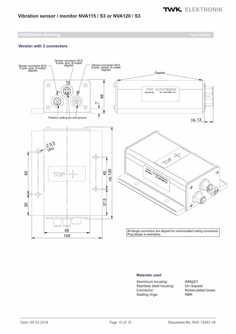
Installation drawing Type NVA120
Materials used
Aluminium housing: AlMgSi1Stainless steel housing: On requestConnector: Nickel-plated brassSealing rings: NBR
Version with 3 connectors
Sensor connector M125-pole, socket, A-coded
aligned
7
48
100
65
Position coding pin and groove
Gasket
13ca.
13
0ca
.
Sensor connector M125-pole, pins, A-coded
aligned
S1
S3
S2
All flange connectors are aligned for overmoulded mating connectors.Plug design is exemplary.
Sensor connector M124-pole, pins, B-coded
aligned
60
30
O 5.5
(4x)
37
.54
5