rf control requirements in energy recovery linacs · llrf workshop, l. merminga ... 2 3 4 5 6 1 2 3...
TRANSCRIPT

Operated by the Southeastern Universities Research Association for the U. S. Department of EnergyThomas Jefferson National Accelerator Facility
LLRF Workshop, L. Merminga 4/25/2001
RF Control Requirements in
Energy Recovery Linacs
Lia Merminga
Jefferson Lab
Newport News, VA
Workshop on Low Level RF Controls for Superconducting Cavities
Jefferson Laboratory, April 25-27 2001

Operated by the Southeastern Universities Research Association for the U. S. Department of EnergyThomas Jefferson National Accelerator Facility
LLRF Workshop, L. Merminga 4/25/2001
Outline
� Energy Recovery Linacs (ERLs)
• ERL-based FELs / The JLab IR FEL and FEL Upgrade
• ERL-based Synchrotron Light Sources / The Cornell ERL (Proposed)
• ERL-based Colliders: eRHIC, EIC (Conceptual Designs)
� Efficiency of ERLs
• Power Requirements
� Amplitude and Phase Stability Requirements
� RF Stability
� Conclusions
Operated by the Southeastern Universities Research Association for the U. S. Department of EnergyThomas Jefferson National Accelerator Facility
LLRF Workshop, L. Merminga 4/25/2001
Energy Recovery Linacs
� Energy recovery is the process by which the energy invested in accelerating a beam is returned to the rf cavities by decelerating the same beam.
� There have been several energy recovery experiments to date, the first one at the Stanford SCA/FEL.
� Same-cell energy recovery with cw beam current up to 5 mA and energy up to 50 MeV has been demonstrated at the Jefferson Lab IR FEL. Energy recovery is used routinely for the operation of the FEL as a user facility.

Operated by the Southeastern Universities Research Association for the U. S. Department of EnergyThomas Jefferson National Accelerator Facility
LLRF Workshop, L. Merminga 4/25/2001
The JLab 1.7 kW IRFEL and Energy Recovery Demonstration
G. R. Neil, et al., “Sustained Kilowatt Lasing in a Free Electron Laser with Same-Cell Energy Recovery,” Physical Review Letters, Volume 84, Number 4 (2000)
IR Wiggler
BeamTransport
10 m
Injector
Linac
OpticalSystem

Operated by the Southeastern Universities Research Association for the U. S. Department of EnergyThomas Jefferson National Accelerator Facility
LLRF Workshop, L. Merminga 4/25/2001
Energy Recovery WorksGradient modulator drive signal in a linac cavity measured without energy recovery (signal level around 2 V) and withenergy recovery (signal level around 0).
GASK
-0.5
0
0.5
1
1.5
2
2.5
-1.00E-04 0.00E+00 1.00E-04 2.00E-04 3.00E-04 4.00E-04 5.00E-04
Time (s)
Vo
lta
ge
(V
)

Operated by the Southeastern Universities Research Association for the U. S. Department of EnergyThomas Jefferson National Accelerator Facility
LLRF Workshop, L. Merminga 4/25/2001
Energy Recovery Works (cont’d)
0
1
2
3
4
5
6
1 2 3 4 5 6 7 8 Avg.
Beam off1.1 mA, No ER1 mA with ER2.4 mA with ER3 mA with ER3.5 mA with ER
RF
Pow
er (
kW)
Cavity number
With energy recovery the required linac rf power is ~ 16 kW, nearly independent of beam current. It rises to ~ 36 kW with no recovery at 1.1 mA.

Operated by the Southeastern Universities Research Association for the U. S. Department of EnergyThomas Jefferson National Accelerator Facility
LLRF Workshop, L. Merminga 4/25/2001
The JLab 10 kW FEL Upgrade

Operated by the Southeastern Universities Research Association for the U. S. Department of EnergyThomas Jefferson National Accelerator Facility
LLRF Workshop, L. Merminga 4/25/2001
Cornell ERL
DBA=Double Bend Acromat

Operated by the Southeastern Universities Research Association for the U. S. Department of EnergyThomas Jefferson National Accelerator Facility
LLRF Workshop, L. Merminga 4/25/2001
Cornell ERL Prototype
700 cm
341 cm
1173 cm
2 m1 m0
540 cm
21.2 m
12.4 m
- Dipole- Quadrupole- Kick- Vacuum Valves
to Dump

Operated by the Southeastern Universities Research Association for the U. S. Department of EnergyThomas Jefferson National Accelerator Facility
LLRF Workshop, L. Merminga 4/25/2001
Linac–Ring Collider: Schematic Layout
Energy Recovery Electron Linac
Proton Ring
Electron Beam Dump
Polarized Electron Source

Operated by the Southeastern Universities Research Association for the U. S. Department of EnergyThomas Jefferson National Accelerator Facility
LLRF Workshop, L. Merminga 4/25/2001
Benefits of Energy Recovery
� Required rf power becomes nearly independent of beam current.
� Increases overall system efficiency.
� Reduces electron beam power to be disposed of at beam dumps (by ratio of Efin/Einj).
� If the beam is dumped below the neutron production threshold, then the induced radioactivity (shielding problem) will be reduced.
Operated by the Southeastern Universities Research Association for the U. S. Department of EnergyThomas Jefferson National Accelerator Facility
LLRF Workshop, L. Merminga 4/25/2001
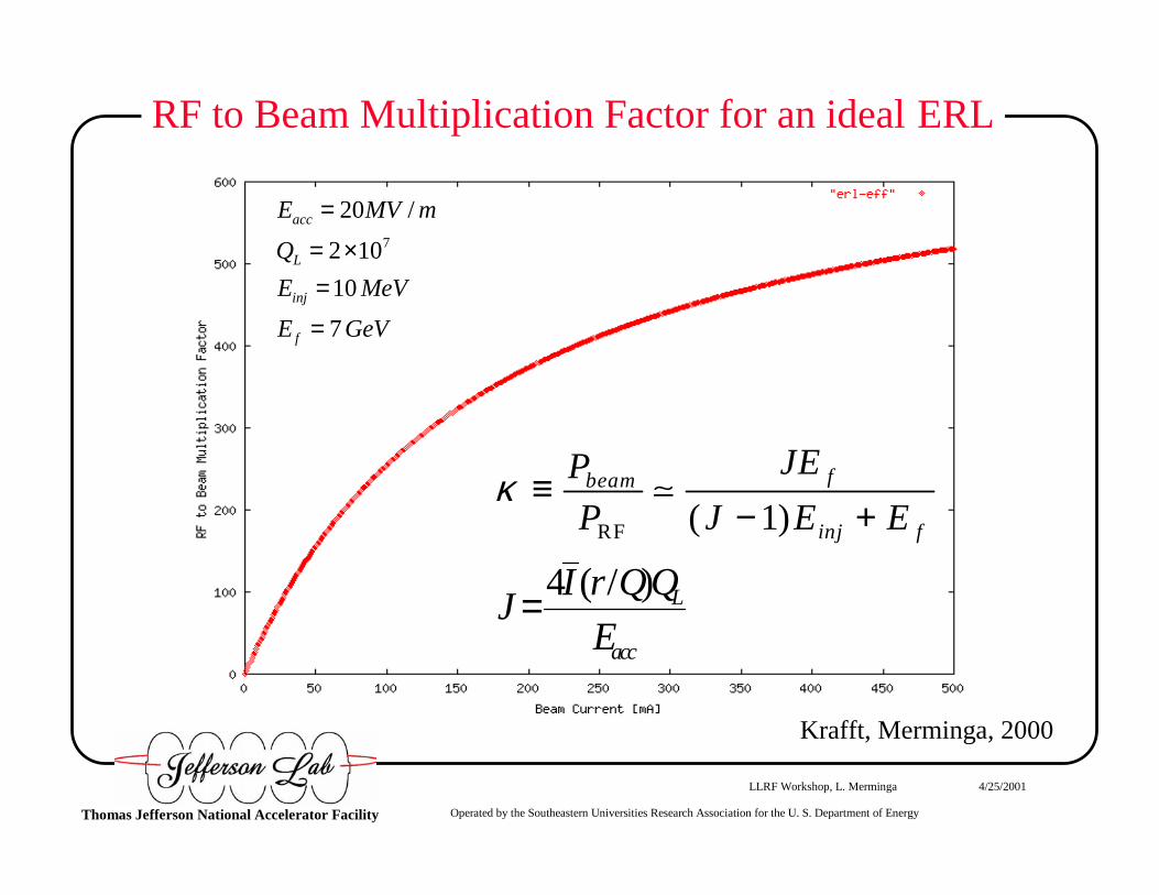
RF to Beam Multiplication Factor for an ideal ERL
RF ( 1)fbeam
inj f
JEP
P J E Eκ ≡
− +�
4 ( / ) L
acc
I r QQJ
E=
7
20 /
2 10
10
7
acc
L
inj
f
E MV m
Q
E MeV
E GeV
=
= ×=
=
�
�
Krafft, Merminga, 2000
Operated by the Southeastern Universities Research Association for the U. S. Department of EnergyThomas Jefferson National Accelerator Facility
LLRF Workshop, L. Merminga 4/25/2001
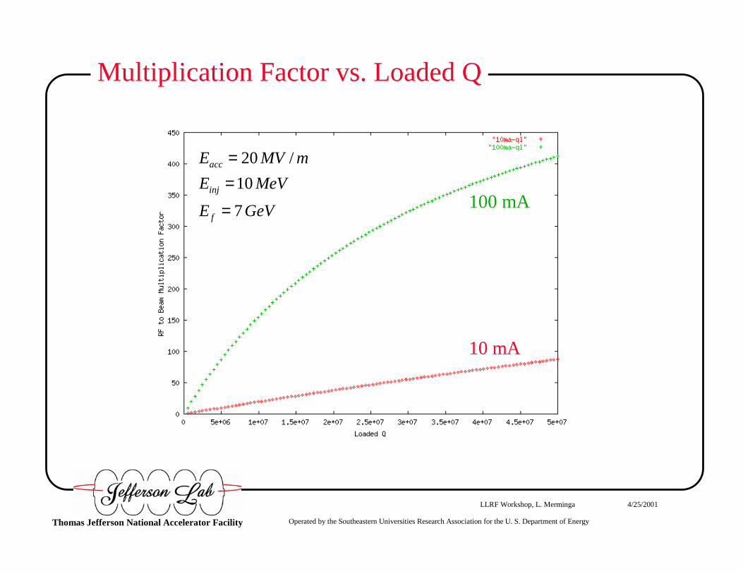
Multiplication Factor vs. Loaded Q
100 mA
10 mA
20 /
10
7
acc
inj
f
E MV m
E MeV
E GeV
==
=
�
�
�

Operated by the Southeastern Universities Research Association for the U. S. Department of EnergyThomas Jefferson National Accelerator Facility
LLRF Workshop, L. Merminga 4/25/2001
Can we further improve the ERL efficiency?
� In practice, for an ideal ERL (Itot=0, ∆ψ=180o):
δfm is the maximum microphonic noise to be controlled
� In order to further improve the ERL efficiency, the following questions are of primary importance:
• What is the maximum achievable QL?
• Microphonics control?
• Lorentz force detuning?
2
0
0
21 m
opt
Q f
f
δβ
= +

Operated by the Southeastern Universities Research Association for the U. S. Department of EnergyThomas Jefferson National Accelerator Facility
LLRF Workshop, L. Merminga 4/25/2001
Real ERLs
� Phases may not differ by precisely 180o
• Typical expected path length control adjustment leads to ~ 0.5o
deviation from 180o
• In an FEL, if machine is setup so that beam current vectors cancel with FEL on, then with FEL off, there can be up to 5o deviation from perfect cancellation
� Beam loss may occur, resulting in beam vectors of unequal magnitude
� Beam current fluctuations
⇒ All of the above give rise to a net beam loading vector, typically of
reactive nature in the case of phase errors
⇒ Increase of rf power requirements and reduction of κ

Operated by the Southeastern Universities Research Association for the U. S. Department of EnergyThomas Jefferson National Accelerator Facility
LLRF Workshop, L. Merminga 4/25/2001
Energy Recovery Phasor Diagram
Operated by the Southeastern Universities Research Association for the U. S. Department of EnergyThomas Jefferson National Accelerator Facility
LLRF Workshop, L. Merminga 4/25/2001
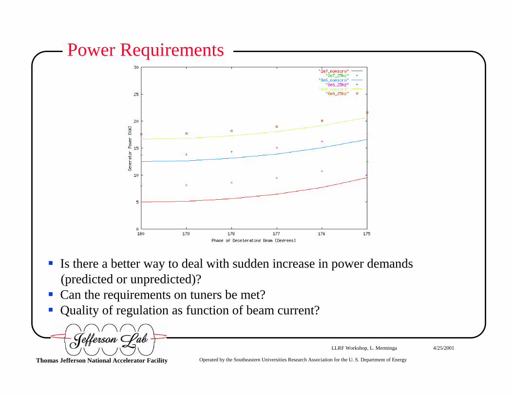
Power Requirements
� Is there a better way to deal with sudden increase in power demands (predicted or unpredicted)?
� Can the requirements on tuners be met? � Quality of regulation as function of beam current?

Operated by the Southeastern Universities Research Association for the U. S. Department of EnergyThomas Jefferson National Accelerator Facility
LLRF Workshop, L. Merminga 4/25/2001
RF Control (Linac)

Operated by the Southeastern Universities Research Association for the U. S. Department of EnergyThomas Jefferson National Accelerator Facility
LLRF Workshop, L. Merminga 4/25/2001
RF Control (Injector)

Operated by the Southeastern Universities Research Association for the U. S. Department of EnergyThomas Jefferson National Accelerator Facility
LLRF Workshop, L. Merminga 4/25/2001
Amplitude and Phase Stability Requirements
� End users impose certain phase and amplitude stability requirements in order for the energy spread and timing jitter specifications at the interaction point (FEL, undulator, interaction region) to be met
� These requirements determine characteristics of the LLRF controlsystem, including gain and bandwidth of the feedback loops
� In ERLs, additional constraints on the LLRF system design may beimposed due to possible longitudinal instabilities
Operated by the Southeastern Universities Research Association for the U. S. Department of EnergyThomas Jefferson National Accelerator Facility
LLRF Workshop, L. Merminga 4/25/2001
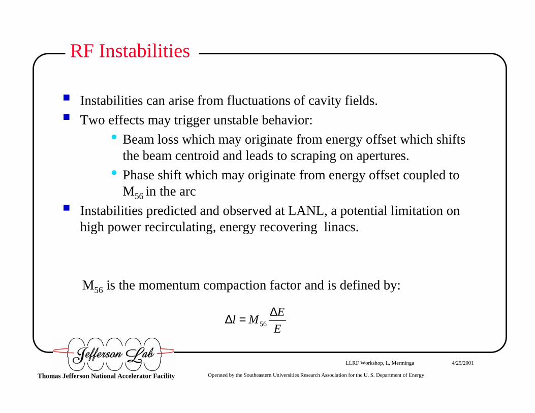
RF Instabilities
� Instabilities can arise from fluctuations of cavity fields.
� Two effects may trigger unstable behavior:
• Beam loss which may originate from energy offset which shifts the beam centroid and leads to scraping on apertures.
• Phase shift which may originate from energy offset coupled to M56 in the arc
� Instabilities predicted and observed at LANL, a potential limitation on high power recirculating, energy recovering linacs.
M56 is the momentum compaction factor and is defined by:
56
El M
E
∆∆ =

Operated by the Southeastern Universities Research Association for the U. S. Department of EnergyThomas Jefferson National Accelerator Facility
LLRF Workshop, L. Merminga 4/25/2001
RF STABILITY FLOW CHART∆ Ε
∆G
Energy Aperture
M56
Freq. shift
Beam loss ∆ P light Phase shift
∆ Vb
Feedback
∆ Vc
X

Operated by the Southeastern Universities Research Association for the U. S. Department of EnergyThomas Jefferson National Accelerator Facility
LLRF Workshop, L. Merminga 4/25/2001
RF Stability Model
� Developed model of the system that includes beam-cavity interaction, low level rf feedback and the FEL; it was solved analytically and numerically
� Model predicts instability exists in the IRFEL, however is controlled by LLRF feedback
� When FEL is off, experimental data from the IRFEL are quantitatively consistent with the model. With FEL on, model reproduces data qualitatively

Operated by the Southeastern Universities Research Association for the U. S. Department of EnergyThomas Jefferson National Accelerator Facility
LLRF Workshop, L. Merminga 4/25/2001
FEL/RF INTERACTION: EXPERIMENT VS MODEL

Operated by the Southeastern Universities Research Association for the U. S. Department of EnergyThomas Jefferson National Accelerator Facility
LLRF Workshop, L. Merminga 4/25/2001
Conclusions
� Energy recovery linacs are very efficient devices for certain applications
� We have asked two questions:
• Can we increase the efficiency of ERLs by optimizing the rf control system design?
• Can we ensure stability at high average currents with better rf control system design?