review of literature - inflibnetshodhganga.inflibnet.ac.in/bitstream/10603/38745/11/11_chapter...
TRANSCRIPT

REVIEW OF LITERATURE

REVIEW OF LITERATURE
2.1 Fuel Cell
Fuel cells are electrochemical devices that generate electricity by converting chemical
energy associated with the oxidation of fuel into direct current (DC) electricity. Since no
combustion reaction is associated, fuel cells do not produce any of the undesirable products
normally associated with the oxidation of fossil fuels in the conventional energy conversions
system. Thus fuel cells are environmentally friendly.
In the fuel cell electricity is generated by the reaction between a fuel supply and an
oxidizing agent. Hydrogen acts as the fuel and oxygen as the oxidizer. The hydrogen is fed
continuously to the anode (negative electrode) compartment while oxygen is fed continuously to
the cathode (positive electrode) compartment which is separated by an electrolyte which serves
as the ion conductor (Grant, 2003). In the anode, the hydrogen is broken down into two
components: hydrogen nucleus (proton) and an electron. The fuel cell was first demonstrated by
a Welsh scientist Sir William Robert Grove in 1839 although the idea was first discovered by
Christian Friedrich Schonbein , a German scientist in 1838.The efficiency of a fuel cell is
dependent on the amount of power drawn from it , i.e., the more power drawn , the lower the
efficiency. A typical fuel cell produces a voltage from 0.6 V to 0.7 V at full rated load
(Larminie and Dicks, 2000). The electron is transferred to the cathode through the electric
circuit whereas the proton migrates from the anode to the cathode through the electrolyte where
it binds with the proton and the oxygen to form water which is the chemical product of the fuel
cell (Logan, 2008).
Different types of fuel cells are there characterized by their electrolytes and different
temperature of operation such as the Proton Exchange Membrane Fuel cell (PEMFC),
Phosphoric acid Fuel cell (PAFC), Solid oxide Fuel cell (SOFC), Alkaline Fuel cell (AFC) , Zinc
Air Fuel cell (ZAFC) and Microbial Fuel cell (MFC).
2.2 Microbial Fuel Cell
Microbial fuel cell (MFC) is a device that converts organic matter to electricity using
microorganisms as the biocatalyst. The development of processes that can use bacteria to
produce electricity represents a fantastic method for bioenergy production as the bacteria are

self-replicating, and thus the catalysts for organic matter oxidation are self-sustaining (Logan,
2008). Most MFCs contain two electrodes separated into one or two chambers that are operated
as a completely mixed reactor. The anode is present in the fuel cell or anode chamber. In the fuel
cell oxidation occurs and electrons released from the fuel substrate are passed onto the anode in
the fuel cell. Electron travels into the cathode chamber by an electrical connection. The cathode
is the site where reduction i.e., the gain of electrons occurs by the oxidant present in the cathodic
chamber. Simultaneously the positive ions generated in the anode chamber travel into the
cathode chamber generally by way of an ion permeable membrane between the two chambers
which completes the electrical circuit.
The possibility of direct conversion of organic material in wastewater to bio-electricity is
exciting, but fundamental understanding of the microbiology and further development of
technology is required. With continuous improvements in microbial fuel cell, it may be possible
to increase power generation rates and lower their production and operating cost (Logan, 2008).
Thus, the combination may help in saving of millions of rupees as a cost of wastewater treatment
at present.
The first observation of electrical current generated by bacteria is credited to Potter
(Potter, 191l). A very few practical advances were achieved in this field even 55 years later
(Lewis, 1966). In 1990s, work on MFCs began to increase (Allen and Bennetto, 1993) but the
breakthrough in MFCs occurred in 1999 when it was recognized that mediators did not need to
be added (Kim et al., 1999).
Iron reduction coupled with glucose oxidation can be described by the following reaction
(Bilgin et al., 2005):
24Fe3++ C6H12O6+ 6H2O 6CO2 +24Fe2+ +24H+ ……….. (3)
The reduced iron is oxidized at the electrode, giving Fe (III) as follows:
Fe2+ e- +Fe3+ ……….. (4)
The electrons are received at the cathode by oxygen, producing water:
O2 +4e_ +4H+ 2H2O ………... (5)
Acidophilic organisms and systems capable of transferring electrons at a high rate to the
electrodes may have significant potential for generation of electricity via microbial fuel cells.

Fig. 2.1: A schematic diagram of Microbial fuel cell.
The popularity of the MFC technology has risen exponentially during the last few years
because there is a hope that MFCs will allow harvesting the energy stored in wastewater directly
in the form of electricity. This should place MFCs directly in competition with anaerobic
digestion (AD) as a more sustainable and environment-friendly alternative to conventional
activated sludge (CAS). Loading rate plays important role in MFC operation and at higher loads,
performance appears to decrease quickly (Rabaey et al., 2003). MFCs are highly efficient as a
biological treatment system at low to moderate loading rates, possibly achieving high COD
removal, depending on the substrate (Liu and Logan, 2004).The part of the energy bound to
wastewater is diverted into electricity in an MFC results in reduced sludge accumulation as
compared with CAS (Rabaey and Verstraete, 2005).
2.3 MFC configuration
Practical applications of MFCs will require that we develop a design that will not only
produce high power and columbic efficiencies, but one that is also economical to mass produce
based on the materials being affordable and the manufacturing process being practical to
implement on a large scale. While the reactor designs that will ultimately prove to meet these
requirements of power, efficiency, stability, and longevity are still being developed, studies
showed that scalable and economical systems can be developed using graphite fibre brush
electrodes and tubular cathodes immersed together in a tank. However, such a reactor has yet to
be built at pilot or large scale till date. Thus, the final design and the materials that will
ultimately be used in a large-scale system remain unproven at this time.
Applications of microbial fuel cells (MFCs) promise energy-efficient conversion of
dissolved organics and electron donors and even the generation of useful carbon neutral power
(Rabaey and Verstraete, 2005). Certainly in the context of energy efficient wastewater
treatment, considerable attention has been received (Rabaey et al., 2005). The process that
drives them, extracellular electron transfer, has in recent years shown high versatility in the type
of conversions that can be achieved (Rabaey et al., 2007). Therefore, a broader array of
applications is emerging, ranging from cathode driven denitrification to anode driven sulphide
removal (Clauwaert et al., 2007).
To underline their versatility beyond energy generation, MFCs should rather be
designated ‘Bio-Electrochemical Systems’. In Bio-Electrochemical Systems, bacteria have been
found to deploy several strategies to use electrodes as electron acceptors. Bacteria produce or use
soluble components as electron carriers (Rabaey et al., 2005). A direct contact is established
either through membrane-bound complexes (Bond and Lovely, 2003) or through conductive
nanowires (Reguera et al., 2005; Gorby et al., 2006).Those processes have been extensively
studied for electrons flowing away from bacteria but how bacteria take in electrons from
insoluble donors has not been established yet, despite a rapidly increasing number of studies on
biocatalyzed cathodes (He and Angenent, 2006).
2.3.1 Single chamber microbial fuel cell
Single chambered MFC are simple anode compartment where there is no definitive
cathode compartment and may not contain proton exchange membranes. Porous cathodes form
one side of the wall of the cathode chamber utilizing oxygen from atmosphere and letting
protons diffuse through them. They are quite simple to scale up than the double chambered fuel
cells and thus have found extensive utilization and research interests lately. The anodes are
normal carbon electrodes but the cathodes are either porous carbon electrodes or PEM bonded
with flexible carbon cloth electrodes. Cathodes are often covered with graphite in which
electrolytes are poured in steady fashion which behaves as catholyte and prevent the membrane

and cathode from drying. Thus water management or better fluid management is an important
issue in such single chambered fuel cells. Park and Zeikus (2003) (Fig 2.2) designed a single
chambered MFC consisting of a rectangular anode chamber coupled with a porous air cathode
that is exposed directly to the air. But it is found that MFC without the membrane produces
lower columbic efficiency due to increased diffusion of oxygen into the anode. Additionally,
high concentrations of hydrogen gas in the absence of oxygen in a single chamber MFC favours
the growth of methanogens which can lower hydrogen recoveries and contaminate the gas with
methane (Rozendal et al., 2006). Therefore, single chamber MFC suffers from low overall
efficiency.
Fig. 2.2: Single chamber microbial fuel cell
According to Bruce Logan, single chamber microbial fuel cells are important because it
facilitates a "continuous flow-through system," a design consistent with existing treatment
systems.
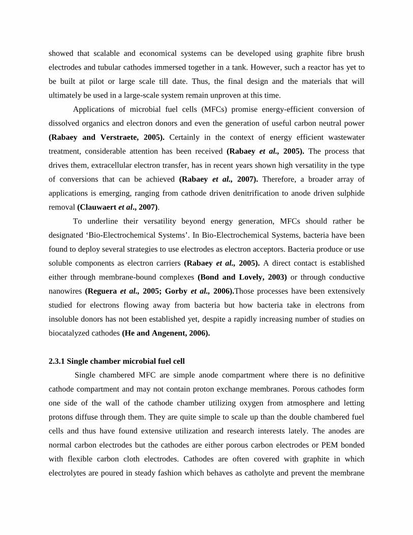
2.3.2 Dual chamber microbial fuel cell
Dual chamber microbial fuel cells can be of a variety of shapes such as U-shape with
cathode in one arm of the tube and anode being in the other arm. Both the electrodes are
separated by ion selective membrane such as proton exchange membrane that permits only
protons to pass through it and not to the solutions and microbes itself. The other common design
of dual chamber MFC use simple H- shaped assembly with anode in one side and cathode on the
other, both separated by proton exchange membrane.
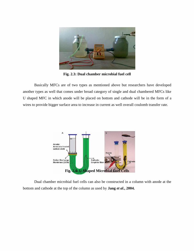
Fig. 2.3: Dual chamber microbial fuel cell
Basically MFCs are of two types as mentioned above but researchers have developed
another types as well that comes under broad category of single and dual chambered MFCs like
U shaped MFC in which anode will be placed on bottom and cathode will be in the form of a
wires to provide bigger surface area to increase in current as well overall coulomb transfer rate.
Fig. 2.4: U Shaped Microbial Fuel Cells
Dual chamber microbial fuel cells can also be constructed in a column with anode at the
bottom and cathode at the top of the column as used by Jang et al., 2004.

Fig. 2.5: Schematic diagram of mediator less and column shaped MFC designed by Jang et
al., 2004.
2.4 Difference between the single and double chamber MFC
The basic difference between the single and double chamber MFC is
The absence of membrane in single chamber MFC.
In the double chamber different conditions can be maintained in each compartment.
The rate of oxygen diffusion into the anode without an ion permeable membrane (single
chamber) is 2.7 times higher than the double chamber design.
Advantage of the single chamber MFC is the reduced set up costs, higher power output.

The disadvantage of single chamber MFC is the low coulombic efficiency generally
because of diffusion of oxygen into anode i.e. consumption of oxygen by the bacteria.
2.5 Microorganisms and Microbial Fuel Cell
Earlier it was thought only few microorganisms can be used to produce electricity. But
recently it was observed that most of the microorganisms can be utilized in MFCs. MFC concept
was demonstrated as early in 1910 where Escherechia coli and Saccharomyces sp. were used to
generate electricity using Platinum electrodes (Potter, 1911). Marine sediment, soil, wastewater,
freshwater sediment and activated sludge are all rich sources for the microorganisms (Niessen et
al., 2006; Zhang et al., 2006). Microorganisms survive and grow due to the energy they
generate by transferring electrons. During respiration, microorganisms liberate electrons from an
electron rich substrate at a low redox potential and transfer these electrons through a number of
electron transport complexes through the cell membrane where a final electron acceptor is
reduced.
Respiring microorganisms can use a large variety of different electron acceptors, ranging
from oxygen, nitrate, iron and manganese oxides to sulfate, but their ability to use the acceptor
with the highest redox potential will increase their energy for growth (Madigen et al., 2000) and
is their incentive to explore alternative electron acceptors. Microorganisms do not use the energy
produced by the flow of electrons in a direct way, the flow of electrons is used to create a proton
gradient across the cell membrane (Kim et al., 2003). The energy released by the inward flux of
the protons through a membrane complex (ATP synthase) is used to regenerate energy carrier
molecules such as adenosine triphosphates (ATP). By creating this proton gradient, the potential
difference between the electron donor (i.e. the substrate at low potential) and the electron
acceptor is translated into a process for the generation of energy (Logan, 2008). The higher the
potential difference between the electron donor and electron acceptor, the higher the proton
driven potential difference and the higher the potential amount of ATP which can be refuelled.
There are three categories of microbes that can be used in MFCs:
(a) Those that can directly transfer electrons to anode using anode as terminal electron
acceptor;
(b) Those that can’t directly but use mediators to transfer electrons to anode;
(c) Those who can accept electron from cathode.
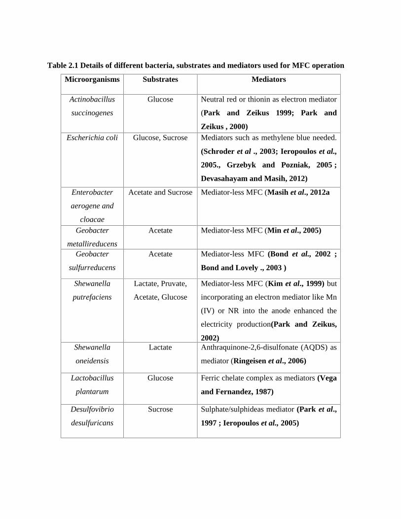
Table 2.1 Details of different bacteria, substrates and mediators used for MFC operation
Microorganisms Substrates Mediators
Actinobacillus
succinogenes
Glucose Neutral red or thionin as electron mediator
(Park and Zeikus 1999; Park and
Zeikus , 2000)Escherichia coli Glucose, Sucrose Mediators such as methylene blue needed.
(Schroder et al ., 2003; Ieropoulos et al.,
2005., Grzebyk and Pozniak, 2005 ;
Devasahayam and Masih, 2012)
Enterobacter
aerogene and
cloacae
Acetate and Sucrose Mediator-less MFC (Masih et al., 2012a
Geobacter
metallireducens
Acetate Mediator-less MFC (Min et al., 2005)
Geobacter
sulfurreducens
Acetate Mediator-less MFC (Bond et al., 2002 ;
Bond and Lovely ., 2003 )
Shewanella
putrefaciens
Lactate, Pruvate,
Acetate, Glucose
Mediator-less MFC (Kim et al., 1999) but
incorporating an electron mediator like Mn
(IV) or NR into the anode enhanced the
electricity production(Park and Zeikus,
2002)Shewanella
oneidensis
Lactate Anthraquinone-2,6-disulfonate (AQDS) as
mediator (Ringeisen et al., 2006)
Lactobacillus
plantarum
Glucose Ferric chelate complex as mediators (Vega
and Fernandez, 1987)
Desulfovibrio
desulfuricans
Sucrose Sulphate/sulphideas mediator (Park et al.,
1997 ; Ieropoulos et al., 2005)

Table 2.2: Details of different water samples used in MFC operations
S.No. Water Sample Power Density(mW/cm2)
CoulombicEfficiency (%)
References1 Chemical waste
Water24.33 61.11 VenkataMohan
et al., 20082 Designed
synthetic water11.50 62.5 VenkataMohan
et al., 20083 Primary treated
municipal wastewater
180.73 73.5 Masih et al.,2011
4 Domestic wastewater
0.0070 43 Min et al., 20085 Musi river 0.00066 ----- VenkataMohan
et al., 20096 Godavari river 0.00045 ----- VenkataMohan
et al., 20097 Starch
processingwastewater
0.0239 8 Lu et al., 20098 Swine
wastewater0.0261 8 Min et al., 2005
2.6 MFC Classification
One type generates electricity from the addition of artificial electrons shuttles to
accomplish electron transfer to the electrodes because most of the microbial cells are
electrochemically inactive. The electron transfer from microbial fuel cells to the
electrode is facilitated by mediators such as thionine, methyl viologen, methyl blue,
humic acid, neutral red and so on (Delaney et al., 1984).
Other type does not require this addition of exogenous chemicals and can be loosely
define mediator MFC. Mediator-less microbial fuel cells do not require a mediator but
uses electrochemically active bacteria to transfer electrons to the electrode (electrons are
carried directly from the bacterial respiratory enzyme to the electrode) (Kim et al., 1999;
Chaudhuri and Lovely, 2003). Some bacteria, which have pili on their external
membrane, are able to transfer their electron production via these pili.
Among the electrochemically active bacteria are Shewanella putrefaciens, (Kim et
al., 1999) Aeromonas hydrophila, and others. Geobacteraceae sulfurreducens (Bond and
Lovely, 2003),Geobacteraceae metalloreducens (Min et al., 2005) are all bioelectrochemically

active and can form a biofilm on the anode surface and transfer electrons directly by
conductance through the membrane and cathode acts as the final electron acceptor in the
dissimilatory respiratory chain of the microbes in the biofilm.
Biofilms forming on a cathode surface may also play an important role in electron
transfer between the microbes and the electrodes. G. metalloreducens and G. sulfurreducens
(Gregory et al., 2004) or other seawater biofilms (Bergel et al., 2005) may all act as final
electron donors. Since the cost of a mediator is eliminated, mediator-less MFCs are
advantageous in waste water treatment and power generation. Cathodes can serve as electron
donors for Thiobacillus ferroxidans suspended in a catholyte (Prasad et al., 2006) for an MFC
system that contained microbes in both anodic and cathodic chambers.
Mediator less MFCs can be consider to have more commercial potential then MFCs that
require mediators because the typical meditors are expansive and toxic to microorganism. This
same principle can be used to design both a dual chamber MFCs and single chamber MFCs
where the anode chamber is separated from the air cathode chamber by a gas diffusion layer
allowing for a passive oxygen transfer to the cathode eliminating the need for the energy
intensive air sparging of the liquid.
2.7 Electrode
The anode can be defined as the electrode at which electrons leave the cell and oxidation
occurs, and the cathode as the electrode at which electrons enter the cell and reduction occurs.
2.7.1 Anode
An anode are highly conductive, on corrosive, high specific surface area, non-foulting,
high porosity, inexpensive and easily made and scaled to large size the most important property
is different from other biofilm reactors is that the material must be electrically conductive like
carbon paper, cloth, foams, and RVC (Reticulated vitrified carbon). There are few direct
comparisons on the effect of these different carbonaceous materials on power generation. Recall
that if high internal resistance limits power generation, increasing anode surface area may not
appreciably affect power output, making it difficult to know if one material performed better
than another. In two chambered MFCs with equally-sized electrodes, it was found that an
increase in power could be observed when the anode size was increased relative to the cathode
only when the CEM size was substantially increased (Oh and Logan, 2006).
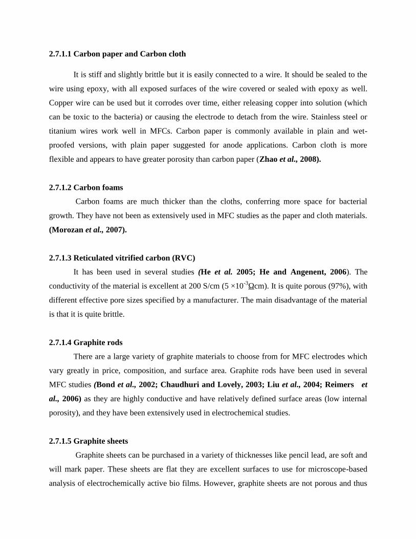
2.7.1.1 Carbon paper and Carbon cloth
It is stiff and slightly brittle but it is easily connected to a wire. It should be sealed to the
wire using epoxy, with all exposed surfaces of the wire covered or sealed with epoxy as well.
Copper wire can be used but it corrodes over time, either releasing copper into solution (which
can be toxic to the bacteria) or causing the electrode to detach from the wire. Stainless steel or
titanium wires work well in MFCs. Carbon paper is commonly available in plain and wet-
proofed versions, with plain paper suggested for anode applications. Carbon cloth is more
flexible and appears to have greater porosity than carbon paper (Zhao et al., 2008).
2.7.1.2 Carbon foams
Carbon foams are much thicker than the cloths, conferring more space for bacterial
growth. They have not been as extensively used in MFC studies as the paper and cloth materials.
(Morozan et al., 2007).
2.7.1.3 Reticulated vitrified carbon (RVC)
It has been used in several studies (He et al. 2005; He and Angenent, 2006). The
conductivity of the material is excellent at 200 S/cm (5 ×10⁻³Ωcm). It is quite porous (97%), with
different effective pore sizes specified by a manufacturer. The main disadvantage of the material
is that it is quite brittle.
2.7.1.4 Graphite rods
There are a large variety of graphite materials to choose from for MFC electrodes which
vary greatly in price, composition, and surface area. Graphite rods have been used in several
MFC studies (Bond et al., 2002; Chaudhuri and Lovely, 2003; Liu et al., 2004; Reimers et
al., 2006) as they are highly conductive and have relatively defined surface areas (low internal
porosity), and they have been extensively used in electrochemical studies.
2.7.1.5 Graphite sheets
Graphite sheets can be purchased in a variety of thicknesses like pencil lead, are soft and
will mark paper. These sheets are flat they are excellent surfaces to use for microscope-based
analysis of electrochemically active bio films. However, graphite sheets are not porous and thus
produce less power per geometric (projected) surface area than felts or foams but there porosity
can be induced by dipping them in saline solution and there active surface area can be increased
by making holes in it so that more number of microbes can be attached to it (VenkataMohan et
al., 2008; Masih et al., 2011).
Current densities using a graphite rod, graphite felt or graphite foam were compared and
found effective (Chaudhuri and Lovely, 2003). It was found that increasing the total accessible
geometrical (projected) surface area increased current generation by Rhodoferax Ferrireducens
in two-chamber, poised-potential MFCs.
2.7.1.6 Graphite granule
Graphite granules are chunks of graphite that resemble pencil lead in their appearance
and are available from many different sources (e.g., Graphite Sales, Inc., Chagrin Falls, OH).
The first use of these materials was reported by Rabaey et al. (2005) as an anode material, but
they have since been used in other packed-bed reactors as both anodes and cathodes (Aelterman
et al., 2006; Heilmann and Logan, 2006; Rabaey et al., 2006).
2.7.1.7 Graphite fibers and brushes
The highest specific surface areas and porosities form anodes can be achieved using
graphite fiber brush electrodes (Logan et al., 2007). These brushes can be made from carbon
fibers produced by different manufacturers using conventional industrial brush machines. The
core of the wire can be made from non-corrosive metal.
2.7.2 Cathode
The design of the cathode is the single greatest challenge for making an MFC a useful
and scalable technology. The chemical reaction that occurs at the cathode is difficult to engineer
as the electrons, protons and oxygen must all meet at a catalyst in a tri-phase reaction (solid
catalyst, air, and water). The catalyst must be on a conductive surface, but it must be exposed to
both water and air so that protons and electrons in these different phases can reach the same
point.

2.7.2.1 Carbon cathodes with Pt catalysts
The most commonly used material for a cathode is commercially available carbon paper
pre-loaded with a Pt catalyst on one side, available from different manufacturers (e.g., E-Tek,
USA, 0.35 mg-Pt/cm2). When used in the MFC, the side containing the catalyst faces the water,
with the uncoated side facing air. Catalyst binders, when the catalyst is applied to carbon it must
be held there using a material that allows transfer of protons, electrons and oxygen. Nafion is
therefore typically used due to its high proton conductivity and oxygen permeability. Other
materials such as polytetrafluoroethylene suspension (PTFE) can also be used (Cheng et al.,
2006) prepared Pt-based cathodes.
2.7.2.2 Carbon cathodes with non-Pt catalysts
Park and Zeikus (2002) first experimented with non-precious-metal, carbon-based air
cathodes in MFCs. They made ferric (Fe3+) cathodes by forming plates out of ferric sulfate (3%
w/w), fine graphite (60%), kaolin (36%, as a binder), and nickel chloride (1%) and baking at
1100°C for 12 h under N2 gas. These iron cathodes produced up to 3.8 times as much power as
plain woven graphite cathodes, but they were not compared to Pt-based cathodes of similar
dimensions (Park and Zeikus, 2003). Cathode performance equal to that of Pt-based carbon
cathodes has now been achieved using transition-metal carbon cathodes, thus eliminating the
need for precious metals in MFCs. Zhao et al., (2005) showed in electrochemical tests that two
different transition metal catalysts, iron phthalocyanine (FePc) or cobalt tetra methoxy
phenylporphyrin (cotmpp), could produce power at levels comparable to or better than those
achieved with Pt-based cathodes at current densities.
2.7.2.3 Plain carbon cathodes
The efficiency of a catalyst is often assessed by comparing current or power densities to
those with plain carbon electrodes of the same surface area. An oxygen reduction still proceeds
in the absence of the catalyst, but the rate is reduced. In general, current and power are reduced
by a factor of 10 or more with plain carbon materials. However, if the cathode surface area is
substantially increased, it is possible to achieve much higher power densities. Reimers et al.
(2006) tested sediment MFC that had 1-m long carbon brush cathodes the use of carbon brush
cathodes was first tested by Hasvold et al., 1997 with magnesium alloy anodes.

2.7.2.4 Tubular carbon-coated cathodes
MFCs require high surface areas and porosities typical of wastewater reactors. One new
approach to wastewater treatment has been to use tubular ultrafiltration membranes, providing
high surface areas for filtering the treated water. Based on that idea of high surface areas
provided by these membranes, Zuo et al. (2007) developed a tubular cathode by applying a
conductive graphite paint material to a hydrophilic tubular ultrafiltration membrane (polysulfone
membrane on a composite polyester carrier) that had an inner diameter of 14.4 mm (B0125, X-
FLOW) and wall thickness of 0.6 mm. The tubes were coated on the air-facing side with a
proprietary graphite paint to make the tube electrically conductive.
Apart from them same material even can be used in both anode and cathode and even
without plating material will provide sufficient electron flow by applying holes in electrodes
(Masih et al., 2011)
2.8 Membrane and separators
In MFC, a membrane is an essential component of the system as it separator and
provides a method for conducting protons between two gases .The membrane is therefore
referred to as a proton exchange membrane. Liu and Logan (2004) showed that an MFC lacking
a membrane produced more power than an MFC with the membrane (Nafion) bonded to the
cathode, indicating that the membrane can adversely effect power generation (Fig. 2.6).
2.8.1 Cation exchange membranes
The most commonly used cation exchange membrane (CEM) is Nafion 117 (Dupont
Corp.) available from Ion Power, Inc and there the code (117) is indicate the thickness of
membrane (0.019 cm) This membrane was developed for use in an HFC and thus was optimized
to create a stable and conductive environment for high proton concentrations under conditions
where the water content is carefully controlled. However, this material becomes completely
saturated with water in an MFC, producing a pH reflective of the solution properties. Thus, it
does not function according to its intended purpose in an MFC as it cannot operate under its
designed conditions.
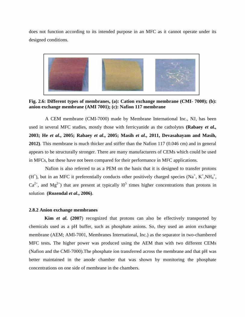
Fig. 2.6: Different types of membranes, (a): Cation exchange membrane (CMI- 7000); (b):anion exchange membrane (AMI 7001); (c): Nafion 117 membrane
A CEM membrane (CMI-7000) made by Membrane International Inc., NJ, has been
used in several MFC studies, mostly those with ferricyanide as the catholytes (Rabaey et al.,
2003; He et al., 2005; Rabaey et al., 2005; Masih et al., 2011, Devasahayam and Masih,
2012). This membrane is much thicker and stiffer than the Nafion 117 (0.046 cm) and in general
appears to be structurally stronger. There are many manufacturers of CEMs which could be used
in MFCs, but these have not been compared for their performance in MFC applications.
Nafion is also referred to as a PEM on the basis that it is designed to transfer protons
(H+), but in an MFC it preferentially conducts other positively charged species (Na+, K+,NH4+,
Ca2+, and Mg2+) that are present at typically l05 times higher concentrations than protons in
solution (Rozendal et al., 2006).
2.8.2 Anion exchange membranes
Kim et al. (2007) recognized that protons can also be effectively transported by
chemicals used as a pH buffer, such as phosphate anions. So, they used an anion exchange
membrane (AEM; AMI-7001, Membranes International, Inc.) as the separator in two-chambered
MFC tests. The higher power was produced using the AEM than with two different CEMs
(Nafion and the CMI-7000).The phosphate ion transferred across the membrane and that pH was
better maintained in the anode chamber that was shown by monitoring the phosphate
concentrations on one side of membrane in the chambers.

2.8.3 Bipolar membrane
A bipolar membrane consists of an anion and a cation membrane joined in series. As
voltage develops rather than protons passing the membrane water is split, resulting in the
transport of anions (OH-) to the anode and cations (H+) to the cathode to balance charge. The
energy needed for the water splitting reaction is claimed to be small because water is split into
ionic species, H+ and OH-. There also examined power output in a MFC with a salt bridge
instead of a membrane system. The low power output was directly attributed to the higher
internal resistance of the salt bridge system compared to that of the membrane system based on
measurements using impedance spectroscopy. In both systems, it was observed that oxygen
diffusion from the cathode chamber into the anode chamber was a factor in power generation
(Min et al., 2005). Ter Heijne et al. (2006) developed an MFC based on using a ferric iron
catholyte. Using a bipolar membrane, they were able to maintain the low pH in the cathode
chamber and near-neutral pH in the anode chamber.
2.9 Role of substrate in MFC
The production of current in an MFC is directly linked to the ability of bacteria to oxidize
a substrate and transfer electrons resulting from this oxidation to the cathode electrode. The
current and power density (PD), columbic efficiency (CE) and pollutants removal efficiencies
differ between the various studies according to the experimental conditions (initial wastewater
composition, concentration, and MFC set up conditions). Since there different types of substrate
that provide energy to the microbes and help them to degrade organic matter while producing
electricity. Substrate choice may be of two types: fermentable substrate and non fermentable
substrate. Study showed that fermentable substrates are less efficient than non fermentable
substrate while used in same set up of MFC (Masih et al., 2011; Masih et al., 2012a;
Devasahayam and Masih, 2012).
2.9.1 Sucrose
Sucrose was used as a fuel in a thionine-mediated microbial fuel cell containing Proteus
vulgaris serving as the biocatalyst in the anode compartment. In study sucrose of 0.4%
concentration in various water samples and pure microbial cultures of Enterobacter cloacae,

Enterobacter aerogene and E.coli has been used and showed voltage in the range of 700 mV
(Masih et al., 2011; Masih et al., 2012b; Devasahayam and Masih, 2012)
. The measured yields show that under suitable conditions the substrate may be oxidized
quantitatively to electricity and carbon dioxide (Bennetto et al., 1985). Since this process is
carried out in an anaerobic condition, carbon dioxide, protons and electrons are produced as
below:
Anodic reaction:
C12H22O11 + 13H2O → 12CO2 + 48H+ + 48e−…………….. (6)
Cathodic reaction:
O2 + 4e− + 4H+ → 2H2O………..…………......................... (7)
2.9.2 Cellulose
Cellulose is the most abundant biopolymer, and there is great interest in using this
chemical as a substrate in an MFC. However, use of a particulate substrate in an MFC has not
been well investigated. Cellulosic materials are desirable feedstocks for alternative fuels and
energy carriers such as ethanol, biodiesel, or hydrogen since they are renewable and abundant
(Mielenz, 2001; Powlson et al., 2005; Ni et al., 2006). Cellulose must first be hydrolyzed to a
soluble substrate that can be taken up by the cell. In previous MFC tests this has required the use
of enzymes to hydrolyze.
Since cellulose is substrates that cannot be directly utilized by bacteria it has to be
converted to monosaccharides. Microbes utilizing cellulose should be having cellolytic and
exoelectrogenic activities. Ren et al., 2007 used a culture of the cellulose fermentor Clostridium
cellulolyticum and the exoelectrogen Geobacter sulfurreducens to generate electricity in an MFC
fed with cellulose (Rezaei et al., 2009). Recently raw corn stover has been used for electricity
generation but its power generation capacity was found to be much lesser than that in the case of
glucose (Wang et al., 2009).
2.9.3 Acetate
Acetate is a mild acid and simple substrate and it is extensively used as carbon source to
induce electro active bacteria (Bond et al., 2002; Masih et al., 2012a,b). In order to benchmark

new MFC components, reactor designs or operational conditions, acetate is commonly used as a
substrate because of its inertness towards alternative microbial conversions (fermentations and
methanogenesis) at room temperature (Aelterman, 2009).Further, acetate is the end product of several metabolic pathways for higher order carbon
sources. Very recently, Chae et al. (2009) compared the performance of four different substrates
in terms of CE and power output. Acetate-fed MFC showed the highest CE (92%) (Masih et al.,
2012a), followed by butyrate (43.0%), propionate (36.0%) and glucose (15.0%).
Also, when acetate was compared with various wastewater samples as substrate in MFC,
the MFC based on acetate-induced consortia achieved more than 2-fold maximum electric
power, and one half of optimal external load resistance compared to the MFC based on consortia
induced by a protein-rich wastewater (Liu et al., 2009; Masih et al., 2011).When acetate is used
as a substrate the reactions occurring at the anode and cathode are as follows:
Anodic reaction:
CH3COO- + 2H2O 2CO2 +8 e- + 7H+………………........ (8)
Cathodic reaction:
4H+ +O2 + 4e- 2H2O…………………………...………….. (9)
2.9.4 Glucose
Bacteria that produce energy from substrate fermentation obtain energy by substrate level
phosphorylation, taking a substrate (such as glucose) and producing a variety of different end
products.
Typical fermentation conversion rates are -2 moles of hydrogen produced per mole of
glucose, with a maximum conversion of 4 mol/mol. This translates to approximately 17%
conversion of substrate to hydrogen, with a maximum of 67% conversion for glucose. Kim et
al., (2000) reported that the performance of a MFC containing Proteus vulgaris depended on the
carbon source in the initial medium of the microorganism and glucose initiated cells in MFC run
for a short time period compared with galactose. Rabaey et al., (2003) reported that a maximum
power density of 216 W/m3 was obtained from a glucose fed-batch MFC using 100 mM
ferriccyanide as cathode oxidant. Using glucose as an electron donor, 6.8 to 33 mW/m2 (graphite

rods, carbon felt or foam electrodes) was produced with a two-chamber system. Coulombic
efficiency was 83% with a poised potential working electrode and was 81% using ferricyanide at
the cathode. Fructose, sucrose, and xylose also produced power (Choudhary and Lovely, 2003).
The possibility of various reactions occurring in anode and cathode chambers of MFCs
with glucose as substrate considering complete oxidation are depicted in the following equations.
Anode : C6H12O6 + 6H2O → 6CO2 +24H+ + 24e- (10)
Aerated catholyte : nO2 + H+ +e- → H2O (11)
Ferricyanide catholyte : 4Fe(CN)63- + 4e- → 4Fe(CN)6
4- (12)
O2 + 4[Fe(CN)6]4- + 4H+ → [Fe(CN)6]3- + 2H2O (13)
A reactor inoculated with a river sediment using a low concentration of glucose and
glutamate produced an Alphaproteobacteria-dominated community (Phung et al., 2004).
Aelterman et al. (2006) examined the microbial community that developed over time in a six-
stack MFC fed glucose and using ferricyanide at the cathode. Zhang et al. (2007) also used
ferricyanide in a two-bottle type of MFC, producing 50 mW/m2 with a glucose substrate, and 70
mW/m2 with acetate. However, the finding of a coulombic efficiency of 96.8% by Geobacter
sulfurreducens seems unreasonably large, suggesting that either substrate had been accumulated
in the bacteria (Freguia et al., 2007). Devasahayam and Masih, 2012 used glucose with pure
culture of E.coli and yamuna river samples in dual chambered MFC and showed maximum
voltage of 779 mV and 463 mV respectively.
2.9.5 Synthetic wastewater
Synthetic wastewaters of much defined chemical composition and pH have been also
used. The wastewater was prepared by mixing Na2HPO4, NaH2PO4, KH2PO4, CuSO4, MnSO4,
MgSO4, and ZnSO4 etc. (VenkataMohan et al., 2008) has used different wastewater at different
loading rates to achieve performances.
Logan et al., 2009 have done an experiment in which they have used two different
synthetic wastewaters with the same organic pollutants (glucose and peptone) and same loading
rates. One was fed with readily biodegradable substrate and other with slowly degradable
substrate. The results of such experiments showed that MFC with slowly degradable waste was
more efficient in terms of electricity generation probably because of production of intermediates
that favors electricity generation.
2.9.6 Dye wastewater
Sun et al., 2009 have reported that electricity generation was affected by higher
concentrations of ABRX3 an azo dye. The probable reason for this was due to competition
between the azo dye and anode for the electrons from carbon sources.
2.9.6 Brewery wastewater
Because of the food derived nature of organic matter and lack of inhibitory substances in
the brewery it is considered to be a good source of electricity. Other properties of brewery
wastewater such as high carbohydrate content and low ammonium nitrogen concentration make
it an ideal substrate for MFC operation. However maximum power produced by brewery
wastewater was lower than that obtained with the domestic wastewater. This may be because of
differences in the conductivities of two solutions. Wen et al., 2009 has suggested that important
factors affecting the performance of brewery wastewater MFC are reaction kinetic loss and mass
transport loss.
2.9.7 Sunlight
A solar powered MFC was described by Cho et al. (2008) in which only Rhodobacter
sphaeroides (fed on succinate) was used as the anodic bacterium. The power output (790
mW/m2) in this case was dependent on both light and the nature of the nitrogen source. The plant
MFCs in rice paddy fields have been reported to produce electricity by rhizosphere populations
oxidizing organic carbon delivered to the rhizosphere (Kaku et al., 2008). Similar proof of
principle was also demonstrated using reed mannagrass (Glyceria maxima) and maximum power
of 67 mW/m2 anode surface was achieved (Strik et al., 2008a). Another type of phototrophic
MFC, a photosynthetic algal MFC was investigated (Strik et al., 2008b) which produced a
maximum power of 110 mW/m2 surface area of photobioreactor. The organic matter produced in
the algal photobioreactor via photosynthesis was supplied to a MFC for electricity generation.
2.9.8 Starch processing wastewater
Starch processing wastewater (SPW) contains a relatively high content of carbohydrates
(2300–3500 mg/L), sugars (0.65–1.18%), protein (0.12–0.15%) and starch (1500–2600 mg/L),

representing an important energy-rich resource, which can be potentially converted to a wide
variety of useful products (Jin et al., 1998) and was used as a fuel to enrich a microbial
consortium generating electricity and current generation (0.044 mA/cm2) was coupled to a fall in
COD from over 1700 mg/L to 50 mg/L in 6 weeks (Kim et al., 2004). Lu et al. (2009) operated
a MFC with SPW containing 4900 mg/L of COD over four cycles and obtained a maximum
voltage output and power density of 490.8 mV and 239.4 mW/m2 in the third cycle. However,
the CE was only 7%. They attributed this low CE to oxygen diffusion to the anode compartment
resulting in oxidization of other electron acceptors, biomass production and fermentation.
2.9.9 Inorganic and other substrates
Apart from these above mentioned substrates, some other substrates have also been
explored. Electricity generation with anodic sulfide oxidation was reported (Rabaey et al., 2006)
with a PD of 39 mW/ m2
Huang and Logan (2008) reported the effectiveness of electricity production with paper
recycling plant wastewater using MFC and obtained a maximum PD of 672 mW/m2 after
amending the wastewater with phosphate buffer. However, with unamended wastewater, the
power output was only 144 mW/m2 mainly due to low solution conductivity. The large amount
of wastewater produced in integrated biorefineries is also a potential source of energy
(Kaparaju et al., 2009). Recently the use of MFCs to remove the fermentation inhibitors in
cellulosic biorefineries including furfural, 5-hydroxymethylfurfural, vanillic acid, 4-
hydroxybenzaldehyde and 4 hydroxyacetophenone while simultaneously producing electricity
was demonstrated (Borole et al., 2009).
Some views that can be drawn are
1. Substrates being used in both MFCs have grown in complexity and strength (higher organic
loading rate). A complex substrate helps in establishing a diverse and electrochemically active
microbial community in the system while a simple substrate is easier to degrade and improves
the electric and hydrogen output of the system.
2. The output of these systems (electric current and electric power) is still some way from large-
scale applications. More technological advancements in terms of material, costs and substrates
being used are necessary to bring these systems at a level where they can be commercially
exploited.

3. Several new substrates hitherto exploited can be brought as substrates under the MFC set ups.
These may include the wastewaters from molasses based distilleries rich in organic matter and
produced in large volumes, wastewater from large number of biorefineries, wastewaters from
pharmaceutical industry with recalcitrant pollutants, waste plant biomass (agriculture residue)
which is burnt at this moment, etc.
4. The integration of MFCs with existing separation, conversion and treatment technologies is
probably the best option where in the effluent from one stream can be used as a feed for the other
one.
Table 2.3: Different substrates used in microbial fuel cells (MFCs) and the maximumcurrent produced
Type of
substrate
Conc. Source
inoculum
Type of MFC(with electrode
surface areaand/or cell
volume)
Currentdensity
(mA/cm2)at
maximumpower
Reference
Acetate 1 g/L Pre-acclimatedbacteria from
MFC
Cube shapedone-chamber
MFC withgraphite
fiber brush
anode (7170
m2/m3 brush
volume)
0.8 Logan et al.2007
Cellulose
particles
4 g/L Pure culture ofEnterobacter
cloacae
U-tube MFCwith carboncloth anode(1.13 cm2)
and carbon
fibers as
cathode
0.02 Rezaei et al.,2009
Glucose 6.7 mM Mixed bacterialculture
maintained onsodium acetate
for 1 year(Rhodococcus
and
Paracoccus)
One-chamberair-cathode
MFC (12 mL)with nonwet
proofed carboncloth as anode(2 cm2) and
wet proofed
carbon cloth as
cathode (7
cm2)
0.70 Catal et al.,2008
Lactate 18 mM Pure culture of S.oneidensis MR-
1
Two-chamberedMFC with
graphite feltelectrode
(20 cm2)
0.005 Manohar andMansfeld, 2009
Starch 10 g/L Pure culture ofClostridiumbutyricum
Two chamberedMFC withwoven graphiteanode
(7 cm2) and
ferricyanide
catholyte
1.3 Niessen etal.,2004
Sucrose 2674
mg/L
Anaerobicsludge fromsepticTank
Two-chamberedmediator-less
MFC withstainless steelmesh as anode(213.29 cm2)
and
cathode (176.45cm2); KMnO4
(0.2 g/L) ascatholyte
0.19 Behera andGhangrekar,
2009
2.10 Working mode of MFCs operation
MFCs can be operated in batch or continuous mode. A batch mode involves setting up
the MFC with desired substrate and allowing it to completion, followed by the manual addition
of more substrate. A continuous flow system that uses pumps to add more substrate and remove

wastes without manual interference. While operating a non mediated MFC in continuous mode
rather than batch, the power output decreased from 479W/m2 to 49W/m2. Although it cases a
decrease in power output, continuous flow MFCs has brooder possible application because they
require less maintenance (Rabaey et al., 2005).
The Continuous Flow Systems (CFS) is designed to easy treatment of a continuous
stream of wastewater. The unit is fully automated with the only operator intervention required
being the refilling of the flocculant and disposable media. Continuous process units range from 5
gpm to 40 gpm. Additional options are available for increased flocculation with pre-ozonation,
water purification with post-ozonation and increased efficiency of de-watering and drier cakes
(Rabaey et al., 2003).The system has a monitoring system that sounds an alarm when restocking
of media is required or when the treatment process is interrupted. Proven results for reduced
TDS/TSS levels lower residual heavy metals and lower cost per gallon treated using this
approach (Logan, 2008).
The Sequencing Batch Reactor (SBR) is an activated sludge process designed to operate
under non-steady state conditions. An SBR operates in a true batch mode with aeration and
sludge settlement both occurring in the same tank (Cheng et al., 2006). The major differences
between SBR and conventional continuous-flow, activated sludge system is that the SBR tank
carries out the functions of equalization aeration and sedimentation in a time sequence rather
than in the conventional space sequence of continuous-flow systems
(Logan et al., 2006).
In addition, the SBR system can be designed with the ability to treat a wide range of
influent volumes whereas the continuous system is based upon a fixed influent flow rate (Cheng
and Logan, 2007). Thus, there is a degree of flexibility associated with working in a time rather
than in a space sequence SBRs produce sludges with good settling properties providing the
influent wastewater is admitted into the aeration in a controlled manner. Controls range from a
simplified float and timer based system with color graphics using either flow proportional
aeration or dissolved oxygen controlled aeration to reduce aeration to reduce energy
consumption and enhance the selective pressures for BOD, nutrient removal, and control of
filaments (Kim et al., 2007). An appropriately designed SBR process is a unique combination of
equipment and software. Working with automated control reduces the number of operator skill
and attention requirement.
2.11 Effect of the external resistance in MFC
There are several different methods to evaluate the internal resistance of an MFC. These
include polarization slope, power density peak, electrochemical impedance spectroscopy (EIS)
using a Nyquist plot, and current interrupt methods. The microorganism oxidizing the substrate
release electrons onto the anode surface and should thus be considered a current. However, this
current source is not constant, but affected the amount of resistance in the system. There is not a
linear relationship between voltage and current in this case. The optimal resistance to be used in
each setup depends on numerous factors, including the application, substrate, inoculums, type of
reactor, and any potential losses within the system (Allen and Bennetto, 1993).
The lower current production means that some electrons are consumed by mechanism
other than the cathode reaction (Kim et al., 2003). Gil et al. (2003) or oxygen diffused from
cathode compartment or dissolved oxygen present in the influent. At low resistance the electrons
move more easily through the external circuit than at high resistance, oxidizing electron carriers
of the microbes in the anode. Higher fuel oxidation by the microbes is expected with high ratio
of oxidized electron carriers of the culture at a low resistance to remove organic contaminants at
a high rate (Jang et al., 2004). It was observed that at lower external resistance the current
production is higher and vice versa (Logan, 2008). Even for same waste water COD
concentration the production of current is decreases due to increase in resistance. At same time
COD concentration when resistance was increased, the production of current decreased. This
shows that the resistance becomes the rate-limiting step. Even at lower resistance, low current
production could be attributed to the lower electron consumption rate at the cathode than transfer
rate from the external circuit. This might be due to limited supply of proton or oxygen but at this
point it is not known how this is possible. It is plausible that under the conditions of limited
electron disposal through the circuit with a high resistance, the electrons are consumed in the
anode to reduce other electron acceptors such as sulfate and nitrate.
2.12 Electrical Parameter
2.12.1 Open circuit voltage
Open circuit voltage is the voltage measured in the absence of any resistor. By definition
it is the difference of electrical potential between the two electrodes i.e. anode and cathode of a

cell in the absence of any resistor. Theoretically open circuit voltage should be almost close to
the electromotive force of a cell but in practice it does not happen generally. The probable reason
for this disparity between the two is the large energy losses at the cathode, which is called the
over potential. Over potential is directly related to current density and generally includes:
2.12.2 Activation losses
To carry out the oxidation-reduction reaction at the electrode bacteria need to cross an
energy barrier that results in large activation losses. But increasing the electrode surface area can
minimize this loss. Other measures taken to overcome this loss are increasing temperature and by
enrichment of biofilm on the anode surface (Logan et al., 2006).
2.12.3 Metabolic losses
Metabolic loss during MFC operations is another important electrical parameter that
affects the efficiency of the working model. This is because of the large difference of redox
potential between the substrate and anode (Logan et al., 2006).
2.12.4 Concentration losses
These occur at the high current density and are due to rate of mass transport of a species
to or from the electrode and these losses limit the current production. (Larminie, 2000).
2.12.5 Ohmic losses
Impedence to the flow of electrons at the electrodes and interconnections and to the
protons at the membrane and electrolytes is the cause of these losses. Keeping the electrodes in
close proximity to each other i.e. at the closest distance and using the electrolytes of higher
conductivity can overcome these losses (Hoogers, 2003).
2.12.6 Power and power density
Power can be calculated as
P =E2cell/ Rext………………………… (14)

where Ecell / Rext is calculated by Ohm’law. Thus power density is calculated as amount of
power per unit surface area of the electrode. To enhance power density it is preferred to use
anode with the projected surface area. Surface area of anode can be enhanced greatly by using
porous electrodes. Other measures are using electrodes in sieve or brush form but in these cases
it is difficult to measure surface area of each and every unit of the anode. Therefore using porous
anode with defined surface area of the plate and of each pore as well is advantageous over others.
2.12.7 Polarization curve
In microbial fuel cells the highest voltage is achieved at open circuit condition and the
voltage drop off with increasing current draw. This is known as polarization and is represented as
polarization curve. In other words in polarization curve voltage is represented as function of
current. (Logan et al., 2006).
The three basic regions affecting the overall polarization in a polarization curve are:
Fig 2.7 (a) - Polarization curve- relation between power and current.
Fig. 2.7(b)- Polarization curve- relation between voltage and current
2.13 Coulombic efficiency
Coulombic efficiency is the efficiency with which electrons are transferred in a system to
carry out an electrochemical reaction. This is an important measure of the microbial fuel cell
efficiency as it measures the number of coulombs recovered as electrical current. The coulombic
efficiency is dependent on two major factors firstly it depends on microorganism carrying out the
electrochemical reaction and secondly the substrate used by the bacteria to generate current (Lee
et al., 2008).
Coulombic efficiency of the system is thus directly associated with the chemical oxygen
demand of the anode solution at the start of the operation and at the end of the operation as well.
This can be represented by simple formula:
(Cs-Co/CS) 100 ………………………… (15)
Where Cs is the initial value of chemical oxygen demand and Co is the final value of
chemical oxygen demand.
The possible relation between the chemical oxygen demand and coulombic efficiency of
the system can be cited as- at the start of the process when bacteria are at rest and reaction has
not commenced, the system contain maximum amount of chemicals dissolved in it. The results
of experiments using wastewater as a substrate show a higher coulombic efficiency (Rabaey et
al., 2003). As the reaction starts; bacteria begin to decompose the complex organic substrates
into simpler form and CO2. For attainment of the maximum amount of energy derived from the
system the substrate must be completely oxidized to CO2 with efficient transfer of electrons to
the electrodes. In the absence of complete oxidation a significant portion of the energy may lost
in the form of unoxidized substrate. The maximum coulombic efficiency obtained with complete
oxidation of substrate using Geothrix fermentans is about 94%. (Bond and Lovely, 2005).
2.14 Applications of MFC
Until now discussion has primarily centered on the use of MFCs for either wastewater treatment
or as a method of renewable energy production in the form of electricity or hydrogen. However,
MFCs have been examined for two other applications that will be examined in this chapter. The
first one is using the MFC as a remote source of power. Reimers et al. (2001) first developed
this new concept of a sediment MFC (SMFC) and
showed that power generation could be sustained by bacteria using only the organic matter in the
sediment. Since then, there have been improvements in power output through modification of the
materials, but also in the development of enhanced SMFCs through augmentation of the anode
with additional sources of energy. The second novel application of the MFC is as a method of
bioremediation. Remediation can include both degradation of organic pollutants at the anode as
well as reduction of inorganic chemicals such as nitrate or uranium at the cathode.
2.14.1 Electricity generation
MFCs are capable of converting the chemical energy stored in the chemical compounds
in a biomass to electrical energy with the aid of microorganisms. MFCs themselves can serve as
distributed power systems for local uses, especially in underdeveloped regions of the world.
MFCs are viewed by some researchers as a perfect energy supply candidate for Gastrobots by
self-feeding the biomass collected by themselves (Wilkinson, 2000). Because chemical energy
from the oxidization of fuel molecules is converted directly into electricity instead of heat, the
carnot cycle with a limited thermal efficiency is avoided and theoretically a much higher
conversion efficiency can be achieved (70%) just like conventional chemical fuel cells.
Chaudhury and Lovely (2003) reported that R. ferrireducens could generate electricity with an
electron yield as high as 80%. Higher electron recovery as electricity of up to 89% was also
reported (Rabaey et al., 2003).
However, MFC power generation is still very low (Tender et al., 2002; Delong and
Chandler, 2002), that is the rate of electron abstraction is very low. One feasible way to solve
this problem is to store the electricity in rechargeable devices and then distribute the electricity to
end-users (Ieropoulos et al., 2003). Capacitors were used in their biologically inspired robots
named EcoBot I to accumulate the energy generated by the MFCs and worked in a pulsed
manner. MFCs are especially suitable for powering small telemetry systems and wireless sensors
that have only low power requirements to transmit signals such as temperature to receivers in
remote locations (Ieropoulos et al., 2005; Shantaram et al., 2005).

2.14.2 Biohydrogen generation
MFCs can be readily modified to produce hydrogen instead of electricity. Under normal
operating conditions, protons released by the anodic reaction migrate to the cathode to combine
with oxygen to form water. Hydrogen generation from the protons and the electrons produced by
the metabolism of microbes in an MFC is thermodynamically unfavorable. Liu et al. (2005)
applied an external potential to increase the cathode potential in a MFC circuit and thus
overcame the thermodynamic barrier. In this mode, protons and electrons produced by the anodic
reaction are combined at the cathode to form hydrogen. The required external potential for an
MFC is theoretically 110 mV, much lower than the 1210 mV required for direct electrolysis of
water at neutral pH because some energy comes from the biomass oxidation process in the
anodic chamber. MFCs can potentially produce about 8–9 mol H2/mol glucose compared to the
typical 4 mol H2/mol glucose achieved in conventional fermentation (Liu et al., 2005).
In biohydrogen production using MFCs, oxygen is no longer needed in the cathodic
chamber. Thus, MFC efficiencies improve because oxygen leak to the anodic chamber is no
longer an issue. Another advantage is that hydrogen can be accumulated and stored for later
usage to overcome the inherent low power feature of the MFCs. Therefore, MFCs provide a
renewable hydrogen source that can contribute to the overall hydrogen demand in a hydrogen
economy (Holzman, 2005).
2.14.3 Waste water treatment
The high energy requirement of conventional sewage treatment systems are demanding
for the alternative treatment technology which will be cost effective and require less energy for
its efficient operation. In past two decades, high rate anaerobic processes are finding increasing
application for the treatment of domestic as well as industrial wastewaters. The major advantages
these systems offer over conventional aerobic treatment are no energy requirement for oxygen
supply, less sludge production, and recovery of methane gas. While treating sewage, particularly
in small capacity treatment plant recovery of methane may not be attractive, because most of the
methane produced in the reactor is lost through effluent of the reactor. The methane
concentration of about 16 mg/L (equivalent COD 64 mg/L) is expected in the effluent of the
reactor due to high partial pressure of methane gas inside the reactor (Adrianus and Lettinga,
1994). Hence, while treating low strength wastewater major fraction of the methane gas may be

lost through effluents, reducing the energy recovery. In addition, due to global environmental
concerns and energy insecurity, there is emergent interest to find out sustainable and clean
energy source with minimal or zero use of hydrocarbons.
Until now discussion has primarily centered on the use of MFCs for either wastewater
treatment or as a method of renewable energy production in the form of electricity or hydrogen.
Unlike conventional processes it can completely break down most of the acetate and carbon
compounds to CO2 and water. Some of the species used in MFCs can also utilize the sulphides
and other forms of sulphur compounds. The upflow mode MFCs and Single chambered like
constructions are favoured because of large scale implementation. (Jang et al., 2004).
Despite the potential of the MFC as a method of wastewater treatment, most researchers
have chosen to work with defined compounds such as glucose or acetate. Using these
compounds is necessary to understand the response of the system uncomplicated by the
variations in wastewater. However, most of the organic matter in waste water is protein, and the
bulk of the material is poorly defined and will likely remain so. Much more work is needed on
actual wastewaters in order to better understand how designs will function when given the
complex and particle laden waters. We need to focus on reactor factors that govern the cost of
treatment systems, such as hydraulic and solids retention times (HRTs and SRTs), the mass of
biomass produced and its settleability or filterability in engineered systems, and the impact of
recycle streams on system performance. More information is needed on the flow of nutrients,
such as nitrogen and phosphorous in the system, and methods to control these in MFC-based
systems. Pilot reactors need to be designed and tested so that we can be more realistic data on
system performance. The potential for system failure due to biofouling or loss of conductivity of
the medium need to be explored with materials considered for use in the system. As the MFC is
inherently an anaerobic process, we need additional information
on how to control the community to shift it towards electrogenesis, and away from sulfate
reduction and methanogenesis.
In industrial applications, it may be possible to better control the types of bacteria in
a process or even use pure cultures. In all systems, we need better information on the
microorganisms that can function as exoelectrogens. What are the most useful strains, and which
bacteria can produce the most power for us? How can we manipulate these strains for efficient
cellulose degradation and maximize hydrogen recovery in an MEC or BEAMR process? How

thick can a biofilm become before it is no longer useful as a method of electricity generation, and
what signals trigger nanowire production in cells? Is there a natural evolution of bacteria in an
electrogenic biofilm, and, if so, what controls that and what bacteria emerge as the “winners”?
Clearly, there is much exciting work to be done on better understanding the bacteria that function
within an electrogenic biofilm and that help us to harvest electricity from MFCs.
