rev 13 to isi-t-200.0, 'sses unit 2 isi program plan for
TRANSCRIPT

~ 0 1 0 ) ~
~ a j I ~ ~ ~
I I I
~ ~ ~
I ~ ~ ~
~ ~ ~ I
RR ~'
~
~ ~ ~ ~ ~ ~
~ ~
~ ~
~ I ' ~
~ ~'
~ ~
~ I ~
I '
~ ~ e0 t
C
~ ~


~ a
~ ~
~ o 0 0
I ~ ~
''~ . ~ I' ~
I'o~ ~
~ )
~ g
~ ~
~ ~
~ g
I ~ 'I
~ g
~ . ~
~ ~
~ g

~ ~
~ g
~ g
~ s
~ g
~ g
I ~ ~
~ ~
I ~ ~
'e
I ~ 'o
I'oI'e
~ ~
~ g
~ g
I
I'eI'
~ ~
~ g
~ g
I's
I ~


~ o
I'o~ ~
I'oI ~
I'o~ o
I'o~ ~ I 'o
~ r
~ o
I'o~ o

ol
I ~~
I'o~ g
~ ~
~ ~~ g
~ g
~ ~ I ~ ~
~~ I I I
I 4 ~
~ 4
~ g
~ y
I ~
I ~ '
~ g
~ a
,C


~~
I ~ 'o
I ~ o
~ ~~ ~
I ~ 'o
~ ~
~ ~
~ ~ I'o~ I ~ ~
I'oI ~ 'o
~ o I ~
' o
~~
~ ~
I ~ ~
~ ~ I ~ ~
~ o
o ~
~ ~
~ ~
I ~
lo 'o
I'oI 'o
I ~ I'oI'o
~ ~

~ >
~ I I ~
~ ~
~ >
~ >
I'oI'
I ~ 'o
I > ~~
I ~ I ~ 'o
I's~ >
~ >
~ >
~ ~
~ ~
~, ~ I's~ ~
~ . ~ I ~ >
~ ~
~ ~


o, ~ I '
lo I'o~
~ lo
~ I ~ o
~ . ~ I ~ ~ ~
~ I ~ ~ ~
~ o
I ~ 'o
I ~ 'o
~ ~
o ~
I ~ ~
I'oI'o
~ ~
I'oI oo
~ ~
~ ~ ~ o
~, ~ ~ ~ o
~ . ~ ~ I
~ ~ ~ o
~ . ~ ~ I ~ 'o
~ ~ I I'o~ ~ I I ~ 'o
~ ~
~ ~ ~ g
~ ~ ~ ~
~ ~ I ~ ~
~ ~ I'o~ ~ I ~
I ~ 'o
~ ~ I ~~ ~
~ ~ I ~
~ ~ ~ a
~ g
~ ~ ~ g
~ g
~ ~ I ~ ~
~ ~ ~ ~
~ ~ I'o~ ~
~ ~ ~
I ~ 'o
~ ~ ~
I ~
~ ~ I ~
~, ~ I ~ 'o
~ ~
I'o~ ~ I ~
~
~ ~ I'e~ ~ I II~ ~ I 'o
~ ~ ~ ~

~, ~ ~ I 's
~ ~
~ ~ ~ ~
~ ~ I's~ ~ I'~ ~ I ~ ~
~ ~
~ ~ I ~ ~
~~
~ ~ ~
~~
~ t ~l I ~ ~
~ ~~ ~ ~ I '
~ ~ I ~ ~
~, ~ ~ I I ~ ~
~~
~ ~ I
~~
~ ~
~~
~ ~ ~ ~
~ ~~ ~ I's~ ~ I 'o
~ ~ I '
~ ~ I 'o
~ ~

ISI-T-200.0
SUSQUEHANNA STEAM ELECTRIC STATION UNIT2
PUMP AND VALVEINSERVICE'INSPECTIONTESTING PROGRAM
PROGRAM SUMMARY
The pump and valve ISI testing program at the Susquehanna SES Unit 1 will be conducted inaccordance with the 1989 Edition of Section XI of the ASME Boiler and Pressure Vessel Code.ASME/ANSI OM Standard Part 6 and Part 10 of OMa-1988 are incorporated by reference. Theseare the latest ASME Code editions/addenda endorsed by 10CFR50.55{a)(f), "Inservice TestingRequirements". Specific exceptions &om these requirements are included here as Relief Requests,as allowed per 10CFR50.55a(fj(5)(iii). The second 10 year interval of the program commences onJune 01, 1994, as established by PP&L Letter PLA-3746, dated 4/09/92.
Pumps within the scope of this program are listed in the Pump Table, with pertinent data. Valveswithin the scope of this program are listed in the Valve Tables, organized by P &IDnumber, alongwith their pertinent data. A legend is provided for the explanation of column headings, assignedcodes, and other terminology employed in each table.
For valves so equipped, remote position indicators willbe utilized to demonstrate valve operability.Proper functioning of these position indicators willbe demonstrated at least once every 24 months.Safety valve and relief valve pressure setpoint testing will be conducted in compliance withASME/ANSIOM Standard Part 1 ofOM-1987.
With the exception ofvalves providing a high pressure to low pressure boundary (pressure isolationfunction), valve leakage rate testing and acceptance criteria for containment isolation valves willbebased on 10CFR50 Appendix J requirements as discussed in FSAR Subsection 6.2.6 andSusquehanna SES Technical Specification 3/4.6.1.2. Susquehanna was given permission in July1996 to implement Appendix J, Option B. The Valve Tables in this Program Plan may indicate a2Y or RF frequency, although testing frequencies for Appendix J leakage tests are actually based onthe &equency determined by the Appendix J, Option 8 program.
Testing procedures performed to satisfy Inservice Testing requirements are written, performed anddispositioned in accordance with the Surveillance Testing Program.
Check valves whose safety function is to open willbe full-stroke tested. Since disc position usuallyis not observable, verification of the safety analysis design flowrate through the valve is consideredan adequate demonstration of the full-stroke requirement. This convention is in agreement withNRC Generic Letter 89-04, Position l.
e2D-1
Rev. 13
02/98
ISI-T-200.0
Check valves that are not capable ofbeing full-stroke tested willbe disassembled and inspected perthe guidelines in Generic Letter 89-04, Position 2. All Generic Letter 89-04 check valves aredocumented in specific Relief Requests in this Program Plan. Generic Letter 89-04 established thata sample inspection plan for groups of up to four identical valves in similar applications may beemployed within the NRC guidelines specified in Position 2. The response to NUREG-1482Comment 4.1-3 states that it is acceptable to group valves &om multiple units ifthe two units are"identical", ifthe units willbe subjected to the same service conditions, and ifthe valves otherwisemeet the grouping criteria. Those groupings that utilize valves &om both units are designated in theRelief Request text. The frequency of testing is specified as one valve to be disassembed andinspected once every "refuel cycle combination". A refuel cycle combination is the time &arne&om the start of a Unit 1 Outage to the completion of the subsequent Unit 2 Outage. An example
'f
a refuel cycle combination was the Unit 1 9RIO (Fall 1996) and Unit 2 8RIO (Spring 1997).
Limit stroke times for power operated valves are provided and controlled in a general plantprocedure in accordance with the NRC guidance provided by "Minutes of the Public Meetings onGeneric Letter 89-04" (NRC Response to Question 38). Limit stroke times for power operatedvalves are calculated from the stroke time reference values in Engineering Specification M-1437 forUnit 2 valves.
Where devices monitoring appropriate parameters exist, permanently installed instrumentation willbe used during pump performance testing. Both permanent plant instrumentation and measuringand test equipment will be maintained by the Instrumentation and Controls Section in accordancewith their administrative procedures.
For those requirements of the Code which are impractical to test, Relief Requests have beenincluded in the program, as allowed per 10CFR50.55a(f)(5)(iii). These Relief Requests provide theimpractical test requirement, basis for relief and the proposed alternative testing. To explain thetesting of valves impractical to test at quarterly frequency, Cold Shutdown Test Justifications andRefueling Outage Test Justifications have been included in the program, per OMa-1988 Part 10,paragraphs 4.2.1.2 and 4.3.2.2.
2D-2Rev. 13
02/98

C l IP
~ ~
~ ~ I ~
~ ~ ~ ~ ~ ~
~~
~ ~ ~ I ~
~ I I ~
~ ~ ~' '
~
~'
~ ~
~ ~
~ o
~ ~
~ . ~ I ~ ~ ~ e
~ ~ ~ ~ ~
~ ~
~ I
~ ~ ~ ~ ~ ~ ~ ~ ~ ~
~'
~, + e ~
~ .. ~~
~ ~~ ~ ~ ~ ~ ~
~ ~
~ o ~ ~ ~ ~
~ I ~
r ~ ~ ~ ~ ~
~ ~ ~
I I I '~
r i ~
'~ ~
~ ~ ~ ~ ~
~ I ~ ~
~ ~ ~
~ e ~
~ ~

MAINSTEAM M-2101 Sheet 1&3
ValveNumber
fhCP
CttC'aO
00
OOC
C/7
g
1O
aO
.ga8O
0C4
O8i4
C0
0
~V
CO
80
0
Remarks.
HV-20107
HV-20109
HV-20111
G-3
E-1
F-1
2 B
2 B
2 B
GB
GT
GT
MO X
MO X
MO X
FSSTPI
FSSTPI
FS
STPI
FSSTPI
FSSTPI
CSCS
2Y
CS
CS2Y
CS
CS
2Y
Sheet 3
Sheet 1
Sheet 1

A
l%8HHHI5Ã8I%l%I%lSMM" l8Ãl%$55I555%ISW1%Ãl~~
l5ÃlSH&5%55%55&WW~~lSHlRSRIISWRRRI%lSI%~~
o ~ I '. '
t I
I

~, ~~ ~ I
~ ~

0

~ ~

I
sl
ol j ~
1

NUCLEAR BOILER M-2141 Sheet 1 Continued
Valve,,-'.
Number =COCP
:—j-—Q ==N= =
CC=-O
LsOCO
COCOC7,'oaC
Och
','l
.
O
O
O0
~Cl
pR
I
™
HV-241F019
HV-241F020
HV-241F021
HV-241F022A
E-7
E-8
C-5
I A
2 B
S B
I A 26
GT
GB
GB
GB
MO
MO
MO
AO
X 0/C
X 0
X 0
X C
FSSTPIU
FS
STPI
FS
STPI
FSSTPILJ
FSSTPIU
FSSTPI
FS
STPI
FSSTPILJ
2Y2Y
CSCS2Y
CSCS2Y
00
2Y2Y
RR32RR32
HV-241F022B F-5 I A 26 GB AO X C FSSTPILJ
FS
STPILJ
00
2Y2Y
RR32RR32
Q ZpeCD

IS I-T-200.0
THIS PAGE INTENTIONALLYLEFTBLANS:
2VT<1 Rev. 1302/98

REACTOR RECIRCULATIONM-2143 Sheet 1
Valve" — Nuinber
54
'H
0OCO
O
8O
0O
'.:O '-
0$cc
-'~~5
t
J
..;.",;: Rema'rks.
HV-243F019
HV-243F020
HV-243F031A
HV-243F031 B
HV-243F032A
B4 1
B4 1
F-8 1
F-8 1
F4 1
B
B
B
A 3/4 GB
A 1 GB
A 28 GT
A 4 GT
AO X
AO X
MO X
MO X
MO X
FSSTPILJ
FSSTPILJ
FSSTPI
FSSTPI
FSSTPI
FSSTPILJ
FSSTPI
FSSTPI
FSSTPI
FSSTPI
2Y2Y
2Y2Y
CSCS2Y
CSCS
2Y
2Y
Rapid acting valve.
O+gcy ~

REACTOR CORE ISOLATIONCOOLING M-2I49 (Continued)
ValveNumber
C5C'aOO
OCOO
0
a8.O
808
O
O,
~Cl
CO
; =- — Remarks
CllCO
HV-249%62
HV-249FOS4
F4
F-3
A A
A A
GT MO
GT MO X
0/C
0/C
FSSTPILJ
FSSTPILJ
FSSTPILJ
FSSTPILJ
2Y2Y
2Y2Y
HV-249FO)8 C-3 A A GB AO 0/C FSSTPILJ
FSSTPILJ
2Y2Y
XV-249F044A A-3 C A XC SA FS
PIFSPI
RF2Y
XV-249F044B D4 C A XC SA FS
PIFSPI
RF2Y

RESIDUALHEAT REMOVALM-2151 Sheet 2
ValveNumber
Eh
.9ONM
g
O
o8taO
O0Cl0Ia
O
On
~ClClM
O
g
8Q
O
Remarks
HV-251F003A
HV-251F011A
HV-251F047A
F-5 2 B A 20 GT
H-6 2 A P 4 GT
C-8 2 B A 20 GT
MO X OIC
MA X C
MO X 0/C
FSSTPI
FSSTPI
FSSTPI
LJ
FSSTPI
2Y
2Y
2Y
Disabled.
HV-251F103A C-3 2 A A I GB MO X C FSSTPILJ
FSSTPILJ
2Y2Y
PS V-25106A F-3 2 A,C A 3/4 RV SA 0/C RVLJ
RVLJ
RV2Y
SV-251 F079A G4 2 B A 1 GB SO X OIC FSSTPI
FS
STPI
2Y
Rapid acting valve.
SV-251F080A G-5 2 B A I GB SO X OIC FSSTPI
FS
STPI
2Y
Rapid acting valve.

t ~ II
tl
ISWRSEHSRSHRRRSIRRRWW ~
RWWQRQ@5k@ISISRI&WI . I I I
I'I

~ ~ ~ ~
'

~ ~ ~ ~ ~ ~
5 55 5555555WWel 1 ~ '
ol ~ ' ~
55555555555RIWH~ \ ~

~ ~ ~ ~ ~
~ ~ ~ I
I ~
. ~ ~, I

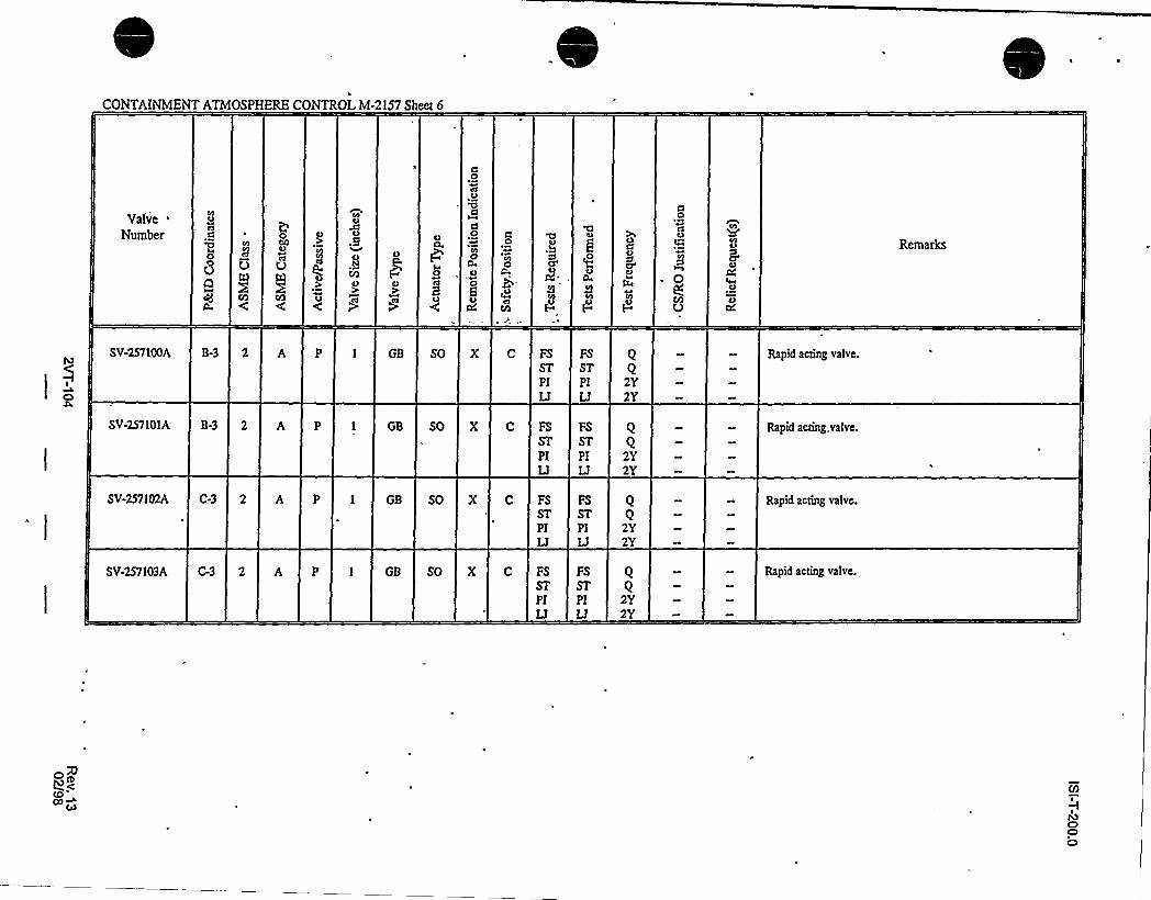
CONTAINMENTATMOSPHERE CONTROL M-2157 Sheet 1 Continued
ValveNumber
UC5C'oOOO0
&O
CO
.g
8tcO
On'
OIa
SC
AO''
~V
tO
r
cC
cdB
'C,O'O
Ot
0g0
Remarks
SV-25738 G-6 2 A A GB SO X C FSSTPILJ
FSSTPILJ
2Y
Rapid acting valve.
SV-25740A B4 2 A A GB SO X C FSSTPILJ
FSSTPILJ
2Y
Rapid acting valve.
SV-25740B B-5 2 A A GB SO C FSSTPILJ
FSSTPILJ
2Y
Rapid acting valve.
SV-25742A B-3 2 A A GB SO X C FSSTPILJ
FS
STPILJ
2Y
Rapid acting valve.
(0
MC)C)O

~ ~ ~ ~ ~ ~
I ~
t ~
~ ~, ~


~ ~ ~ ~ ~ ~
0 ~

~ ~ ~ ~ 1 I
~ t ~ ~
~ ~

~ ~ ~
~ ~
~ ~


~ ~ ~ ~ ~ ~
~ ~
~ ~
~ I
~ ~
~ ' ~ '
~ ~
~ ~ I
~ ~ ~ ~


r
I ' ~ '
tl . t ~
I
II I

~ ~ l ~ ~ ~
~ ~ . ~
4 I
I
I0
. ~ I
~ I
I ~

~ ~ ~ ~ ~ ~ I
~ I
~ ~
. I I t l
I ~
e
.IC'
I

ISI-T-200.0
REFUELING OUTAGE TK<ST JUSTIFICATIONNUMBER 02 (Cont'd.)
operation and is oAen maintained inert throughout cold shutdowns.Operation of the equipment serviced by these valves (ADS function of thesafety/relief valves) would not verify their proper opening since theaccumulators at the SRV operators provide capacity for several lifts.Performing any SRV liAs in an attempt to verify check valve openingwould increase the potential for SRV leakage or failure to reseat, wouldimpact proper maintenance of reactor pressure control during poweroperations, and would have the potential for degradation of the ADSfunction. For those reasons, no ADS SRV's are exercised during poweroperations nor during any cold shutdowns.
Valve closure is demonstrated by completion of leak rate testingperformed once per refueling cycle. Verification of the openingcapability of valves 226152 and 226154 will also be performed at thattime with an air pressure applied through the outboard test valves(226021, 226031), opening the inboard test valves (226155, 226153), todemonstrate passage ofmaximum accident condition flow.
2RJ02-2Rev. 13
02/9S

REFUELING OUTAGE TEST JUSTIFICATIONNUMBER 08
S-T-200.0
REFUELING OUTAGE TEST JUSTIIICATIONHAS BEEN 8'ITHDR4WN
2RJ08-1Rev. 13
02/98

ISI-T-200.0
REFUELING OUTAGE TEST JUSTIFICATIONNUMBER 13
System:
PEcID:
Valves:
Category:
Class:
Reactor Core Isolation Cooling
M-2149
249F028, 249F040
A,C
Function: Containment Isolation
Impractical Test Requirement: Exercise valve once per 92 days.
Basis for Deferment: These check valves are not equipped with position indication and systemdesign does not provide any practical method of verifying closure otherthan pressurization similar to leak rate testing. Such testing requiresinstallation of temporary equipment which is imprhctical on a quarterlybasis, and it would render the RCIC system inoperable during the testingperiod. While RCIC'is not an ECCS system, it is important to safety andcan provide an additional margin for prevention or mitigation of reactortransients. Normally, testing of this type is accomplished by'equir'edcontainment local leak rate testing in accordance with 10CFR50,Appendix J. More frequent performance represents an unnecessaryburden on the licensee.
Demonstrate closure by completion of leak rate testing performed onceper refueling cycle.
2RJ13-1Rev. 13
02/98

ISI-T-200.0
REFUELING OUTAGE< TE<ST JUSTIFICATIONNUMBE<R 14
System: Reactor Core Isolation Cooling
P8cID: M-2149
Valves: 249F063, 249F064
Category:
Class:
Function: Vacuum Breaker
Impractical Test Requirement: Exercise valve once per 92 days.
Basis for Deferment: These vacuum breakers installed on the RCIC turbine exhaust line are
not provided with position indication equipment nor is there pressureindication installed that would provide positive verification of valveoperation. A practical method of testing involves supplying low pressureair upstream of the valve and verifying that flow can be detected
downstream of the valve. This test, done in conjunction with 10CFR50
Appendix J Leakage Rate testing, involves installation of temporaryequipment and is not practical except during major outages.,
. Performance ofthis testing would render the RCIC system inoperable fora period of approximately 10-12 hours. While RCIC is not an ECCSsystem, it is important to safety and can provide an additional margin forprevention or mitigation of reactor transients. More frequentperformance represents an unnecessary burden on the licensee, and is indirect conflict with the Station's philosophy on removal ofsafety systemsfrom service for work that does not enhance system reliability. Also,from a Maintenance Rule Implementation perspective, voluntarily takingequipment out of service for quarterly testing will impact our ability tomaintain system available at an acceptable level.
!
Alternative Testing: Demonstrate partial opening once per refueling cycle in conjunction withleak rate testing. These valves will also be disassembled and inspected
per Relief Request 19.
2RJ14-1Rev. 13
02/98

ISI-t -200.0
REFUELING OUTAGE TEST JUSTIFICATIONNUMBER 15
System:
PEcID:
Valves:
Category:
High Pressure Coolant Injection
M-2155
255F049, 255F046
A,C
Class:
Function: Containment Isolation
Impractical Test Requirement: Exercise valve closed once per 92 days.
Basis for Deferment: This valve is not equipped with position indication. Its configurationwith an open discharge into the suppression pool prevents usage ofreverse flow to demonstrate closure. No practical method exists toperform closure testing other than the downstream pressurization of leakrate testing. Such testing requires installation of temporary equipmentand closure ofvalves which renders the system inoperable.
!Alternative Testing: Demonstrate closure once per refueling cycle by completion of leak rate
testing.
2RJ15-1Rev. 13
02/98

ISI-T-200.0
REFUELING OUTAGE TEST JUSTIFICATIONNUMBER 16
System:
P8cID:
Valves:
High Pressure Coolant Injection
M-2155
255F076,255F077
Category:
Class:
Function: Vacuum Breaker
Impractical Test Requirement: Exercise valve once per 92 days.
Basis for Deferment: These vacuum breakers installed on the HPCI turbine exhaust line are notprovided with position indication equipment nor is there pressureindication installed that would provide positive verification of valveoperation. A practical method of testing involves supplying low pressureair upstream of the valves and verifying that flow can be detecteddownstream of the valve. This test, done in conjunction with 10CFRAppendix J Leakage Rate testing, involves installation of temporaryequipment and is not practical except during major outages.Performance of this testing would also require temporary removal of theHPCI System from service, for a period of approximately 10-12 hours.More frequent performance represents an unnecessary burden on thelicensee and is in direct conflict with the Station's philosophy on removalof safety systems from service for work that does not enhance systemreliability. Also, from a Maintenance Rule perspective, voluntarilytaking equipment out of service for quarterly testing will impact ourability to maintain system availability at an acceptable level.
Demonstrate opening once per refueling cycle in conjunction with leakrate testing.
2RJ16-1Rev. 13
02/98

REFUELING OUTAGE TEST JUSTIFICATIONNUMBER 19
ISI-'T-200.0
EEI'UEI. OUTAGE TEST JUSTIFICATIONHAS BEEN WITHDRAWN
2RJ19-1Rev. 13
02/98
ISI-T-200.0
RELIEF RE UEST NUMBER08 (Cont'd.)
Alternative Testing: Full stroke operability will be verified by inspection during valvedisassembly. The licensee will disassembly, inspect, verifystructural soundness of internal components, and manually exercisethe disk through its full stroke for one different valve in the group at
'very refuel cycle combination, alternating between the two units,
, until the entire group has been inspected. The frequency ofdisassembly for each valve willbe at least once every 4S months.
2RROS-2Rev. 13
02/9S

ISI-T-200.0
RELIEI RK VEST NVMBKR09
P&ID:
Valves:
Category:
Class:
Fuel Pool Cooling and Clean-Up
M-2153
253071 A,B
~ 3
Function: Admitflowto fuel storage pool.
Impractical Test Requirement: Exercise valves once per 92 days.
Basis for Relief: In an alternative flowpath to the fuel storage pool, exercising of these valves
utilizing flow can only be accomplished utilizingESW or RHR water. Use
of ESW would introduce "raw" water from the ESSW spray pond,undesirable for chemistry and fuel integrity considerations. While use of the
RHR flowpath is possible, the difficultyof operating the RHR system in an
abnormal lineup for supplying the fuel pool creates a dynamic. controlsituation that is best minimized.
NRC Generic Letter 89-04 Position 2 establishes that disassembly and
inspection of check valves may be used as a positive means of determiningthat a valve's disk will"full-stroke" open or of verifying closure capability,as permitted by ASME Code. The Generic Letter establishes that a sampleinspection plan for groups of up to four identical valves in similarapplications may be employed within the NRC guidelines specified withinPosition 2. For these Fuel Pool Cooling valves, the sampling group willconsist oftwo valves from each unit for a total of four identical valves.
Alternative Testing: Perform partial valve stroke exercise testing by a pneumatic open flow pathtest during periodic pressure test. A pneumatic open flowpath test (SE-235-
301) is performed once per Inspection Period (as specified by ASME Code
Section XIparagraph IWD-2400).
Full stroke operability will be verified by inspection during valvedisassembly. The licensee will disassemble, inspect, verify structuralsoundness of.internal components, and manually exercise the disk throughits'ull stroke for one different valve in the group once every refuel cyclecombination, with each valve being inspected once every 96 months.
2RR09-1Rev. 13
02/98

ISI-T-200.0
RELIEI< RE UE<ST NUMBER 16 (Cont'd.)
Alternate Testing: Full stroke operability will be verified by inspection during valvedisassembly. The licensee will disassemble, inspect, verifystructural soundness of internal components, and manually exerciseth'e disk through its full stroke for one different valve in the grouponce every refuel cycle, with each valve being inspected once every48 months.
2RR16-2'Rev. 13
02/98

ISl-T-200.0
RELlEF RE UEST NUMBER 17 (Cont'd.)
Alternate Testing: Full stroke ope rability will be verified by inspection during valvedisassembly. The licensee will disassemble, inspect, verifystructural soundness of internal components, and manually exercisethe disk through its full stroke for one different valve in the grouponce every refuel cycle, with each valve being inspected once every48 months.
2RR17-2Rev. 13
02/98

ISI-T-200.0
RKLIEI<RK< UKST NUMBER 18 (Cont'd.)
Alternate Testing: Full stroke operability will be verified by inspection during valvedisassembly. The licensee will disassemble, inspect, verifystructural soundness of internal components, and manually exercisethe disk through its full stroke for one different valve in the grouponce every refuel cycle combination, with each valve beinginspected once every 96 months.
2RR18-2Rev. 13
02/98

ISI-T-200.0
RKLIKFRK UKST NUMBER 19
System: ~i RCIC HPCI
P&ID:
Valves:
M-2149
249F063249F064
M-2155
255F076255F077
Category:
Class:
Function: Vacuum Breakers
Impractical Test Requirement: Exercise valves once per 92 days.
Basis for Deferment: These vacuum breakers installed on the RCIC and HPCI turbineexhaust lines are not provided with position indication equipmentnor is there pressure indication installed that would provide positiveverificationofvalve operation.
NRC Generic Letter 89-04 Position 2 establishes that disassemblyand inspection of check valves may be used as a positive means ofdetermining that a valve's disk will"full-stroke"open or ofverifyingclosure capability, as permitted by ASME Code. Due to the scope ofthese inspections, the personnel hazards involved, and systemoperating restrictions, NRC Generic Letter 89-04 Position 2established that valve disassembly and inspection may be performedduring reactor refueling outages. The Generic Letter also establishesthat a sample inspection plan for groups of up to four identicalvalves in similar applications may be employed within the NRCguidelines specified within Position 2. For these HPCI and RCICvacuum breakers a group of four identical valves willbe establishedfor disassembly and inspection.
Alternate Testing: Full stroke operability will be verified by inspection during valvedisassembly. The licensee will disassemble, inspect, verifystructu'ral soundness of internal components, and manually exercisethe disk through its full stroke for one different valve in the grouponce every refuel cycle, with each valve being inspected once every96 months.
In addition to the periodic disassembly and inspection, these valveswill be part-stroked open every refuel cycle in conjunction withAppendix J leak rate testing (See ROJ-14 and ROJ-16).
2RR19-1Rev. 13
02/98

ISI-T-200.0
RELIKI<RE< VEST NUMHE<R20 (Cont'd.)
Alternate Testing: Full stroke operability will be verified by inspection during valve
disassembly. The licensee will disassemble, inspect, verifystructural soundness of internal components, and manually exercise
the disk through its fullstroke for one different valve in the group at
every refuel cycle combination, alternating between the two units,
until the entire group has been inspected. The frequency ofdisassembly for each valve willbe at least once every 96 months.
In addition to the periodic disassembly and inspection, these valves
willbe part stroked quarterly in conjunction with the quarterly HPCI
Flow Verificationtesting.
2RR20-2Rev. 13
02/98

ISI-T-200.0
REI IEF RE UEST NUMBER 24
System:
P&ID:
Core Spray
M-2152
Valves: 252F029A 252F030A252F029B 252F030B
Category:
Class:
Function: Prevent reverse flow out through keepfill line.
Impractical Test Requirement: Exercise valves once per 92 days.
Basis for Deferment: Pursuant to 10CFR50.55a(f)(i), relief is requested from the
requirements ofASME Code Section XI, OM-1987 Part 10,
Paragraph 4.3.2.1. These 2" check valves, located in keepfilllines for the Core Spray System provide Condensate Transfer
System water flow into their respective headers while preventing.flow ofprocess water in the reverse direction during Core Spray
System operation. In the Core Spray system, a single test
connection exists upstream of the two check valves, which are
located very close together. This configuration would support onlydual testing ofeach pair of Core Spray System check valves incombination. Compliance with the Code requirement is impracticalbecause ofdesign limitations, since there is no practical means to
verify the operational readiness of each component as intended bythe Code. Additionally, the safety analysis for the plant was
reviewed and it was not confirmed that a single check valve wa's
credited for meeting the analysis.
NRC Generic Letter 89-04 Position 2 establishes that disassembly
and inspection ofcheck valves may be used as a positive means ofdetermining that a valve's disk will"full-stroke" open or ofverifying closure capability, as permitted by ASME Code. Due to
the scope of these inspections, the personnel hazards involved, and
system operating restrictions, NRC Generic Letter 89-04 Position 2
2RR24-1
Rev. 13
02/98

ISI-T-200.0
RKI IKF RK UKST NUMBER 24 (CONT'D)
established that valve disassembly and inspection may be
performed during reactor refueling outages. The Generic Letteralso establishes that a sample inspection plan for groups ofup to
four identical valves in similar applications may be employedwithin the NRC guidelines specified within Position 2. For these
Core Spray keepfill check valves a group of four identical valveswillbe used for sampling.
Alternative Testing: Full stroke operability willbe verified by inspection during valvedisassembly. 'he licensee willdisassemble, inspect, verifystructural soundness of internal components, and manuallyexercise the disk through its full stroke for at least one differentvalve in the group at every refuel cycle until the entire group has
been inspected. The frequency ofdisassembly for each valve willbe at least once every 96 months.
2RR24-2
Rev. 13
02/98

ISI-T-200.0
RELIEF RE VEST NUMBER26 (Cont'd.)
Alternate Testing: Full stroke operability will be verified by inspection during valvedisassembly. The licensee will disassemble, inspect, verifystructural soundness of internal components, and manually exercisethe disk through its full stroke for one different valve in the grouponce every refuel cycle, with each valve being inspected once every96 months.
In addition to the periodic disassembly and inspection, these valveswillbe part stroked quarterly in conjunction with the quarterly RHRSystem Flow Verificationtesting.
2RR26-2Rev. 13
02/98

ISI-T-200 0
RELIEF RE VEST NVMBER27 (Cont'd.)
Alternate Testing: Full stroke op erability will be verified by inspection during valve
disassembly. The licensee will disassemble, inspect, verifystructural soundness of internal components, and manually exercise
the disk through its full stroke for one different valve in the group
once every refuel cycle, with each valve being inspected once every
96 months.
In addition to the periodic disassembly and inspection, these valves
willbe part stroked quarterly in conjunction with the quarterly Core
Spray System Flow Verificationtesting.
2RR27-2Rev. 13
02/98

ISI-T-200.0
RELIEF RE VEST NUMBER28 (Cont'd.)
Alternate Testing: Full stroke operability will be verified by inspection during valvedisassembly. The licensee will disassemble, inspect, verifystructural soundness of internal components, and manually exe'reise
the disk through its full stroke for one different valve in the group atevery refuel cycle combination, alternating between the two units,until the entire group has been inspected. The frequency ofdisassembly for each valve willbe at least once every 48 months.
In addition to the periodic disassembly and inspection, these valveswillbe part stroked quarterly in conjunction with the quarterly RCICSystem Flow Verificationtesting.
2RR28-2Rev. 13.
02/98

ISI-T-200.0
RELIEF RE UEST NUMBER29 (Cont'd.)
Alternate Testing: Full stroke operability will be verified by inspection during valve
disassembly. The licensee will disassemble, inspect, verifystructural soundness of internal components, and manually exercise
the disk through its full stroke for one different valve in the group at
every refuel cycle combination, alternating between the two units,until the entire group has been inspected. The frequency ofdisassembly for each valve willbe at least once every 48 months.
In addition to the periodic disassembly and inspection, these valves
willbe part stroked quarterly in conjunction with the quarterly HPCISystem Flow Verificationtesting.
2RR29-2Rev. 13
02/98
ISI-T-200.0
RELIEF RE UEST NUMBER30 (Cont'd.)
Alternate Testing: Full stroke op erability will be verified by inspection during valvedisassembly. The licensee will disassemble, inspect, verifystructural soundness of internal components, and manually exercisethe disk through its full stroke for one different valve in the grouponce every refuel cycle, with each valve being inspected once every48 months.
In addition to the periodic disassembly and inspection, these valveswillbe part stroked quarterly in conjunction with the quarterly ESWDXUnitValve stroking.
Another positive means to measure full-flowis during ESW SystemFlow Balance Test TP-054-076, which is conducted once every 3years. During this testing, temporary instrumentation is installedwhich is capable ofaccurately measuring the flowrates and verifyingthat "maximum required accident condition flow" is achieved.Based on the maintenance history of the valves, the alternative todisassemble these valves is the preferred method to determine full-flowat this point in time.
2RR30-2Rev. 13
02/98

ISI-T-200.0
RELIEF RE UEST NUMBER31 (Cont'd.)
) Alternate Testing: Full stroke operability will be verified by inspection during valvedisassembly. The licensee will disassemble', inspect, verifystructural soundness of internal components, and manually exercisethe disk through its full stroke for one different valve in the grouponce every refuel cycle, with each valve being inspected once every48 months.
In addition to the periodic disassembly and inspection, these valveswillbe part stroked quarterly in conjunction with the quarterly ESWDXUnit Valve stroking.
Another positive means to measure full-flowis during ESW SystemFlow Balance Test TP-054-076, which is conducted once every 3years. During this testing, temporary instrumentation is installedwhich is capable ofaccurately measuring the flowrates and verifyingthat "maximum required accident condition flow" is achieved.Based on the maintenance history of the valves, the alternative todisassemble these valves is the preferred method to determine full-flowat this point in time.
2RR31-2Rev. 13
02/98

,
0