retrodirective array technology y. c. guo, x. w. … · retrodirective array technology ......
TRANSCRIPT
Progress In Electromagnetics Research B, Vol. 5, 153–167, 2008
RETRODIRECTIVE ARRAY TECHNOLOGY
Y. C. Guo, X. W. Shi, and L. Chen
National Key Laboratory of Antenna and Microwave TechnologyXidian UniversityNo. 2 South Taibai Road, Xi’an, Shaanxi, P. R. China
Abstract—Retrodirective arrays have garnered much attention dueto the unique feature of automatically responding to an interrogatorwithout any prior knowledge of the location of the incoming signal.This paper describes the basic concept of retrodirective arraytechnology, discusses the three retrodirective array topologies withtheir advantages and disadvantages. Characterizations of the self-steering performance in a retrodirective antenna array are described. Aseries of array design considerations in the retrodirective array systemsis presented, and further researches in this area are presented.
1. INTRODUCTION
Recent years, many RF systems have been designed with directedbeam forming capability for military and civilian communicationapplications. These platforms of applications are located on mobileplatform such as land vehicles, aircraft, and satellite. In the caseof directed transmission system, phased arrays and smart antennasare used in a variety of application. The systems require use phaseshifters and/or other complex beam steering and beam forming in orderto perform narrow beam tracking, making them overhead-intensivesystems. Retrodirective arrays [1–5] is of growing interest due to theirunique functionality and relative simplicity in comparison to phased-array and smart antennas approaches.
Retrodirective arrays have the characteristic of reflecting anincident wave toward the source direction without any priorinformation on the source location. The analog self-phasing functionin these arrays makes them good candidates for possible wirelesscommunication scenarios where high link gain and high-speed targettracking is desired. Conventional phased-array antennas are able tosteer their beams by exciting elements with phase shifters. In contrast,retrodirective arrays steer their beams automatically without any

154 Guo, Shi, and Chen
computationally intensive algorithms or hardware based phase shiftersin response to an interrogating signal. More traditional beam formersusing relatively complex algorithms to determine antenna patterns areslower and more expensive to implement than the retrodirective array.Compared to smart antennas that rely on digital signal processingfor beam control, retrodirective arrays systems are much simplerand potentially faster because digital computations are not needed.Although the formation of the retrodirective beam is limited in thatit is directed only toward the source radiator, it achieves this with noknowledge of the source location and its simplicity allows the array totrack fast moving sources.
Retrodirective array have shown much potential for use inmany applications [1–5], the autonomous beamsteering feature ofretrodirective systems make them attractive for automatic pointingand tracking systems, microwave-tracking beacons, transponder [6],radar [7], radiofrequency identification (RFID) [8], solar powersatellites, microwave power transmission [9], crosslinks for small-satellite networks [3] and complex communication systems [10–12].A lot of work in retrodirective arrays systems have been done andexhibit retrodirective behavior in a variety of application. Thispaper firstly summarizes the basic concept of retrodirective arrayand discusses the three basic retrodirective topologies with theiradvantages and disadvantages, followed by a discussion of the methodsfor characterizing the retrodirective arrays. Then design considerationsof retrodirective array architecture are introduced. Finally, furtherresearchers of the retrodirective arrays are presented.
2. RETRODIRECTIVE TOPOLOGIES
Retrodirectivity is the behavior of the retrodirective system thatreacts to an incoming signal (an interrogating or pilot signal) froman unknown direction by transmitting a response to that samedirection. The response is performed without any prior knowledgeof the location of the source and is completely automatic, withoutthe use of phase-shifters or digital circuits. The retrodirectiveconcept is based on the idea of the corner reflector for radar targetsapplications. With the development of high-frequency electronics,recent developed retrodirective devices have become more functionalby providing modulation or active gain, making them useful for wirelesscommunication applications.
Retrodirective behavior can be achieved with a number of differenttechniques. There are three methods to achieve the retrodirectivity.Basic retrodirective architecture is the corner reflector. For wireless

Progress In Electromagnetics Research B, Vol. 5, 2008 155
applications, the Van Atta array [13, 14] and heterodyne phaseconjugating architecture [15] are the conventional methods for realizea retrodirectivity.
2.1. Corner Reflector
The simplest type of retrodirective device is a corner reflectorconsisting of orthogonal metal sheets. As shown in Fig. 1, eachquadrant of corner reflector forms a corner shape, it can providesretrodirectivity for any angle of incidence in the x-y plane, and iseasily extended to three dimensions by intersecting the two metalsheets in order to reflect back the incoming waves from all possibleangles in three dimensions space in the same direction it came from.It were originally proposed as passive reflectors for use as radartargets, as it have much larger radar cross sections than their physicalsize. However, the corner reflector have large size in wavelengths tominimize the effects of edge diffraction, and is difficulty in integratingelectronics that are necessary for modulating the retrodirected signal,and is impossible of being in planar and low-profile features formany applications, which make corner reflectors unsuitable for wirelesscommunications.
Figure 1. Corner reflector. An incident signal reflects off both facesback in the same direction of the incoming signal.
For wireless applications, it is more common to use retrodirectiveantenna arrays, which make themselves integrate with electroniccircuits, are smaller than corner reflectors, and can be made planarand low profile. An antenna array is composed of individual radiating
156 Guo, Shi, and Chen
elements. By combining individual antennas in an array, one canachieve higher directionality and the ability to steer the beam.
2.2. Van Atta arrays
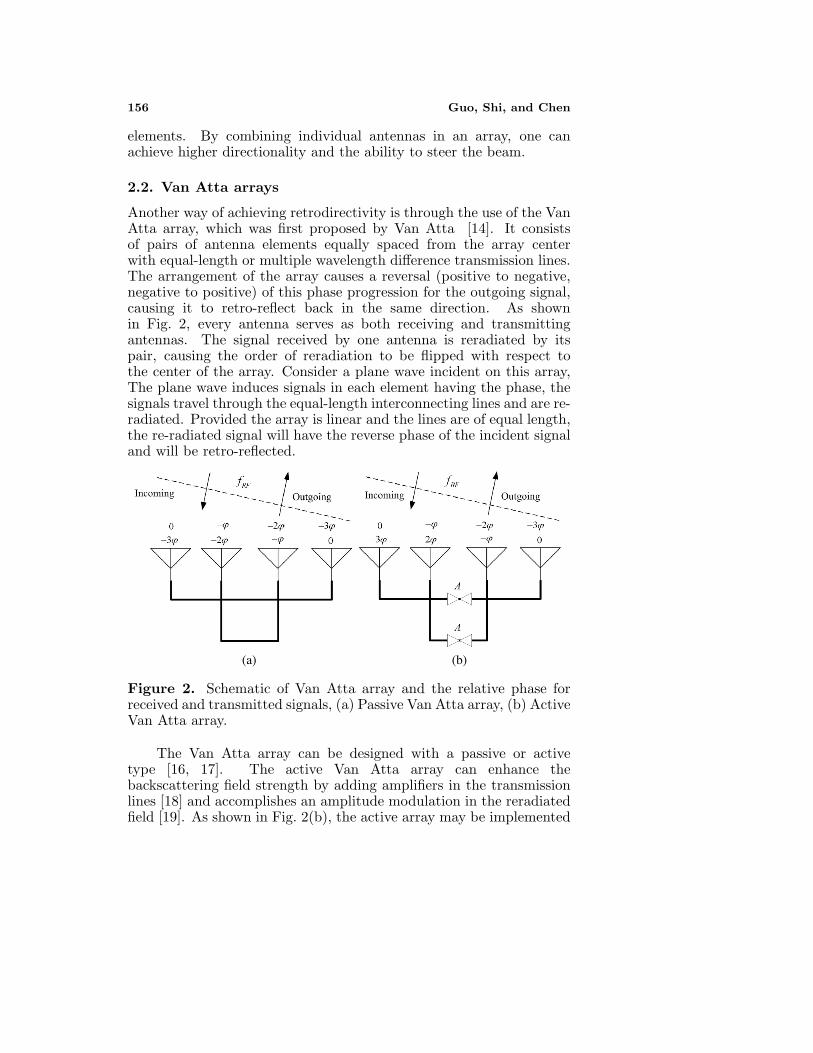
Another way of achieving retrodirectivity is through the use of the VanAtta array, which was first proposed by Van Atta [14]. It consistsof pairs of antenna elements equally spaced from the array centerwith equal-length or multiple wavelength difference transmission lines.The arrangement of the array causes a reversal (positive to negative,negative to positive) of this phase progression for the outgoing signal,causing it to retro-reflect back in the same direction. As shownin Fig. 2, every antenna serves as both receiving and transmittingantennas. The signal received by one antenna is reradiated by itspair, causing the order of reradiation to be flipped with respect tothe center of the array. Consider a plane wave incident on this array,The plane wave induces signals in each element having the phase, thesignals travel through the equal-length interconnecting lines and are re-radiated. Provided the array is linear and the lines are of equal length,the re-radiated signal will have the reverse phase of the incident signaland will be retro-reflected.
(a) (b)
Figure 2. Schematic of Van Atta array and the relative phase forreceived and transmitted signals, (a) Passive Van Atta array, (b) ActiveVan Atta array.
The Van Atta array can be designed with a passive or activetype [16, 17]. The active Van Atta array can enhance thebackscattering field strength by adding amplifiers in the transmissionlines [18] and accomplishes an amplitude modulation in the reradiatedfield [19]. As shown in Fig. 2(b), the active array may be implemented

Progress In Electromagnetics Research B, Vol. 5, 2008 157
by inserting an ordinary unilateral amplifier or a bidirectionalamplifier on the midway of each transmission line. The ratio of thebackscattering field level of the active array over that of a passive oneis exactly equal to the amplifiers’ gain.
The Van Atta array is capable, in principle, of reflecting a waveincident at any angle from end-fire to broadside, but its performance islimited in practice by the directivity of the radiators. Since the lengthsof the connecting transmission lines are equal, the only frequency-dependent component in the Van Atta array is the antenna element.The use of broadband antennas and nondispersive transmission linesallows the array to perform over a wide bandwidth. However, thegeometrical arrangement of the Van Atta array is restricted to planarwavefronts and planar topologies, and makes it spatially inefficient forrealizing retrodirectivity on many applications.
2.3. Phase Conjugation arrays
A more popular technique for realizing retrodirective arrays is basedon phase conjugation using heterodyne techniques [15]. This approachuses the same idea of the reversal of a phase gradient in the Van Attaarray, but phase reversal is achieved at each antenna element insteadof relying on antenna pairs. In this scheme, shown in Fig. 3, eachantenna is connected to a mixer, which in turn is pumped by a localoscillator (LO) with double the frequency of the incident wave. Theheterodyne mixing causes the incoming radiofrequency (RF) signal at
Figure 3. Phase conjugation arrays and the relative phase for receivedand transmitted signals.
158 Guo, Shi, and Chen
each element to mix with a local oscillator (LO), creating the followingmixing product:
VIF = VRF cos (ωRF t + θn)VLO cos (ωLOt)
=12VRF VLO[cos((ωLO − ωRF )t−θn)+cos ((ωLO+ωRF )t+θn)] (1)
If the LO frequency is twice the RF frequency, we obtain thefollowing:
VIF ∝ cos (ωRF t − ϕ) + cos ((3ωRF ) t + ϕ) (2)
Note that the first term in (2), which is the lower sideband product(intermediate frequency, or IF signal), has the same frequency as theincoming RF signal, but with a conjugate phase. An array of suchphase-conjugating elements causes the same kind of phase reversal,resulting in a reradiated beam back toward the source direction, justas in the Van Atta array.
In this method, it is important to eliminate undesired signals sothat only the desired phase-conjugated signal radiates from the array.The second term in (2) is an undesired, non-phase-conjugated signal iseasily filtered and suppressed due to the large difference between thisfrequency (3ωRF ) and the RF (ωRF ). For the same reason, any LOleakage (2ωRF ) can also be easily filtered. Another signal that mustbe suppressed is the RF signal that leaks directly from the input tothe output of the phase conjugator. This signal is exactly the samefrequency as the desired IF signal, but is not phase-conjugated. Itis impossible to filter out the RF leakage signal, as its frequency isthe same as that of the phase-conjugated signal. The RF leakagecreates a mirror beam of the desired retrodirective beam. Therefore,RF leakage suppression is one of the key challenges in the phase-conjugating heterodyne method. In general, balanced mixer topologiesare used to eliminate undesired RF leakage signals. It should be notedthat the phase conjugation is also achieved even if the RF and IFfrequencies are not identical.However, the deviation between the twocarrier frequencies leads to a pointing error in the return beam. Theamount of the error depends on the ∆f (RF-IF) as well as the incomingbeam angle.
Phase conjugation arrays using heterodyne techniques can bedesigned with a passive or active type. Passive phase conjugationarrays using diode mixers generally provide better RF-IF isolationthan do active phase conjugation arrays. The major shortcomingof passive phase conjugation arrays is the conversion loss, whichlimits the distance between the interrogator and the retrodirectivearray. However, the use of active devices such as metal semiconductor

Progress In Electromagnetics Research B, Vol. 5, 2008 159
field-effect transistors (MESFETs) can provide conversion gain duringthe mixing process. It is possible for the active phase conjugationretrodirective array to transpond an amplified signal back to the sourcelocation, without the need for additional amplifiers by using activedevices.
The phase conjugation retrodirective array has the advantage thatthe array elements can be arbitrarily located, not necessarily with equalinterelement spacing, nor in the same plane; thus it easily conforms tothe object surface. Another advantage is that, by changing the LOfrequency, the reradiation wave can be easily frequency-modulated.However, the phase conjugation array needs a mixer circuit witha large-frequency difference between RF and LO signals for eacharray element, and an LO with double the system frequency and acorresponding distribution network from the LO to the entire arrayelements are required. These may make the array complicated, bulky,and costly.
Most of the recently demonstrated retrodirective arrays [1–5] arebased on the heterodyne technique. This method achieves phaseconjugation through hardware, only slightly increasing the circuitcomplexity, while eliminating the need for complex digital signalprocessing. This also allows for the active tracking and self steeringof beam in the direction of a moving target, even without knowingits initial position, and thus is well suited for mobile communicationapplications.
3. CHARACTERIZATION OF RETRODIRECTIVEARRAY
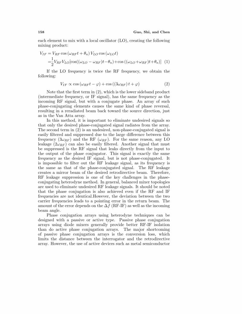
The self-steering performance of a retrodirective antenna array arecharacterized by bistatic and monostatic radar cross sections (RCS),the two standard measurements is illustrated in Fig. 4. Once aninterrogating (incoming) signal impinges on the array under test,the retrodirected signal is transmitted back to the receiving antenna,ideally in the same direction from which it originated.
In the bistatic case, the interrogating antenna remains stationarywhile the receiving antenna scans over a azimuthal range, picks upthis retrodirected signal. The resulting measurement in the patternshows a mainlobe in the direction of the source, with expected nulls orsidelobes occurring as a result of the array directivity. The theoreticalbistatic RCS [5] is given by
σbistatic (θ, θ0, ϕ, ϕ0) =λ2
0
4πGcDe (θ0, ϕ0)De (θ, ϕ) Da (θ, θ0, ϕ, ϕ0) (3)
160 Guo, Shi, and Chen
(a) (b)
Figure 4. Retrodirective array performance is characterized by (a)bistatic RCS and (b) monostatic RCS measurements.
where θ0, ϕ0 are the RF source angles, Gc is the circuit gain, De is thedirectivity of element antenna, and Da is the directivity of the array,given by
Da (θ, θ0, ϕ, ϕ0) =4π |AF (θ, θ0, ϕ, ϕ0)|2∫ 2π
0
∫ π
0
∣∣AF(θ′, θ0, ϕ
′, ϕ0)∣∣2 sin θ′dθ′dϕ′
(4)
where AF (θ, θ0, ϕ, ϕ0) is the array factor.In the bistatic RCS measurement, the radiation pattern of
the retrodirective antenna array is fixed since the position of theinterrogating source (θ0, ϕ0) is fixed. Therefore, the directivity of thearray simply depends on the angle (θ, ϕ), which is the position of thereceiving antenna. Since the array factor is maximum at the angleof the incoming RF signal, the mainlobe of the bistatic RCS patternshould point in the direction of the source.
In the monostatic case, both the interrogating and receivingantennas are collocated and simultaneously scanned. Since theinterrogating and retrodirected signals are both in the same direction,the peak of the array radiation will always be in the direction ofthe receiving antenna, and thus the monostatic pattern will exhibita relatively flat pattern without nulls. The theoretical monostaticRCS [5] is is given by
σmonostatic (θ, ϕ) =λ0
4πGcD
2e (θ, ϕ) Da (θ, ϕ) (5)
Due to the retrodirective nature of the array, the peak of the arrayfactor will always be in the direction of the source. Therefore, themonostatic radar cross-section (RCS) pattern of a retrodirective arrayis simply given using the square of its element directivity multiplied by

Progress In Electromagnetics Research B, Vol. 5, 2008 161
the array directivity in the source direction. Note that the directivityof the array is multiplied only once. This is because the received signalis processed at each element separately without being combined. Thearray factor is involved only when the phase-conjugated signal fromeach element is spatially combined upon transmission.
The monostatic RCS is useful in evaluating the wide anglecoverage of a retrodirective array. The bistatic RCS is useful forevaluating the antiintercept capability (low sidelobe power levels)beam-pointing errors, and scan angle limitations. A typical bistaticand monostatic RCS pattern [1] is shown in Fig. 5.
(a) (b)
Figure 5. Typical RCS pattern of retrodirective antenna array, (a)bistatic RCS, (b) monostatic RCS.
4. ARRAY DESIGN CONSIDERATIONS
4.1. Antenna Element and Array Spacing
In retrodirective antenna array, the antenna element and the arrayspacing design must also include since they are often the limitingfactor in the angular coverage of a retrodirective array. Since theradiation pattern of the array is the product of the antenna elementand array factor, the maximum value of the radiation pattern of thearray does not correspond to the peak of the array factor when anonisotropic element is used. The effect of beam pulling results in abeam-pointing error (BPE), which is defined as the deviation of themainbeam from that of the array factor pattern. Using omnidirectionalantennas or an antenna element with low directivity [20–26], such asa microstrip patch, slot antennas, and printed dipoles, or increasingthe number of elements reduces this error [27]. Using a low-directivity
162 Guo, Shi, and Chen
element also decreases the dependence of the retrodirected power onthe interrogation angle.
Another design concern is the array spacing. The array spacingshould satisfy the condition given by (6) in order to avoid scan anglelimitations due to grating lobes:
d <λ0
(1 + |sin θin|)(6)
where d is the array spacing, λ0 is the free-space wavelength of theinterrogating RF signal, and θin is the incident angle of the incomingsignal. For scanning from −90 deg to 90 deg without grating lobes, thearray spacing must be less than a half-wavelength of the RF signal. Thesmall array spacing allows the array to avoid scan angle limitations dueto grating lobes, which become visible when the array spacing is toolarge.
4.2. Receive and Transmit Isolation
Since the interrogating and retrodirected signals share the samefrequency, there is always unavoidable coupling between theinterrogating and receiving antennas. Various methods, such asminimal frequency offsets, or orthogonal polarizations [28], can be usedto ensure that the received and transmitted signals do not influenceeach other and effect the phase conjugation. A popular techniquefor separating the received and transmitted signals is used by slightlyoffsetting the frequencies so that the two signals can be resolvedon a spectrum analyzer. Phase conjugation is achieved even if theinterrogating and retrodirected frequencies are not identical, but thedeviation between these two frequencies leads to a pointing error in thereturn beam [27]. The amount of the error depends on this frequencydifference as well as the incoming beam angle. The shift of the mainbeam due to a frequency change in the array is given by:
sin θin
sin θs=
fin − f∆
fin(7)
where θin, θs is the incoming angle and the scattering anglerespectively, f∆ = fout − fin, fin, fout is the frequency of the incomingsignal and outgoing signal respectively.
When frequency offsets is introduced into the retransmitted signalin retrodirective system, here appropriate choice of the retransmissionfrequency can be used to partially compensate for the effect of beampulling by the directivity of the antenna elements. The choice lowerretransmitted frequency as compared to the frequency of the receivedsignal generates best retrodirective response [27].

Progress In Electromagnetics Research B, Vol. 5, 2008 163
4.3. Modulation and Phase Conjugation Circuits
Passive retrodirective arrays only reradiate the incoming signalswithout modifying the signals. This system cannot be used to transmitinformation and it is only a transponder. Heterodyne retrodirectivearrays using an LO at twice the frequency of the incoming signalalso re-transmit the original signal, additional information canbe re-transmitted by modulating the LO or IF and makes thisimplementation useful for wireless communication. To receive andtransmit information independently of the array geometry, the receivermust recover separately the incident carrier phase and the modulationused to encode the desired information. A retrodirective system basedheterodyne technique using an IF can achieve this using a carrierrecovery circuit. Carrier recovery circuits are therefore often usedin these system and can be adapted to be used in a retrodirectiveimplementation. It should be noted that the ability of the systemto modulate the RF signal determines the complexity of the phaseconjugation circuits.
Retrodirective array system consist of many channels, retrodirec-tivity of the array is achieved by re-transmitting the signal with thephase conjugation of the incoming signal, each channel must thereforehave an identical phase shift and any difference in phase shift fromchannel to channel will affect the radiation pattern of the array. Asthe array increases in size, phase balance becomes more critical. Whendesigning the array one must determine an acceptable phase differencebetween channels and design each channel taking into considerationappropriate tolerances.
5. FURTHER RESEARCH
In any wireless communication system, interfering sources can playa detrimental role to system performance. In recent years, thefunctionality and application of retrodirective arrays have advancedfrom originally simple. self-steering receiving antennas or trackingdevices to more complex integrated systems, with the inclusion ofmodulation schemes, multiple frequency operation, reconfigurability,and even full-duplex capability [29]. However, in all cases, the mainlimitation is its inability to operate effectively under interference, or inscenarios with multiple interrogators, so retrodirective arrays remainvulnerable to interference. The retrodirective array capable of adaptiveinterference rejection will be the further research area [30, 31].
As a result of the fact, retrodirective array technology playsimportant roles in wireless communication systems. One of thelimitations of many retrodirective arrays prototypes is the power

164 Guo, Shi, and Chen
dependence of the retrodirected signal on the interrogating signal.Since the signal must travel a distance R to the retrodirectivearray and back, the power level of the signal will be proportionalto approximately 1/R4, significantly reducing the efficiency of thesystem. This is especially important in the case that available power isseverally limited. To obtain a strong and constant retrodirected powerlevel transmitted back to the source, the methods of decoupling theretrodirective signal from the interrogating signal must be used and dofurther research [3].
In a multipath environment, there are multiple paths ofsignal propagation that can lead to fading and interference in thecommunication path. In the theory, retrodirectivity completelyeliminates the fading effects of multipath propagation in the roundtripcommunication link. However, the mainbeam rays of retrodirectivearray add coherently while the sidelobe rays add incoherently, thuslimiting the method in practical systems [32]. The ability of theretrodirective transceiver to reduce multipath effects and fadingrequires further research [33]. The response to real-world, dynamicconditions of the retrodirective array should be investigated.
Recent research on retrodirective systems has also generallyfocused on the performance of a single retrodirective transceiver [4].Further research is required to establish performance of a full radio linkconsisting of two retrodirective transceivers, and the most economicmethod of integrating a retrodirective system should be investigatedto reduce the cost and hardware requirements of antenna arrays [34].
6. CONCLUSIONS
Retrodirective arrays have the unique ability to retransmit signalsback to its origination point without a priori knowledge. Thisis accomplished without complexity of digital signal processor andrely on purely analog circuitry offers system simplicity and high-speed response. This paper summarizes the methods of achievingretrodirectivity from the initial use of passive methods to theintegration of active devices to increase returned signal power,introduces the self-steering performance characterized by bistatic andmonostatic radar cross sections of a retrodirective antenna array.A series of array design considerations in the retrodirective arraysystems is presented and can play a key role to system performance.Further researches in this area are presented and will bring about newtechnologies and applications.

Progress In Electromagnetics Research B, Vol. 5, 2008 165
REFERENCES
1. Leong, K. M. K. H., R. Y. Miyamoto, and T. Itoh, “Movingforward in retrodirective antenna arrays,” IEEE Potentials,Vol. 22, No. 3, 16–21, 2003.
2. Shiroma, W. A., R. Y. Miyamoto, G. S. Shiroma, et al., “Progressin retrodirective arrays for wireless communications,” IEEETopical Conference on Wireless Communication Technology, 80–81, 2003.
3. Roque, J. D., B. T. Murakami, S. S. Sung, et al., “Progress inself-steering antennas for small-satellite networks,” Space 2004Conference and Exhibit, 1–7, 2004.
4. Goshi, D. S., K. M. K. H. Leong, and T. Itoh, “Recent advancesin retrodirective system technology,” IEEE Radio and WirelessSymp., 459–462, 2006.
5. Miyamoto, R. Y. and T. Itoh, “Retrodirective arrays for wirelesscommunications,” IEEE Microwave Mag., Vol. 3, No. 1, 71–79,2002.
6. Miyamoto, R. Y., G. S. Shiroma, B. T. Murakami, et al., “A high-directivity transponder using self-steering arrays,” IEEE MTT-SInt. Microwave Symp. Digest, Vol. 3, 1683–1686, 2004.
7. Gupta, S. and E. R. Brown, “Noise-correlating radar based onretrodirective antennas,” IEEE Transactions on Aerospace andElectronic Systems, Vol. 43, No. 2, 472–477, 2007.
8. Chiu, L., T. Y. Yum, W. S. Chang, et al., “Retrodirective array forRFID and microwave tracking beacon applications,” MicrowaveOpt. Tech. Lett., Vol. 48, No. 2, 409–411, 2006.
9. Yu-Jiun, R. and C. Kai, “New 5.8-GHz circularly polarizedretrodirective rectenna arrays for wireless power transmission,”IEEE Trans. on Microwave Theory Tech., Vol. 54, No. 7, 2970–2976, 2006.
10. Lim, S., K. M. K. H. Leong, and T. Itoh, “Adaptive powercontrollable retrodirective array system for wireless sensor serverapplications,” IEEE Trans. Microwave Theory Tech., Vol. 53,No. 12, 3735–3743, 2005.
11. Leong, K. M. K. H. and T. Itoh, “Mutually exclusive dataencoding for realization of a full duplexing self-steering wirelesslink using a retrodirective array transceiver,” IEEE Trans.Microwave Theory Tech., Vol. 53, No. 12, 3687–3696, 2005.
12. Leong, K. M. K. H. and T. Itoh, “Full-duplex retrodirectivearray using mutually-exclusive uplink and downlink modulationschemes,” IEEE MTT-S Int. Microwave Symp. Digest, Vol. 3,

166 Guo, Shi, and Chen
1695–1698, 2004.13. Sharp, E. D. and M. A. Diab, “Van Atta reflector array,” IRE
Trans. on Anten. Propag., Vol. 8, No. 4, 436–438, 1960.14. Atta, L. C. V., “Electromagnetic reflector,” U.S. Patent,
Vol. 2908, 1959.15. Pon, C. Y., “Retrodirective array using the heterodyne
technique,” IEEE Trans. Anten. Propag., Vol. 12, No. 2, 176–180,1964.
16. Chung, S. J., S.-M. Chen, and Y.-C. Lee, “A novel bi-directionalamplifier with applications in active Van Atta retrodirectivearrays,” IEEE Trans. Microwave Theory Tech., Vol. 51, No. 2I,542–547, 2003.
17. Withers, M. J., “An active Van Atta array,” Proceedings of theInstitution of Electrical Engineers, Vol. 111, No. 5, 982–984, 1964.
18. Hansen, R. C., “Communications satellites using arrays,” Proc. ofIRE, Vol. 49, No. 6, 1066–1074, 1961.
19. Bauer, L. H., “Technique for amplitude modulating a Van Attaradar reflector,” Proc. of IRE, Vol. 49, 634–635, 1961.
20. Chen, K., X. Chen, and K. Huang, “A novel microstrip dipoleantenna with wideband and end-fire properties,” Journal ofElectromagnetic Waves and Applications, Vol. 21, No. 12, 1679–1688, 2007.
21. Cui, B., J. Zhang, and X. W. Sun, “Single layer microstrip antennaarrays applied in millimeter-wave radar front-end,” Journal ofElectromagnetic Waves and Applications, Vol. 22, No. 1, 3–15,2008.
22. Zhang, M. T., Y. B. Chen, Y. C. Jiao, et al., “Dual circularlypolarized antenna of compact structure for RFID application,”Journal of Electromagnetic Waves and Applications, Vol. 20,No. 14, 1895–1902, 2006.
23. Wu, G. L., W. Mu, G. Zhao, et al., “A novel design ofdual circularly polarized antenna FED by L-strip,” Progress InElectromagnetics Research, PIER 79, 39–46, 2008.
24. Yang, S. L. S., K. F. Lee, and A. A. Kishk, “Design and studyof wideband single feed circularly polarized microstrip antennas,”Progress In Electromagnetics Research, PIER 80, 45–61, 2008.
25. Abbaspour, M. and H. R. Hassani, “Wideband star-shapedmicrostrip patch antenna,” Progress In Electromagnetics ResearchLetters, Vol. 1, 61–68, 2008.

Progress In Electromagnetics Research B, Vol. 5, 2008 167
26. Ansari, J. A. and R. B. Ram, “Tunnel diode integrated E-shaped patch antenna for broadband operation,” Progress InElectromagnetics Research Letters, Vol. 1, 263–273, 2008.
27. Toh, B. Y., V. F. Fusco, and N. B. Buchanan, “Assessmentof performance limitations of PON retrodirective arrays,” IEEETrans. Anten. Propag., Vol. 50, No. 10, 1425–1432, 2002.
28. Luxey, C. and J. M. Laheurte, “A retrodirective transponderwith polarization duplexing for dedicated short-range communi-cations,” IEEE Trans. Microwave Theory Tech., Vol. 47, No. 9,1910–1915, 1999.
29. Shiroma, G. S., R. Y. Miyamoto, and W. A. Shiroma, “A full-duplex dual-frequency self-steering array using phase detectionand phase shifting,” IEEE Trans. Microwave Theory Tech.,Vol. 54, No. 1, 128–133, 2006.
30. Goshi, D., K. Leong, and T. Itoh, “A retrodirective array withinterference rejection capability,” IEEE MTT-S Int. MicrowaveSymp. Digest, Vol. 1, 395–398, 2005.
31. Goshi, D. S., K. M. K. H. Leong, and T. Itoh, “Interleavedretrodirective sub-arrays for null-steering interference rejection,”IEEE MTT-S Int. Microwave Symp. Digest, 1719–1722, 2007.
32. Tuovinen, J., G. S. Shiroma, W. E. Forsyth, et al., “Multipathcommunications using a phase-conjugate array,” IEEE MTT-SInt. Microwave Symp. Digest, Vol. 3,1681–1684, 2003.
33. Loadman, C. and C. Zhizhang, “A study of retrodirectivearray performance in the presence of multipath,” Second AnnualConference on Communication Networks and Services Research,56–60, 2004.
34. Goshi, D. S., K. M. K. H. Leong, and T. Itoh, “A sparseretrodirective transponder array with a time shared phase-conjugator,” IEEE Trans. Anten. Propag., Vol. 55, No. 8, 2367–2372, 2007.