retinette 1a shutter repair - retinarescue.com · slot. this is the spring-loaded detent that...
TRANSCRIPT
1
Kodak Retinette 1A shutter strip-down by Chris Sherlock
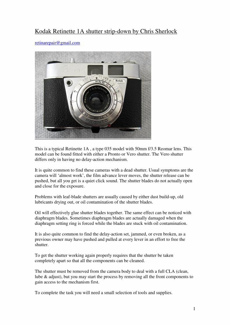
This is a typical Retinette 1A , a type 035 model with 50mm f/3.5 Reomar lens. This
model can be found fitted with either a Pronto or Vero shutter. The Vero shutter
differs only in having no delay-action mechanism.
It is quite common to find these cameras with a dead shutter. Usual symptoms are the
camera will ‘almost work’, the film advance lever moves, the shutter release can be
pushed, but all you get is a quiet click sound. The shutter blades do not actually open
and close for the exposure.
Problems with leaf-blade shutters are usually caused by either dust build-up, old
lubricants drying out, or oil contamination of the shutter blades.
Oil will effectively glue shutter blades together. The same effect can be noticed with
diaphragm blades. Sometimes diaphragm blades are actually damaged when the
diaphragm setting ring is forced while the blades are stuck with oil contamination.
It is also quite common to find the delay-action set, jammed, or even broken, as a
previous owner may have pushed and pulled at every lever in an effort to free the
shutter.
To get the shutter working again properly requires that the shutter be taken
completely apart so that all the components can be cleaned.
The shutter must be removed from the camera body to deal with a full CLA (clean,
lube & adjust), but you may start the process by removing all the front components to
gain access to the mechanism first.
To complete the task you will need a small selection of tools and supplies.
2
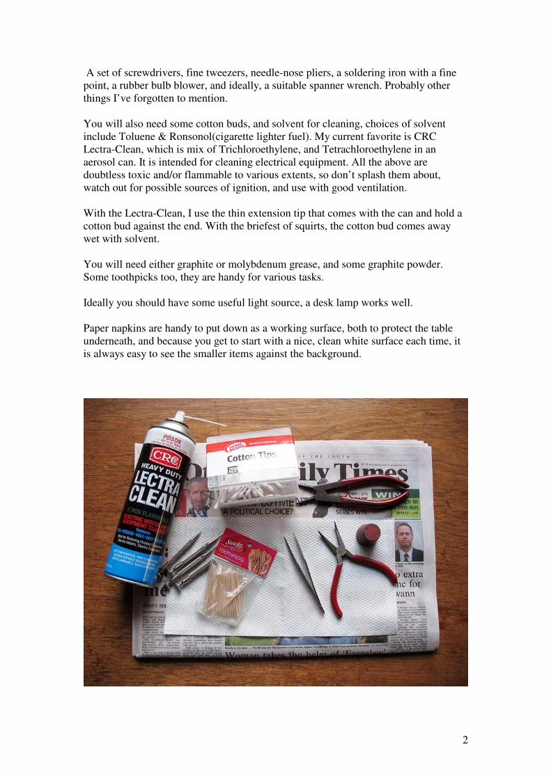
A set of screwdrivers, fine tweezers, needle-nose pliers, a soldering iron with a fine
point, a rubber bulb blower, and ideally, a suitable spanner wrench. Probably other
things I’ve forgotten to mention.
You will also need some cotton buds, and solvent for cleaning, choices of solvent
include Toluene & Ronsonol(cigarette lighter fuel). My current favorite is CRC
Lectra-Clean, which is mix of Trichloroethylene, and Tetrachloroethylene in an
aerosol can. It is intended for cleaning electrical equipment. All the above are
doubtless toxic and/or flammable to various extents, so don’t splash them about,
watch out for possible sources of ignition, and use with good ventilation.
With the Lectra-Clean, I use the thin extension tip that comes with the can and hold a
cotton bud against the end. With the briefest of squirts, the cotton bud comes away
wet with solvent.
You will need either graphite or molybdenum grease, and some graphite powder.
Some toothpicks too, they are handy for various tasks.
Ideally you should have some useful light source, a desk lamp works well.
Paper napkins are handy to put down as a working surface, both to protect the table
underneath, and because you get to start with a nice, clean white surface each time, it
is always easy to see the smaller items against the background.
3
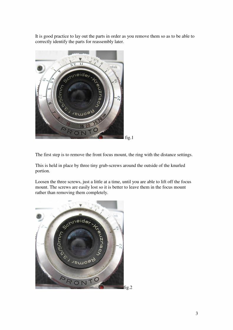
It is good practice to lay out the parts in order as you remove them so as to be able to
correctly identify the parts for reassembly later.
fig.1
The first step is to remove the front focus mount, the ring with the distance settings.
This is held in place by three tiny grub-screws around the outside of the knurled
portion.
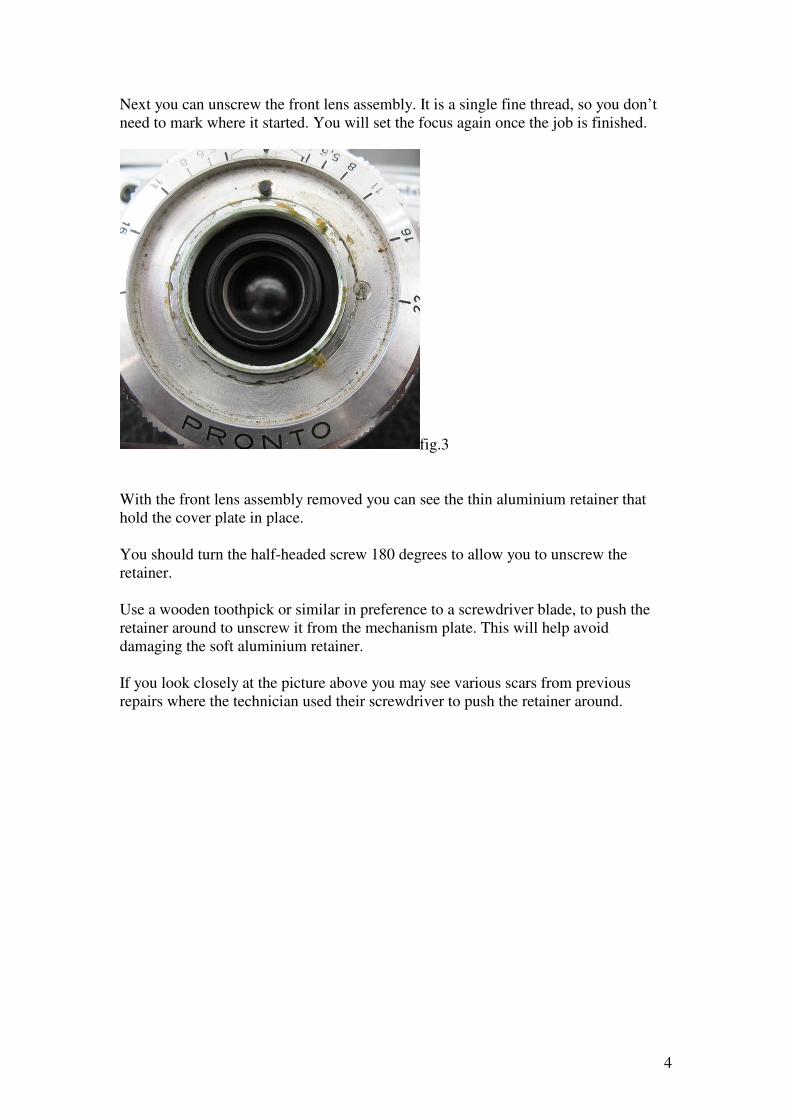
Loosen the three screws, just a little at a time, until you are able to lift off the focus
mount. The screws are easily lost so it is better to leave them in the focus mount
rather than removing them completely.
fig.2
4
Next you can unscrew the front lens assembly. It is a single fine thread, so you don’t
need to mark where it started. You will set the focus again once the job is finished.
fig.3
With the front lens assembly removed you can see the thin aluminium retainer that
hold the cover plate in place.
You should turn the half-headed screw 180 degrees to allow you to unscrew the
retainer.
Use a wooden toothpick or similar in preference to a screwdriver blade, to push the
retainer around to unscrew it from the mechanism plate. This will help avoid
damaging the soft aluminium retainer.
If you look closely at the picture above you may see various scars from previous
repairs where the technician used their screwdriver to push the retainer around.
5
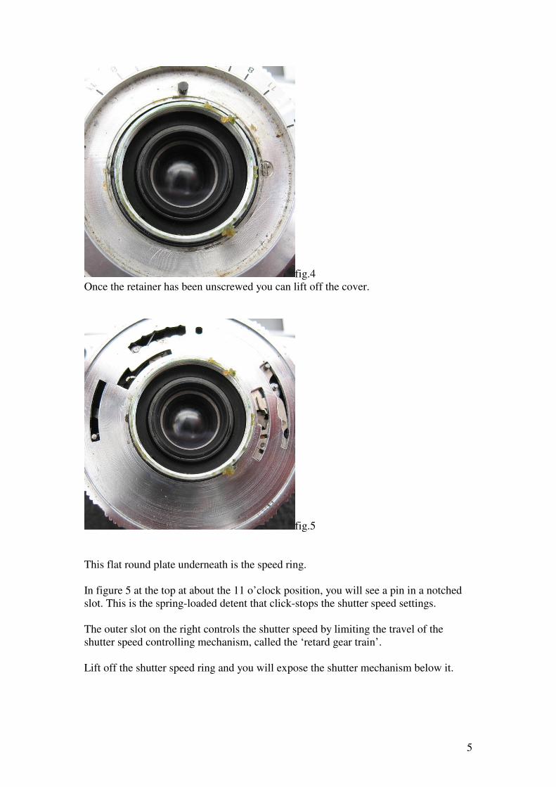
fig.4
Once the retainer has been unscrewed you can lift off the cover.
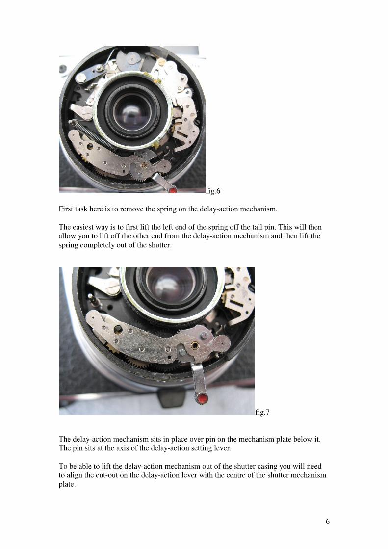
fig.5
This flat round plate underneath is the speed ring.
In figure 5 at the top at about the 11 o’clock position, you will see a pin in a notched
slot. This is the spring-loaded detent that click-stops the shutter speed settings.
The outer slot on the right controls the shutter speed by limiting the travel of the
shutter speed controlling mechanism, called the ‘retard gear train’.
Lift off the shutter speed ring and you will expose the shutter mechanism below it.
6
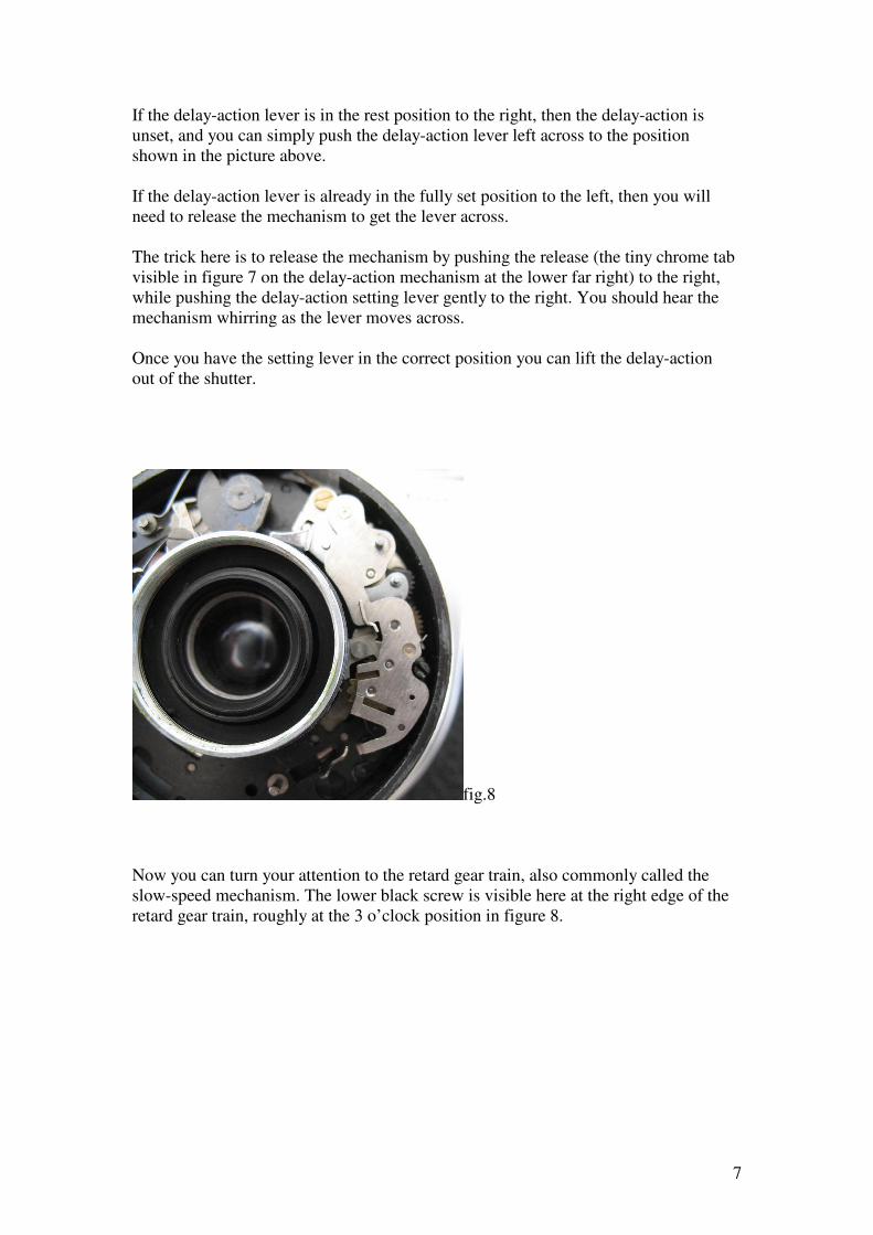
fig.6
First task here is to remove the spring on the delay-action mechanism.
The easiest way is to first lift the left end of the spring off the tall pin. This will then
allow you to lift off the other end from the delay-action mechanism and then lift the
spring completely out of the shutter.
fig.7
The delay-action mechanism sits in place over pin on the mechanism plate below it.
The pin sits at the axis of the delay-action setting lever.
To be able to lift the delay-action mechanism out of the shutter casing you will need
to align the cut-out on the delay-action lever with the centre of the shutter mechanism
plate.
7
If the delay-action lever is in the rest position to the right, then the delay-action is
unset, and you can simply push the delay-action lever left across to the position
shown in the picture above.
If the delay-action lever is already in the fully set position to the left, then you will
need to release the mechanism to get the lever across.
The trick here is to release the mechanism by pushing the release (the tiny chrome tab
visible in figure 7 on the delay-action mechanism at the lower far right) to the right,
while pushing the delay-action setting lever gently to the right. You should hear the
mechanism whirring as the lever moves across.
Once you have the setting lever in the correct position you can lift the delay-action
out of the shutter.
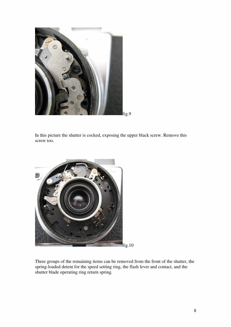
fig.8
Now you can turn your attention to the retard gear train, also commonly called the
slow-speed mechanism. The lower black screw is visible here at the right edge of the
retard gear train, roughly at the 3 o’clock position in figure 8.
8
fig.9
In this picture the shutter is cocked, exposing the upper black screw. Remove this
screw too.
fig.10
Three groups of the remaining items can be removed from the front of the shutter, the
spring-loaded detent for the speed setting ring, the flash lever and contact, and the
shutter blade operating ring return spring.
9
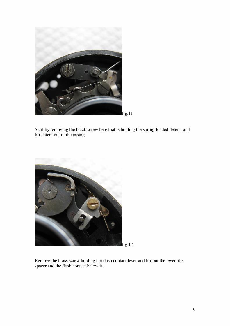
fig.11
Start by removing the black screw here that is holding the spring-loaded detent, and
lift detent out of the casing.
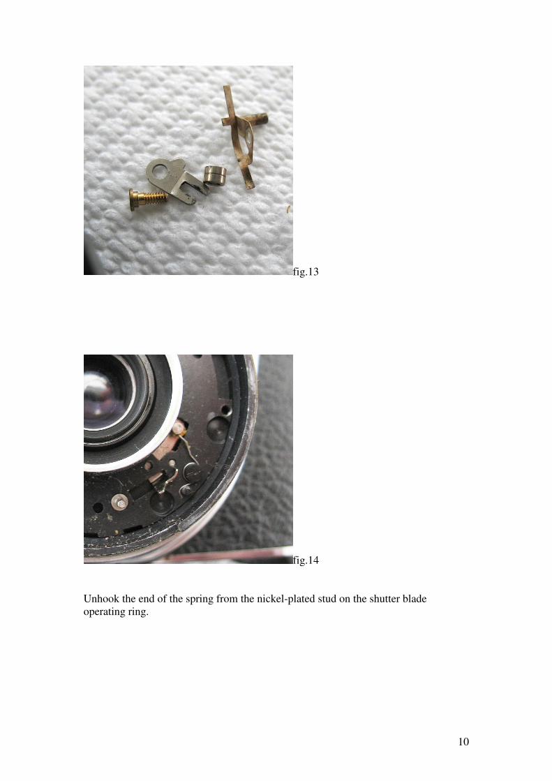
fig.12
Remove the brass screw holding the flash contact lever and lift out the lever, the
spacer and the flash contact below it.
10
fig.13
fig.14
Unhook the end of the spring from the nickel-plated stud on the shutter blade
operating ring.
11
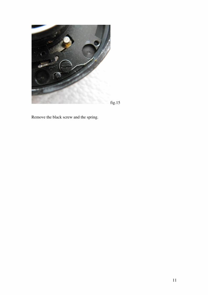
fig.15
Remove the black screw and the spring.
12
Now we are ready to remove the shutter housing from the camera body.
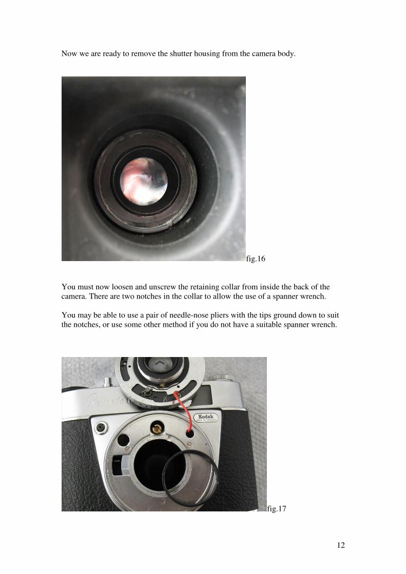
fig.16
You must now loosen and unscrew the retaining collar from inside the back of the
camera. There are two notches in the collar to allow the use of a spanner wrench.
You may be able to use a pair of needle-nose pliers with the tips ground down to suit
the notches, or use some other method if you do not have a suitable spanner wrench.
fig.17
13
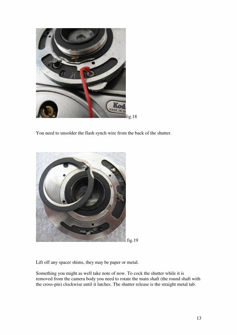
fig.18
You need to unsolder the flash synch wire from the back of the shutter.
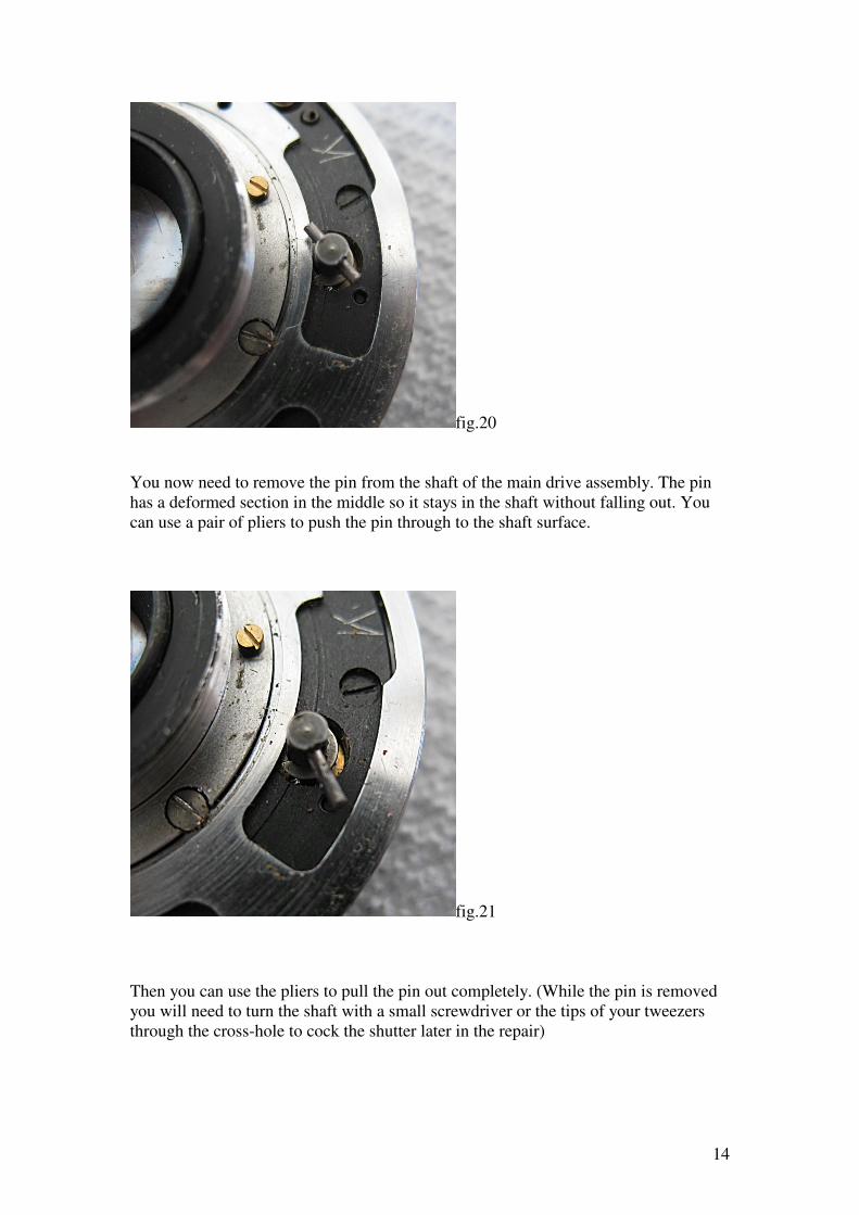
fig.19
Lift off any spacer shims, they may be paper or metal.
Something you might as well take note of now. To cock the shutter while it is
removed from the camera body you need to rotate the main shaft (the round shaft with
the cross-pin) clockwise until it latches. The shutter release is the straight metal tab.
14
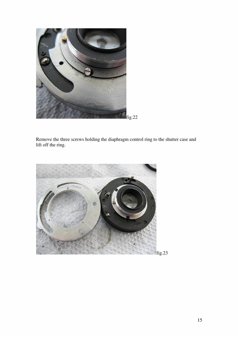
fig.20
You now need to remove the pin from the shaft of the main drive assembly. The pin
has a deformed section in the middle so it stays in the shaft without falling out. You
can use a pair of pliers to push the pin through to the shaft surface.
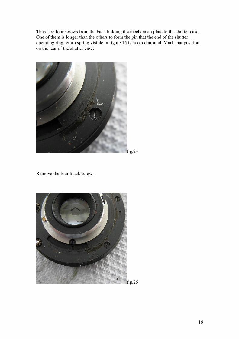
fig.21
Then you can use the pliers to pull the pin out completely. (While the pin is removed
you will need to turn the shaft with a small screwdriver or the tips of your tweezers
through the cross-hole to cock the shutter later in the repair)
15
fig.22
Remove the three screws holding the diaphragm control ring to the shutter case and
lift off the ring.
fig.23
16
There are four screws from the back holding the mechanism plate to the shutter case.
One of them is longer than the others to form the pin that the end of the shutter
operating ring return spring visible in figure 15 is hooked around. Mark that position
on the rear of the shutter case.
fig.24
Remove the four black screws.
fig.25
17
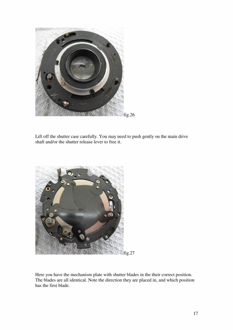
fig.26
Lift off the shutter case carefully. You may need to push gently on the main drive
shaft and/or the shutter release lever to free it.
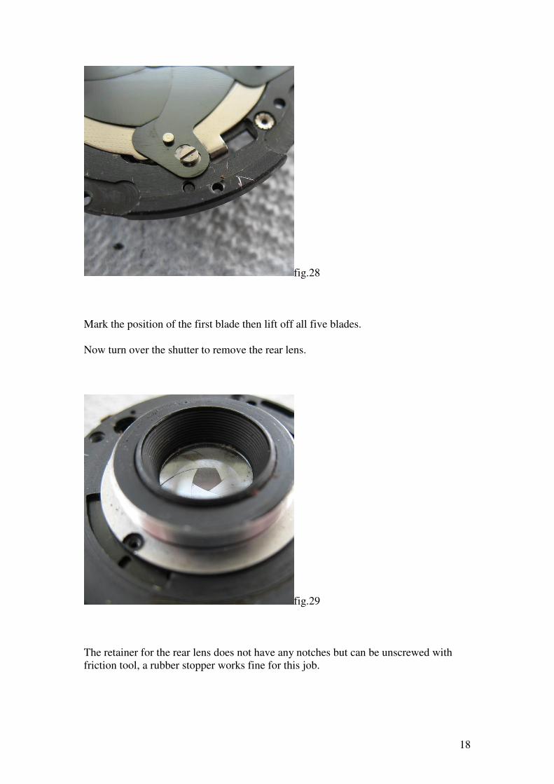
fig.27
Here you have the mechanism plate with shutter blades in the their correct position.
The blades are all identical. Note the direction they are placed in, and which position
has the first blade.
18
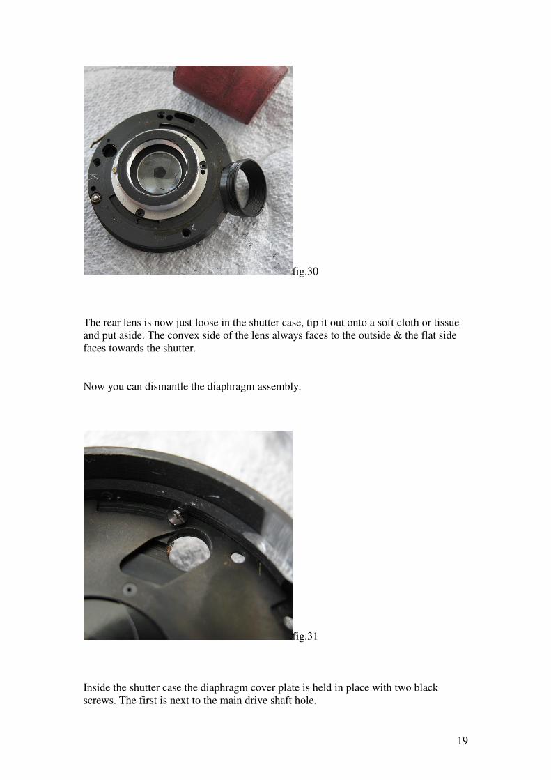
fig.28
Mark the position of the first blade then lift off all five blades.
Now turn over the shutter to remove the rear lens.
fig.29
The retainer for the rear lens does not have any notches but can be unscrewed with
friction tool, a rubber stopper works fine for this job.
19
fig.30
The rear lens is now just loose in the shutter case, tip it out onto a soft cloth or tissue
and put aside. The convex side of the lens always faces to the outside & the flat side
faces towards the shutter.
Now you can dismantle the diaphragm assembly.
fig.31
Inside the shutter case the diaphragm cover plate is held in place with two black
screws. The first is next to the main drive shaft hole.
20
The second screw is directly opposite.
fig.32
Lift off the diaphragm cover plate.
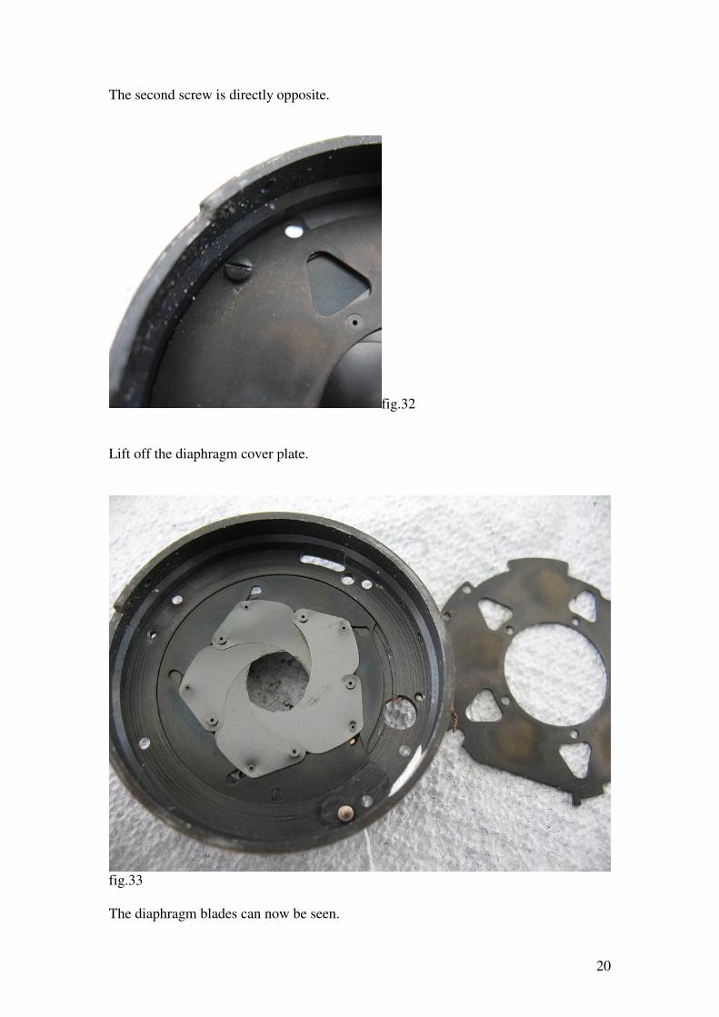
fig.33
The diaphragm blades can now be seen.
21
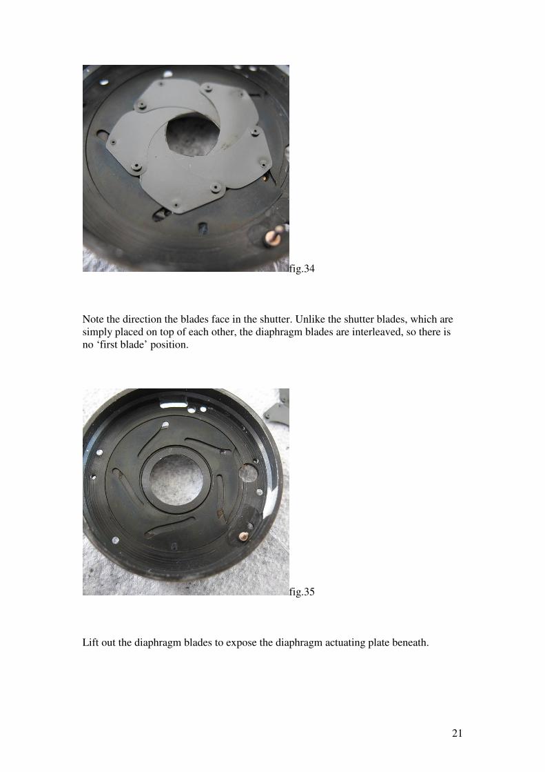
fig.34
Note the direction the blades face in the shutter. Unlike the shutter blades, which are
simply placed on top of each other, the diaphragm blades are interleaved, so there is
no ‘first blade’ position.
fig.35
Lift out the diaphragm blades to expose the diaphragm actuating plate beneath.
22
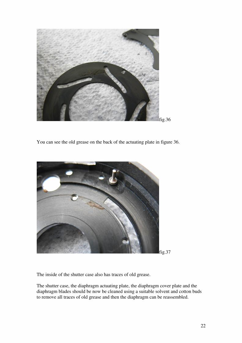
fig.36
You can see the old grease on the back of the actuating plate in figure 36.
fig.37
The inside of the shutter case also has traces of old grease.
The shutter case, the diaphragm actuating plate, the diaphragm cover plate and the
diaphragm blades should be now be cleaned using a suitable solvent and cotton buds
to remove all traces of old grease and then the diaphragm can be reassembled.
23
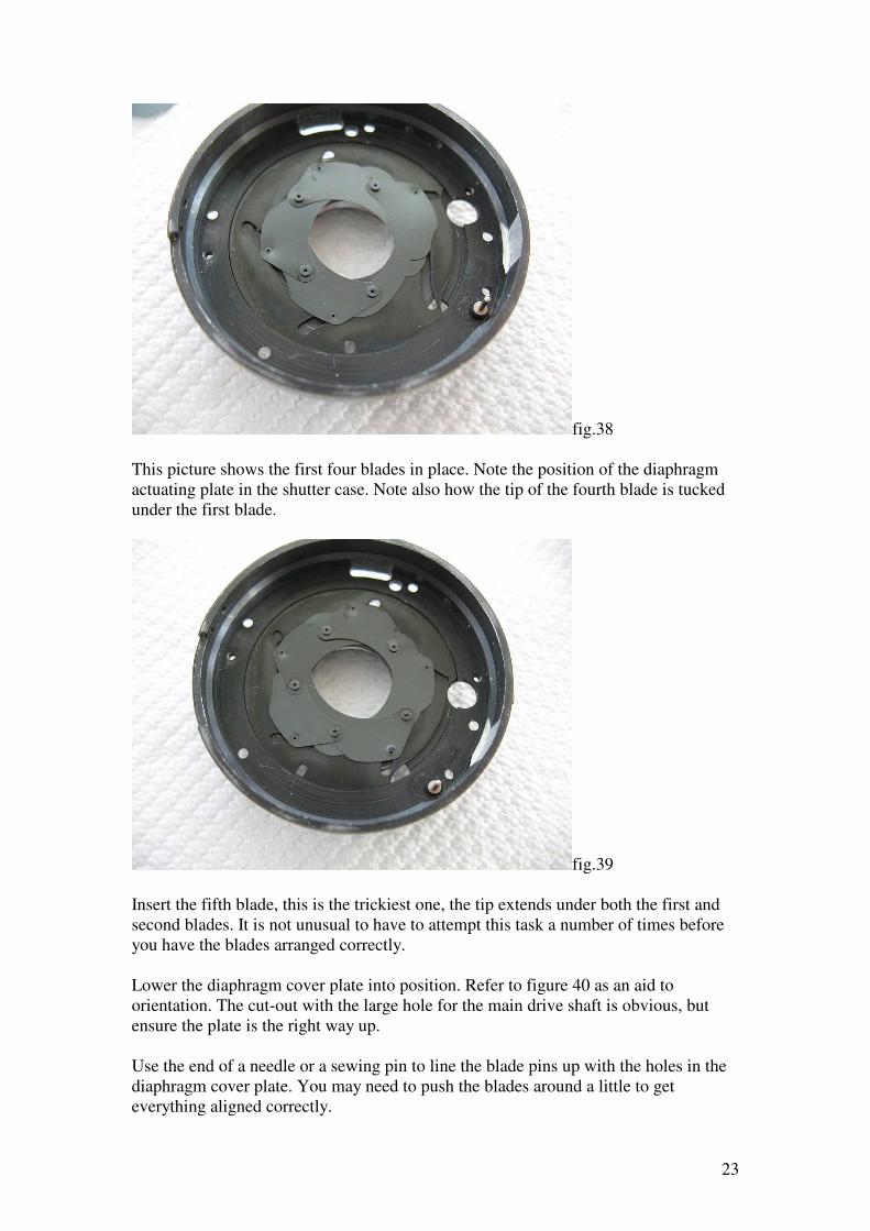
fig.38
This picture shows the first four blades in place. Note the position of the diaphragm
actuating plate in the shutter case. Note also how the tip of the fourth blade is tucked
under the first blade.
fig.39
Insert the fifth blade, this is the trickiest one, the tip extends under both the first and
second blades. It is not unusual to have to attempt this task a number of times before
you have the blades arranged correctly.
Lower the diaphragm cover plate into position. Refer to figure 40 as an aid to
orientation. The cut-out with the large hole for the main drive shaft is obvious, but
ensure the plate is the right way up.
Use the end of a needle or a sewing pin to line the blade pins up with the holes in the
diaphragm cover plate. You may need to push the blades around a little to get
everything aligned correctly.
24
Once you have one or more of the blades seated start the screws that hold the cover
plate to the shutter casing. Tighten the screws only when all blades are seated
properly.
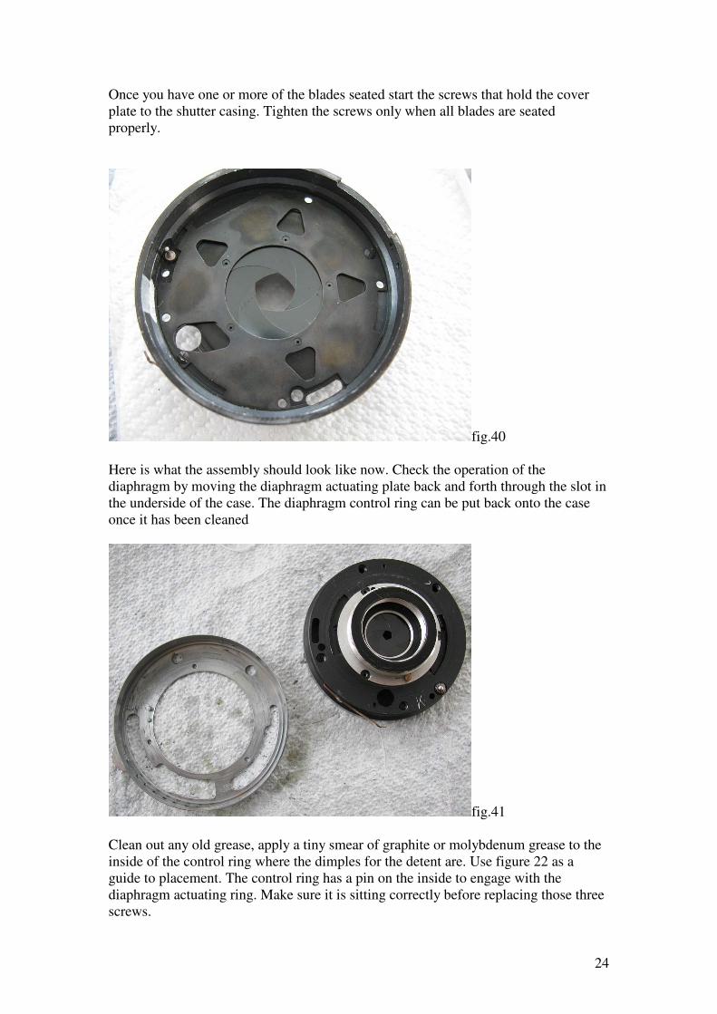
fig.40
Here is what the assembly should look like now. Check the operation of the
diaphragm by moving the diaphragm actuating plate back and forth through the slot in
the underside of the case. The diaphragm control ring can be put back onto the case
once it has been cleaned
fig.41
Clean out any old grease, apply a tiny smear of graphite or molybdenum grease to the
inside of the control ring where the dimples for the detent are. Use figure 22 as a
guide to placement. The control ring has a pin on the inside to engage with the
diaphragm actuating ring. Make sure it is sitting correctly before replacing those three
screws.
25
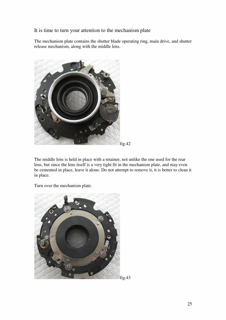
It is time to turn your attention to the mechanism plate
The mechanism plate contains the shutter blade operating ring, main drive, and shutter
release mechanism, along with the middle lens.
fig.42
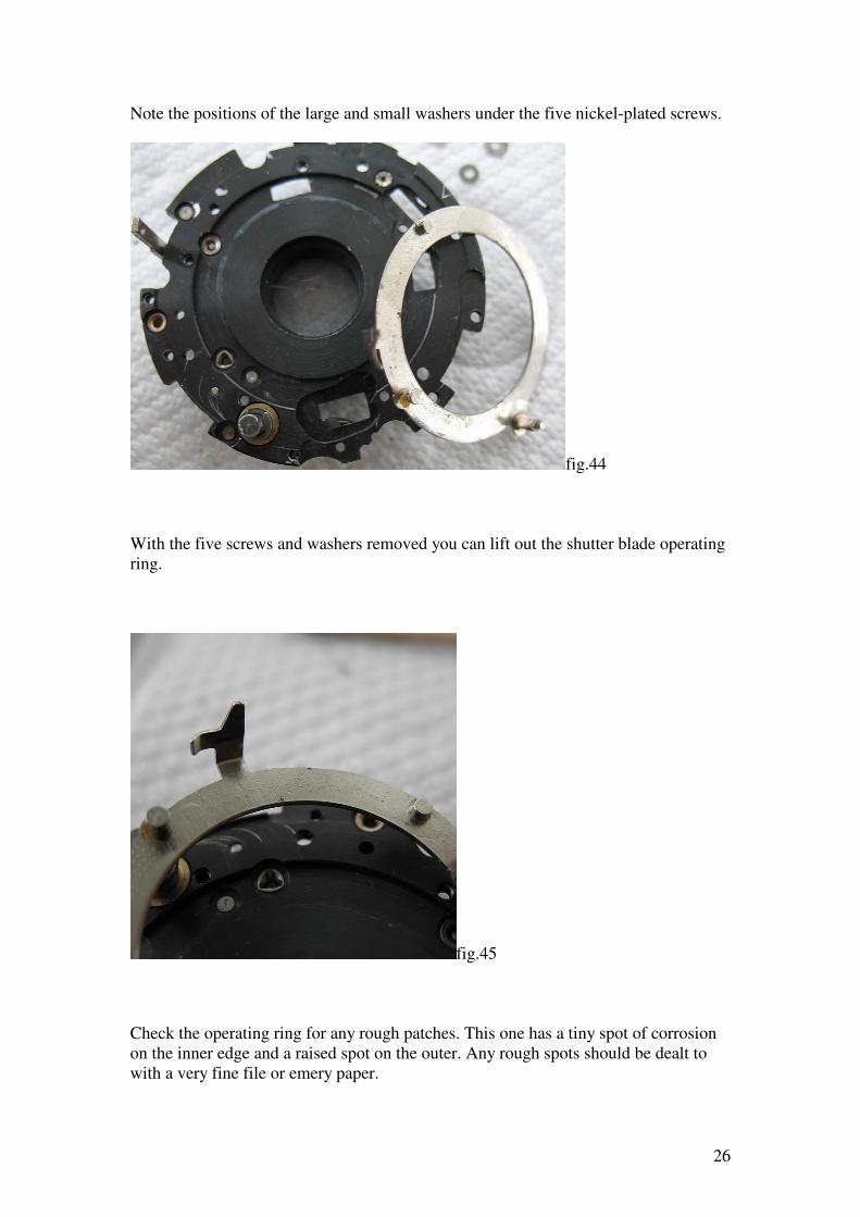
The middle lens is held in place with a retainer, not unlike the one used for the rear
lens, but since the lens itself is a very tight fit in the mechanism plate, and may even
be cemented in place, leave it alone. Do not attempt to remove it, it is better to clean it
in place.
Turn over the mechanism plate.
fig.43
26
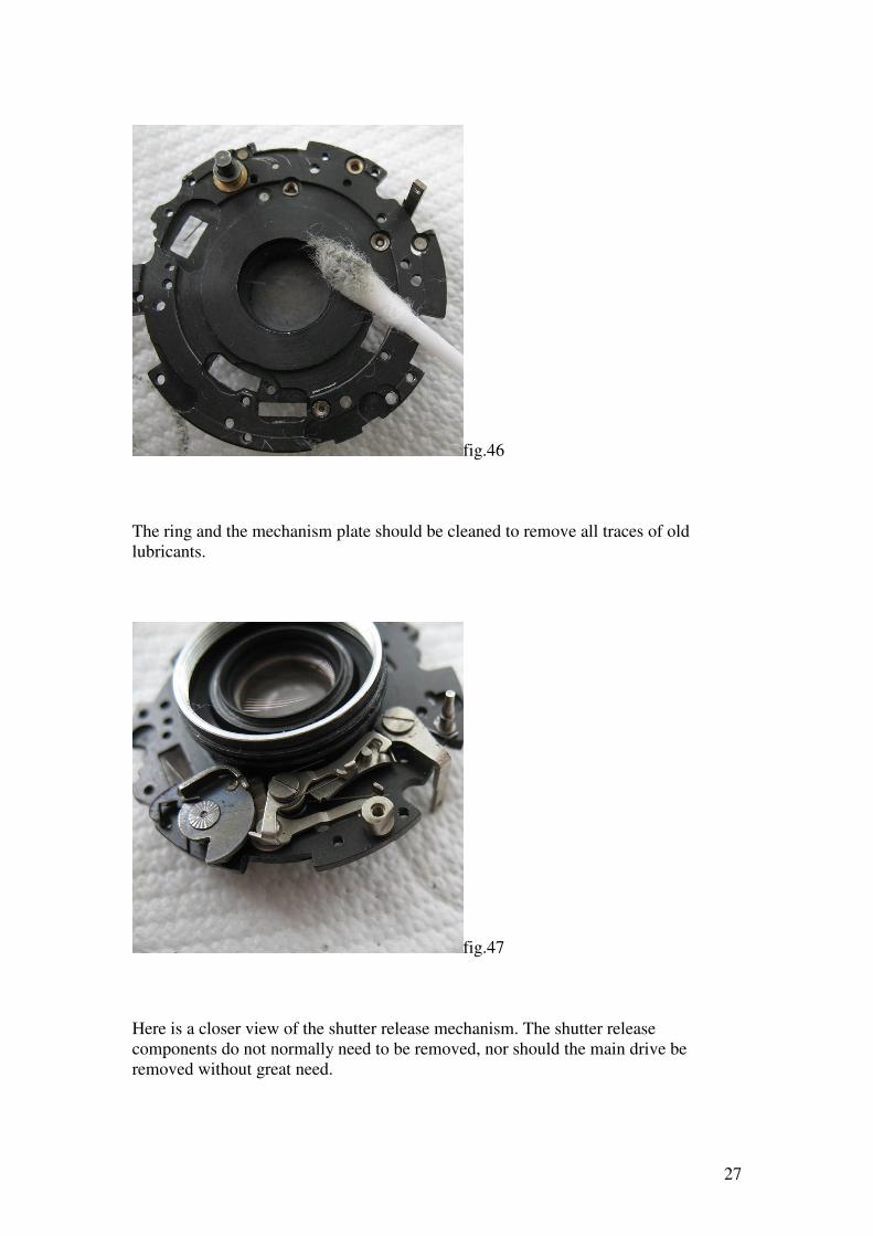
Note the positions of the large and small washers under the five nickel-plated screws.
fig.44
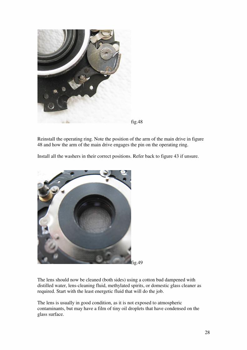
With the five screws and washers removed you can lift out the shutter blade operating
ring.
fig.45
Check the operating ring for any rough patches. This one has a tiny spot of corrosion
on the inner edge and a raised spot on the outer. Any rough spots should be dealt to
with a very fine file or emery paper.
27
fig.46
The ring and the mechanism plate should be cleaned to remove all traces of old
lubricants.
fig.47
Here is a closer view of the shutter release mechanism. The shutter release
components do not normally need to be removed, nor should the main drive be
removed without great need.
28
fig.48
Reinstall the operating ring. Note the position of the arm of the main drive in figure
48 and how the arm of the main drive engages the pin on the operating ring.
Install all the washers in their correct positions. Refer back to figure 43 if unsure.
fig.49
The lens should now be cleaned (both sides) using a cotton bud dampened with
distilled water, lens-cleaning fluid, methylated spirits, or domestic glass cleaner as
required. Start with the least energetic fluid that will do the job.
The lens is usually in good condition, as it is not exposed to atmospheric
contaminants, but may have a film of tiny oil droplets that have condensed on the
glass surface.
29
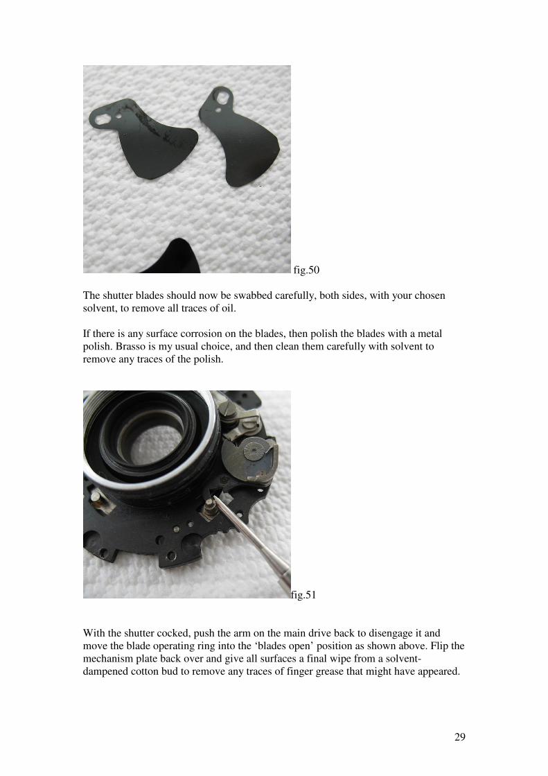
fig.50
The shutter blades should now be swabbed carefully, both sides, with your chosen
solvent, to remove all traces of oil.
If there is any surface corrosion on the blades, then polish the blades with a metal
polish. Brasso is my usual choice, and then clean them carefully with solvent to
remove any traces of the polish.
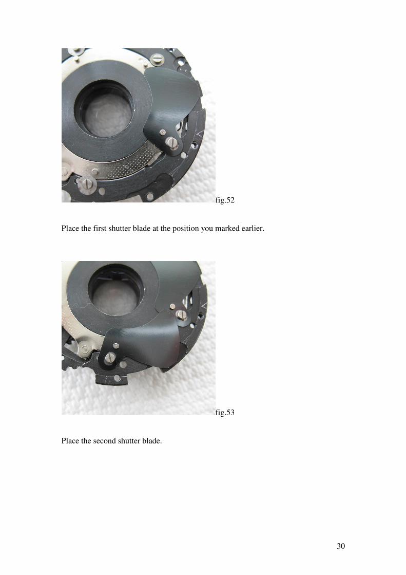
fig.51
With the shutter cocked, push the arm on the main drive back to disengage it and
move the blade operating ring into the ‘blades open’ position as shown above. Flip the
mechanism plate back over and give all surfaces a final wipe from a solvent-
dampened cotton bud to remove any traces of finger grease that might have appeared.
30
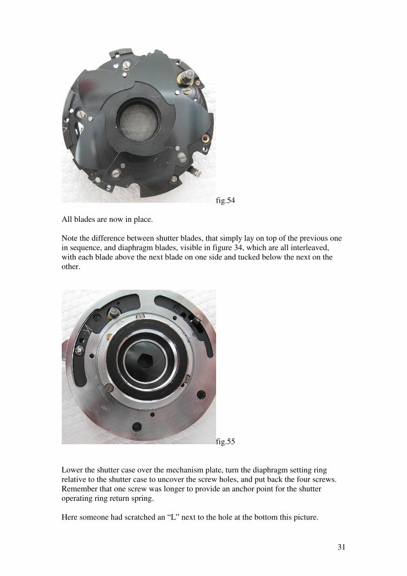
fig.52
Place the first shutter blade at the position you marked earlier.
fig.53
Place the second shutter blade.
31
fig.54
All blades are now in place.
Note the difference between shutter blades, that simply lay on top of the previous one
in sequence, and diaphragm blades, visible in figure 34, which are all interleaved,
with each blade above the next blade on one side and tucked below the next on the
other.
fig.55
Lower the shutter case over the mechanism plate, turn the diaphragm setting ring
relative to the shutter case to uncover the screw holes, and put back the four screws.
Remember that one screw was longer to provide an anchor point for the shutter
operating ring return spring.
Here someone had scratched an “L” next to the hole at the bottom this picture.
32
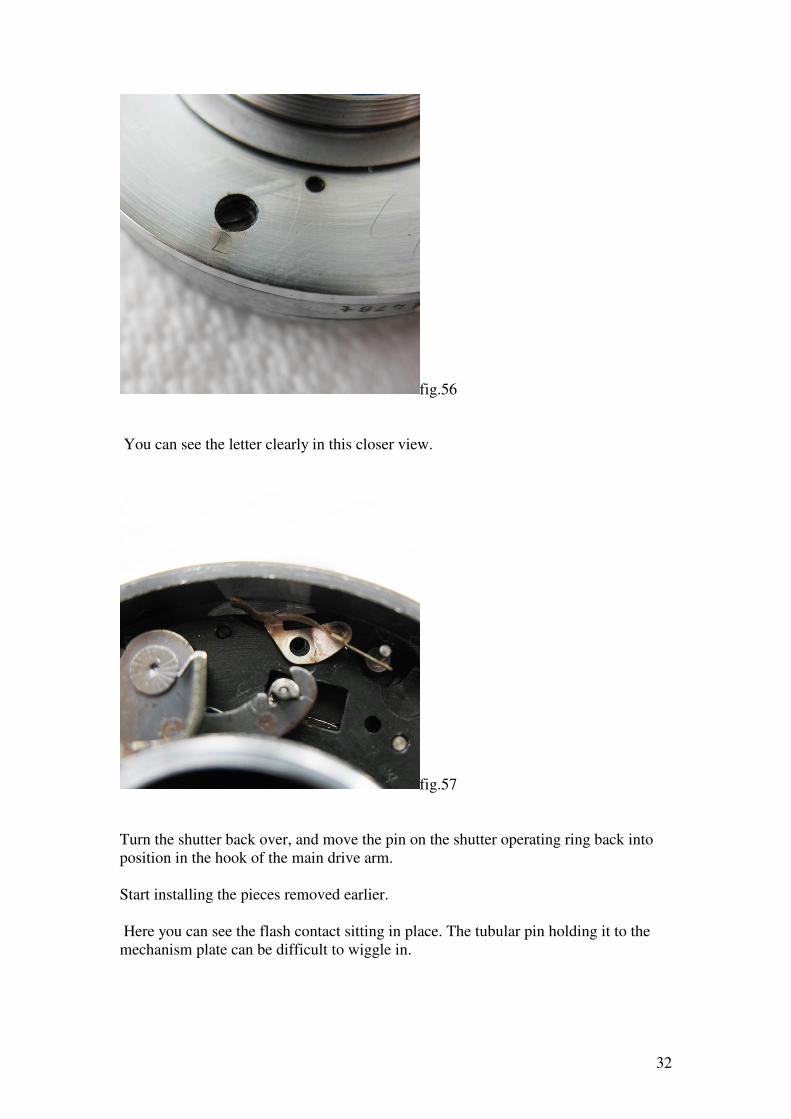
fig.56
You can see the letter clearly in this closer view.
fig.57
Turn the shutter back over, and move the pin on the shutter operating ring back into
position in the hook of the main drive arm.
Start installing the pieces removed earlier.
Here you can see the flash contact sitting in place. The tubular pin holding it to the
mechanism plate can be difficult to wiggle in.
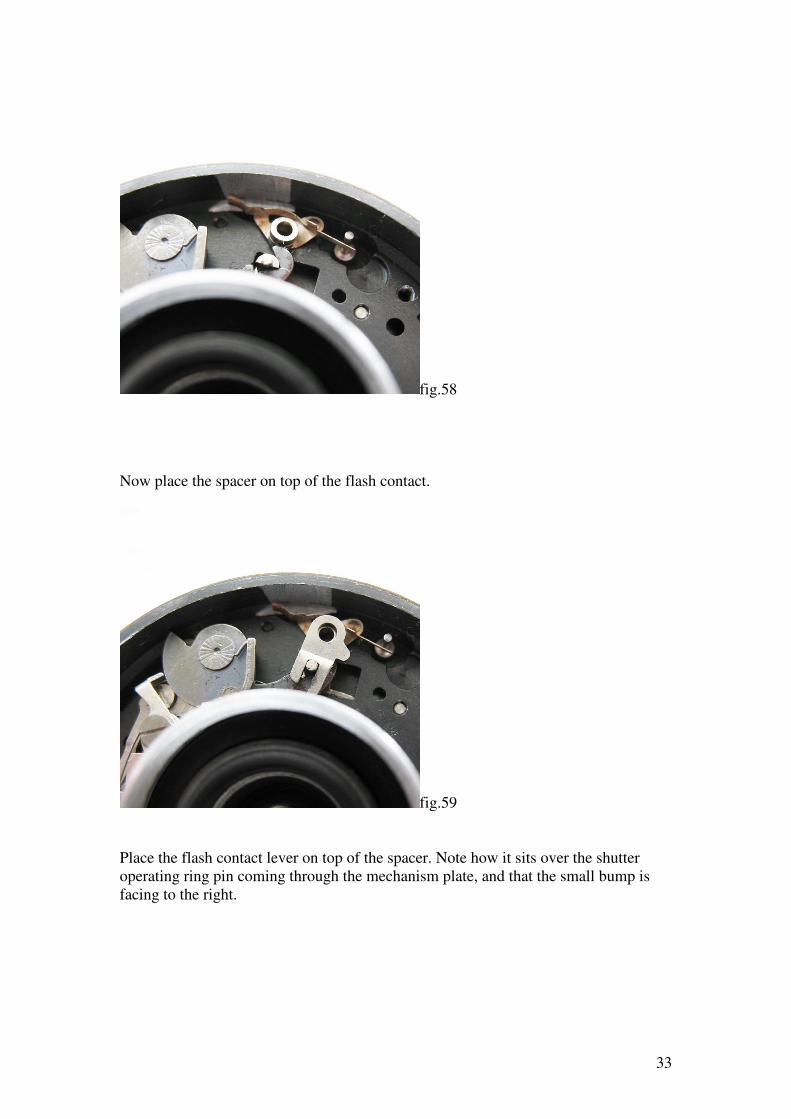
33
fig.58
Now place the spacer on top of the flash contact.
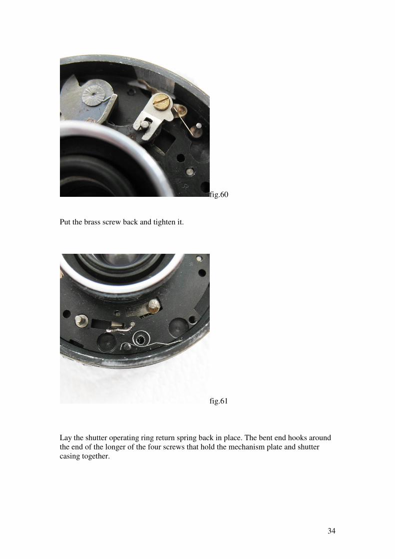
fig.59
Place the flash contact lever on top of the spacer. Note how it sits over the shutter
operating ring pin coming through the mechanism plate, and that the small bump is
facing to the right.
34
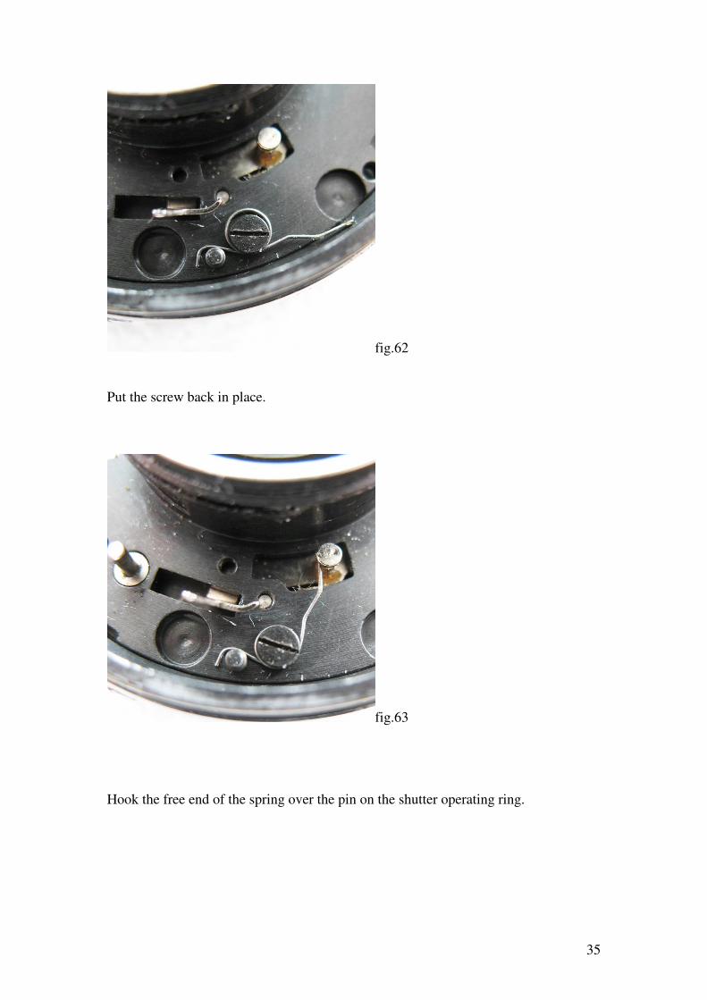
fig.60
Put the brass screw back and tighten it.
fig.61
Lay the shutter operating ring return spring back in place. The bent end hooks around
the end of the longer of the four screws that hold the mechanism plate and shutter
casing together.
35
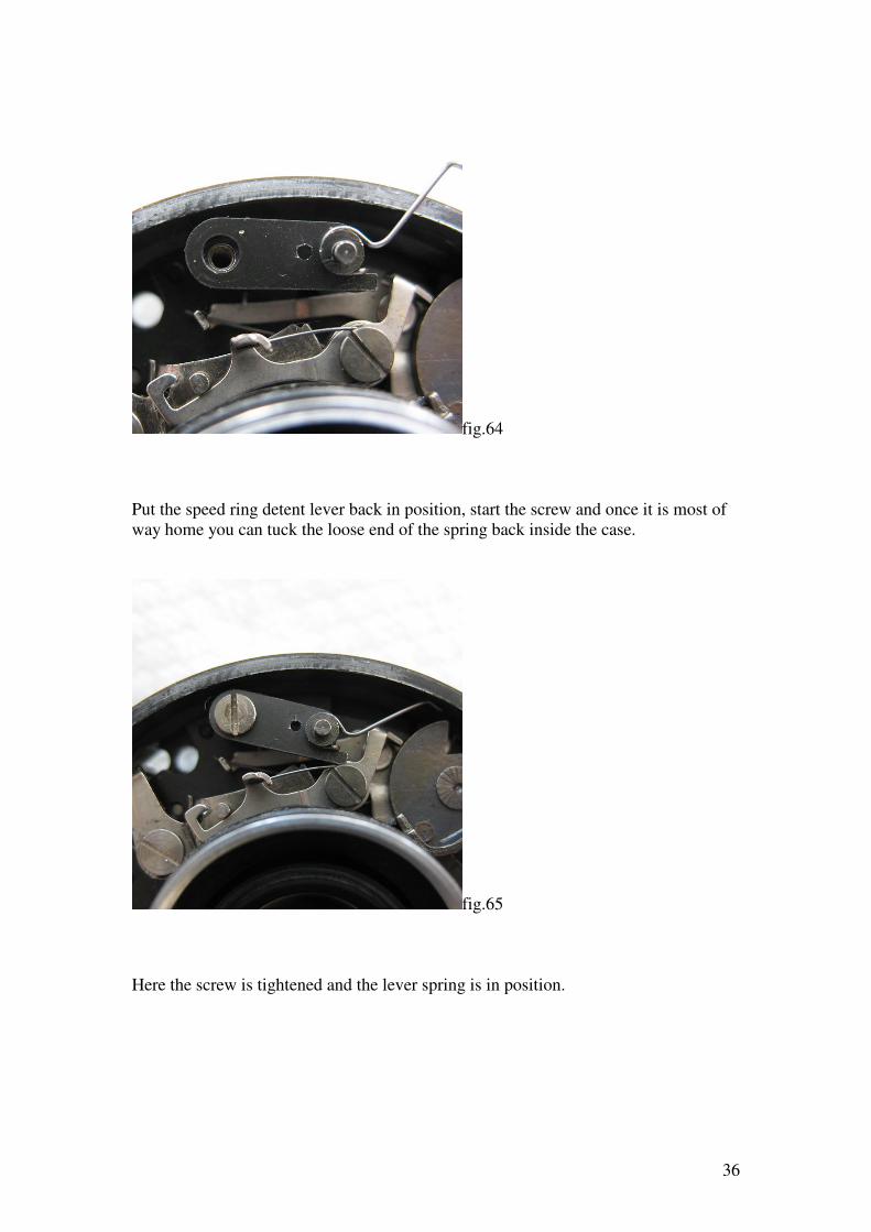
fig.62
Put the screw back in place.
fig.63
Hook the free end of the spring over the pin on the shutter operating ring.
36
fig.64
Put the speed ring detent lever back in position, start the screw and once it is most of
way home you can tuck the loose end of the spring back inside the case.
fig.65
Here the screw is tightened and the lever spring is in position.
37
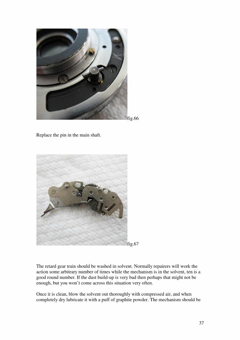
fig.66
Replace the pin in the main shaft.
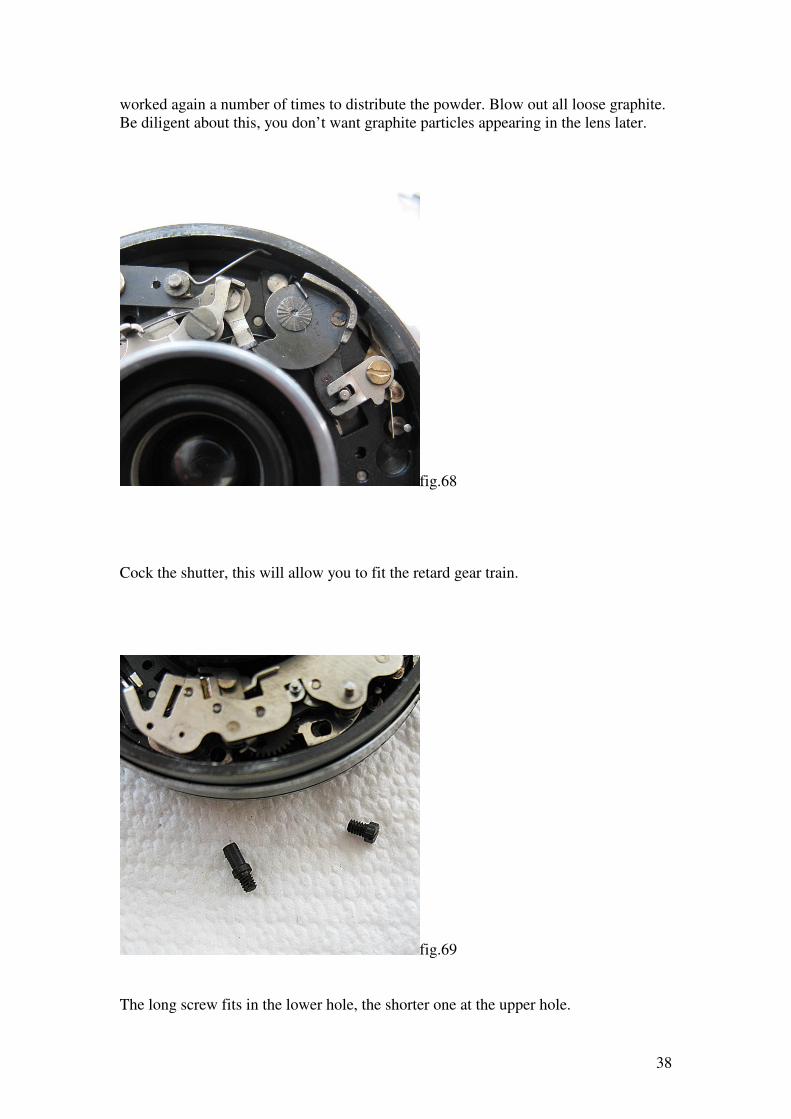
fig.67
The retard gear train should be washed in solvent. Normally repairers will work the
action some arbitrary number of times while the mechanism is in the solvent, ten is a
good round number. If the dust build-up is very bad then perhaps that might not be
enough, but you won’t come across this situation very often.
Once it is clean, blow the solvent out thoroughly with compressed air, and when
completely dry lubricate it with a puff of graphite powder. The mechanism should be
38
worked again a number of times to distribute the powder. Blow out all loose graphite.
Be diligent about this, you don’t want graphite particles appearing in the lens later.
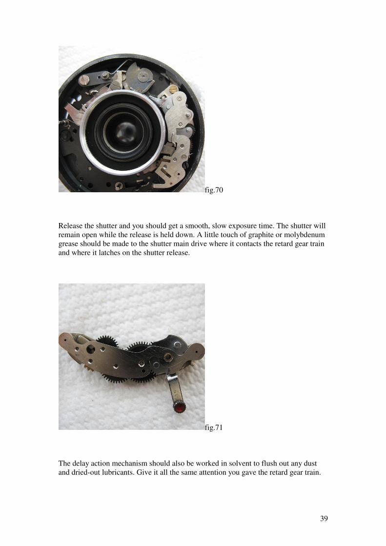
fig.68
Cock the shutter, this will allow you to fit the retard gear train.
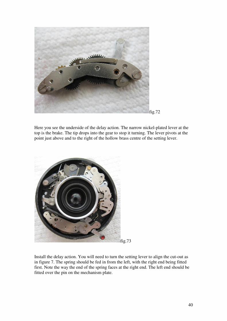
fig.69
The long screw fits in the lower hole, the shorter one at the upper hole.
39
fig.70
Release the shutter and you should get a smooth, slow exposure time. The shutter will
remain open while the release is held down. A little touch of graphite or molybdenum
grease should be made to the shutter main drive where it contacts the retard gear train
and where it latches on the shutter release.
fig.71
The delay action mechanism should also be worked in solvent to flush out any dust
and dried-out lubricants. Give it all the same attention you gave the retard gear train.
40
fig.72
Here you see the underside of the delay action. The narrow nickel-plated lever at the
top is the brake. The tip drops into the gear to stop it turning. The lever pivots at the
point just above and to the right of the hollow brass centre of the setting lever.
fig.73
Install the delay action. You will need to turn the setting lever to align the cut-out as
in figure 7. The spring should be fed in from the left, with the right end being fitted
first. Note the way the end of the spring faces at the right end. The left end should be
fitted over the pin on the mechanism plate.
41
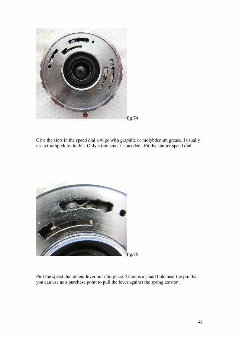
fig.74
Give the slots in the speed dial a wipe with graphite or molybdenum grease. I usually
use a toothpick to do this. Only a thin smear is needed. Fit the shutter speed dial.
fig.75
Pull the speed dial detent lever out into place. There is a small hole near the pin that
you can use as a purchase point to pull the lever against the spring tension.
42
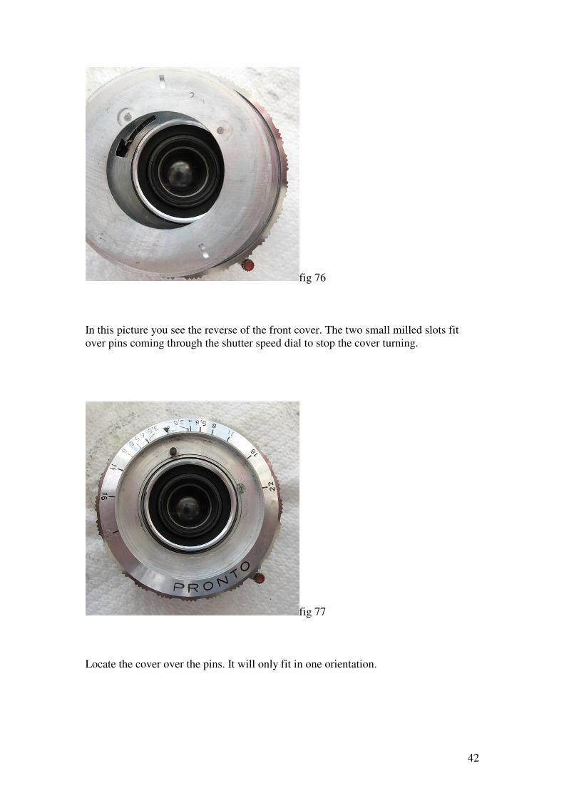
fig 76
In this picture you see the reverse of the front cover. The two small milled slots fit
over pins coming through the shutter speed dial to stop the cover turning.
fig 77
Locate the cover over the pins. It will only fit in one orientation.
43
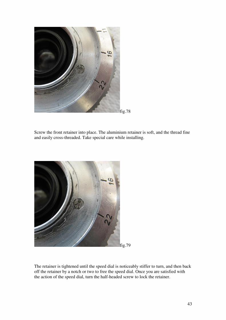
fig.78
Screw the front retainer into place. The aluminium retainer is soft, and the thread fine
and easily cross-threaded. Take special care while installing.
fig.79
The retainer is tightened until the speed dial is noticeably stiffer to turn, and then back
off the retainer by a notch or two to free the speed dial. Once you are satisfied with
the action of the speed dial, turn the half-headed screw to lock the retainer.
44
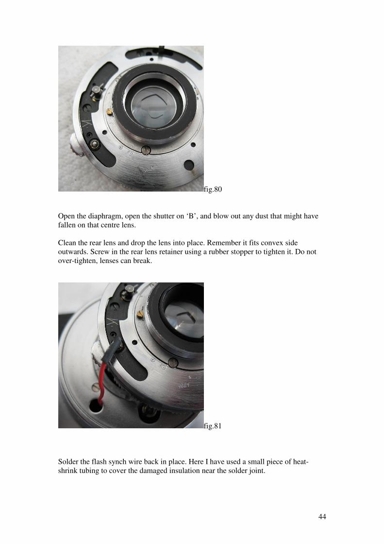
fig.80
Open the diaphragm, open the shutter on ‘B’, and blow out any dust that might have
fallen on that centre lens.
Clean the rear lens and drop the lens into place. Remember it fits convex side
outwards. Screw in the rear lens retainer using a rubber stopper to tighten it. Do not
over-tighten, lenses can break.
fig.81
Solder the flash synch wire back in place. Here I have used a small piece of heat-
shrink tubing to cover the damaged insulation near the solder joint.
45
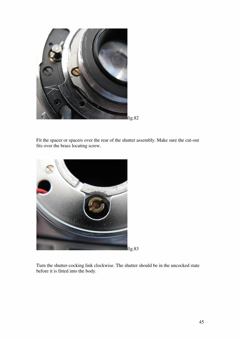
fig.82
Fit the spacer or spacers over the rear of the shutter assembly. Make sure the cut-out
fits over the brass locating screw.
fig.83
Turn the shutter-cocking link clockwise. The shutter should be in the uncocked state
before it is fitted into the body.
46
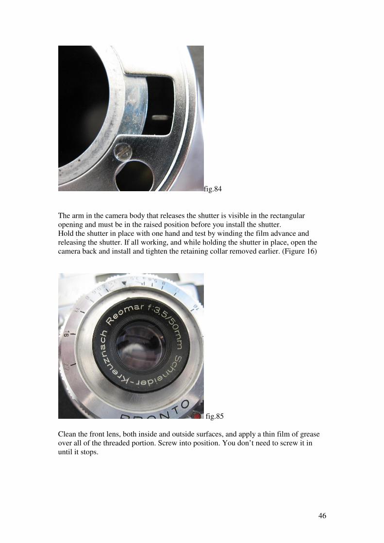
fig.84
The arm in the camera body that releases the shutter is visible in the rectangular
opening and must be in the raised position before you install the shutter.
Hold the shutter in place with one hand and test by winding the film advance and
releasing the shutter. If all working, and while holding the shutter in place, open the
camera back and install and tighten the retaining collar removed earlier. (Figure 16)
fig.85
Clean the front lens, both inside and outside surfaces, and apply a thin film of grease
over all of the threaded portion. Screw into position. You don’t need to screw it in
until it stops.
47
To set the focus ideally you should have the camera set on a tripod for convenience. A
ground glass screen, the same width as the film, is held in position in the film gate,
matt side to the lens.
A nice alternative to a plain ground glass screen is a focus screen taken from a
wrecked 35mm SLR camera. Many have a split-image in the centre of the screen,
which makes setting the focus even easier. The screen must sit on the bright
aluminium film rails. As these screens are usually much narrower than a film, this
means it will have to sit at an angle unless you cut the ends off to allow it sit neatly on
the rails when turned 90 degrees.
As a not-so-nice alternative to a ground glass screen, you can get by using a piece of
matt finish, translucent sticky tape stretched tightly across the film gate top to bottom
on the bright aluminium rails, not the outer black finished section.
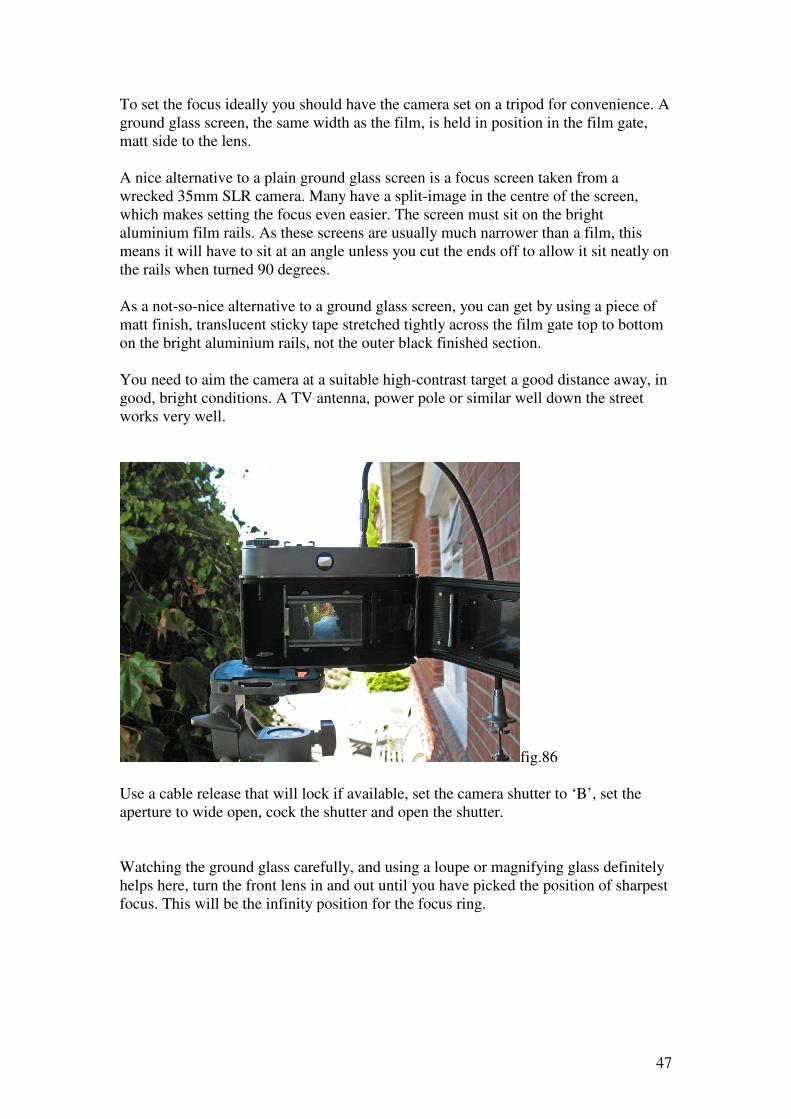
You need to aim the camera at a suitable high-contrast target a good distance away, in
good, bright conditions. A TV antenna, power pole or similar well down the street
works very well.
fig.86
Use a cable release that will lock if available, set the camera shutter to ‘B’, set the
aperture to wide open, cock the shutter and open the shutter.
Watching the ground glass carefully, and using a loupe or magnifying glass definitely
helps here, turn the front lens in and out until you have picked the position of sharpest
focus. This will be the infinity position for the focus ring.
48
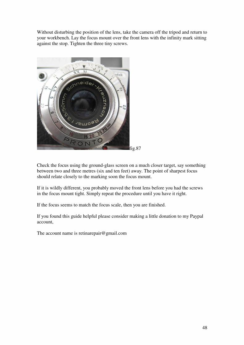
Without disturbing the position of the lens, take the camera off the tripod and return to
your workbench. Lay the focus mount over the front lens with the infinity mark sitting
against the stop. Tighten the three tiny screws.
fig.87
Check the focus using the ground-glass screen on a much closer target, say something
between two and three metres (six and ten feet) away. The point of sharpest focus
should relate closely to the marking soon the focus mount.
If it is wildly different, you probably moved the front lens before you had the screws
in the focus mount tight. Simply repeat the procedure until you have it right.
If the focus seems to match the focus scale, then you are finished.
If you found this guide helpful please consider making a little donation to my Paypal
account,
The account name is [email protected]