retaining wall and support system for deep … of retaining wall and support system for deep...
TRANSCRIPT
Design of Retaining Wall and Support System for Deep BasementDeep Basement
Ir. TAN Yean ChinG&P Geotechnics Sdn Bhd
www.gnpgroup.com.my
March, 2014
INTRODUCTION
� Deep basement construction� Urban areas for parking space� Infrastructures, e.g. KVMRT
G&P Geotechnics Sdn Bhd
� Infrastructures, e.g. KVMRT
� Risk associated with deep basement construction high!

FAILURES of DEEP EXCAVATION

FAILURES of DEEP EXCAVATION
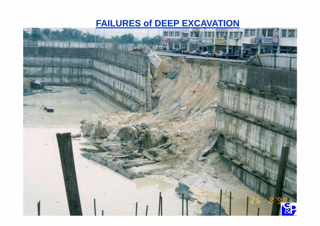
FAILURES of DEEP EXCAVATION
SOIL PARAMETERSPARAMETERS

SOIL PARAMETERS
� Some important soil parameters related to retaining wall and support system design:
G&P Geotechnics Sdn Bhd
system design:�Shear strength parameters (su, φ’ & c’)�Soil permeability�Soil stiffness

SOIL PARAMETERS
� Shear strength parameters (φ’ and c’)�Commonly obtained from CIU for effective
stress strength parameters
G&P Geotechnics Sdn Bhd
stress strength parameters�Commonly obtained using in -situ test
methods (e.g. field vane shear test) for total stress strength parameters, su
�Finite element analysis – requires proper understanding of the constitutive soil models

SOIL PARAMETERS
� Soil permeability� Important in order to choose modelling in
drained or undrained condition
G&P Geotechnics Sdn Bhd
drained or undrained condition� In-situ tests (rising, falling or constant head)
recommended�Values obtained from tests should always be
compared to published values (e.g. BS8004)

G&P Geotechnics Sdn Bhd
BS8004: 1986

SOIL PARAMETERS
� Soil stiffness� Important parameters for retaining wall design
BUT difficult to obtain reliablyIn Malaysia, sometimes based on empirical
G&P Geotechnics Sdn Bhd
� In Malaysia, sometimes based on empirical correlations
�Laboratory tests unreliable and values obtained significantly smaller than appropriate values for retaining wall design
�Designer should be aware of small-strainnature of retaining wall design

G&P Geotechnics Sdn Bhd
SOIL PARAMETERS
� Soil stiffness�Seismic tests or seismic piezocone appears
promising – future direction
G&P Geotechnics Sdn Bhd
promising – future direction�Basis of empirical correlations should be
understood – e.g. local soil conditions, constitutive model used, etc.
�Example, correlations in Kenny Hill formation using hardening soil model of PLAXIS software

DESIGN OF RETAINING WALLSRETAINING WALLS
DESIGN CONSIDERATIONS
� Overall stability� Basal heave failure� Hydraulic failure
G&P Geotechnics Sdn Bhd
� Hydraulic failure� Axial stability� Finite element analysis� Ground movement associated with
excavation
OVERALL STABILITY
� To ensure sufficient wall embedment�Overturning of wall and overall slope
stability
G&P Geotechnics Sdn Bhd
stability�Adequate factors of safety (e.g. 1.4 for
high-risk-to-life structures)

G&P Geotechnics Sdn Bhd
EUROCODE 7

DESIGN CONSIDERATIONS
� Overall stability� Basal heave failure� Hydraulic failure
G&P Geotechnics Sdn Bhd
� Hydraulic failure� Axial stability� Finite element analysis� Ground movement associated with
excavation

BASAL HEAVE FAILURE
� Critical for deep excavation in soft ground� Analogous to bearing capacity failure , only in
reverse
G&P Geotechnics Sdn Bhd
� Available methods:� Terzaghi (1943) – shallow and wide excavations� Bjerrum & Eide (1956) – deep and narrow and
excavations� Moment equilibrium - adequate for routine design
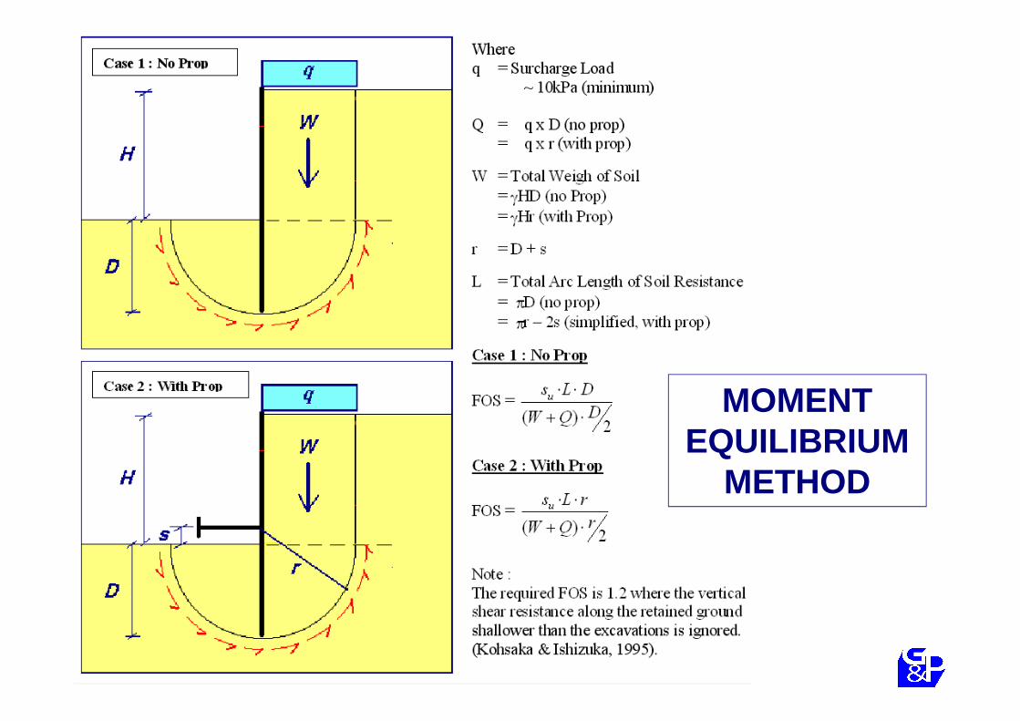
MOMENT EQUILIBRIUM
METHOD

BASAL HEAVE FAILURE
� Required factor of safety for moment equilibrium method�1.2 (Kohsaka & Ishizuka, 1995)
G&P Geotechnics Sdn Bhd
�1.2 (Kohsaka & Ishizuka, 1995)�Vertical shear resistance along retained
ground shallower than the excavation is ignored

DESIGN CONSIDERATIONS
� Overall stability� Basal heave failure� Hydraulic failure
G&P Geotechnics Sdn Bhd
� Hydraulic failure� Axial stability� Finite element analysis� Ground movement associated with
excavation

HYDRAULIC FAILURE
� Base instability caused by piping�Seepage due to high groundwater level
G&P Geotechnics Sdn Bhd
� Available methods�Terzaghi’s method�Critical hydraulic gradient method
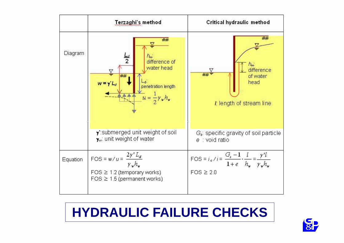
HYDRAULIC FAILURE CHECKS

HYDRAULIC FAILURE
� Terzaghi’s method recommended�Based on latest research by Tanaka &
Verruijt (1999)
G&P Geotechnics Sdn Bhd
Verruijt (1999)�Factor of safety required – 1.2 to 1.5
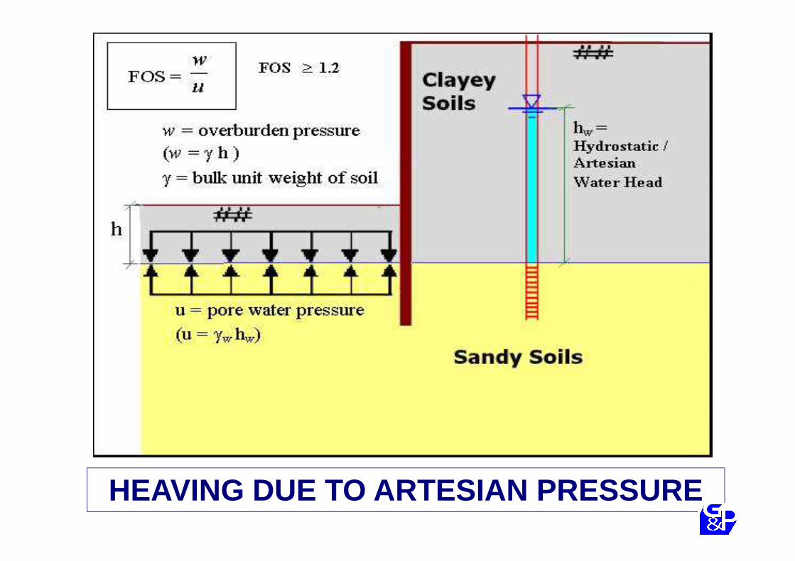
HEAVING DUE TO ARTESIAN PRESSURE

HYDRAULIC FAILURE
� Heaving due to artesian pressure
�Factor of safety – 1.0 to 1.2
G&P Geotechnics Sdn Bhd
�Factor of safety – 1.0 to 1.2�Smaller FOS sufficient as it did not
consider shear strength or adhesion strength of the ground and retaining wall

DESIGN CONSIDERATIONS
� Overall stability� Basal heave failure� Hydraulic failure
G&P Geotechnics Sdn Bhd
� Hydraulic failure� Axial stability� Finite element analysis� Ground movement associated with
excavation

AXIAL STABILITY
� Simple check but is often overlooked
� Factor of safety
G&P Geotechnics Sdn Bhd
� Factor of safetyrequired – 2.0

FINITE ELEMENT ANALYSISANALYSIS

FINITE ELEMENT ANALYSIS
� Soil-structure interaction important for deep basement retaining wall design
� Commercial finite element software easily
G&P Geotechnics Sdn Bhd
� Commercial finite element software easily available and very user friendly (e.g. PLAXIS, CRISP, etc.)
� Understanding and proper useimportant!!!

Results using the same soil parameters and same software by different people!

FINITE ELEMENT ANALYSIS
� Some important considerations in FEM:�Locations of the boundaries of the problem�Details of mesh
G&P Geotechnics Sdn Bhd
�Modelling of stages of construction�Modelling of interfaces�Use of suitable constitutive soil model�Use of appropriate soil parameters, especially
empirical parameters

GEOMETRICAL DATA
� Provision for over-excavation � for cantilever walls - 10% of the wall height above
excavation level, limited to a maximum of 0.5m� for a supported walls - 10% of the distance between
G&P Geotechnics Sdn Bhd
� for a supported walls - 10% of the distance between the lowest support and the excavation level, limited to a maximum of 0.5m
� Can be reduced when excavation surface can be controlled reliably throughout the excavation works
GEOMETRICAL DATA
� Water levels�Flood level should be taken into consideration
for flood prone areas
G&P Geotechnics Sdn Bhd
for flood prone areas
� Surcharge�Minimum surcharge of 10kPa – for
construction loads and unforeseen circumstances

CONSTITUTIVE SOIL MODELS
� Various constitutive soil models, e.g. Mohr-Coulomb, Cam Clay, Hardening Soil, Soft Soil, etc.
G&P Geotechnics Sdn Bhd
Soft Soil, etc.�Proper understanding and limitations of
each model important!� Incorrect use of soil models in Nicoll Highway!

Overestimation of shear strength!!!
Stress path of real soil
Stress path using Mohr-Coulomb
model
strength!!!

FEM ANALYSIS OF LIMIT STATE
� Eurocodes have replaced British Standards
G&P Geotechnics Sdn Bhd
� Current design of retaining wall for deep basement mostly based on “working state design ”

FEM ANALYSIS OF LIMIT STATE
� Three (3) schemes to perform limit states design using FEM:
(A) Perform all the calculations with design (factored) values of ground and action parameters
G&P Geotechnics Sdn Bhd
values of ground and action parameters(B) Simulate the whole stress history using ground
parameters at characteristic levels- check the safety at the relevant stages
(C) Simulate the whole stress history using ground parameters at characteristic levels and multiplying these values by the load factor (which then in fact acts as a model factor on the effects of actions).
FEM ANALYSIS OF LIMIT STATE
� Important to evaluate limit state:�Part of the reason for factors of safety is to
cover human error
G&P Geotechnics Sdn Bhd
cover human error�Limit state analyses investigate unrealistic
states , especially in the Ultimate Limit State (ULS) analysis
TO ENSURE THAT LIMIT STATE IS SUFFICIENTLY UNLIKELY TO OCCUR

GROUND MOVEMENT ASSOCIATED WITH EXCAVATIONEXCAVATION

GROUND MOVEMENT
� Deep excavation include a substantial component of horizontal strain
G&P Geotechnics Sdn Bhd
� Damage estimation should include both angular distortion and horizontal strain
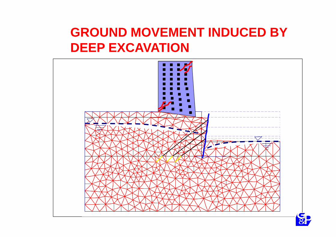
GROUND MOVEMENT INDUCED BY DEEP EXCAVATION

GROUND MOVEMENT INDUCED BY DEEP EXCAVATION
G&P Geotechnics Sdn Bhd

Gap
GROUND MOVEMENT INDUCED BY DEEP EXCAVATION
G&P Geotechnics Sdn Bhd
Gap(75mm)
Void (150mm)
Settlement
G&P Geotechnics Sdn Bhd
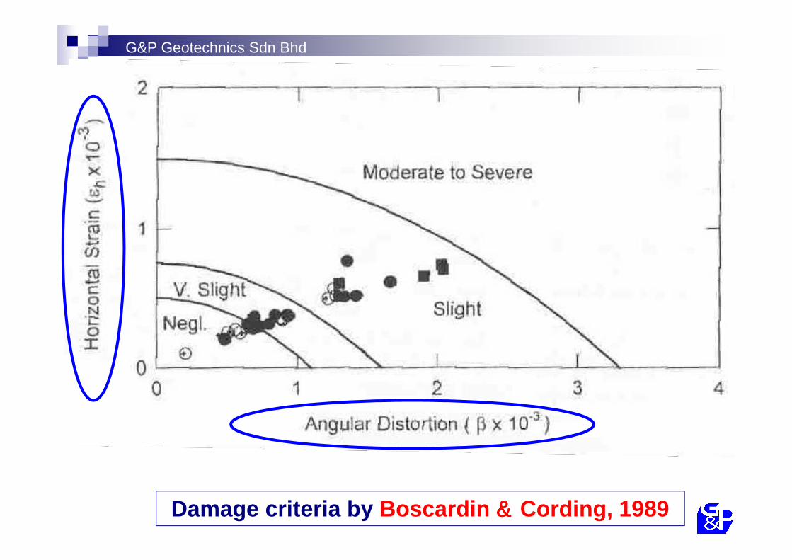
Damage criteria by Boscardin &&&& Cording, 1989

CATEGORY ANGULAR DISTORTION,
β (x 10-3)
HORIZONTAL STRAIN, εh (x 10-3)
Negligible < ~ 1.1 > 0.5
Very slight ~ 1.1 < β < ~ 1.6 0.5 < εh < 0.75
G&P Geotechnics Sdn Bhd
Very slight ~ 1.1 < β < ~ 1.6 0.5 < εh < 0.75
Slight ~ 1.6 < β < ~ 3.3 0.75 < εh < 1.5
Moderate ~ 3.3 < β < ~ 6.7 1.5 < εh < 3.0
Severe > ~ 6.7 > 3.0

Before excavation
After excavation
h
∆∆∆∆β = β = β = β = ∆∆∆∆/Lεεεε = h/L
G&P Geotechnics Sdn Bhd
εεεεh = h/LL = length of building
E.g.
Building length = 10m
Allowable lateral movement = 15mm
(εεεεh = 1.5 x 10⁻³)
CASE HISTORIES
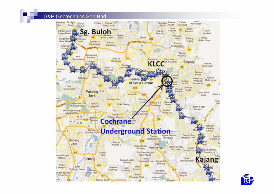
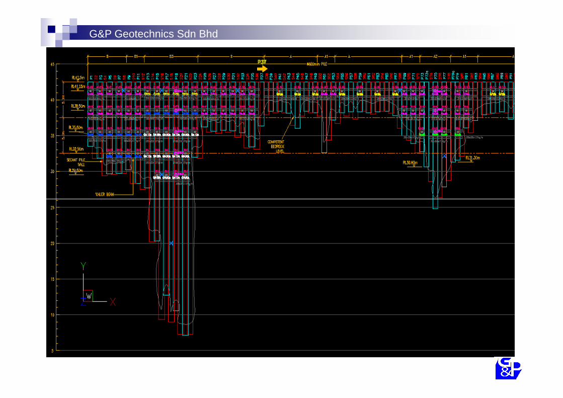
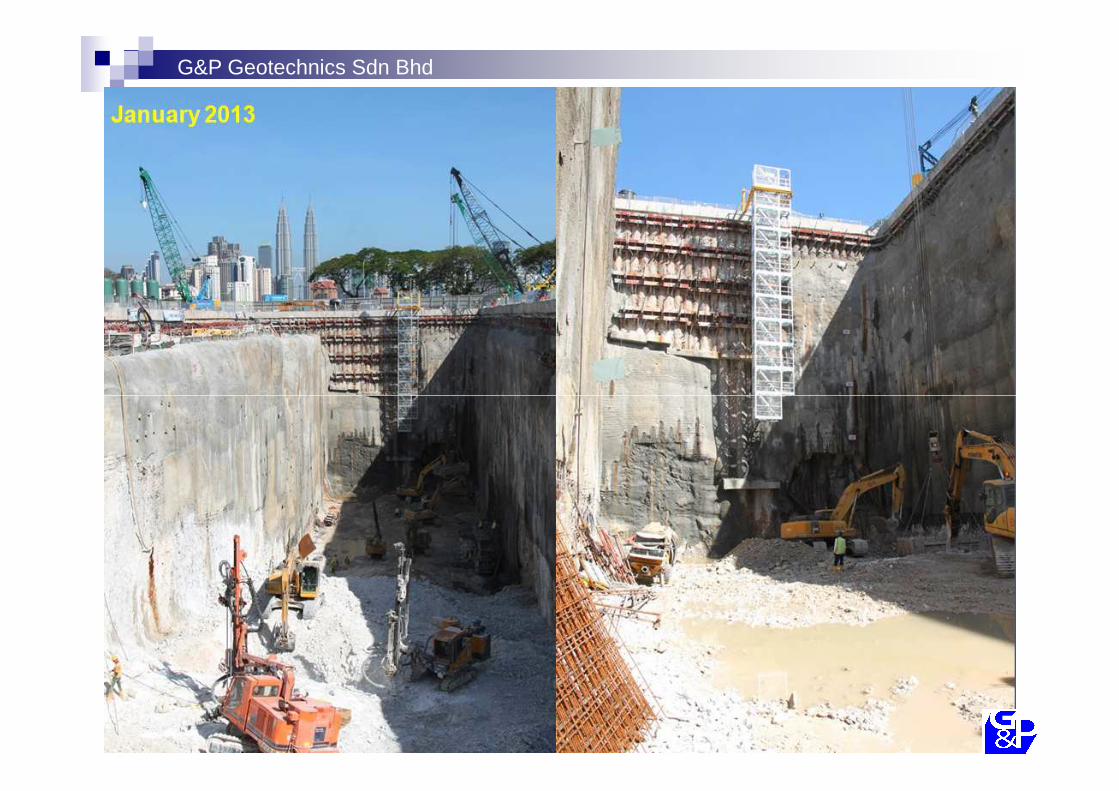
Case History 1 :32m Deep Excavation for KVMRT – Blue LineKVMRT – Blue Line(Cochrane Underground Station)
G&P Geotechnics Sdn Bhd

G&P Geotechnics Sdn Bhd
G&P Geotechnics Sdn Bhd

G&P Geotechnics Sdn Bhd

G&P Geotechnics Sdn Bhd
G&P Geotechnics Sdn Bhd

G&P Geotechnics Sdn Bhd
G&P Geotechnics Sdn Bhd

G&P Geotechnics Sdn Bhd

G&P Geotechnics Sdn Bhd
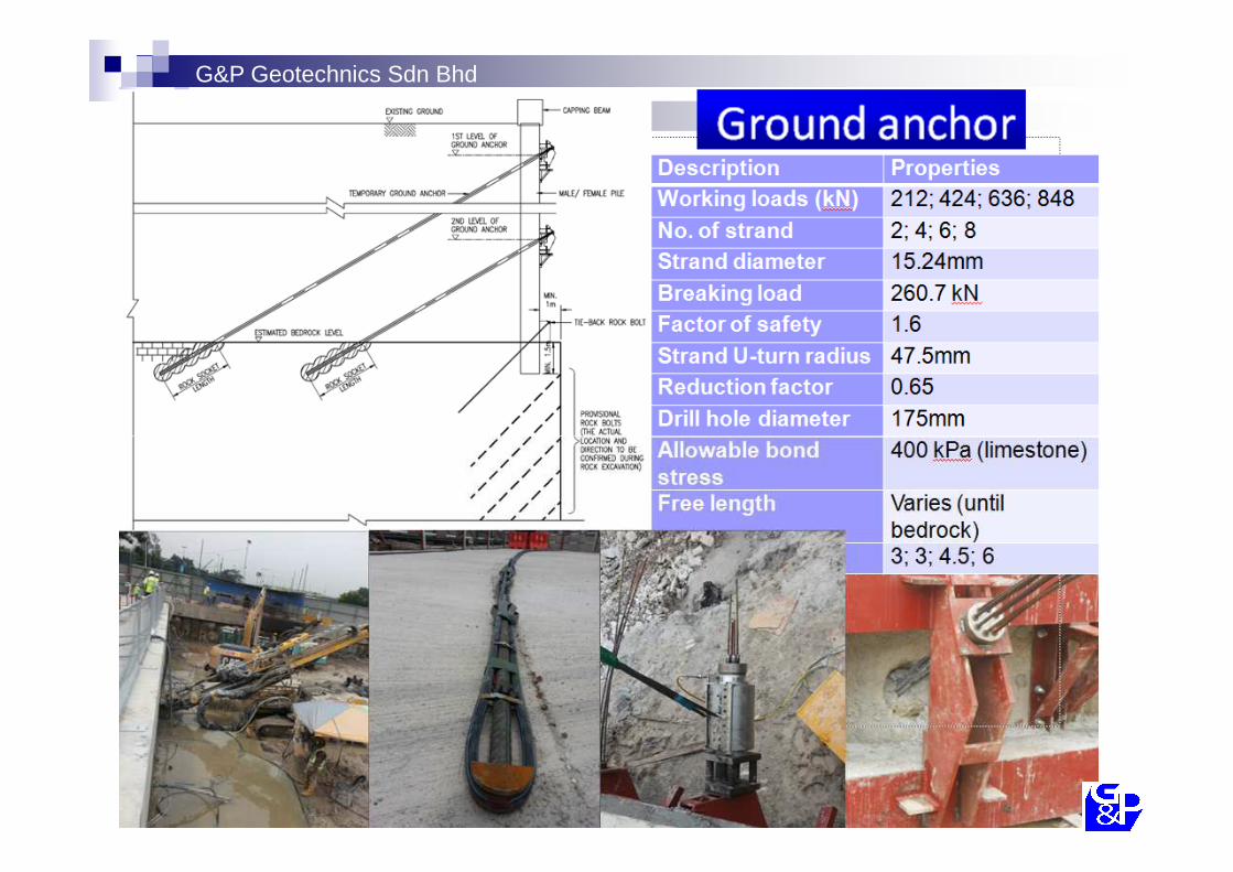
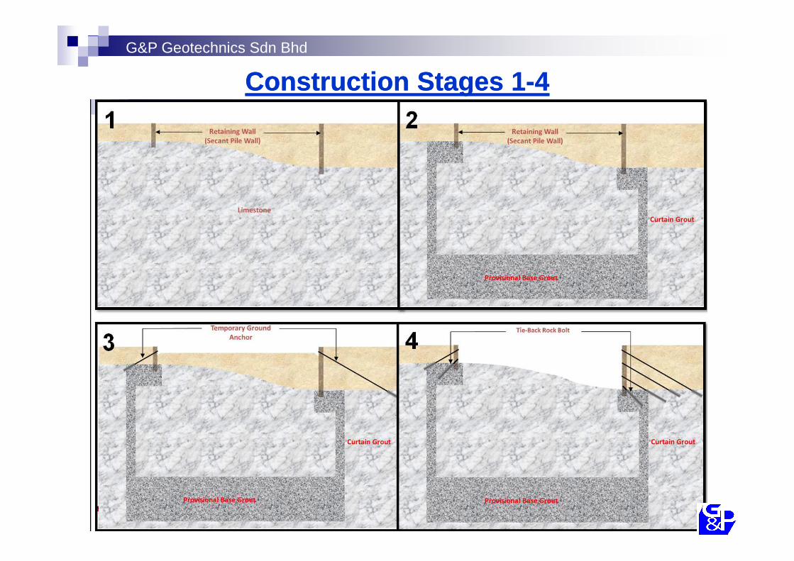
Rock Rock StabilisationStabilisation MeasuresMeasures
G&P Geotechnics Sdn Bhd
Construction Stages 1Construction Stages 1--44

G&P Geotechnics Sdn Bhd
Construction Stages 5Construction Stages 5--88

G&P Geotechnics Sdn Bhd
G&P Geotechnics Sdn Bhd

G&P Geotechnics Sdn Bhd

G&P Geotechnics Sdn Bhd

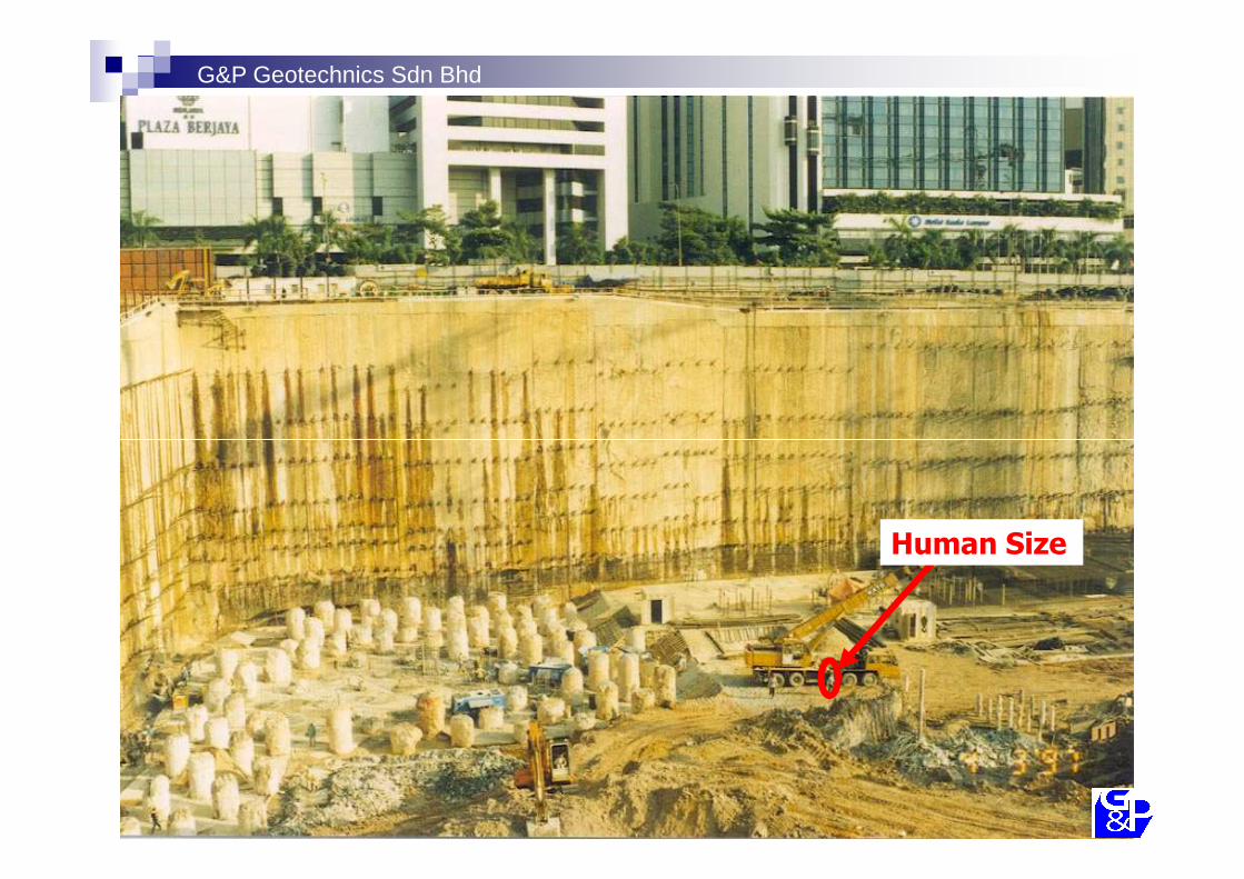
Case History 2 :28.5m Deep Excavation for Berjaya Times Square, Berjaya Times Square, Jalan Imbi

Berjaya Times Square
� Excavated depth24.5m - 28.5m (6-level basement)
� Retaining wall
G&P Geotechnics Sdn Bhd
1.2m thick diaphragm walls
� Support systemPrestressed Ground Anchors
G&P Geotechnics Sdn Bhd
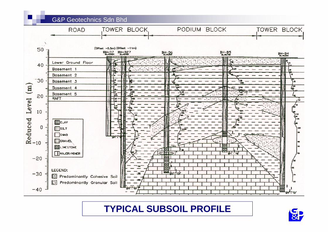
TYPICAL SUBSOIL PROFILE

G&P Geotechnics Sdn Bhd
FINITE ELEMENT MODELLING

G&P Geotechnics Sdn Bhd
-10 0 10 20 30 40Wall Relative Lateral Displacement (mm)
-50
-40
-30
-20
-10
0
Dep
th (m
)
Measured ProfileFEM Back Analysed
Excavate to R.L.35.0m
Stage 1
-10 0 10 20 30 40Wall Relative Lateral Displacement (mm)
-50
-40
-30
-20
-10
0
Dep
th (m
)
Excavate to R.L.31.0m
Stage 2
-10 0 10 20 30 40Wall Relative Lateral Displacement (mm)
-40
-30
-20
-10
0
Dep
th (m
)
Stage 3
Excavate to R.L.27.0m
-50-10 0 10 20 30 40
Wall Relative Lateral Displacement (mm)
-50
-40
-30
-20
-10
0
Dep
th (m
)
Stage 4
Excavate to R.L.22.5m
-10 0 10 20 30 40Wall Relative Lateral Displacement (mm)
-50
-40
-30
-20
-10
0
Dep
th (m
)
Stage 4
Excavate to R.L.18.5m
-10 0 10 20 30 40Wall Relative Lateral Displacement (mm)
-50
-40
-30
-20
-10
0
Dep
th (m
)
Stage 6
Excavate to R.L.16.7m
WALL A

G&P Geotechnics Sdn Bhd
Berjaya Times Square
� Hardening Soil Model of PLAXIS able to model the problem sufficiently accurate
� From FEM back-analysis, the correlations between soil stiffness (E’) and SPT ‘N’ as follows:�E’ = 2000*SPT‘N’(kN/m 2)�E’ur = 3*E’ = 6000*SPT’N’(kN/m 2)
G&P Geotechnics Sdn Bhd
Human Size

Case History 3 :30m Deep Excavation for Solaris Dutamas , KLSolaris Dutamas , KL

G&P Geotechnics Sdn Bhd
Solaris Dutamas

G&P Geotechnics Sdn Bhd

G&P Geotechnics Sdn Bhd
Typical Simplified
Borelog ProfilesBorelog Profiles

Original CBP Wall with
Temporary Ground Anchors
Initial basement wall
G&P Geotechnics Sdn Bhd
Anchors
Temporary Ground Anchor

Original CBP Wall with
Temporary Ground Anchors
G&P Geotechnics Sdn Bhd
Anchors
G&P Geotechnics Sdn Bhd

G&P Geotechnics Sdn Bhd

G&P Geotechnics Sdn Bhd

G&P Geotechnics Sdn Bhd
Typical finite element model (PLAXIS)

Measured
G&P Geotechnics Sdn Bhd
Predicted ground movement
Measured

� Soil nails subjected to verification and proof test based on FHWA, 1998�Criteria on creep movement�Criteria on theoretical elongation
� Based on verification tests on preliminary soil nails�Ground -grout bond = 3 to 5*SPT -N (in kPa)

THANK YOU
Y.C. TANG&P Geotechnics Sdn Bhdwww.gnpgroup.com.my
March, 2014
Q &&&& A