ret installation instructions
TRANSCRIPT

8/12/2019 RET Installation Instructions
http://slidepdf.com/reader/full/ret-installation-instructions 1/20
HOJA DE INSTRUCCIONES(INSTRUCTIONS SHEET)
DOC.Nº: IS-146
ED.: 2 REV.: 0
FECHA: 27/06/2012
Instrucciones de instalación RETRET installation instructions
KAVVERI TELECOM se reserva el derecho de modificar este documento sin previo aviso.KAVVERI TELECOM will reserve the right to modify this document without previous notice.KAVVERI TELECOM se reserve le droit de modifier ce document sans notification préable. 1/20
TO AVOID DAMAGE TO THE DEVICE, PLEASE, CAREFULLYFOLLOW CONNECTION INSTRUCTIONS DESCRIBED IN ITEM 3.2
OF THIS MANUAL
PARA EVITAR DETERIOROS EN EL DISPOSITIVO SIGA ATENTAMENTE LAS INSTRUCCIONES DE CONEXIÓN INDICADAS
EN EL PUNTO 3.2 DE ESTE MANUAL
ATENCIÓN
CAUTION!

8/12/2019 RET Installation Instructions
http://slidepdf.com/reader/full/ret-installation-instructions 2/20
HOJA DE INSTRUCCIONES(INSTRUCTIONS SHEET)
DOC.Nº: IS-146
ED.: 2 REV.: 0
FECHA: 27/06/2012
Instrucciones de instalación RETRET installation instructions
KAVVERI TELECOM se reserva el derecho de modificar este documento sin previo aviso.KAVVERI TELECOM will reserve the right to modify this document without previous notice.KAVVERI TELECOM se reserve le droit de modifier ce document sans notification préable. 2/20
INDICE / Index Pag.
ESPAÑOL
1.- CONTENIDO DE LA CAJA .................................................................................................... 3
2.- IDENTIFICACIÓN DEL INTERFAZ MECÁNICO DE LA ANTENA PREPARADO PARA LA CONEXIÓNDEL RET. ........................................................................................................................... 4
3.- CONEXIÓN DEL RET .......................................................................................................... 5
3.1.- Retirar la funda protectora del mecanismo de ajuste de tilt. ......................................... 53.2.- Conectar el RET a la antena ...................................................................................... 53.3.- Cable de comunicación y carga de terminación ........................................................... 83.4.- Conexión de RET en Daisy Chain ............................................................................... 8
4.- COMIENZO DE FUNCIONAMIENTO ...................................................................................... 94.1.- Configuración antena ............................................................................................... 94.2.- Calibración .............................................................................................................. 9
5.- DESCONEXION DEL RET .................................................................................................... 9
6.- ACTUACIÓN EN CASO DE FALLO ....................................................................................... 10
ENGLISH
1.- BOX CONTENT ................................................................................................................ 12
2.- IDENTIFICATION OF THE MECHANICAL INTERFACE OF THE ANTENNA PREPARED FOR RET ATTACHMENT. ................................................................................................................. 13
3.- RET CONNECTION ........................................................................................................... 143.1.- Remove the protective cap of the adjustment tilt mechanism. .................................... 143.2.- Attach the RET to the antenna ................................................................................ 143.3.- Communication cable and termination load .............................................................. 173.4.- Daisy Chain RET connection .................................................................................... 17
4.- STARTING OPERATION .................................................................................................... 184.1.- Antenna Configuration ............................................................................................ 184.2.- Calibration ............................................................................................................. 18
5.- RET DISCONNECTION INSTRUCTIONS .............................................................................. 18
6.- ACTION IN CASE OF FAIL ................................................................................................. 19
8/12/2019 RET Installation Instructions
http://slidepdf.com/reader/full/ret-installation-instructions 3/20
HOJA DE INSTRUCCIONES(INSTRUCTIONS SHEET)
DOC.Nº: IS-146
ED.: 2 REV.: 0
FECHA: 27/06/2012
Instrucciones de instalación RETRET installation instructions
KAVVERI TELECOM se reserva el derecho de modificar este documento sin previo aviso.KAVVERI TELECOM will reserve the right to modify this document without previous notice.KAVVERI TELECOM se reserve le droit de modifier ce document sans notification préable. 3/20
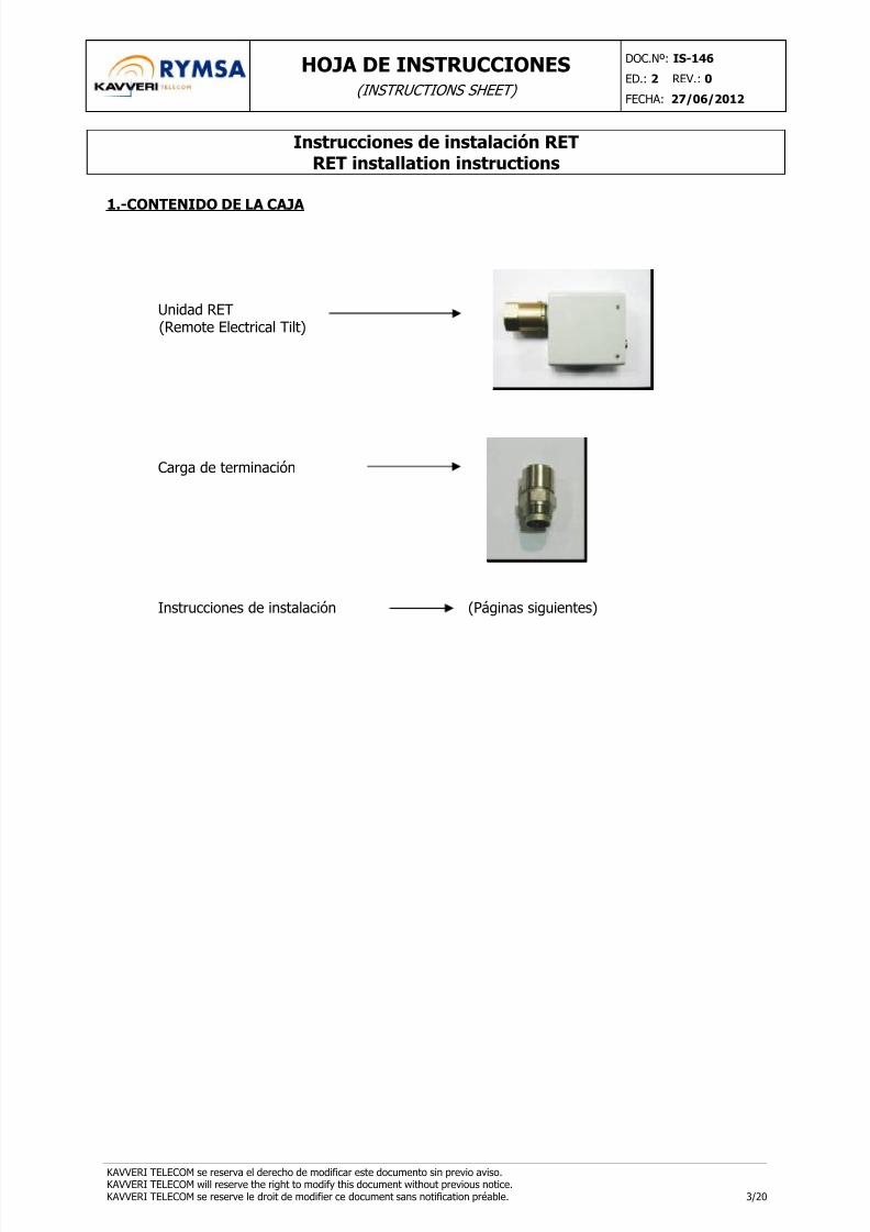
1.-CONTENIDO DE LA CAJA
Unidad RET(Remote Electrical Tilt)
Carga de terminación
Instrucciones de instalación (Páginas siguientes)

8/12/2019 RET Installation Instructions
http://slidepdf.com/reader/full/ret-installation-instructions 4/20
HOJA DE INSTRUCCIONES(INSTRUCTIONS SHEET)
DOC.Nº: IS-146
ED.: 2 REV.: 0
FECHA: 27/06/2012
Instrucciones de instalación RETRET installation instructions
KAVVERI TELECOM se reserva el derecho de modificar este documento sin previo aviso.KAVVERI TELECOM will reserve the right to modify this document without previous notice.KAVVERI TELECOM se reserve le droit de modifier ce document sans notification préable. 4/20
2.-IDENTIFICACIÓN DEL INTERFAZ MECÁNICO DE LA ANTENA PREPARADO PARA LACONEXIÓN DEL RET.
Localización del interfaz en la antena:
DESCRIPCIÓN GENERAL DE LA INTERFAZ (Sin protector):
1- Barra indicadora del tilt, con escala visual.2- Rueda de ajuste de tilt.3- Rosca guiada de fijación a la antena, tanto para el protector como para el RET.

8/12/2019 RET Installation Instructions
http://slidepdf.com/reader/full/ret-installation-instructions 5/20
HOJA DE INSTRUCCIONES(INSTRUCTIONS SHEET)
DOC.Nº: IS-146
ED.: 2 REV.: 0
FECHA: 27/06/2012
Instrucciones de instalación RETRET installation instructions
KAVVERI TELECOM se reserva el derecho de modificar este documento sin previo aviso.KAVVERI TELECOM will reserve the right to modify this document without previous notice.KAVVERI TELECOM se reserve le droit de modifier ce document sans notification préable. 5/20
3.-CONEXIÓN DEL RET
3.1.-Retirar la funda protectora del mecanismo de ajuste de tilt.
3.2.- Conectar el RET a la antena
Girar la rueda de ajuste de tilt hasta que queden visibles unos 30 mm de la varilla.
Colocar el RET sobre el eje de forma que quede en línea con la rosca de la antena.

8/12/2019 RET Installation Instructions
http://slidepdf.com/reader/full/ret-installation-instructions 6/20
HOJA DE INSTRUCCIONES(INSTRUCTIONS SHEET)
DOC.Nº: IS-146
ED.: 2 REV.: 0
FECHA: 27/06/2012
Instrucciones de instalación RETRET installation instructions
KAVVERI TELECOM se reserva el derecho de modificar este documento sin previo aviso.KAVVERI TELECOM will reserve the right to modify this document without previous notice.KAVVERI TELECOM se reserve le droit de modifier ce document sans notification préable. 6/20
El eje cuadrado del RET debe encajar en la cavidad de la rueda del mecanismo de ajuste de tilt dela antena. Además hay que hacer coincidir las tres muescas interiores del RET con las tres ranurasde la rosca de la antena.
Nota: Empujar el RET con cuidado hasta que se note que la junta hace tope con larosca.
Si el RET no ajusta perfectamente en el mando de la antena, gírelo levemente hasta que el eje y lacavidad cuadrados encajen. Cuando el eje y la cavidad estén bien acoplados, gire de nuevo el REThasta conseguir que coincidan las muescas del RET con las ranuras de la rosca de la antena.
Apretar la tuerca de fijación del RET. Se puede usar una llave dinamométrica de 40mm de anchuracon un torque máximo de 20 Nm, o bien se puede apretar con la mano.
1
3
2
Ranuras
Muescas
Eje y huecocuadrados

8/12/2019 RET Installation Instructions
http://slidepdf.com/reader/full/ret-installation-instructions 7/20
HOJA DE INSTRUCCIONES(INSTRUCTIONS SHEET)
DOC.Nº: IS-146
ED.: 2 REV.: 0
FECHA: 27/06/2012
Instrucciones de instalación RETRET installation instructions
KAVVERI TELECOM se reserva el derecho de modificar este documento sin previo aviso.KAVVERI TELECOM will reserve the right to modify this document without previous notice.KAVVERI TELECOM se reserve le droit de modifier ce document sans notification préable. 7/20
Una vez terminada la instalación, el RET debe quedar en la posición que se indica en la etiquetaque lleva adherida. A continuación se muestran algunos ejemplos de cómo debe quedar colocado:
Ejemplo 1:
Ejemplo 2:
ATENCION: Cualquier otra colocación puede dar problemas de funcionamiento y llegara deteriorar el RET.

8/12/2019 RET Installation Instructions
http://slidepdf.com/reader/full/ret-installation-instructions 8/20
HOJA DE INSTRUCCIONES(INSTRUCTIONS SHEET)
DOC.Nº: IS-146
ED.: 2 REV.: 0
FECHA: 27/06/2012
Instrucciones de instalación RETRET installation instructions
KAVVERI TELECOM se reserva el derecho de modificar este documento sin previo aviso.KAVVERI TELECOM will reserve the right to modify this document without previous notice.KAVVERI TELECOM se reserve le droit de modifier ce document sans notification préable. 8/20
3.3.-Cable de comunicación y carga de terminación
En el conector macho del RET se introducirá el cable de comunicación, que debe enroscarse paraque no se desprenda. Se hará manualmente, es importante no utilizar ningún tipo de llave, ya queel conector del RET podría dañarse por un par de apriete excesivo.
Si el conector hembra del RET no se va a conectar a otro cable de la cadena de comunicación,debe llevar colocada la carga de terminación.
Conector hembra Carga de terminación
3.4.-Conexión de RET en Daisy Chain
En el caso de que se utilice una configuración encadenada (Daisy Chain ) para conectar varios RETs, lacarga debe conectarse en la última salida que no esté conectada a un cable de control
8/12/2019 RET Installation Instructions
http://slidepdf.com/reader/full/ret-installation-instructions 9/20
HOJA DE INSTRUCCIONES(INSTRUCTIONS SHEET)
DOC.Nº: IS-146
ED.: 2 REV.: 0
FECHA: 27/06/2012
Instrucciones de instalación RETRET installation instructions
KAVVERI TELECOM se reserva el derecho de modificar este documento sin previo aviso.KAVVERI TELECOM will reserve the right to modify this document without previous notice.KAVVERI TELECOM se reserve le droit de modifier ce document sans notification préable. 9/20
4.-COMIENZO DE FUNCIONAMIENTO
4.1.- Configuración antena
El RET está preconfigurado para el modelo de antena que se indica en la etiqueta. Por tanto, estálisto para ser utilizado en ese tipo de antenas. Si se conecta la unidad en un modelo diferente, seránecesario cargar el software adecuado en el RET antes de su utilización; esta operación debe serefectuada en KAVVERI
4.2.-Calibración
La siguiente etapa es la calibración. Con este proceso el RET toma las referencias necesarias del
mecanismo de la antena para que cualquier movimiento posterior tenga la precisión adecuada
ATENCIÓN:
• Asegúrese de que la configuración del RET es la correcta para el modelo de antenaen que se va a utilizar antes de proceder a la calibración.
• Cada vez que un RET se desmonta de una antena y se vuelve a instalar necesita serre-calibrado mediante la SCU o Controlador Software, antes de realizar cualquieroperación con el dispositivo, (por ejemplo, programar un valor de tilt). Lacalibración inicial hay que realizarla incluso aunque el RET indique que ya estácalibrado.
• Cualquier movimiento de tilt sin haber calibrado antes o sin tener la configuración
correcta grabada en el RET puede dañar las unidades.
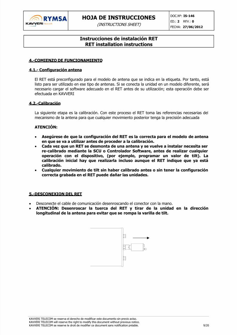
5.-DESCONEXION DEL RET
• Desconecte el cable de comunicación desenroscando el conector con la mano.• ATENCIÓN: Desenroscar la tuerca del RET y tirar de la unidad en la dirección
longitudinal de la antena para evitar que se rompa la varilla de tilt.

8/12/2019 RET Installation Instructions
http://slidepdf.com/reader/full/ret-installation-instructions 10/20
HOJA DE INSTRUCCIONES(INSTRUCTIONS SHEET)
DOC.Nº: IS-146
ED.: 2 REV.: 0
FECHA: 27/06/2012
Instrucciones de instalación RETRET installation instructions
KAVVERI TELECOM se reserva el derecho de modificar este documento sin previo aviso.KAVVERI TELECOM will reserve the right to modify this document without previous notice.KAVVERI TELECOM se reserve le droit de modifier ce document sans notification préable. 10/20
6.-ACTUACIÓN EN CASO DE FALLO
En caso de detectarse alguna anomalía en el funcionamiento del RET se deben revisar los siguientespuntos para detectar cualquier posible defecto de instalación y poderlo solucionar rápidamente.
(Ver instrucciones de desconexión del RET en el apartado 5).
¿El RET está correctamente instalado?
La posición correcta del RET se muestra en la etiqueta adherida en cada unidad. Ver detalles enpunto 3.2.
Además, la junta tórica debe estar totalmente pegada al interfaz de la antena.
SOLUCIÓN. Si la colocación del RET no es la adecuada, hay que desconectarlo, colocarlo denuevo de forma correcta y volver a calibrarlo (ver apdo. 4.1).
¿Hay comunicación con el RET?
Si se viera que no hay comunicación con el RET desde la estación de control en primer lugar sedebe revisar la conexión del mismo a los cables de comunicación, tal y como se explica en elsiguiente apartado.Si los cables están correctamente colocados, pero aún así, no hay comunicación con el dispositivose deberá sustituir el cable de conexión por uno nuevo para descartar que esté dañado.
¿Está correctamente conectado el cable de comunicación?
Los dos conectores del RET deben estar conectados bien al cable de comunicación o bien a unacarga de terminación, según se muestra en las siguientes imágenes. Para comprobar que laconexión es correcta y que el cable no está suelto se puede tirar ligeramente del cable. Si se sueltaes que el conector no estaba correctamente colocado o la tuerca del mismo no había quedadoenganchada a la rosca del conector del RET.

8/12/2019 RET Installation Instructions
http://slidepdf.com/reader/full/ret-installation-instructions 11/20
HOJA DE INSTRUCCIONES(INSTRUCTIONS SHEET)
DOC.Nº: IS-146
ED.: 2 REV.: 0
FECHA: 27/06/2012
Instrucciones de instalación RETRET installation instructions
KAVVERI TELECOM se reserva el derecho de modificar este documento sin previo aviso.KAVVERI TELECOM will reserve the right to modify this document without previous notice.KAVVERI TELECOM se reserve le droit de modifier ce document sans notification préable. 11/20
SOLUCIÓN. Retirar el cable y volver a colocarlo asegurándose de que la conexión de los pines escorrecta y que la tuerca queda completamente apretada. Se recuerda no utilizar ningún tipo dellave para asegurar el apriete del conector.
“No Calibrated Error”
Este error puede aparecer en el RET porque se haya perdido la posición de referencia almacenadaen el RET o bien porque se haya cambiado el fichero de configuración de la antena.
SOLUCIÓN. Si en el programa de control del RET aparece este error se deberá ordenar lacalibración. Si el problema persiste habrá que verificar que la colocación del RET es correcta segúnlos puntos anteriores.
“JAM Error”
Este error puede aparecer en el RET porque se haya producido algún atasco en el mecanismo demovimiento. Puede ser un error puntual o reiterado.
SOLUCIÓN. En primer lugar se debe intentar repetir la operación que se estaba tratando de llevara cabo. Si en la segunda ejecución del comando no hay dificultades, simplemente se trata de unaviso puntual. Pero, si el error persiste el RET entrará en modo “No Calibrated” y para solucionarlodebemos proceder tal y como se explica en el punto anterior.

8/12/2019 RET Installation Instructions
http://slidepdf.com/reader/full/ret-installation-instructions 12/20
HOJA DE INSTRUCCIONES(INSTRUCTIONS SHEET)
DOC.Nº: IS-146
ED.: 2 REV.: 0
FECHA: 27/06/2012
Instrucciones de instalación RETRET installation instructions
KAVVERI TELECOM se reserva el derecho de modificar este documento sin previo aviso.KAVVERI TELECOM will reserve the right to modify this document without previous notice.KAVVERI TELECOM se reserve le droit de modifier ce document sans notification préable. 12/20
1.-BOX CONTENT
RET Unit(Remote Electrical Tilt)
Termination load
Installation instructions (Next pages)

8/12/2019 RET Installation Instructions
http://slidepdf.com/reader/full/ret-installation-instructions 13/20
HOJA DE INSTRUCCIONES(INSTRUCTIONS SHEET)
DOC.Nº: IS-146
ED.: 2 REV.: 0
FECHA: 27/06/2012
Instrucciones de instalación RETRET installation instructions
KAVVERI TELECOM se reserva el derecho de modificar este documento sin previo aviso.KAVVERI TELECOM will reserve the right to modify this document without previous notice.KAVVERI TELECOM se reserve le droit de modifier ce document sans notification préable. 13/20
2.-IDENTIFICATION OF THE MECHANICAL INTERFACE OF THE ANTENNA PREPARED FORRET ATTACHMENT.
Location of the interface in a typical antenna:
GENERAL DESCRIPTION OF THE INTERFACE (Protective Cap removed):
1- Down tilt indicator bar with visual scale.2- Tilt Adjustment Knob.3- Guided thread to fix the protective cap, or the RET to the antenna
8/12/2019 RET Installation Instructions
http://slidepdf.com/reader/full/ret-installation-instructions 14/20
HOJA DE INSTRUCCIONES(INSTRUCTIONS SHEET)
DOC.Nº: IS-146
ED.: 2 REV.: 0
FECHA: 27/06/2012
Instrucciones de instalación RETRET installation instructions
KAVVERI TELECOM se reserva el derecho de modificar este documento sin previo aviso.KAVVERI TELECOM will reserve the right to modify this document without previous notice.KAVVERI TELECOM se reserve le droit de modifier ce document sans notification préable. 14/20
3.-RET CONNECTION
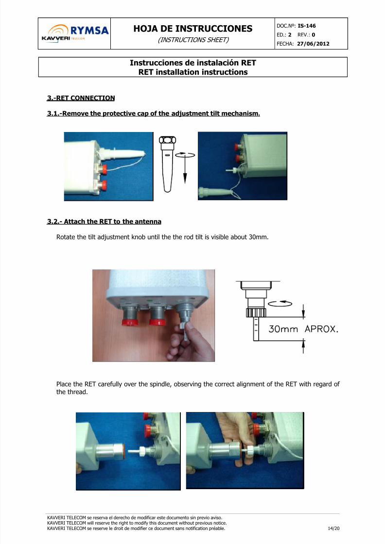
3.1.-Remove the protective cap of the adjustment tilt mechanism.
3.2.- Attach the RET to the antenna
Rotate the tilt adjustment knob until the the rod tilt is visible about 30mm.
Place the RET carefully over the spindle, observing the correct alignment of the RET with regard ofthe thread.

8/12/2019 RET Installation Instructions
http://slidepdf.com/reader/full/ret-installation-instructions 15/20
HOJA DE INSTRUCCIONES(INSTRUCTIONS SHEET)
DOC.Nº: IS-146
ED.: 2 REV.: 0
FECHA: 27/06/2012
Instrucciones de instalación RETRET installation instructions
KAVVERI TELECOM se reserva el derecho de modificar este documento sin previo aviso.KAVVERI TELECOM will reserve the right to modify this document without previous notice.KAVVERI TELECOM se reserve le droit de modifier ce document sans notification préable. 15/20
The square spindle of the RET must be fitted into the square cavity of the antenna tilt adjustmentknob. Also, you have to pay attention to match the three slots inside the RET with the threenotches of the antenna thread.
Note: Push-up the RET carefully until you notice the joint touches the thread.
If the RET does not fit perfectly into the mounting hub on the first attempt, rotate the RET slightlyuntil the square gear inside the RET lines up with the square cavity in the antenna knob, and pressuntil they are fitted together. Once this drive mechanism is properly engaged, rotate the RET backto the correct alignment with the three slots in the mounting hub.
Tighten the RET attachment nut. You can use a torque-wrench with 40 mm in width, and amaximum torque of 20 Nm, or you can tighten by hand.
1
3
2
Notches
Slots
Square spindleand cavity

8/12/2019 RET Installation Instructions
http://slidepdf.com/reader/full/ret-installation-instructions 16/20
HOJA DE INSTRUCCIONES(INSTRUCTIONS SHEET)
DOC.Nº: IS-146
ED.: 2 REV.: 0
FECHA: 27/06/2012
Instrucciones de instalación RETRET installation instructions
KAVVERI TELECOM se reserva el derecho de modificar este documento sin previo aviso.KAVVERI TELECOM will reserve the right to modify this document without previous notice.KAVVERI TELECOM se reserve le droit de modifier ce document sans notification préable. 16/20
When installation is finished the RET must be placed as shown in the label stuck on the unit.Some examples are shown below:
Example 1:
Example 2:
CAUTION: Another collocation could produce problems and even deteriorate thedevice.

8/12/2019 RET Installation Instructions
http://slidepdf.com/reader/full/ret-installation-instructions 17/20
HOJA DE INSTRUCCIONES(INSTRUCTIONS SHEET)
DOC.Nº: IS-146
ED.: 2 REV.: 0
FECHA: 27/06/2012
Instrucciones de instalación RETRET installation instructions
KAVVERI TELECOM se reserva el derecho de modificar este documento sin previo aviso.KAVVERI TELECOM will reserve the right to modify this document without previous notice.KAVVERI TELECOM se reserve le droit de modifier ce document sans notification préable. 17/20
3.3.-Communication cable and termination load
The communication cable should be connected to the male connector of the RET. It has to bethreaded by hand to fix it. Do not use any tool to tighten the connector so that it is not damaged.
Termination load shall be connected on the female connector when this is not used for a cable.
Female connector Termination load
3.4.- Daisy Chain RET connection
If you have to use Daisy Chain configuration to connect multiple RETs, termination load must be fixedto the last output not connected to a control cable
8/12/2019 RET Installation Instructions
http://slidepdf.com/reader/full/ret-installation-instructions 18/20
HOJA DE INSTRUCCIONES(INSTRUCTIONS SHEET)
DOC.Nº: IS-146
ED.: 2 REV.: 0
FECHA: 27/06/2012
Instrucciones de instalación RETRET installation instructions
KAVVERI TELECOM se reserva el derecho de modificar este documento sin previo aviso.KAVVERI TELECOM will reserve the right to modify this document without previous notice.KAVVERI TELECOM se reserve le droit de modifier ce document sans notification préable. 18/20
4.-STARTING OPERATION
4.1.- Antenna Configuration
The RET is pre-configured for the antenna model which is indicated on the label. Therefore, it willbe ready to use with this type of antenna. If the unit is mounted in a different antenna model, itwill be necessary to download the right software; this operation should be performed in KAVVERI.
4.2.-Calibration
Next step will be calibration. During this process the RET captures the external necessaryreferences of the antenna mechanism in order to perform next movements with the pertinent
precision.
CAUTIONS:
• Please, be sure that the RET unit has the right configuration for the antenna modelin which it will be connected before calibration.
• Anytime a RET is released and attached again to an antenna it is necessary toperform a calibration procedure using the SCU or Software controller, beforeexecuting any operation with the RET (e.g., programming any tilt). The initialcalibration procedure is necessary even though the RET indicate that it is alreadycalibrated.
• Any tilt operation without a previous calibration or using a wrong configuration
could damage the units.
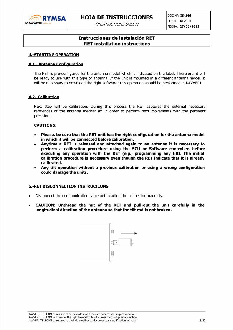
5.-RET DISCONNECTION INSTRUCTIONS
• Disconnect the communication cable unthreading the connector manually.
• CAUTION: Unthread the nut of the RET and pull-out the unit carefully in thelongitudinal direction of the antenna so that the tilt rod is not broken.

8/12/2019 RET Installation Instructions
http://slidepdf.com/reader/full/ret-installation-instructions 19/20
HOJA DE INSTRUCCIONES(INSTRUCTIONS SHEET)
DOC.Nº: IS-146
ED.: 2 REV.: 0
FECHA: 27/06/2012
Instrucciones de instalación RETRET installation instructions
KAVVERI TELECOM se reserva el derecho de modificar este documento sin previo aviso.KAVVERI TELECOM will reserve the right to modify this document without previous notice.KAVVERI TELECOM se reserve le droit de modifier ce document sans notification préable. 19/20
6.-ACTION IN CASE OF FAIL
Here it is presented a guide of some cases where the RET could fail in order to check when itbehaves in an anomalous way. Also, it is shown how you should act to solve the problem.
(For RET disconnection refer to part 5).
¿RET is perfectly installed?
Remember the right position of the RET to be correctly installed is as shown on the label stuck onthe unit. See paragraph 3.2 for details.
Also, it is very important that the RET’s joint fit perfectly with the antenna thread.
SOLUTION. If the position of the RET is not exactly as described above, better disconnect theunit and try to mount correctly. After this, the RET should be calibrated again.
¿Communication is right?
In cases that communication with RET appears to be lost, first step will be checking the completeconnection way. Revise all the cables and their connections to the RET and the controller station. Ifconnections are well fitted but still there are communication problems, next step will be changingthe cable by a new one to verify it is not damaged.
How to know if the communication cable is right connected
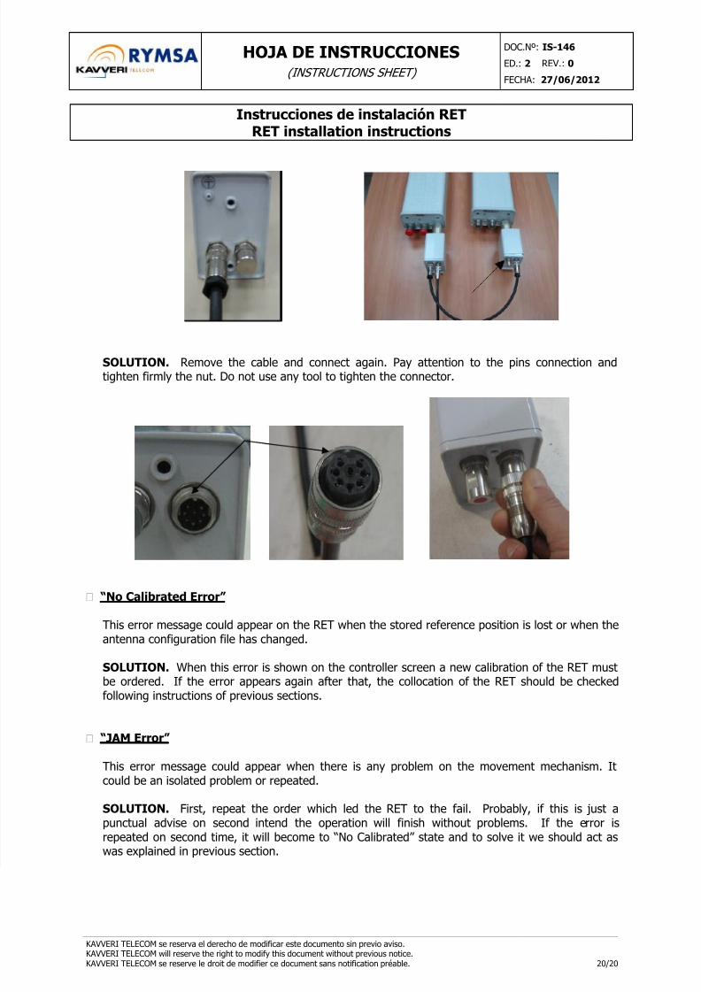
Both RET connectors should be connected one, at least, to a communications cable and the otherto a termination load, as you can see on next pictures. To check if the connection is right fitted youcan pull softly of it. If the connector is not right connected the communication cable will release.
8/12/2019 RET Installation Instructions
http://slidepdf.com/reader/full/ret-installation-instructions 20/20
HOJA DE INSTRUCCIONES(INSTRUCTIONS SHEET)
DOC.Nº: IS-146
ED.: 2 REV.: 0
FECHA: 27/06/2012
Instrucciones de instalación RETRET installation instructions
SOLUTION. Remove the cable and connect again. Pay attention to the pins connection andtighten firmly the nut. Do not use any tool to tighten the connector.
“No Calibrated Error”
This error message could appear on the RET when the stored reference position is lost or when theantenna configuration file has changed.
SOLUTION. When this error is shown on the controller screen a new calibration of the RET mustbe ordered. If the error appears again after that, the collocation of the RET should be checked
following instructions of previous sections.
“JAM Error”
This error message could appear when there is any problem on the movement mechanism. Itcould be an isolated problem or repeated.
SOLUTION. First, repeat the order which led the RET to the fail. Probably, if this is just apunctual advise on second intend the operation will finish without problems. If the error isrepeated on second time, it will become to “No Calibrated” state and to solve it we should act aswas explained in previous section.