resistance spot welding of steel sheets … · resistance spot welding of steel sheets of the same...
TRANSCRIPT
807
ACTA UNIVERSITATIS AGRICULTURAE ET SILVICULTURAE MENDELIANAE BRUNENSIS
Volume 65 83 Number 3, 2017
https://doi.org/10.11118/actaun201765030807
RESISTANCE SPOT WELDING OF STEEL SHEETS OF THE SAME AND DIFFERENT THICKNESS
Milan Brožek1, Alexandra Nováková1, Ota Niedermeier2
1 Department of Material Science and Manufacturing Technology, Faculty of Engineering, Czech University of Life Sciences Prague, Kamýcká 129, 165 21 Praha 6 – Suchdol, Czech Republic
2 AŽD Praha, spol. s r. o., Žirovnická 2, 106 00 Praha 10 – Záběhlice, Czech Republic
Abstract
BROŽEK MILAN, NOVÁKOVÁ ALEXANDRA, NIEDERMEIER OTA. 2017. Resistance Spot Welding of Steel Sheets of the Same and Different Thickness. Acta Universitatis Agriculturae et Silviculturae Mendelianae Brunensis, 65(3): 807–814.
Resistance welding ranks among progressive and in practice often used manufacturing techniques of rigid joints. It is applied in single‑part production, short‑run production as well as in mass production. The basis of this method is in the utilization of the Joulean heat, which arises at the passage of current through connected sheets at collective influence of compressive force. The aim of the carried out tests was the determination of the dependence between the rupture force of spot welds made using steel sheets of the same and different thickness for different welding conditions. For carrying out of this aim 360 assemblies were prepared. The sheets (a total of 720 pieces) of dimensions 100 × 25 mm and thickness of 0.8 mm, 1.5 mm and 3.0 mm were made from low carbon steel. In the place determined for welding the test specimens were garnet blasted and then degreased with acetone. The welding of two specimens always of the same (0.8+0.8 mm, 1.5+1.5 mm a 3.0+3.0 mm) and different (0.8 + 1.5 mm, 0.8+3.0 mm a 1.5+3.0 mm) thickness was carried out using the welding machine type BV 2,5.21. At this type the welding current value is constant (Imax = 6.4 kA). The welding time (the time of the passage of the current) was changed in the whole entirety, namely 0.10 s, 0.15 s, 0.20 s, 0.25 s, 0.3 s, 0.4 s, 0.6 s, 0.8 s, 1.0 s, 1.3 s, 1.6 s and 2.0 s. The compressive force was chosen according to the thickness of the connected sheets in the range from 0.8 to 2.4 kN. From the results of carried out tests it follows that using the working variables recommended by the producer we obtain the quality welds. But it we use the longer welding times, we can obtain stronger welds, namely up to 21 % compared to welds made using working variables recommended by the producer.
Keywords: Resistance welding; steel sheet; laboratory test; shear testing resistance spot welds
INTRODUCTIONJoints of two or more parts used in practice are
usually divided into removable and rigid ones. Removable joints, made e.g. using screws, washers and nuts, we can repeatedly dismantle and assemble without damage of above mentioned parts. On the contrary, rigid joints are permanent. They can be “dismantled” (affect of strength or heat), but at the cost of their irreversible damage (destruction). It is a case of joints made by riveting (Brožek and Nováková, 1995), adhesive bonding of metallic and non‑metallic materials (Brockmann et al., 2009; Brožek, 2014b; Brožek, 2013a; Brožek, 2013d), soldering (Brožek, 2013b; 2013c; Nippes, 1983;
Ruža, 1988) or welding and overlaying (Blaščík et al., 1987; Brožek, 2012; 2011).
A row of welding methods exists today – they are classified according to ČSN EN ISO 4063. One of them is resistance welding (resistance welding, method 2). In the world the resistance welding is known already since eighteen eighties. But in our country it begins to be used since nineteen thirties. Since then the technology has been very advanced. Today spot welding is used not only for welding of ferrous steels including stainless steels (Liu et al., 2011; 2013; Peasura, 2011; Pouranvari, 2011), but also of non‑ferrous metals (Field and Sutton, 1941; Kramár, 2015). It is possible to weld sheets with previous surface finish, e.g. zinc‑coated

808 Milan Brožek, Alexandra Nováková, Ota Niedermeier
sheets (Hayat and Sevim, 2012; Svítil, 1980; Wang et al., 2013). Without problems it is today possible to weld two different materials, too (Kaščák, 2014; Kolařík, 2012). The most typical application of resistance welding technology is today in car industry (Hipperson and Watson, 1950; Hipperson, 1952; Hayat and Sevim, 2012). Modern technologies make possible the on‑line quality monitoring and controlling of resistance spot welding (Li, 2012). It is paid attention to the spot welds behavior under conditions of fatigue (Younger et al., 1966).
According to ČSN EN ISO 4063 the resistance welding falls into spot welding (resistance spot welding, method 21) and seam welding (resistance seam welding, method 22). At the spot welding, which is studied in this contribution, the weld is created in the contact of welded materials (sheets) between surfaces of two electrodes. The area of the weld (so called nugget or button) is approximately the same as the area of the ends of the electrodes (Hipperon and Watson, 1950; Holásek, 1968; Zhang and Senkara, 2012).
At the resistance welding (Welding Committee, 1956; Li, 2012; Brožek, 2014a; 2015; 2016) the collective influence of Joulean heat (1), arising by passage of current through the welded materials, and compressive force, is used.
Q = R.I2.t (1)
WhereQ ... Heat (J),R .... Resistance (Ω),I ..... Welding current (A)t ..... Welding time (s).
The heat Q, which is needed to the melting‑down of the required metal volume, can be achieved by two ways. Depending on this we distinguish the short time welding conditions (high I, short t) and the long time welding conditions (low I, long t). The final quality of spot welds depends on the optimum setting of the working variables by the operator, primarily on the welding current intensity, on the time of the current passage and on the compressive force.
MATERIALS AND METHODSSize, dimensions and shear testing procedure
of spot welds for sheets of thickness from 0.5 mm to 10.0 mm are stated in the standard ČSN EN ISO 14273. The size of test specimens is different depending on the welded sheets thickness. The width ranges from 45 mm to 100 mm, exceptionally from 30 mm to 100 mm. The length ranges from 175 mm to 320 mm. The lapping length ranges from 35 to 100 mm. Therefore the dimensions of the specimens were unified. They
1: Dimensions and shape of test specimens
2: Macrostructure of spot weld, sheet thickness 1.5 + 1.5 mm, t = 2.0 s
Resistance Spot Welding of Steel Sheets of the Same and Different Thickness 809
were used the dimensions of test specimens used in our department already over a long period for tests of adhesive bonded joints, soldered joints or riveted joints.
The test specimens for spot welding were made from the low‑carbon steel 11 321.21 according ČSN 41 1321 (steel DC01 according EN, steel St1203 according DIN). Sheets of size 1000 × 2000 mm and thickness 0.8 mm, 1.5 mm and 3.0 mm were the semi‑products for their production. The parting of semi‑products to test specimens was carried out by shearing. The dimensions and shape of the test specimens and the location of the spot weld (nugget) is evident from Fig. 1 (L = 100 mm, b = 25 mm, l = 25 mm). Illustration of macrostructure of spot weld is shown in Fig. 2.
The surface preparation of the test specimens before the spot welding is very important. All potential dirt on the material surface decreases the joint strength, or makes impossible the spot weld formation. Therefore the surface of all specimens was blasted under the angle 90° using artificial garnet (fraction MESH 80, abrasive grain size 0.1 to 0.3 mm) on one end (determined for welding) on both sides during 30 mm. After blasting all specimens were degreased using acetone and dried using warm air. Immediately the spot welding ensued.
The surface roughness of sheets before and after blasting was measured (according to ČSN EN ISO 4287) with apparatus for measuring roughness Surftest SJ‑301. In doing so, there were checked two parameters, Ra (arithmetical mean deviation of the assessed profile, μm) and Rz (maximum height of profile, μm). In each of the six series of samples the measurement was repeated ten times in the direction of the longer dimension of the sample, and ten times in the direction of the shorter dimension of the sample. It was performed in total of 240 measurements. A very good repeatability of surface preparation was proved by evaluation; determined roughness values between each series of samples differed only minimally. Sheet roughness (Ra) before adjustment was 0.91 ± 0.14 μm, Rz was 6.6 ± 1.1 μm. Sheet roughness Ra after treatment was 2.56 ± 0.33 μm, Rz was 21.3 ± 3.7 μm.
For welding of the assembly consisting from two specimens of the same and different thickness the spot welder type BV 2,5.21 was used. The welder uses the long time welding conditions. It is determined only for shops with piece production and so for the lower work intensity, e.g. for school
and remedial workshops and fitting shops. The reason is the highest permissible current and heat load of electrodes, which are cooled only by air.
The producer recommends the welder for welding of steel sheets from low‑carbon steel till to Cmax = 0.3 % and 2.5 + 2.5 mm thickness. Owing to study reasons the spot welds of sheets 3.0 + 3.0 mm were carried out, too.
The main parts of the spot welder are the welding transformer type T 2,5.12, the lever weighting and the electronic device type QX 12.1. The electronics ensures the reproducible setting of the chosen selected variables and the compensation of possible changes of the supply voltage. The required compressive force is set by means of the spring by turn of the setting nut. The welding time (time of the current passage) is possible to set in 12 steps from 0.1 to 2.0 s. According to the producer instruction it is possible to make only limited number joints within a hour, which depends on the welded sheets thickness (Tab. I). At this welder the welding time t and the compressive force F (Tab. I) are the basic parameters, which is possible to set. The welding current cannot be changed (Imax = 6.4 kA).
For the purpose of the experiment always the couple of specimens (assembly) of the same thickness was spot welded, so 0.8 + 0.8 mm, 1.5 + 1.5 mm and 3.0 + 3.0 mm and also of the different thickness, so 0.8 + 1.5 mm, 0.8 + 3.0 mm a 1.5 + 3.0 mm. For each sheet thickness the making of 5 assemblies was proposed, always at the use of all 12 welding times (0.10 s, 0.15 s, 0.20 s., 0.25 s, 0.3 s, 0.4 s, 0.6 s, 0.8 s, 1.0 s, 1.3 s, 1.6 s, and 2.0 s). 355 usable assemblies were made, 5 assemblies failed to be welded. It is the case of sheet of 3.0 mm thickness at the shortest welding time 0.10 s. After welding all assemblies were loaded using the universal test machine LabTest 5.50 ST till to their rupture. Speed of loading of the welded assemblies was 10 mm·min−1. The spot weld rupture was characterized by the destruction in the spot weld (nugget) or in the sheet.
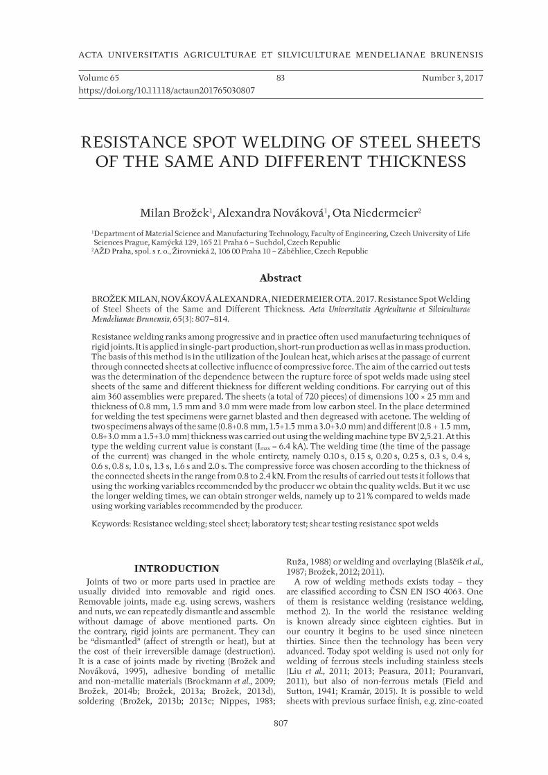
I: Welding variables
Sheet thickness, mm Welding time, s Compressive force, kN Orientation welding speed, spot·h−1
0.8 + 0.8 0.15 0.8 180
1.5 + 1.5 0.6 1.5 56
3.0 + 3.0 1.6 2.4 26
Note: Variables for the sheet thickness 3.0 + 3.0 were recalculated.

810 Milan Brožek, Alexandra Nováková, Ota Niedermeier
3: Destruction in the spot weld (nugget), sheet thickness 3.0 + 3.0 mm, t = 0.6 s
4: Destruction in the sheet, sheet thickness 1.5 + 3.0 mm, t = 0.6 s
Resistance Spot Welding of Steel Sheets of the Same and Different Thickness 811
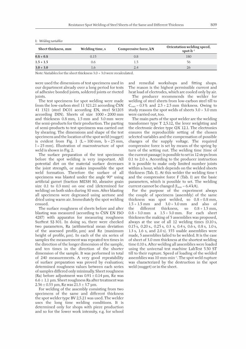
RESULTS AND DISCUSSIONThe results of the carried out tests are shown in
Fig. 5 and Fig. 6. At all measured values the standard deviation is demonstrated by the line segments.
In Fig. 5 there are the results obtained on samples made from sheets of equal thickness. For sheets of thickness 0.8 + 0.8 mm at increasing welding time there was a slight increase in strength (up to t = 0.4 s). With further increasing time of passage of current the strength of the joints practically did not change. Explanation of causes can be found in the mode of failure of the spot weld. While for shorter periods of welding there was always the destruction of the spot weld, for longer periods of passage of the welding current there is always a breach of the welded material. More significant change of the strength of spot welds occurred in sheets of thickness 1.5 + 1.5 mm. When the welding time was increased there was practically linear increase in resistance of spot connections (to t = 0.8 s). With further increasing time of passage of current,
however, the trend changed and the bearing point of the spot weld was practically constant. Explanation of cause is the same as in previous samples. Spot welds of sheets of thickness 3.0 + 3.0 mm could not be made at the lowest welding time (t = 0.1 s). With increasing time of passage of current (from t = 0.15 s), the strength of spot welds relatively sharply, almost linearly, increased up to the time the current passes t = 0.8 s. In a further lengthening the time of welding, the strength increased further, but less dramatically. The highest strength of spot welds were made during the longest time of passage of the current (t = 2.0), which used spot welder allows. Unlike the two previous groups of samples, in these samples the breach in the weld always occurred. The cause is probably the amount of heat supplied to the weld. This is especially for shorter times insufficient to create a quality spot weld. Possibility of welding these thicknesses is not declared by equipment manufacturer. It can
5: Relation between rupture force and time of passage of current (sheets of the same thickness), the standard deviation is demonstrated by the line segments
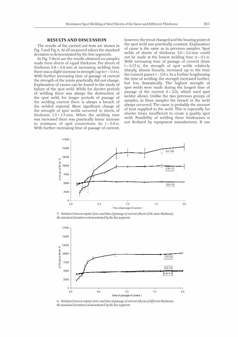
6: Relation between rupture force and time of passage of current (sheets of different thickness), the standard deviation is demonstrated by the line segments

812 Milan Brožek, Alexandra Nováková, Ota Niedermeier
be stated that the joints had considerable strength, especially at longer welding times (over t = 0.8 s).
In Fig. 6 there are the results obtained on samples made from sheets of different thicknesses. The test results of spot welds sheets of thickness 0.8 + 1.5 mm and 0.8 + 3.0 mm are very similar, almost identical. For lower welding time (up to t = 0.4 s) the strength of spot welds increased. For longer welding time (above t = 0.6 s) the joint strength further, but only very slightly, increased, and this increase was practically linear. For these two combinations of plate thicknesses occurred destruction of joints in welded material of less thickness during all welding times. Different results were obtained in spot weld sheets of thickness 1.5 + 3.0 mm. Bond strength increased rapidly until the passage of current t = 0.4 s. With the increase in the time of passage of current (up to t = 0.8 s) the strength of spot welds further increased, but less dramatically. When longer times of welding had been used, the strength of spot welds did not increase anymore. Explanation of cause is again to be found in evaluation of destruction of spot weld. Likewise the case with connections of sheets of the same thickness (0.8 mm and 1.5 mm), there are times when shorter welding always caused a violation of the spot weld and for longer periods of welding there is always a violation of material welded joints.
In comparison with data stated in Tab. I, Fig. 5 and Fig. 6 we find out that the spot welds, made
using the working variables recommended by the producer, do not reach the highest rupture force. The producer of the welder evidently has taken into consideration, although he has not stated it, the economical production of spot welds. The welds made using the working variables recommended by the producer are no doubt quality and in operation reliable. But when a customer using this welder will demand the highest joint rupture force, it is necessary to use the working variables recommended by the authors of the contribution and obtained on the basis of the carried out experiments. But he has to take into consideration that at the prolonged time of current passage the energy consumption increases and the production will cost more than expected. But by the prolonged passage of current it is possible to increase the spot weld rupture force at sheets of thickness 0.8 + 0.8 mm of about 11 %, at sheets of thickness 1.5 + 1.5 mm of about 21 %, at sheets of thickness 3.0 + 3.0 mm of about 4 %, at sheets of thickness 0.8 + 1.5 mm of about 18 %, at sheets of thickness 0.8 + 3.0 mm of about 7 % and at sheets of thickness 1.5 + 3.0 mm of about 3 % compared to welds made using the welding variables according to the producer. By the experiments it was further proved that using the spot welder type BV 2,5.21 it is possible to weld successful thicker sheets than it is stated, concretely of thickness 3.0 + 3.0 mm.
CONCLUSIONIn the contribution the rupture force results of the spot welds tests of the assemblies from two sheets of the same and different thickness are published. The spot welds were made using the spot welder BV 2,5.21. The test specimens of size 100 × 25 mm were made from the low‑carbon steel. In the place of the future weld the sheets were before welding on both sides garnet blasted and degreased with acetone. In total 355 assemblies were spot welded using different working variables. Following variables were changed: welded sheets thickness (0.8 + 0.8 mm, 1.5 + 1.5 mm, 3.0 + 3.0 mm, 0.8 + 1.5 mm, 0.8 + 3.0 mm and 1.5 + 3.0 mm) and time of current passage (0.10 s, 0.15 s, 0.20 s, 0.25 s, 0.3 s, 0.4 s, 0.6 s, 0.8 s, 1.0 s, 1.3 s, 1.6 s and 2.0 s); the welding current intensity was constant (Imax = 6.4 kA). The compressive force was chosen according to the welded sheets thickness from 0.8 to 2.4 kN.On the basis of the carried out tests it is possible to state:The spot weld rupture was characterized by the destruction in the spot weld (at shorter welding time) or in the sheet (at longer welding time),Using the working variables recommended by the producer (Tab. 1) we obtain always quality and in practice usable welds,If we use longer welding times we obtain welds of higher rupture force, namely of 3 to 21 % compared to by the producer recommended variables,The use of the longer welding time means however higher electric energy consumption and so higher costs; therefore this welding conditions are applicable only there, where it is explicitly demanded.

Resistance Spot Welding of Steel Sheets of the Same and Different Thickness 813
REFERENCESBLAŠČÍK, F. et al. 1987. Technology of Forming, Founding and Welding [In Slovak: Technológia tvárnenia, zlievárenstva
a zvárania]. Bratislava: ALFA.BROCKMANN, W. et al. 2009. Adhesive bonding: materials, applications and technology. Weinheim: Wiley‑VCH.BROŽEK, M. 2011. Layer number influence on weld deposit chemical composition. In: Engineering for Rural
Development. Latvia University of Agriculture, 26 – 27 May 2011. Jelgava: Latvia University of Agriculture, p. 393 – 397.
BROŽEK, M. 2013a. Technical‑economical evaluation of plywood bonding. In: Trends in Agricultural Engineering. Czech University of Life Sciences Prague, 3 – 6 September 2013. Prague: Czech University of Life Sciences Prague, 100 – 105.
BROŽEK, M. 2013b. Soldering steel sheets using soft solder. Research in Agriculture Engineering, 59(4): 141 – 146. BROŽEK, M. 2013c. Soldering sheets using soft solders. Acta Universitatis Agriculturae et Silviculturae Mendelianae
Brunensis, 61(6): 1597 – 1604.BROŽEK, M. 2013d. Optimization of adhesive layer thickness at metal bonding using quick‑setting
adhesives. Manufacturing Technology, 13 (4): 419 – 423.BROŽEK, M. 2014a. Working variables optimization of resistance spot welding. Manufacturing Technology,
14(4): 522 – 527.BROŽEK, M. 2014b. Technical‑economical evaluation of beech plywood bonding. In: Engineering for Rural
Development. Latvia University of Agriculture, 29 – 30 May 2014. Jelgava: Latvia University of Agriculture, p. 168 – 173.
BROŽEK, M. 2015. Resistance spot welding of steel sheets of different thickness. In: Engineering for Rural Development. Latvia University of Agriculture, 20 – 22 May 2015. Jelgava: Latvia University of Agriculture, p. 72 – 77.
BROŽEK, M. 2016. Resistance spot welding of steel sheets. Manufacturing Technology, 16(4): 662 – 666. BROŽEK, M. and NOVÁKOVÁ, A. 1995. Comparison of blind rivets of different producers. [In
Czech: Porovnání jednostranných nýtů s trnem různých výrobců]. In: XXXVI. konference kateder částí a mechanismů strojů (díl 1). VUT Brno, 13 – 14 June 1995. Brno: VUT, p. 37 – 40.
BROŽEK, M., 2012. Wear resistance of multi‑layer overlays. In: Engineering for Rural Development. Latvia University of Agriculture, 24 – 25 May 2012. Jelgava: Latvia University of Agriculture, p. 210 – 215.
FIELD, G. H. and SUTTON, H. 1941. The spot welding of light alloys. Aircraft Engineering and Aerospace Technology, 13(1): 17 – 26.
HAYAT, F. and SEVIM, I. 2012. The effect of welding parameters on fracture toughness of resistance spot‑welded galvanized DP600 automotive steel sheets. International Journal of Advanced Manufacturing Technology, 58(9 – 12): 1043 – 1050.
HIPPERSON, J. 1952. Scientific and mass production aspects of resistance welding. Journal of the Institution of Production Enginners, 31(8): 337 – 358.
HIPPERSON, J. and WATSON, T. 1950. Resistance welding in mass production. London: Illiffe & Sons. HOLÁSEK, J. 1968. Resistance welding [In Slovak: Odporové zváranie]. Bratislava: Slov. vydav. technické literatury.KAŠČÁK, L. and SPIŠÁK, E. 2014. Effect of welding parameters on the quality of spot welds combining
AHSS steel and HSLA steel. Key Engineering Materials, 586: 162 – 165. KOLAŘÍK, L., SAHUL, M., KOLAŘÍKOVÁ, M., SAHUL, M., TURŇA, M. and FELIX, M. 2012. Resistance
Spot Welding of Dissimilar Steels. Acta Polytechnica, 52(3): 43 – 47. KRAMÁR, T., VONDROUŠ, P., KOLAŘÍKOVÁ, M., KOVANDA, K., KOLAŘÍK, L. and ONDRUŠKA, M. 2015.
Resistance Spot Welding of Magnesium Alloy AZ91. MM Science Journal, 2015(March): 596 – 599.LI, R. X. 2012. Quality monitoring of resistance spot welding based on process parameters. Energy Procedia,
14: 925 – 930. LIU, H., WANG, H., ZHANG, X. and LI, C. 2011. Optimization of parameters and research on
joint microstructure of resistance spot welding of 201stainless steel. Advanced Materials Research, 418 – 420: 1359 – 1363.
LIU, H., XU, X. and ZHANG, X. 2013. Optimization of parameters and research on joint microstructure of resistance spot welding for 316 stainless steel. Advanced Materials Research, 652 – 654: 2326 – 2329.
NIPPES, E. F. 1983. Metals Handbook. Vol. 6., Welding, Brazing, and Soldering. Metal Park: ASM International.PEASURA, P., 2011. The influence of welding parameters on effected the complete for resistance spot
welding on mild steel. Advanced Materials Research, 214: 113 – 117.POURANVARI, M. 2011. Effect of resistance spot welding parameters on the HAZ softening of DP980
ferrite‑martensite dual phase steel welds. World Applied Sciences Journal, 15(10): 1454 – 1458.RUŽA, V. 1988. Soldering [In Czech: Pájení]. Praha: SNTL.SVÍTIL, A. 1980. Resistance spot welding of thin galvanized steel sheets [In Czech: Odporové bodové svařování tenkých
pozinkovaných ocelových plechů]. Praha: b. t. ÚNMZ 1987. Steel 11 321 [In Slovak: Oceľ 11 321]. ČSN 41 1321. Praha: Úřad pro technickou normalizaci,
metrologii a státní zkušebnictví.

814 Milan Brožek, Alexandra Nováková, Ota Niedermeier
ÚNMZ 1999. Geometrical product specifications (GPS) – Surface texture: Profile method – Terms, definitions and surface texture parameters [In Czech: Geometrické požadavky na výrobky (GPS) – Struktura povrchu: Profilová metoda – Termíny, definice a parametry struktury povrchu]. ČSN EN ISO 4287. Praha: Úřad pro technickou normalizaci, metrologii a státní zkušebnictví.
ÚNMZ 2003. Specimen dimensions and procedure for shear testing resistance spot, seam and embossed projection welds [In Czech: Rozměry vzorku a postup zkoušení střihem odporových bodových, švových a výstupkových svarů]. ČSN EN ISO 14273. Praha: Úřad pro technickou normalizaci, metrologii a státní zkušebnictví.
ÚNMZ 2010. Welding and allied processes – Nomenclature of processes and reference numbers [In Czech: Svařování a příbuzné procesy – Přehled metod a jejich číslování]. ČSN EN ISO 4063. Praha: Úřad pro technickou normalizaci, metrologii a státní zkušebnictví.
WANG, Z., WANG, Y. and ZHANG, D. 2013. Optimization on parameters of resistance spot welding process for galvanized steel plate. Advanced Materials Research, 658: 178 – 181.
WELDING COMMITTEE, AMERICAN WELDING SOC. 1956. Resistance welding: Theory and use. New York: Reinhold.
YOUNGER, A., GOURD, L. M. and JUBB, J. E. M. 1966. An Investigation into the Fatigue Properties of a Single Spot Weld Lap Joint. Cranfield: College of Aeronautics.
ZHANG, H. and SENKARA, J. 2012. Resistance Welding: Fundamentals and Applications. 2nd Edition. Boca Raton: CRC Press.
Contact information
Milan Brozek: [email protected]