reservedelenlijst parts list rc11 spare parts … · figures all parts shown in the figures bear an...
TRANSCRIPT
Wijzigingen voorbehouden
Subject to alterations
Änderungen vorbehalten
Toutes modifications reservées
Salvo modificaciones
RESERVEDELENLIJST •••• PARTS LIST RC11
SPARE PARTS COMPRESSOR &
ERSATZTEILEN ACCESSORIES
PIECES DE RECHANGE
PIEZAS DE RECAMBIO •••• PARTS LIST RC11
HISTORY
00.89.280 v002.00.01

Refrigeration Division
Grasso
v001.99.06 00.89.280

This booklet contains:1. the parts list RC11 of the compressor & accessories
2. the parts list RC11 of the history
IMPORTANT!!! HOW TO ORDER SPARE PARTS
When ordering spare parts, please always state:
TYPE
of the compressor, as shown on the type plate
SERIAL NO.
QUANTITY
DESCRIPTION of the required parts, as shown in the spare parts list
REF. NO.
Any incomplete specification may cause delay in delivery or shipment of the wrong parts:for cases like these no responsibility can be assumed.
Refrigeration Division
GrassoI N T R O D U C T I O N
V001.99.06.en

Refrigeration Division
GrassoI N T R O D U C T I O N
V001.99.06.en

Figures
All parts shown in the figures bear an item number. Assemblies are ndicated by a dotted frame with separate item number around the partsincluded in that particular assembly; the parts themselves bear the sameitem number, follow-ed by a sequence number (e.g. 2.1, 2.3, 2.3, etc.).
Parts lists
The parts are specified by the headings “Item”, “Description” “Ref. no.”and “Qty” (= Quantity). If an asterisk is used instead of the Ref. no., thismeans that the relevant part cannot be obtained separately.
When for some part no quantity has been given, the quantity requireddepends on the compressor size. When determining the required quantity
of parts, it should be considered that the listed quantities relate tothe corresponding figure and not to the compressor as a whole.When ordering, for example, valve rings for two discharge valves, thequantities stated in the relevant list must be doubled, because theseapply to one discharge valve only.If a compressor serial number is mentioned in the column "Remarks"behind one or more ref. nos., this means that the relevant part or subassembly has been mounted in all standard compressors bearingthis or a higher serial no. when leaving the factory.For the corresponding part or subassembly, not standard any more,applied in compressors with a lower serial no., the history parts listhas to be consulted, which is located behind the compressor parts list.
The standard illustrated parts list on the following pages is meant for identification and accurate specification of currentspare parts. Refer to the Monitron CR instruction manual, Chapter 8, Par. 8.7, if equipped with a Monitron CR-Control. Inorder to facilitate quick retrieval of the required parts, the list and corresponding figures is divided into the followinggroups of parts:
GROUP OF PARTS PARTS LISTPage
CORRESPONDING FIGURENo.:
o Compressor housing with connections and overflow safety valves 2 RC11-1
o Bearing covers and intermediate bearings 5 RC11-2
o Crankshaft 5 RC11-3
o Piston and connecting rod 6 RC11-4
o Cylinder and valve-lifting mechanism 6 RC11-5
o Suction and discharge valve 9 RC11-6
o Rotary shaft seal 9 RC11-7
o Oil pump 10 RC11-8
o Oil filters 13 RC11-9
o Lubricating oil lines 14 RC11-10
o Suction gas strainer 17 RC11-11
o Manual operated capacity control 18 RC11-12
o Electrically operated capacity control 18 RC11-13
o Pressure gauge panel 21 RC11-14
o Safety switch panel 21 RC11-15
o Direct drive 22 RC11-16
o Spare parts for clamp couplings 22 RC11-17
o Standard sets of parts, seals and tools 25 ------
o Table of oilit sealings for main connections 25 RC11-18
IM PORTA N T! How to order!
It is emphatically pointed out that a prompt despatch of the correct spare parts can be guaranteed only if the followinginformation is given:
1. Type designation of the compressor2. Serial number of the compressor
shown on the compressor name plate
3. Quantity, Description and Ref. No. of the required parts.
Refrigeration Division
GrassoPARTS LIST RC11
COMPRESSOR & ACCESSORIES
v001.99.06.en RC11 C1

Item Description Ref. No. Qty Remarks
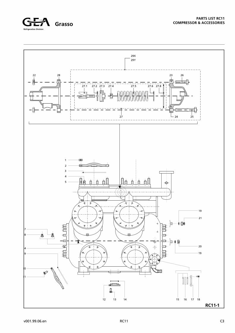
COMPRESSOR HOUSING WITH CONNECTIONS & OVERFLOW SAFETY VALVES FIG. RC11-1
1
2Aa2Ab3A
2Ba2Bb3B
457
8
9101112131415161718192021
22-2622232425or26
2727.127.227.327.427.527.627.8
28
29X29Y
Hex. nut M16For all types except 4-cyl. compressors:Cylinder cover 296PCylinder cover 296P-G13Oilit sealing ring 227x241x1.5Only in 4-cyl. compressors:Cylinder cover 556x296K110Cylinder cover 556x296K110-G13Oilit gasket 213x542x1.5For all types:Stud M16x35Stud M16x60Conical plug T13
Non-return valve 5
Oilit sealing ring 180x196x1.5Service cover 260Hex. head bolt M16x40Blind flange 60BAHex. head bolt M16x35Oilit sealing ring 67x81x1.5Oilit sealing ring 50x65x1.5Sight glass 65x15Sight glass cover 65Hex. head bolt M8x30Alu sealing ring 10x18x1Cap nut GK21RSocket coupling 6G21
Housing of safety valves 12/21 barHex. nut M10Housing top half 28x44Housing top half 28x30Hex. head bolt M10x60Hex. head bolt M10x55Hex. head bolt M10x40
Set of valve parts RC11-R-NH3Valve guide 29M10Valve disc 10x38x3Spring cup 22Lock nut M10Spring 7.5x37.5x9.5x129Adjustment ring 28x34x1Oilit sealing ring 77x87x1.5
Housing bottom half
Set of valve parts 12 bar LPSet of valve parts 21 bar HP
01.15.810
05.31.99605.31.99809.03.227
23.17.50023.17.51009.07.213
01.51.83501.51.86003.65.013
06.27.505
09.03.18005.31.26001.10.84005.05.96001.10.83509.03.06709.03.05012.26.06505.16.06501.10.43009.12.01001.17.02103.37.216
01.15.51048.13.03248.13.03101.10.56001.10.55501.10.540
48.27.52348.40.62909.42.38048.65.02201.45.50011.31.75711.15.27109.03.077
48.02.256
48.27.51348.27.521
--
------
222
----1
--
------14142212211
611224
111111--1
1
11
without temp. sensor plug holewith temp. sensor plug hole
without temp. sensor plug holewith temp. sensor plug hole
only in HP-cylinders of two-stage compressorsin all cylinders of single stagecompressors and in LP-cylinders of two-stage compressors
only in compressors with separate oilreservoir
on 12 bar-type valve onlyon 21 bar-type valve onlyon 21 bar-type valve onlyon 12 bar-type valve only
from compr. serial no. 82.10.6450 1)
Qty depends on adjustment
1) For compressors with a lower serial number, refer to the history parts list in this book.
Refrigeration Division
GrassoPARTS LIST RC11
COMPRESSOR & ACCESSORIES
C2 RC11 v001.99.06.en
RC11-1
Refrigeration Division
GrassoPARTS LIST RC11
COMPRESSOR & ACCESSORIES
v001.99.06.en RC11 C3

RC11-2
RC11-3
Refrigeration Division
GrassoPARTS LIST RC11
COMPRESSOR & ACCESSORIES
C4 RC11 v001.99.06.en
Item Description Ref. No. Qty Remarks
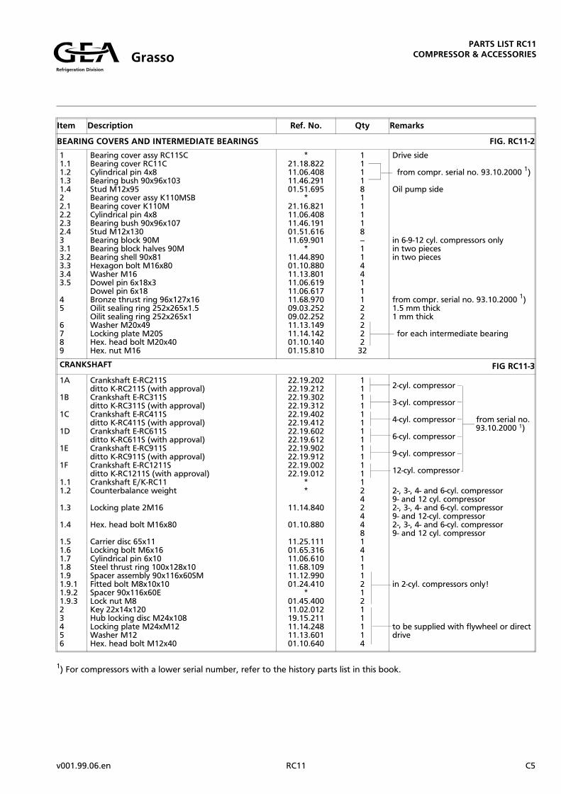
BEARING COVERS AND INTERMEDIATE BEARINGS FIG. RC11-2
11.11.21.31.422.12.22.32.433.13.23.33.43.5
45
6789
Bearing cover assy RC11SCBearing cover RC11CCylindrical pin 4x8Bearing bush 90x96x103Stud M12x95Bearing cover assy K110MSBBearing cover K110MCylindrical pin 4x8Bearing bush 90x96x107Stud M12x130Bearing block 90MBearing block halves 90MBearing shell 90x81Hexagon bolt M16x80Washer M16Dowel pin 6x18x3Dowel pin 6x18Bronze thrust ring 96x127x16Oilit sealing ring 252x265x1.5Oilit sealing ring 252x265x1Washer M20x49Locking plate M20SHex. head bolt M20x40Hex. nut M16
*21.18.82211.06.40811.46.29101.51.695
*21.16.82111.06.40811.46.19101.51.61611.69.901
*11.44.89001.10.88011.13.80111.06.61911.06.61711.68.97009.03.25209.02.25211.13.14911.14.14201.10.14001.15.810
1111811118--11441112222232
Drive side
from compr. serial no. 93.10.2000 1)
Oil pump side
in 6-9-12 cyl. compressors onlyin two piecesin two pieces
from compr. serial no. 93.10.2000 1)1.5 mm thick1 mm thick
for each intermediate bearing
CRANKSHAFT FIG RC11-3
1A
1B
1C
1D
1E
1F
1.11.2
1.3
1.4
1.51.61.71.81.91.9.11.9.21.9.323456
Crankshaft E-RC211Sditto K-RC211S (with approval)Crankshaft E-RC311Sditto K-RC311S (with approval)Crankshaft E-RC411Sditto K-RC411S (with approval)Crankshaft E-RC611Sditto K-RC611S (with approval)Crankshaft E-RC911Sditto K-RC911S (with approval)Crankshaft E-RC1211Sditto K-RC1211S (with approval)Crankshaft E/K-RC11Counterbalance weight
Locking plate 2M16
Hex. head bolt M16x80
Carrier disc 65x11Locking bolt M6x16Cylindrical pin 6x10Steel thrust ring 100x128x10Spacer assembly 90x116x60SMFitted bolt M8x10x10Spacer 90x116x60ELock nut M8Key 22x14x120Hub locking disc M24x108Locking plate M24xM12Washer M12Hex. head bolt M12x40
22.19.20222.19.21222.19.30222.19.31222.19.40222.19.41222.19.60222.19.61222.19.90222.19.91222.19.00222.19.012
**
11.14.840
01.10.880
11.25.11101.65.31611.06.61011.68.10911.12.99001.24.410
*01.45.40011.02.01219.15.21111.14.24811.13.60101.10.640
11111111111112424481411121211114
2-cyl. compressor
3-cyl. compressor
4-cyl. compressor from serial no. 93.10.2000 1)6-cyl. compressor
9-cyl. compressor
12-cyl. compressor
2-, 3-, 4- and 6-cyl. compressor9- and 12 cyl. compressor2-, 3-, 4- and 6-cyl. compressor9- and 12-cyl. compressor2-, 3-, 4- and 6-cyl. compressor9- and 12 cyl. compressor
in 2-cyl. compressors only!
to be supplied with flywheel or directdrive
1) For compressors with a lower serial number, refer to the history parts list in this book.
Refrigeration Division
GrassoPARTS LIST RC11
COMPRESSOR & ACCESSORIES
v001.99.06.en RC11 C5

Item Description Ref. No. Qty Remarks
PISTON AND CONNECTING ROD FIG. RC11-4
11.11.21.31.41.5
2a2.1a2.2a
2b2.1b2.2b2.3b
2.42.52.62.7
Piston assembly S160x50x160K110MGudgeon pin 36x50x148RC11PistonLocking plate M12SLocking bolt M12x35Set of piston rings
Con rod assembly S275RC11LDCon rod (aluminium alloy)Bearing bush 50x62x60
Con rod assembly S275RC11HDCon rod (aluminium alloy)Needle bearing NK50/25Distance bush 52x62x10
Bearing shell 90x53Con rod bolt MF16Retaining ring setHex. nut MF16
24.17.01124.18.320
*11.14.64201.44.63509.74.160
24.19.510*
11.46.652
24.19.520*
11.63.45111.16.562
11.44.59001.11.81011.39.80001.47.805
111111
--11
--121
1222
only in single-stage compressors and in LP-cylinders of two-stage compressors
from serial no. 80.10.....1)
only in HP-cylinders of two-stage compressors
CYLINDER AND VALVE LIFTING MECHANISM FIG. RC11-5
11.11.21.31.41.51.61.71.81.91.9.11.9.2
2
34566.16.279
Cylinder assembly 160RC11SCylinder liner 160RC11Hex. nut M6Pressure ring 160xD110Spring 2x10x27x110Supporting ring 160K110Spring wire 0.75x3.1Cylinder head screw M6x140Semi-circular lever K110Fork pin 6x55Split pin 1.5x10Washer
Oilit sealing ring 207x216x1Oilit sealing ring 207x216x1.25Oilit sealing ring 207x216x1.5Hex. head bolt M10x70O-ring 3.53x59.0Spring 3.2x25x3.5x42.5Control piston assembly RC11Control piston 51x39O-ring 3.5x44Piston housing K110Nipple coupling 6G13
23.19.11023.18.01001.15.31027.16.51011.31.20927.16.57011.32.08101.68.31427.16.61011.07.35511.08.01011.13.301
09.02.20609.01.20609.03.20601.10.57009.52.37611.31.32527.18.670
*09.52.35027.16.65003.38.136
114121121111
11141111111
2)
1 mm thick1.25 mm thick1.5 mm thick
not to be used for HP-cylinders of two-stage compressors!
1) For compressors with a lower serial number, refer to the history parts list in this book.
2) from compr. serial no. 89.08.2100 the two threaded holes M6 in the pressure ring to fix the cylinder head screws (item 1.7, Ref. No. 01.68.314) are replaced by non-threaded holes with a dia. of 6.8 mm.
Refrigeration Division
GrassoPARTS LIST RC11
COMPRESSOR & ACCESSORIES
C6 RC11 v001.99.06.en

RC11-5
RC11-4
Refrigeration Division
GrassoPARTS LIST RC11
COMPRESSOR & ACCESSORIES
v002.00.01.en RC11 C7
RC11-7
RC11-6
Refrigeration Division
GrassoPARTS LIST RC11
COMPRESSOR & ACCESSORIES
C8 RC11 v001.99.06.en
Item Description Ref. No. Qty Remarks
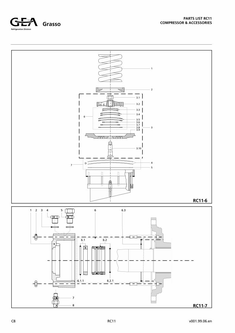
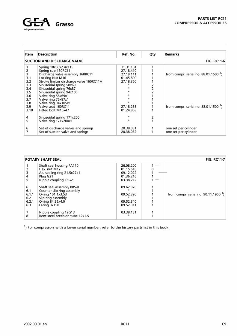
SUCTION AND DISCHARGE VALVE FIG. RC11-6
1233.13.23.33.43.53.63.73.83.93.10
45
67
Spring 18x88x2.4x115Spring cup 160RC11Discharge valve assembly 160RC11Locking Nut M16Stroke limitor discharge valve 160RC11ASinusoidal spring 58x69Sinusoidal spring 76x87Sinusoidal spring 94x105Valve ring 58x69x1Valve ring 76x87x1Valve ring 94x105x1Valve seat 160RC11Fitted bolt M16x47
Sinusoidal spring 171x200Valve ring 171x200x1
Set of discharge valves and springsSet of suction valve and springs
11.31.18127.18.41027.19.11101.45.80027.18.360
******
27.18.26501.24.863
**
20.38.03120.38.032
1111122211111
21
11
from compr. serial no. 88.01.1500 1)
from compr. serial no. 88.01.1500 1)
one set per cylinderone set per cylinder
ROTARY SHAFT SEAL FIG. RC11-7
12345
66.16.1.16.26.2.16.3
78
Shaft seal housing FA110Hex. nut M12Alu sealing ring 21.5x27x1Plug G21Nipple coupling 16G21
Shaft seal assembly 085-BCounter-slip ring assemblyO-ring 101.1x3.53Slip ring assemblyO-ring 84.95x4.0O-ring 3x150
Nipple coupling 12G13Bent steel precision tube 12x1.5
26.08.20001.15.61009.12.02201.36.21603.38.212
09.62.920*
09.52.390*
09.52.34009.52.311
03.38.131*
18111
111111
11
from compr. serial no. 90.11.1950 1)
1) For compressors with a lower serial number, refer to the history parts list in this book.
Refrigeration Division
GrassoPARTS LIST RC11
COMPRESSOR & ACCESSORIES
v002.00.01.en RC11 C9

Item Description Ref. No. Qty Remarks
OIL PUMP FIG. RC11-8
- For all compressor types except types RC5111 and RC10211 with a serial number of 89.03.1200 and over:
1A1.1A1.8A
Gear pump RC11Pump housing RC11AControl plunger 12RC11A
18.10.18526.18.51026.08.915
111
- For compressor types RC5111 and RC10211 irrespective of the serial number:
1B1.1B1.8B
Gear pump RC11Pump housing RC11Control plunger B FA110M
18.10.18026.18.50026.08.911
111
- For all compressor types irrespective of the serial number:
1.21.31.41.51.61.71.81.91.101.111.11A1.121.13 or1.141.151.161.171.181.191.201.211.221.231.241.25
23
Gear wheel 4x9 D18Gear wheel 4x9 D18Bearing bush 18x24x61O-ring 5.33x146.1Pump cover RC11Hex. head bolt M6x20See aboveControl piston 24K110MPlunger 10K110MPiston assembly 30K110Piston assembly 30K110GSpring 1.1x15x15x97Alu sealing ring 34x44x1O-ring 3x33Plug G33Plunger 14K110MSpring 2.1x11.3x13.5x70.5Alu sealing ring 17x21x1Plug G17Alu sealing ring 13.5x20x1Plug G13SNipple coupling 6G13Alu sealing ring 6.5x11x1Hex. head bolt M6x10Tee-coupling E6x6x6Cylindrical pin 6x12
Hex. nut M12O-ring 3x150
19.37.80919.37.85911.46.71809.52.54426.18.60001.10.320
26.16.82126.16.80126.17.83026.17.83511.31.11709.12.03409.52.30001.36.33626.16.81111.31.22209.12.01601.36.17609.12.01401.36.13403.38.13609.12.00701.10.31003.40.30611.06.612
01.15.61009.52.311
112112
1111111111111121111
81
obtainable as complete set only
Differential pressure regulator
Hydraulic relayHydraulic relay (with hole)*
Relief valve
* Contact Grasso Service & Parts Dept.
Refrigeration Division
GrassoPARTS LIST RC11
COMPRESSOR & ACCESSORIES
C10 RC11 v001.99.06.en

RC11-8
Refrigeration Division
GrassoPARTS LIST RC11
COMPRESSOR & ACCESSORIES
v001.99.06.en RC11 C11

aaaaaa
RC11-9
Refrigeration Division
GrassoPARTS LIST RC11
COMPRESSOR & ACCESSORIES
C12 RC11 v001.99.06.en
Item Description Ref. No. Qty Remarks
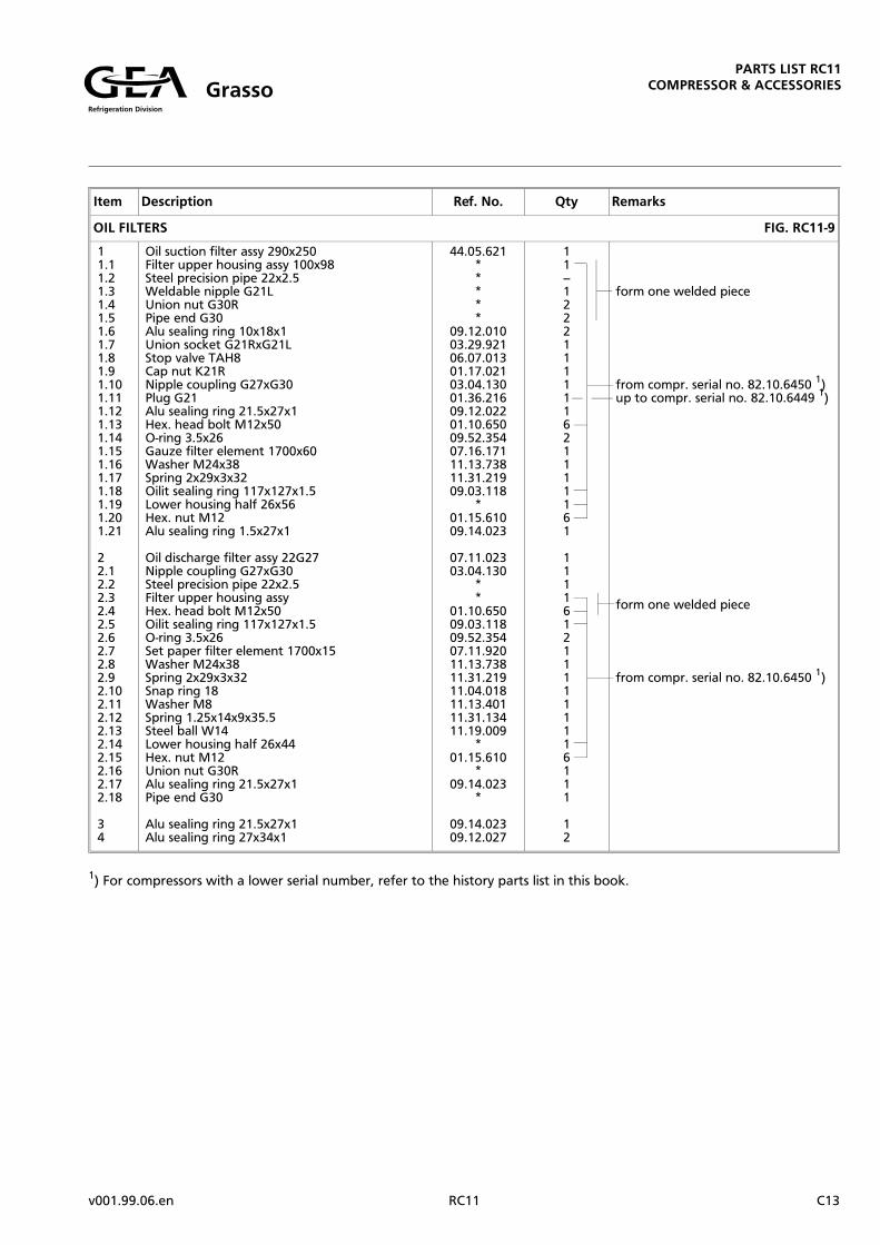
OIL FILTERS FIG. RC11-9
11.11.21.31.41.51.61.71.81.91.101.111.121.131.141.151.161.171.181.191.201.21
22.12.22.32.42.52.62.72.82.92.102.112.122.132.142.152.162.172.18
34
Oil suction filter assy 290x250Filter upper housing assy 100x98Steel precision pipe 22x2.5Weldable nipple G21LUnion nut G30RPipe end G30Alu sealing ring 10x18x1Union socket G21RxG21LStop valve TAH8Cap nut K21RNipple coupling G27xG30Plug G21Alu sealing ring 21.5x27x1Hex. head bolt M12x50O-ring 3.5x26Gauze filter element 1700x60Washer M24x38Spring 2x29x3x32Oilit sealing ring 117x127x1.5Lower housing half 26x56Hex. nut M12Alu sealing ring 1.5x27x1
Oil discharge filter assy 22G27Nipple coupling G27xG30Steel precision pipe 22x2.5Filter upper housing assyHex. head bolt M12x50Oilit sealing ring 117x127x1.5O-ring 3.5x26Set paper filter element 1700x15Washer M24x38Spring 2x29x3x32Snap ring 18Washer M8Spring 1.25x14x9x35.5Steel ball W14Lower housing half 26x44Hex. nut M12Union nut G30RAlu sealing ring 21.5x27x1Pipe end G30
Alu sealing ring 21.5x27x1Alu sealing ring 27x34x1
44.05.621*****
09.12.01003.29.92106.07.01301.17.02103.04.13001.36.21609.12.02201.10.65009.52.35407.16.17111.13.73811.31.21909.03.118
*01.15.61009.14.023
07.11.02303.04.130
**
01.10.65009.03.11809.52.35407.11.92011.13.73811.31.21911.04.01811.13.40111.31.13411.19.009
*01.15.610
*09.14.023
*
09.14.02309.12.027
11--1222111111621111161
1111612111111116111
12
form one welded piece
from compr. serial no. 82.10.6450 1)up to compr. serial no. 82.10.6449 1)
form one welded piece
from compr. serial no. 82.10.6450 1)
1) For compressors with a lower serial number, refer to the history parts list in this book.
Refrigeration Division
GrassoPARTS LIST RC11
COMPRESSOR & ACCESSORIES
v001.99.06.en RC11 C13

Item Description Ref. No. Qty Remarks
LUBRICATING OIL LINES FIG. RC11-10
1
1.11.21.31.41.51.61.71.81.91.101.111.121.131.141.15
2.12.22.3
3
3.13.23.33.4
456
Oil return line G21x147S
(replaced by item 6)Alu sealing ring 21.5x27x1Nipple coupling 16G21Steel precision pipe K16x2Union nut G21Pipe end G21Steel pipe K13.5x2.35Valve housing H9KBall W16Spring 1.25x14x9x35.5Thrust bolt G21x60SO-ring 1.78x8.73Nipple G21CxG21Alu sealing ring 10x18x1Cap nut GK21R
Steel precision pipe K16x2Swivel coupling 16G21Alu sealing ring 23.5x30x1
Oil discharge pressure line 16x573SOil discharge pressure line 16x573Oil discharge pressure line 16x814Oil discharge pressure line 16x963Oil discharge pressure line 16x1354Oil discharge pressure line 16x1744Swivel coupling 16G21Steel precision pipe K16x2Nipple coupling 16G21Alu sealing ring 23.5x30x1
Alu sealing ring 27x34x1Alu sealing ring10x18x1Socket nipple G21xG27
44.05.922
09.14.02303.38.212
*03.23.02103.24.021
*48.03.01011.19.01011.31.13401.35.21809.52.18403.04.92109.12.01001.17.021
04.38.16503.39.21609.12.024
44.05.72044.05.73044.05.74044.05.76044.05.79044.05.70003.39.216
*03.38.21209.12.024
09.12.02709.12.01003.02.927
1
11111111111111
111
1111111111
111
lubricating oil pressure regulatorincluded
form one welded piece
2-cylinder compressor3-cylinder compressor4-cylinder compressor6-cylinder compressor9-cylinder compressor12-cylinder compressor
Refrigeration Division
GrassoPARTS LIST RC11
COMPRESSOR & ACCESSORIES
C14 RC11 v001.99.06.en

RC11-10
Refrigeration Division
GrassoPARTS LIST RC11
COMPRESSOR & ACCESSORIES
v001.99.06.en RC11 C15

RC11-11
Refrigeration Division
GrassoPARTS LIST RC11
COMPRESSOR & ACCESSORIES
C16 RC11 v001.99.06.en

Item Description Ref. No. Qty Remarks
SUCTION GAS STRAINER FIG. RC11-11
11.11.2
2A3A4A5A6A7A
2B3B4B5B6B7B
8A9A10A
8B9B10B
8C9C10C
8D9D10D
Strainer housingWeldable coupling 16x21Weldable coupling 6x11
Oilit sealing ring 124x136x1.5Cover 185Hex. head bolt M12x40Strainer element 1700x110Cover 185PSpring 6x40x2.7x42
Oilit sealing ring 180x196x1.5Cover 260Hex. head bolt M16x40Strainer element 3200x110Cover 260PSpring 6x40x2.7x42
Hex. nut M16Oilit sealing ring 84x98x1.5Hex. head bolt M16x60
Hex. nut M20Oilit sealing ring 117x131x1.5Hex. head bolt M20x70
Hex. nut M20Oilit sealing ring 143x161x1.5Hex. head bolt M20x70
Hex. nut M20Oilit sealing ring 169x187x1.5Hex. head bolt M20x70
*03.35.01603.35.006
09.03.12405.30.18501.85.64007.16.17005.30.99511.13.601
09.03.18005.31.26101.10.84007.16.32005.31.96111.31.601
01.15.81009.03.08401.10.860
01.15.11009.03.11701.10.170
01.15.11009.03.14301.10.170
01.15.11009.03.16901.10.170
111
2116111
2116111
828
828
828
828
2-, 3- and 4-cyl. compressor
6-, 9- and 12-cyl. compressor
RC211, 311, 411 and 2111
RC611, 4211 and 5111
RC911, 10211, 8411 and 9311
RC1211 only
Refrigeration Division
GrassoPARTS LIST RC11
COMPRESSOR & ACCESSORIES
v001.99.06.en RC11 C17
Item Description Ref. No. Qty Remarks
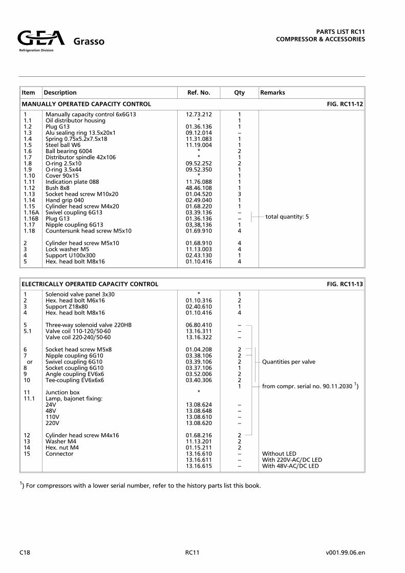
MANUALLY OPERATED CAPACITY CONTROL FIG. RC11-12
11.11.21.31.41.51.61.71.81.91.101.111.121.131.141.151.16A1.16B1.171.18
2345
Manually capacity control 6x6G13Oil distributor housingPlug G13Alu sealing ring 13.5x20x1Spring 0.75x5.2x7.5x18Steel ball W6Ball bearing 6004Distributor spindle 42x106O-ring 2.5x10O-ring 3.5x44Cover 90x15Indication plate 088Bush 8x8Socket head screw M10x20Hand grip 040Cylinder head screw M4x20Swivel coupling 6G13Plug G13Nipple coupling 6G13Countersunk head screw M5x10
Cylinder head screw M5x10Lock washer M5Support U100x300Hex. head bolt M8x16
12.73.212*
01.36.13609.12.01411.31.08311.19.004
**
09.52.25209.52.350
*11.76.08848.46.10801.04.52002.49.04001.68.22003.39.13601.36.13603,38,13601.69.910
01.68.91011.13.00302.43.13001.10.416
111--112121111311----14
4414
total quantity: 5
ELECTRICALLY OPERATED CAPACITY CONTROL FIG. RC11-13
1234
55.1
67 or8910
1111.1
12131415
Solenoid valve panel 3x30Hex. head bolt M6x16Support Z18x80Hex. head bolt M8x16
Three-way solenoid valve 220HBValve coil 110-120/50-60Valve coil 220-240/50-60
Socket head screw M5x8Nipple coupling 6G10Swivel coupling 6G10Socket coupling 6G10Angle coupling EV6x6Tee-coupling EV6x6x6
Junction boxLamp, bajonet fixing:24V48V110V220V
Cylinder head screw M4x16Washer M4Hex. nut M4Connector
*01.10.31602.40.61001.10.416
06.80.41013.16.31113.16.322
01.04.20803.38.10603.39.10603.37.10603.52.00603.40.306
*
13.08.62413.08.64813.08.61013.08.620
01.68.21611.13.20101.15.21113.16.61013.16.61113.16.615
1214
------
2221221
--------
222------
Quantities per valve
from compr. serial no. 90.11.2030 1)
Without LEDWith 220V-AC/DC LEDWith 48V-AC/DC LED
1) For compressors with a lower serial number, refer to the history parts list this book.
Refrigeration Division
GrassoPARTS LIST RC11
COMPRESSOR & ACCESSORIES
C18 RC11 v001.99.06.en

RC11-13
RC11-12
Refrigeration Division
GrassoPARTS LIST RC11
COMPRESSOR & ACCESSORIES
v001.99.06.en RC11 C19
RC11-14
RC11-15
Refrigeration Division
GrassoPARTS LIST RC11
COMPRESSOR & ACCESSORIES
C20 RC11 v001.99.06.en
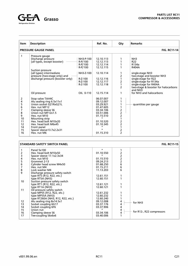
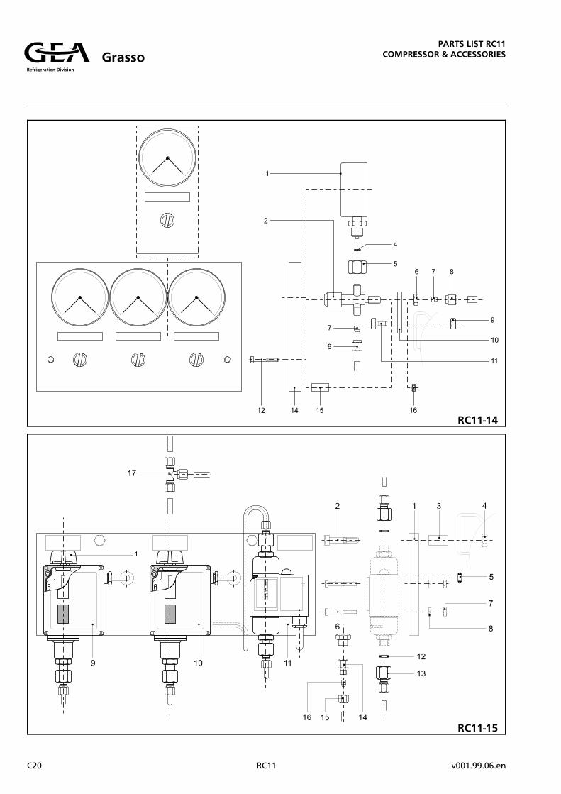
STANDARD SAFETY SWITCH PANEL FIG. RC11-15
123456789
10
11
121314151617
Panel 5x100Hex. head bolt M10x50Spacer sleeve 17.1x2.3x34Hex. nut M10Grommet 2-13Cylinder head screw M4x50Hex. nut M4Lock washer M4Discharge pressure safety switchtype RT5 (R12, R22, etc.)type RT5A (NH3)Suction pressure safety switchtype RT1 (R12, R22, etc.)type RT1A (NH3)Oil pressure safety switchtype MP55 (R12, R22, etc.)type MP55A (NH3)type RT260A (NH3, R12, R22, etc.)Alu sealing ring 8x14.5x1Socket coupling 6G17Socket coupling 6F6Union nutClamping sleeve S6Tee-coupling S6x6x6
*01.10.550
*01.15.51009.24.21301.68.25001.15.21111.13.203
12.61.15112.60.151
12.61.12112.60.121
12.61.23212.60.23212.60.24009.12.00803.37.17603.37.906
*03.34.10603.40.006
12222666
11
11
111444441
for NH3
for R12-, R22 compressors
Item Description Ref. No. Qty Remarks
PRESSURE GAUGE PANEL FIG. RC11-14
1
2456789101112141516
Pressure gaugeDischarge pressure (all types, except booster)
Suction pressure(all types) intermediatepressure (two-stage only) anddischarge pressure (booster only)
Oil pressure
Stop valve TAH4CAlu sealing ring 6.5x11x1Union socket G21RxG21LHex. nut MF12Clamping sleeve S6Union nut MF12x1.5Hex. nut M10Mounting stripHex. head bolt M10x20Hex. head bolt M6x45Front panelSpacer sleeve13.7x2.2x31Hex. nut M6
NH3-P-100R-P/100R-P/100R-P/100
NH3-Z-100
R-Z-100R-Z-100R-Z-100
OIL 0-110
12.10.11312.12.11312.12.11412.12.115
12.10.114
12.12.11612.12.11712.12.118
12.15.114
06.07.00709.12.00703.29.92101.47.60503.34.10603.51.00601.15.510
*01.10.52001.10.345
**
01.15.310
1111
121212
1
1111222122122
NH3R22R134aR404A
single-stage NH3two-stage and booster NH3single-stage for R22single-stage for R134asingle-stage for R404Atwo-stage & booster for halocarbonsand NH3for NH3 and halocarbons
quantities per gauge
Refrigeration Division
GrassoPARTS LIST RC11
COMPRESSOR & ACCESSORIES
v001.99.06.en RC11 C21

Item Description Ref. No. Qty Remarks
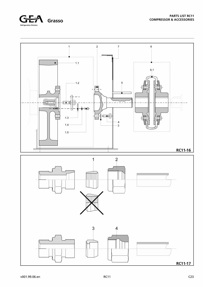
DIRECT DRIVE FIG. RC11-16
11.11.21.31.41.5
2345
6A6.1A
6B6.1B
6C6.1C
7A7B
Flywheel 0x772x166FPCSFlywheel 0x722x166FPCHub locking disc M24x108Locking plate M24xM12Washer M12Hex. head bolt M12x35
Flange shaft 84x322x230x150Locking plate M20Hex. head bolt M20x60Key 22x14x160
Coupling type 25-1 (machined)Waved band 225X
Coupling type 26-1 (machined)Waved band 426X
Coupling type 28-1 (machined)Waved band 828X
Coupling guard 800x660x370Coupling guard 800x700x370
19.13.714*
19.15.21111.14.24811.13.60101.10.635
19.63.08711.13.10201.10.16011.02.016
*19.18.938
*19.18.939
*19.18.955
**
for coupling type 25-1 & 26-1for coupling 28-1
PARTS FOR CLAMP COUPLINGS FIG. RC11-17
1A2A
1B2B
1C2C
34
Clamping sleeve P6Union nut M12x1.5 (DIN 2353)
Union nut M14x1.5 (DIN 2353)
Clamping sleeve P16Union nut M24x1.5 (DIN 2353)
Clamping sleeve P22Union nut M30x2 (DIN 2353)
Clamping sleeve S6Union nut MF12x1.5 (special)
03.34.506*
*
03.34.516*
03.34.522*
03.34.10603.51.006
----
--
----
----
----
to be used on clamp couplings withreference number:
03.36.00603.36.90603.37.10603.37.17603.38.13103.38.13603.39.13603.40.00603.40.306
03.35.00603.37.216
03.35.01603.38.21203.39.216
03.38.272
03.52.00603.54.076
Refrigeration Division
GrassoPARTS LIST RC11
COMPRESSOR & ACCESSORIES
C22 RC11 v001.99.06.en
RC11-17
RC11-16
Refrigeration Division
GrassoPARTS LIST RC11
COMPRESSOR & ACCESSORIES
v001.99.06.en RC11 C23

RC11-18
Refrigeration Division
GrassoPARTS LIST RC11
COMPRESSOR & ACCESSORIES
C24 RC11 v001.99.06.en

COMPRESSOR (LP) SUCTION LP DISCHARGE HP SUCTION (HP) DISCHARGE
FIG. RC11-18 FLANGE NO. 1 FLANGE NO. 2 FLANGE NO. 3 FLANGE NO. 4
MODEL SIZE PART NO. SIZE PART NO. SIZE PART NO. SIZE PART NO.
RC211
SIN
GLE S
TA
GE
84x98x1.5 09.03.084 67x81x1.5 09.03.067
RC311 98x112x1.5 09.03.098 67x81x1.5 09.03.067
RC411 98x112x1.5 09.03.098 98x112x1.5 09.03.098
RC611 117x131x1.5 09.03.117 98x112x1.5 09.03.098
RC911 143x161x1.5 09.03.143 117x131x1.5 09.03.117
RC1211 169x187x1.5 09.03.169 117x131x1.5 09.03.117
RC2111
TW
O-S
TA
GE
98x112x1.5 09.03.098 67x81x1.5 09.03.067 67x81x1.5 09.03.067 84x98x1.5 09.03.084
RC3111 98x112x1.5 09.03.098 98x112x1.5 09.03.098 67x81x1.5 09.03.067 84x98x1.5 09.03.084
RC4211 117x131x1.5 09.03.117 84x98x1.5 09.03.084 84x98x1.5 09.03.084 67x81x1.5 09.03.067
RC5111 117x131x1.5 09.03.117 98x112x1.5 09.03.098 84x98x1.5 09.03.084 84x98x1.5 09.03.084
RC6311 117x131x1.5 09.03.117 117x131x1.5 09.03.117 117x131x1.5 09.03.117 67x81x1.5 09.03.067
RC7211 143x161x1.5 09.03.143 117x131x1.5 09.03.117 117x131x1.5 09.03.117 67x81x1.5 09.03.067
RC8411 143x161x1.5 09.03.143 117x131x1.5 09.03.117 117x131x1.5 09.03.117 67x81x1.5 09.03.067
RC9311 143x161x1.5 09.03.143 117x131x1.5 09.03.117 117x131x1.5 09.03.117 67x81x1.5 09.03.067
RC10211 143x161x1.5 09.03.143 117x131x1.5 09.03.117 117x131x1.5 09.03.117 67x81x1.5 09.03.067
Item Description Ref. No. Qty Remarks
STANDARD SETS OF PARTS, SEALS AND TOOLS NO FIGURE
1 Set of special tools 20.18.010 1
2 Sets of spare parts (including gaskets and seals)Basic set
Additional set (per 3 cylinders)Additional set (per 4 cylinders)
20.18.021
20.18.03120.18.041
1
11
for all types except RC411 & RC3111
for 6-9-12 cyl. compressorfor types RC411 & RC3111
3 Set of gaskets and sealsAdditional set of gaskets and seals (per3 cylinders)Set of gaskets and seals
09.90.012
09.90.01309.90.014
1
11
for all types except RC411 & RC3111
for 6-9-12 cylinder compressorsfor types RC411 & RC3111
OILIT SEALING RINGS FOR SUCTION-, INTERMEDIATE AND DISCHARGE CONNECTIONS (FIG. RC11-18)
Refrigeration Division
GrassoPARTS LIST RC11
COMPRESSOR & ACCESSORIES
v002.00.01.en RC11 C25

Refrigeration Division
GrassoPARTS LIST RC11
COMPRESSOR & ACCESSORIES
C26 RC11 v001.99.06.en

The history parts list on the following pages may only be used when it is expressly referred to by the standard list
also included in this booklet. The reference is given via a foot note.
The fact is that this history parts list contains all those parts and (sub)assemblies that are no longer used in standard compressors as delivered by the works, but, be it sometimes for a limitid period, are still available for subsequent delivery.
If suchs parts or (sub)assemblies are fully interchangeable with any corresponding new items introduced from a certain serial number, this is shown on the relevant page of this history parts list. It should be noted, however, thatfor compressors thus adapted in the field, the serial number no longer can be referred to in repeat orders for spareparts.
For the use of the history parts list with the corresponding illustrations and how to order parts, reference is madeto page 1 of the standard parts list.Mind that in the table below, which is meant to be used for quick retrieval of the required parts, the sequence ofthe group of parts and of the page and figure numbers may be different from those in the standard parts list.
GROUP OF PARTSPARTS LISTPage No.:
CORRESPONDING FIGURENo.:
o Overflow safety valve 2 RC11-H1
o Connecting rod 2 RC11-H2
o Oil filters 5 RC11-H3
o Rotary shaft seal 5 RC11-H4
o Suction and discharge valve 6 RC11-H5
o Electrically operated capacity control 6 RC11-H6
o Bearing covers 9 RC11-H7
o Crankshaft 9 RC11-H8
PARTS LIST RC11
HISTORYRefrigeration Division
Grasso
v001.99.06.en RC11 H1

Item Description Ref. No. Qty Remarks
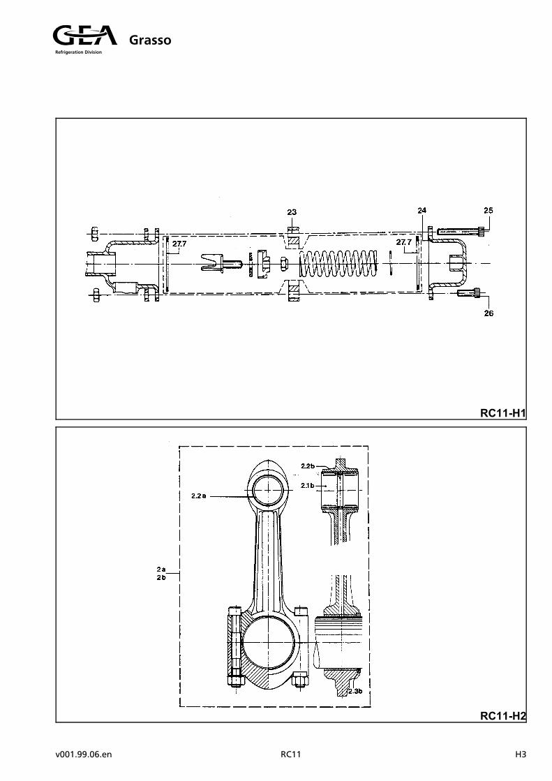
OVERFLOW SAFETY VALVE FIG. RC11-H1
23242526 or27.7
Distance ring 109x68x11Housing top half 28x21x8Socket head screw M10x60Socket head screw M10x25Socket head screw M10x40Gasket 69x79x2
**
01.04.56001.04.52501.04.54009.04.069
112662
on 12 bar-type only 1)
on 22.5 bar-type valveon 12 bar-type valve
CONNECTING ROD FIG. RC11-H2
2a2.2a
2b2.1b2.2b2.3b
Con rod assembly S90x275FA110Bearing bush 50/58
Con rod assembly 90x275RC11HDNeedle bearing NK50/25Disctance ring 52x62x10Alu ring 109x96
24.08.50011.46.650
24.19.55011.63.45111.16.56298.00.699
--1
--211
only in single stage compressorsand in LP-cylinders of two-stagecompressors
only in HP-cylinders of two-stagecompressors
1) This item (23) is of stock. This means that the valve bottom and top half (incl. fasteners and excl. the internal items) must
be exchanged by the modified items as mentioned in the compressor spare parts list for compressors with serial num-
bers from 82.10.6450 and over.
PARTS LIST RC11
HISTORYRefrigeration Division
Grasso
H2 RC11 v001.99.06.en
RC11-H1
RC11-H2
Refrigeration Division
Grasso
v001.99.06.en RC11 H3

RC11-H3
RC11-H4
PARTS LIST RC11
HISTORYRefrigeration Division
Grasso
H4 RC11 v001.99.06.en

Item Description Ref. No. Qty Remarks
OIL FILTERS FIG. RC11-H3
Oil suction filter:
1.11.131.181.191.20
Filter top halfSocket head screw M10x20Gasket 109x119x2Filter bottom halfHex. nut M10
*01.04.52009.04.109
*01.15.510
1121112
Oil discharge filter:
2.32.42.52.142.15
Filter top halfSocket head screw M10x20Gasket 109x119x2Filter bottom halfHex. nut M10
*01.04.52009.04.109
*01.15.510
1121112
ROTARY SHAFT SEAL Ref. No.: 09.62.086 FIG. RC11-H4
66.16.2
Shaft seal assembly 85MOO-ring 7.5x95O-ring 7x85
*09.52.75609.52.704
111
1)
ROTARY SHAFT SEAL Ref. No.: 09.62.286 FIG. RC11-H5
66.16.2
Shaft seal assembly CK85O-ring 7.5x95O-ring 7x85
*09.52.75609.52.704
111
1)
1) This subassembly (item 6) is replaced completely by the subassembly with Ref. No. 09.62.290 as mentioned in the
compressor spare parts list for compressors serial numbers 90.11.1950 and over.
PARTS LIST RC11
HISTORYRefrigeration Division
Grasso
v001.99.06.en RC11 H5

Item Description Ref. No. Qty Remarks
SUCTION AND DISCHARGE VALVE FIG. RC11-H5
33.9
4(5)
Discharge valve assembly 160RC11Discharge valve seat 160RC11A
Stroke limitor, suction valve 160RC11AAlu sealing ring 201x214x1
27.19.11027.18.261
27.18.31109.12.201
11
1(1)
1)
ELECTRICALLY OPERATED CAPACITY CONTROL FIG. RC11-H6
56712
Three-way solenoid valve 220HASocket head screw M6x10Nipple coupling 6G13Cylinder head screw M4x20
*01.04.31003.38.13601.68.220
--222
2)
1) This subassembly (item 3) and items 4 and (5) can be replaced completely by the subassembly with Ref. No.: 27.19.111
as mentioned in the compressor spare parts list for compressors with serial numbers from 88.01.1500 and over.
2) This valve (item 5) is replaced by the valve with Ref. No.: 06.80.410 as mentioned in the compressor spare parts list for
compressors with serial numbers from 90.11.2030 and over.
PARTS LIST RC11
HISTORYRefrigeration Division
Grasso
H6 RC11 v001.99.06.en

RC11-H5
RC11-H6
PARTS LIST RC11
HISTORYRefrigeration Division
Grasso
v001.99.06.en RC11 H7

RC11-H7
RC11-H8
PARTS LIST RC11
HISTORYRefrigeration Division
Grasso
H8 RC11 v001.99.06.en
Item Description Ref. No. Qty Remarks
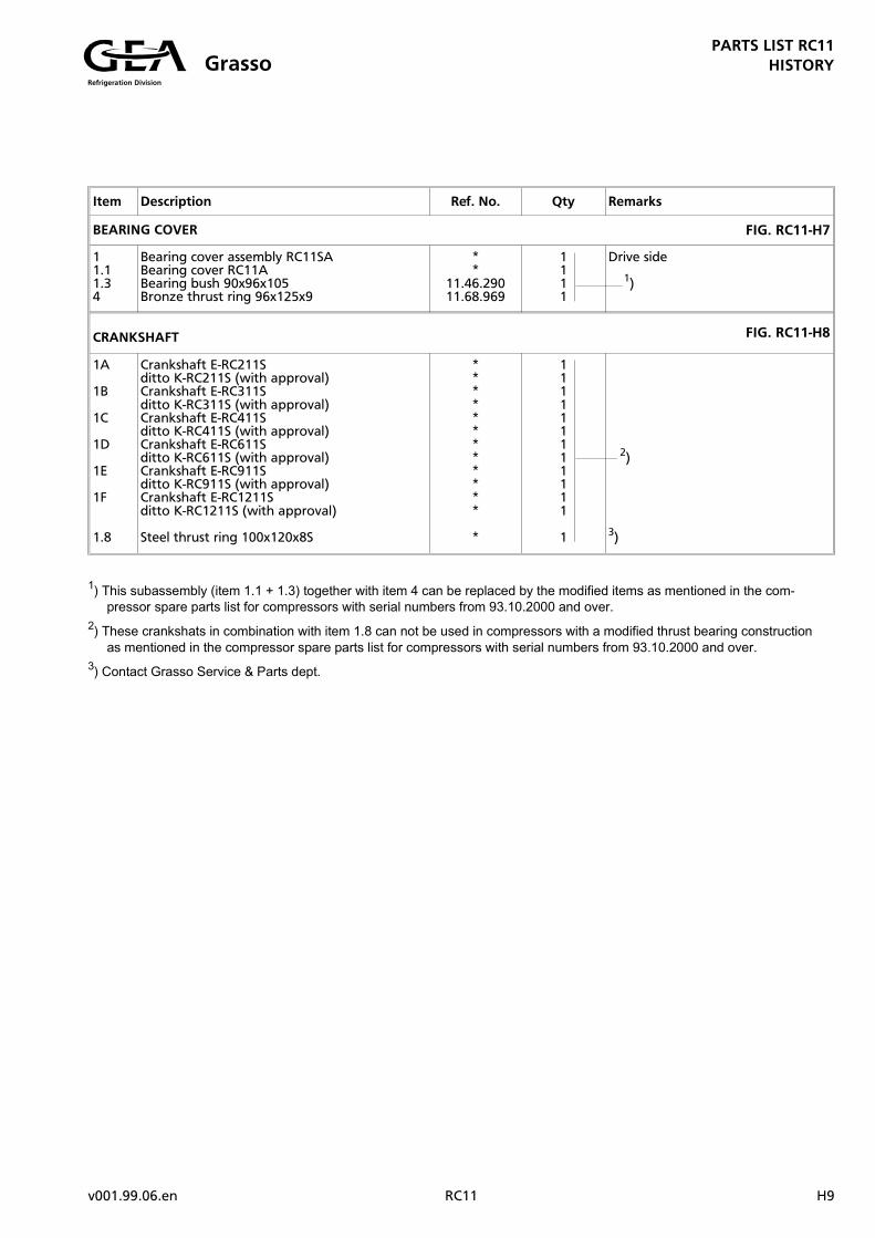
BEARING COVER FIG. RC11-H7
11.11.34
Bearing cover assembly RC11SABearing cover RC11ABearing bush 90x96x105Bronze thrust ring 96x125x9
**
11.46.29011.68.969
1111
Drive side
1)
CRANKSHAFT FIG. RC11-H8
1A
1B
1C
1D
1E
1F
1.8
Crankshaft E-RC211Sditto K-RC211S (with approval)Crankshaft E-RC311Sditto K-RC311S (with approval)Crankshaft E-RC411Sditto K-RC411S (with approval)Crankshaft E-RC611Sditto K-RC611S (with approval)Crankshaft E-RC911Sditto K-RC911S (with approval)Crankshaft E-RC1211Sditto K-RC1211S (with approval)
Steel thrust ring 100x120x8S
************
*
111111111111
1
2)
3)
1) This subassembly (item 1.1 + 1.3) together with item 4 can be replaced by the modified items as mentioned in the com-
pressor spare parts list for compressors with serial numbers from 93.10.2000 and over.
2) These crankshats in combination with item 1.8 can not be used in compressors with a modified thrust bearing construction
as mentioned in the compressor spare parts list for compressors with serial numbers from 93.10.2000 and over.
3) Contact Grasso Service & Parts dept.
PARTS LIST RC11
HISTORYRefrigeration Division
Grasso
v001.99.06.en RC11 H9

PARTS LIST RC11
HISTORYRefrigeration Division
Grasso
H10 RC11 v001.99.06.en

Refrigeration Division
Grasso
RC11 v001.99.06

Grasso Products B.V. P.O. Box 343 •••• 5201 AH ’s-Hertogenbosch •••• The NetherlandsPhone: +31 (0)73 - 6203 911 •••• Fax: +31 (0)73 - 6231 286 •••• E-Mail: [email protected]
Grasso GmbH Holzhauser Straße - 165 •••• 13509 Berlin •••• GermanyRefrigeration Technology Phone: +49 (0)30 - 43 592 6 •••• Fax: +49 (0)30 - 43 592 777
Please contact your office: