research on key energy-saving techniques for a novel full
TRANSCRIPT

Research on Key Energy-saving Techniques for A Novel Full Air Cooling UV-curing Oven via CFD Approach
WU Shang-sheng1, a *, YU Zhong-ming1,b and Chen Jian-you 2,c 1 School of Mechanical and Automotive Engineering, South China University of Technology,
Guangzhou 510640, China 2 Guang Zhou Yxin Packaging Machinery Co., Ltd., Guangzhou 511486, China
[email protected], [email protected], c [email protected]
Keywords: energy-saving; curing oven; optimum design; Computational Fluid Dynamics (CFD). Abstract. The optimum design of a novel full air cooling UV-curing oven is proposed, to overcome the disadvantage of traditional drying ovens on the high energy consumption and inefficiency, at al. The optimum curing oven is simulated and analyzed by Fluent applied to the CFD technology. Comparison between the simulation and real data indicates that the CFD model has an accurate prediction. The optimum wind velocity of the inlet is 1 m/s. A general optimum design method of the curing oven is put forward as well. The specific energy analysis shows that, energy consumption of the glazing machine with the optimum curing oven have decreased by approximately 14% compared to the conventional ones.
Introduction The common UV-curing ink generally consists of oligomer, reactive diluent (the water-based ink’s
reactive diluent usually contains three parts: water, photo initiator and additives). Above all, the initiation efficiency of photo initiator matters extremely to the curing rate. According to the Lambert-Beer law, either the initiator concentration is too low or too high will result in the curing rate’s dropping [1-4]. Song et al.[5], using the double-bonds conversion testing method to gain the curing rate, considered that using the high-power output UV lights contributed much to improve the curing system’s energy efficiency. However, UV lights have a strong thermal effect. Only about 30% of the whole energy consumption converses to ultraviolet rays. And the rest is conversed to infrared rays and other, which will decline the pressing’s quality. Preetham P. and Ashok G.’s research [6] indicated that, to minimize lighting frequency contributed to the energy saving. Under forced convection conditions, steam generated during the UV curing reaction was taken away with wind fluid, which contributed to raise the curing rate of UV inks [7]. The excessive ambient air temperature usually caused the pressing’s being out of shape or yellowing. Huang, et al. considered the reutilization of hot air and cooling water contributed to the energy saving [8]. In view of that the reutilization of hot air might cause that the water vapor content in the air-cooling equipment increasing in the actual production process, and then deteriorating the printing’s quality, most manufacturers did not choose the hot air recycling. Although the LED-UV reduced the energy consumption without doubt[9], the domestic LED-UV ink matching with it was not yet fully developed, which leaded to high cost and not being used widely. The conventional cooling method of UV-curing equipment was generally water cooling + air cooling, whose energy consumption was huge. Besides, the complex structure was apparently not beneficial to the installation of the oven. CFD is an effective tool to visual the behavior inside the curing oven. The combined experiment and CFD method makes the computational parameters more accurate [10, 11].
This paper presents a novel design of UV curing oven with all air cooling. Comparison between the experiment and simulation of the curing oven is investigated, in order to put forward a general method to establish the proper CFD model of oven. Based on this, the specific energy of the glazing machine with this new oven and the conventional ones are discussed.
International Conference on Manufacturing Science and Engineering (ICMSE 2015)
© 2015. The authors - Published by Atlantis Press 1702
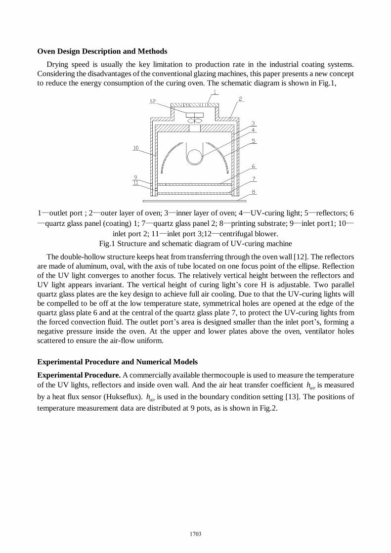
Oven Design Description and Methods Drying speed is usually the key limitation to production rate in the industrial coating systems.
Considering the disadvantages of the conventional glazing machines, this paper presents a new concept to reduce the energy consumption of the curing oven. The schematic diagram is shown in Fig.1,
1—outlet port ; 2—outer layer of oven; 3—inner layer of oven; 4—UV-curing light; 5—reflectors; 6—quartz glass panel (coating) 1; 7—quartz glass panel 2; 8—printing substrate; 9—inlet port1; 10—
inlet port 2; 11—inlet port 3;12—centrifugal blower. Fig.1 Structure and schematic diagram of UV-curing machine
The double-hollow structure keeps heat from transferring through the oven wall [12]. The reflectors are made of aluminum, oval, with the axis of tube located on one focus point of the ellipse. Reflection of the UV light converges to another focus. The relatively vertical height between the reflectors and UV light appears invariant. The vertical height of curing light’s core H is adjustable. Two parallel quartz glass plates are the key design to achieve full air cooling. Due to that the UV-curing lights will be compelled to be off at the low temperature state, symmetrical holes are opened at the edge of the quartz glass plate 6 and at the central of the quartz glass plate 7, to protect the UV-curing lights from the forced convection fluid. The outlet port’s area is designed smaller than the inlet port’s, forming a negative pressure inside the oven. At the upper and lower plates above the oven, ventilator holes scattered to ensure the air-flow uniform.
Experimental Procedure and Numerical Models
Experimental Procedure. A commercially available thermocouple is used to measure the temperature of the UV lights, reflectors and inside oven wall. And the air heat transfer coefficient airh is measured by a heat flux sensor (Hukseflux). airh is used in the boundary condition setting [13]. The positions of temperature measurement data are distributed at 9 pots, as is shown in Fig.2.
1703

(1)Inside oven wall
(2)Reflectors surface
(3)UV light
Fig.2 Positions of temperature measurement data in the curing oven
Simulation. At the operating state, the heat losing of the oven caused by radiation and natural convection accounts for about 10% of the total thermal dissipation, can be ignored. The forced convection air cooling and lights’ heat radiation are focused as the main subject [14]. Analysis of the temperature field and wind velocity field contributes to optimize the design of the area of outlet and other structural parameters. Geometry. The oven is idealized as the 0.12*0.12*1.00(m) cuboid modeling with the double hollow structure. And the oven is idealized as the cylindrical pipe and elliptical reflector. Meshing. Heat part consists of Hex/Wedge units (mainly composed of hexahedral composition, individual position allows a wedge-shaped body), and the other parts are mixed-meshing Tetra / Mixed units (mainly composed of tetrahedron and hexahedron composed between tetrahedron and hexahedron is pentahedron) [15]. The amount of division elements was 669 181. The boundaries of the domain of the CFD model are also depicted in the same figure. Check grid: No negative volumes found. The minimum of determinant is 0.21: Grid is available. A typical CFD model with the body positioned in a zone of the oven is shown in Fig 3.
Fig. 3 The CFD model domain of curing oven
Governing equation. The air-fluid’s motion state is comparatively complex. It can be assumed as incompressible unsteady turbulent fluid. The gravity is taken into account. The Re of the oven’s
1704

internal air-fluid is comparatively high, so the laminar flow phenomena generated by the nearly parietal is ignored. “Standard k ε− ” is selected as the fluid model. The model is described as follows,
[( ) ] ;tk b M
K
K w K G G Yµρ µ ρε
σ⋅ ⋅∇ = ∇ + ∇ + + − − (1)
( )2
1 3 2 .tk bw C G C G C
K Kε ε εε
µ ε ερ ε µ ε ρ
σ
⋅ ⋅∇ = ∇ + ∇ + + −
(2)
where ρ is density, K is turbulent kinetic energy; w is velocity vector; µ is dynamic viscosity; tµ is turbulent viscosity; kσ is turbulent Prandtl number for turbulent kinetic energy; kG is generation of turbulence kinetic energy due to mean velocity gradients; bG is generation of turbulence kinetic energy
due to buoyancy; ε is turbulent dissipation rate. MY is fluctuating dilatation dissipation; εσ is turbulent Prandtl number for turbulent dissipation rate; 1C ε , 2C ε , 3C ε are empirical constants in transport equation for turbulent dissipation rate [16-17].
The main mood of thermal transmission in the oven is the joint action of forced air convection heat transferring and heat radiation of UV-curing lights. The first two modes of heat transfer are described by a steady state Fourier–Kirchhoff equation,
( ) .vk T q cw tρ∇ ∇ + = ⋅∇ (3)
where k is thermal conductivity; T is temperature; vq is volumetric heat source; c is specific heat. The governing equation of convection is simplified to,
.PP P P
dThA T M Cdt
∆ = (4)
The radiation energy emitted by the UV lights consists 50% of the total power. Discrete Ordinates (DO) model is selected. Following the Stefan–Boltzmann law, the governing equation is described as,
( )41 2 ;rq T Tσε= − (5)
1 2
1 11 1 .εε ε
= + −
(6)
where σ denotes the Stefan–Boltzmann constant, equal to 8 2 45.67 10 W m K− − −× ⋅ ⋅ ; 1ε and 2ε denote the emissivity of the surface inside the oven and the UV lights. Boundary conditions. Without loss of generality, assumptions can be made as follows: Set a constant temperature of the outer layer of oven as 50. Few of steam are produced with the curing process. The air in the oven can be treated as dry air. The related parameters can be looked up at the physical parameters table.
The parameters of boundary condition settings are listed at the table 1,
1705

Table 1 Parameters of boundary conditions and setting Parameters Value Constant temperature of the oven’s outer layer [ K] 323
Convective heat transfer coefficient of air-flow[ 2( )W m K⋅ ] 20
Heat capacity of air-flow [ ( )J kg K⋅ ] 1006.43 Density of air-flow[ 3kg m ] 1.2 Thermal conductivity of air-flow / ( )W m K⋅ 1.5 Heat capacity of coating of coating glass [ ( )J kg K⋅ ] 745 Absorption coefficient of glass[1 m ] 831 Thermal conductivity of glass [ ( )W m K⋅ ] 1.38 Thermal conductivity of Hg[ ( )W m K⋅ ] 20 Heat flux of UV-curing lights [ 2W m ] 3316326 Heat transfer coefficient of reflectors[ 2( )W m K⋅ ] 7 Internal emissivity of reflectors 0.2 Diffuse fraction of reflectors 0.3 Velocity of inlet port[m/s] 1
Results and Discussion
CFD post-processing. The convergence rule is 0.001. After the calculation of 200 iterations, the system tends to a stable state. Solution is completed. CFD-Post is conducted to analyze temperature field distribution of surface getting through the middle of the oven’s side face and perpendicular to the lights’ axis, as is shown in Fig. 4.
Fig.4 Temperature distribution contour of UV-curing oven under different wind velocity: 0.5, 1.0,
2.0 (m/s).
Referring to Fig.2, pot 2, 5, 8 are chosen as the monitor points. Under the different wind velocity conditions, the temperature of the points is simulated. Judging from previous experience,the wind velocity is chosen as 1 m/s. The temperature distributions are separately shown in Fig. 5.
Comparison of temperatures between the real data and simulation data has been conducted for 9 pots during the stable state time. As is shown in Fig. 6,
1706

Fig.5 Temperature of pot 2,pot 6 and pot 8 under different wind velocity conditions: 0.5, 1.0, 2.0,
3.0[m/s]
Fig.6 Comparison of temperatures between the real data and simulation data has been conducted for
9 pots
The temperatures predicted by the CFD models are higher than the real air temperatures. This is due to the ignorance of the thermal radiation transmission of oven wall towards external environment and the fast movement of printing substrate. The maximum deviation is in the range of 1.3~2.9%.
In spite of the slight gap existing between them, the conclusion can be made: This CFD model gives an accurate prediction for the temperature distribution of the oven. Application on glazing machines. Glazing machine mainly consists of four parts including the paper feeding part, oiling and imprinting part, UV-curing part and paper collecting part, as is shown in Fig. 7. Due to the introduction of new UV-curing equipment, the whole glazing machine turns to be more efficient and energy-saving. The maximum production speed is 9800 sheets / h.
Fig.7 Structure and actual diagram of high-speed UV-coating machine
Energy efficiency analysis. 3 types of glazing machines are selected as follows: thermal infrared glazing machine(type A), UV-curing and water cooling type (type B)and high-speed and full air cooling type with optimal energy-saving design(type C). The governing equation of the energy consumption is described as,
.C PES
⋅=
∑ (7)
where C denotes the standard coal coefficient of electric power conversion, equal to 0.404; P denotes the total power; denotes the pressing area per hour.
1707

The related parameters and energy consumption of them are shown in Table 2.
Table.2 Energy consumption per unit of coating machine with different models Machine Type A B C Drying Method infrared UV UV Cooling Method full water water + air full air Width [mm] 1200 1000 1060 Speed [m/s] 1.17 1.10 2.07 Light Power [kW] 15*2 3*8 3*13 Output Power [kW] 44 28 45 Total Power Consumption [ kgce h ] 5.405 3.440 5.528 Energy Specific [ 2gce m ] 1.540 0.914 0.787
The unit of energy consumptions is converted into 2gce m (standard coal consumption per square meter) [18].
Summary (1) Based on the CFD techniques, this paper proposes an optimum energy-saving design of the
novel full air cooling UV-curing oven with advantages of high efficiency, low energy consumption and compact structure. The glazing machine equipped with this oven achieves the speed of 9800 sheets/ h.
(2) The temperature field inside the oven is simulated by Fluent. The maximum simulation deviation is in the range of 1.3~2.9%. The deviation indicates that the CFD model had an accurate prediction.
(3) Due to that either the temperature inside the oven is too high or too low jeopardizes the pressing’s quality, the optimum wind velocity of the inlet is chosen as 1 m/s. The combination of measurement and simulation contributes to accelerate development cycles and to put forward a general convenient oven design method.
(4) Table 2 indicates that, compared with the infrared drying glazing machine, the novel full air cooling UV-curing glazing machine is significantly more energy-efficient. The type C average effective power consumption per unit decreases about 14.0% compared to type B, and decreases about 48.9% compared to type A.
References
[1] Yang K, Optimization of UV Curing Equipment and Process Parameters, D. Shanghai Jiao Tong University, Shanghai, 2009, pp. 2-5.
[2] Zhu S W, Shi W F, Study on UV Curing Equipment and UV Curable Materials, J. Photographic Science and Photochemistry. 19 (2001) 295-296.
[3] Han F J, Liu J F, Design of Comprehensive Paper Dryer Path, J. Packaging Engineering. 9 (2008) 100-101.
[4] Zhang G R, Liu Y, The UV-curing Printing Technology with Application, Chemical Industry Press, Beijing, 2006.
[5] Song B, Tang Z N, Parameter Analysis of Droplet Ejection of Piezoelectric Ink-jet Printing, J. Packaging Engineering. 32 (2011) 93-96.
[6] Preetham P, Rao, Ashok Gopinath, Energy Savings in Automotive Paint Ovens: A New Concept of Shroud on the Carriers, J. Sci. Journal of Manufacturing Science and Engineering. 135 (2013) 2-6.
[7] Huang Q M, Chen F Y, Xu P, et al, Study of the Energy-saving and Emission Reduction of Intaglio Press Drying System, J. Packaging Engineering. 31 (2010) 25-26.
1708

[8] Huang Q M, Xu P, Bao N S, et al, Energy-saving & Emission Reduction Technological Control Research of Drying System to Gravure Press, J. Light Industry Machinery. 27 (2009) 98.
[9] Huang C K and Song J G, The application of UV-LEDs to microlithography, C. Second International Conference on Integration and Commercialization of Micro and Nano-systems in Hong Kong, New York, 2008, pp. 82.
[10] Zinedine K, Joe P, Harvey T, et al, Optimization of the energy efficiency of bread-baking ovens using a combined experimental and computational approach, J. Sci. Applied Energy. 112 (2013) 919-920.
[11] Sathit N, Paisan K, Ajaree S, et al, Enhancement of energy efficiency in a paint curing oven via CFD approach: Case study in an air-conditioning plant, J. Sci. Applied Energy. 156 (2015) 469-470.
[12] Chen J Y, Guo X M, China. Patent 201420856213.X. (2014)
[13] Balazs I, Distribution of the heat transfer coefficient in convection reflow oven, J. Sci. Applied Thermal Engineering. 30 (2010) 1528-1530.
[14] Wen Z, Shi L C, Ren Y R, Fluent: Tutorial for the application of CFD, Tsinghuag University Press, Beijing, 2009, pp. 232-245.
[15] Jecek S, Andraej J. N, Dawid R, Improved 3-D temperature uniformity in a laboratory drying oven based on experimentally validated CFD computations, J. Sci. Journal of Food Engineering. 3 (2010) 374, 378.
[16] Anderson. J D, Computational Fluid Dynamics: The Basics with Applications, McGraw-Hill Press, New York, 1995.
[17] Zhang R X, Sun L P, Application on Airflow Detection of Wood Drying Kiln Based on Computational Fluid Dynamics, J. Development & Innovation of Machinery & Electrical Products. 1 (2010) 120.
[18] Jin L, Li Y, Wang Y M, et al, Energy Efficiency Analysis of Gravure Press Based on Energy Consumption Test, J. Packaging Engineering. 35 (2014) 120-123.
1709