research ‘m~orandum - digital library/67531/metadc64197/m2/1/high... · angle between span ax36...
TRANSCRIPT

RESEARCH ‘M~ORANDUM
. - TslnalnY
I AERONAU TICS
-4 6
I
I f
.-
Restriction/Classification Cancelled
Restriction/Classification Cancelled

b :
f
a .
Spin t e s t e of a &-scale model of the Chance .Taught XF-1 airplane have been performed in the Langley 2CLfoot free-8pinniIq tunnel. The effect of control posftion and mapemen t upon the erect and inverted spin and recovery characteristics ae well as the effects of propellers, of stability flaps, and of various revisions to the design configuration have been determined for the normal fighter loading. The investigation also included spi~recovery-parachuta, tumbling, and pilot-escape t e s t e .
/-
For t h e original design confJguration, with or without windmilling propellers, the. recovery chq-acterletics of the model were considgr'ed unsatisfactory. hcreasiethe maximum upward deflection of the ailavators f'rom 45' to 65O resulted in greatly improved recovery characteristica.
Dimensional revisions to the ariginal airplane configuration, which satisfactorily improved the general spin and recovery characteristics of, the model, consisted of: (1) a su?plementary vertical t a i l 34 inches by 59 inches (fun-scale) attached to a boom 80 inches aft of the trailing edge of the airplane i n the plane of symmetry, (2) a large semispan Und- surface spoiler placed along the airplane puarte-chord line and opened an the outboard side in a spin, or (3) two additional vertical tall8 64 inches by 52 inches (full"sc&Le) located at the tips of the silavatore.
A satisfactory parachute arrangement for emergency spin recovery from demonstration epins w a ~ found to be an emmgement consisting of a 13.3-f'OOt parachute attached by a 30-foot towline t o the arresting gem mast on the airplane and opened simultaneously with an &foot pazachute on the outboard end of the w i n g attached by a 3foot towline. Tests indicated that pilot escape.flram a spin would be extremely hazardous unless the pilot is mechanically ejected f'rom the cockpit.
Moael tumbling t e s t s indicated that the airplane would'not tumble.
UNCLASSIFtED Restriction/Classification Cancelled

2 " mcA RM No. L7I23
llpTROUCTION Z '
Spin tests have been performed on a -- scale mdel .of the chance 16
Vought XF'Wl airplane- in the Langley 20-foot free-spinning tunnel as requested by the Bureau of Aeronautics, Navy Department. This airplane which is a singlc+place twbtail flying-wing fighter has an almost circular planform and is equipped with large twin propellers, one mounted at each wing t i p . I;ongitudinal and lateral control are combined in alldnovable horizontal tails ham as "ailavators ."
A" scale model of the prototype of the subject airplane deeigna.ted: 16
the V o u g h M i k o r s Q V-173 had previously been t e s t e d in the Langley 1 5 f o o t freespinning tunnel (reference 1). me airplane is different from the V-173 airplane previously tested in weight and in design of .the horizontal tails.
The current program included tests simulating only the n o m fighter loading of the XF5U-1 amlase. It was f e l t that the effect of variations in w i n g loading and maments of inertia on the spin and recovery char- acteristics of this design.could be aetermined from the test results pre- sented. in reference 1 for the prototype airplane.
Erect and inverted spins were performed to determine the effect of masrim and intermediate conk01 settinge on thespin and recovery c e acteristics of the mOael, lancling gear retracted, Additionhl tests were made to evaluate the effect on spin and recovery characteristics of vasious dimensional revisions to the model configuration,.as well &e the effect of the propellers and the stability flaps, and a l s o to determine the parachute requirements for emergency recovery f'rora demonstration spins. Tumbling and pilo&escape teste completed the program.
b
S - C
C
wing span, feet
wing axe&, square feet
man aerodynamic chord, fnches
root chord (chord of airfoil section at plane of symmetry), inches
ratio of distance of-ceLter of gmvity rearward of leading edge of man aerodynamic chord t o mean aeroQmmic chord
t
. -

mCA RM qo. L7I23 1. 3
t Z / F ratio of distance between center of Savity and
. thruet line to man aerodpam€c chord (positive when canter of gravity i6 below thrust line)
rn ' mass of airplane, d u g s
IZ -5 mb 2
P
P
Al
A2
inertia pitching-momnt parameter

t l 4 .
t a
i
B V
a
d
B
- NACA m NO. ~7123
angle between thru6t line and vertical (approximately equal to absolute angle of attack at plane of symmetry), degrees
angle between span ax36 and horizontal, degree6
full-scale true rate of descent, feet per second
full-male angular velocity about spin axis, revolutions per second
helix angle, angle between flight path and vert ical (for t h l s m o d e l , the average absolute value of ‘ the helix angle w a 8 approximately lo), degrees
app&.mate angle of eideslip at center of gravity, (sideslip ie inwaxd when inner w i n g it3 down by an amount seater than the helix angle), degrees
Model
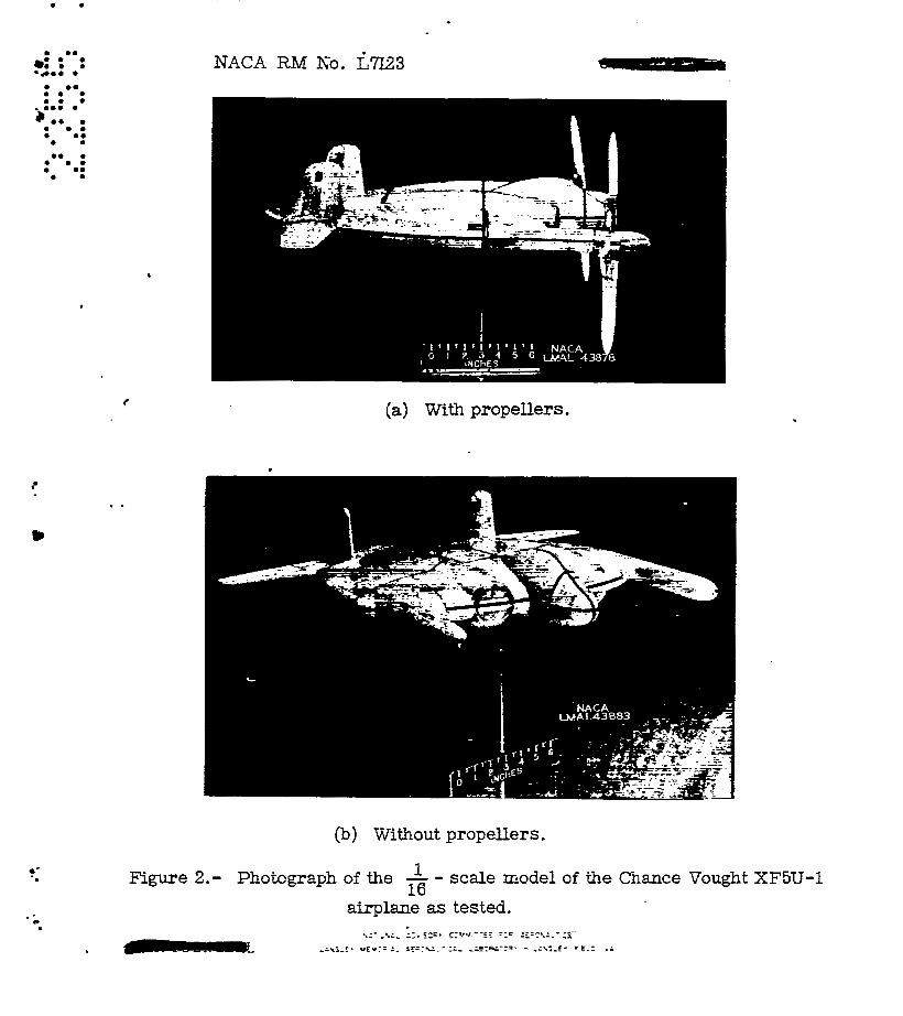
The ” scale model of the Chance Vought XF-1 airplane was furnished - 16 by the Bureau of Aeronautics, N a V Department, It wae checked for dime* sional accuracy and mepared for testlng at t he Lane;ley Laboratory. The model comlete with propellers is represented in the tbe+view drawing , . of figure 1 and photographs of ‘the m o d e l 88 teated, with and without pro- pel&rs, are sham In figure 2. The respective dimensional character- istics of the XF-1 and the V-173 airplanes ere listed in table I and graphically compared in figure 3 .
The propellers weme interconnected and rotated in opposite directions, rotation being upwaxd in the center. Each propeller hud four blades, and each set of two opposite blades waa constructed t o allow a lon$itudinal flapping motion of 210~ as a unjt. The d e l propellers were mawed to w i n d m i l l during the p r o p e l l e m testa. During the propellals-off t es t s , the propeller aesembliee were replaced x i th a dumy hub without bMet3.
!Fhe model and popeller assemblies were ballaeted by mans of lead weights to obtain dynamic similarity to the full-scale &plane at an altitude of 15,OOO feet ( 6 = 0.001496 sTug/cu ft). Interchangeability between the propeller assemblies and the set of d m hubs was afforded by ballasting the d m hubs to simulate the might dietribution of the

-? c
a
t
RACA RM mo. ~7123 - 3
The leading .edge of each fin w88 offaet 2O outboard '09- the model , * '
center line t o confarm to the full-scale vertical-tail conffguration.
Wind Tunnel and Testing Technique
me tests.were performed in the Langley 2Cbfoot f'ree+spinning tunnel which is similar i n opratim t o the Iangley 1Wmt f 'rewpinning tunnel described in reference 2, except that the model-launching technique haa been changed. Wfth the control8 set in the desired positions, the model . f a hand-launched Kith.rotation into the vertically rising air stream. After a nmte r of turns in t he established epin, recovery is attempted by moving one or m o r e control6 by means of the remotHontrol mechanlem. Upon recovering from a spin, the model dives I n t o the safety net from Whence it ie retrieved. The spin data obtained from these teat8 &re then converted t o correeponding full-scale values by the methods deacribed in reference 2. Figure 4(a) 18 8 photograph of the m a i d , without progellers, f'reely spinning in the Iangley 2Sfoo t freespinning tunnel.
It became apparent after a few initial attempts to epin the model fkeely with the propellers installed that little progrese could be &e because of the frequency with which the model progellers became damged when the model landed i n the safety net. To erpedite the testing with propeller inetalled, an apparatus m8 devised t o support the &el in the tunnel. Thie apparatus cansisted of a nylon line attached at one end t o the top net in the tunnel from whence it passed through a fixed s t e e l ring 10 inches in diameter. The other end x88 attached t o a universal joint (fig. 5 ) Imated on the upper surface of the model above the center of s a v i t y t o a l l o w the model freedcan of mtion about t h e e axes. The s t e e l ring res t r ic ted laterdl. mtfm of the model, weventing c m k c t with the' tunnel W.
When the &pension appasatua was being used, the technique differed f r o m t h a t deacrlbed previously for the f'ree-spinnfng t es te only in that it ellminated.the hand leunching. The model, mspendgd in the middle of

5 EACA RM NO. ~7123 Y k "
ir
i
the tllnnel ark the end of' the nylon l h e , was gently pushed by means OP a long pole t o 'a l t ikte its rotation. The tunnel airapeed was then increased untI1 t he spinning motion &e established. Figure h(b) s h m the mcdel, propellers Installed, spinning on this apparatus.
In accordance with standard epin-tunnel mkhcds, t ee t s were performed -
t o determ'lne the sD:n and recovery characteristics of the model for the nord-control configuration for spinning (st ick longitudinally back and laterally neutral, rudder fu l l with the spin) and for various other neutral, intermediate, and maxim long'rtudinal and lateral s t i ck
* positiona. Recovery fsrom these spfm was generally attempted*by rapid reversal of the rudders from full with t o full agaimt the spin. Tests were also performsd t o obtafn the spin and recovery characteristics of the model for w h a t is referred to as the "criterion spin" to evaluate the possible adverse effects of small control depiations f r a m the nmmal- control configwation'far spinning. Far theee tests, the ailavatore were
f u l l back in conJunction w5th the lateral positions of both one-thlrd with and onethird against the apin ( s t ick right in right spin and s t i ck l e f t in r;ght spin). For this model , lateral stick settings of both with and against were used because it wae not readily apparrent wmch direct ion w a r l d be adverse. Recovery from this' , the criterion spin, was attempted by rapidly reversing the rudders from full xith t o only twcAhir&s again& the spin.
Bet at a po8ftiOn Si&tin& that exist- W h e n the stick 18 tw-thfrds
The turns for recovery were msaaured f'rom the tima the controls were moved or -the parachute opened t o the time the ssin rotat ion ceased. The recovery characteristics of a model are considered satisfactory i f recovery from the c r i te r im sp in requi res no mare than i\t t u r n e .
For recovery attempts in which the model struck the safety net before recovery could be effected, because of the wandering or osci l la tory nature of the s p i n or beceuse of an unusually high rate of descent, the number of turns from the time the controls were moved to the time the model struck the safety net were recorded. Thie number Indicates that the model required more turns t o recover.from the spin than shown a4 f o r example, >3. A >*turn recovery, however, doee not necessarily indlcate an im?rovement mer 8 >7-turn recovery. The spibol 03 is used on the charts to indicate that recovery required more tlgn 10 turns. For a condition in which the model recovered w'lthmt movement of the controls after ,having been launched in a spinning attitude with the con5rols set
a fo r a spin, the result is recarded on the chaste 88 "no spin. 'I
The testing technique for dste-rlaining the opt.lrmlm size of and towline length for spierecapery parachutes is deacribed in reference 3.
.

NACA RM NO. ~7123 - 7
For the present tests, the m o d e l wa8 launched into the tunnel with the rudders aet full with the spin. In general, the steady-apin control settings were maintained, recovery being attempted by the action of one tail prachute or a combination of tail- and “tip parachutes, but f a r several tests, the ailavatore were moved and a tail parachute opened eimultaneously. The several parachute-attachment locations tested on the model included one suggested by the contractor. The two most prae tical and therefore moat thoroughly investigated consisted of: (1) a tail pezachute attached to the mesting gear nmst (that suggeeted by contractor, fig. 6 ) ; and (2) a combination including (1) ami a parachute attached to the outboard end of the w l n g at the quarte-hord line. Tbe parachutes were installed, while packed, on the upper surface of the model near their attachraent locations and in euch a maMer BB not to affect the steady apin until opened. It l e recammellded, however, that for full-scale parachute installations the parachute8 be packed within the airplane structure with provieion for positive ejection. The para,- chutes used for the model tests were of the flas circular type. The drag coefficient based on the lafd-out flat area was appraxlmately 0.7.
To determine the susceptibility of the m o d e l to tumbling, two methods of launching the m o d e l were employed. It wae either releaeed f r o m a nos-p poeltlon to simulate a whip stall or W ~ B given an.initial pitching rotation about a lateral axis. The resulting motion was recorded by mane of a camera. Tf a moder can not be made to tumble by either of the two launching method8 described above, it I s considered i ncapab le . of tumbl. 1 ng .
-
For the D.ilot-escare tests, the dummy pilot wa8 released f r o m the jn3oard slde (right side in a right min) and the outboard slde of the model at the cockpit when the model was in typical flat and typical steep spins.
-

'p cr
c
I
8
The preceding limits may ham been exceeded for certain spins in which it wa.8 difficult t o control the model in t h e tunnel because of the high rate of deecent or because of the wandering QF oacilLatory nature of the spin.
Comparison between spin result8 of airplanes and t he i r repreqentative scale modela (references 2 and 4) fndicatee that spir+tunnel r e d t s are not always in complete agreement xith the results of Rzll-scale spinning. In general, the models spin a8 somewhet smaller angles of attack with higher rates of descent and 5 to loo m o r e outward sideslip than their full-scale counterparts. The comparison mads in reference 4 ehowed that 80 uercent of the madel recovery tests predicteicd satiefactorily the number of turns requirsd for recovery from the corresponding airplane8 while. 10 Dercent underestimated and 10 percent overestimated the number of turns required.
The results of tests made on the suspension apparatus 8.m of' questfon- able exactness and are not published in detail In this pager. These results 81'8 considered of only qualitative value and are 80 discusaed here in
Because of the Fmpracticability of exact ballasting of the d e l and because of inadvertent d a m g n t o the model d u r i n g the tests, the measured weight and mass distribution of the model varies frm the true ecded- down mlues by the f o l l m i n g amounts :
Weight, percent, . . . . . . . . . . . . . . . . . . . . . . . 0 to 3 high Centemf-gravity location, percent S . . . . . . . . . . 0 to 1 rearward 5, percent . . . . . . . . . . . . . . . . . . . . . . . 4 l w t o 4 . h 1 g h IZ,percent ............................ 3 h i g h
T,perceat ......................... 2 t o 3 h i g h
The accuracy of measuring the w e i g h t and mas8 distribution is believed to-be withln the i"0llowing I-lmlts:
Weight,perce~t........................... Centemf-gravity location, percent Z . . . . . . . . . . . . . . . . writs of inertia, percent . . . . . . . . . . . . . . . . . . . . . k5
The controls were set with an accuracy of Ll, . 0
i

9
A8 msntioned earlier, apfn tests of the L-8cale model of the 16 XF5zF-1 airplane were lFmited to those fm 8 s f t i o n of the normal fighter loading. The -8 ch&rachristics and inertia paramstere fo r the n d loading, and for other .possible loading8 of the aJrglane, and for the loading a8 8ImhRted on the d e l (carrverbd to f’ull-acale &uee) are given in table 11. The inertia parameters far the p ~ ~ i b l e loadings of the XF-1 airplane and far the loading0 teated on the m5-l airplane and V-173 models are plotted in figure 7.
The normal. mlrmrm control deflections fm the model were obtained Frm information f‘um58hed by chaace Vought. AB previously indicated, the rolling and pitching cont$ols are ccpnbined in one surface called 811 ailavatar. The mrml angular deflections m e given in figure 8 which indicated that for pure longitudinal stick travel From fill bagk to fill
’ farwasd the carreeponding m a x i m u m ailavator deflectlone are 45 up and 15’ dam. Displacing the stick laterally affects the ailmmtor setting differentially, thereby creating effective- an aileron setting. Maximum lateral displacement of the stick causes, in this manner, a surface incidence differential of k l O o or, in other wmd8, with the stick in p of the t w o meximum lateral-positions, a t o t a l incidence difference of 20 exists between the respective chord lines of the left and right ailavators. When the stick-is moved forward or backward while in this lateral polsition the elevator setting only fe affected, the total angules differential of 20° being mlntained. The rudders were deflected n o m m ~ ~ ~ f25O.
All lateral and longitudinal control deflections will be given in this paper in the.form of st lck Dositfon which when referred to figure 8 may be t r m ~ p o ~ e d to give the sctual setting of each ailavator.
Intermediate control positions tested were a8 follare:
Stick laterally on-half agalmt the.8Din
Stick laterally anwthird with the spin OT on+third agaimt the Ispin
Stlck laterally on-fourth against the spin
Stick longitudinalfy tw+thirda back ,
Rudders deflected tw-thirds @ O )
A series of tests were also performd far two upelevator settinge exceeding tHe design lllaxlh u p e l e v a t o r deflections of 45O. These two settings were 65O and 85O. For these teats, it wae aesumsd that gull lateral, stick movement caused the 8 m differential change of 210 that

f
occurred with normal stick-back deflection. The two corresponding Inte- mediate stick-beck positions (stick.longitudidly tw-thirds back) tested for the criterSon-spin control configuration used w l t h each of the t w o mcd5fiad' maxim deflections were 4$ (for 65 1 gzld 9 (for, 85O) 0 0 0
3 The &ability flap deflection tested w a s 25O, the angle of flap
deflection being measured between the thrust center line and the flap chord line.
Fow propeller pitch angles measured at 0.75 radiua of the blade were used and included 100, 30°, Goo, and 90'. For these t e s t s the propellers were allowed to windmill.
For all the t e s t s reported herein, the landing gear was retracted, as was previously mentioned, and the cockpit x a ~ cloeed.
Results of tests made with the model f reely spinning are presented -in terms of full-scale values far the airplane at an altitude of 15,OOO feet in charts 1 to 4 and in tables IU: to V. Inarsmuch ae the initial tests of the model without propellers yielded similar results for both right and left erect spins, most of the t e a t s were arbitrarily performed with the model epinning only to the right.
The results of left and right erect splne with the model in the normal fighter loading, landing gear retracted .(condition 1 on table I1 and fig. ?),are presented in chart 1. With the controle set for the n"conkro1 configuration for s p f d n g (stick back and laterelly neutral, rudder fill with the spin), two conditions appeared to be pes i - ble; one cond5tion a "no spin" and the other condition a epin w i t h a astlsfactory recoverr. The tendency for the spinnlng condition to per- sist was indzcated, hawever, as slight control deviations from the normal- control confjguretion (crjterio-pin settings) caused two t y p e of spin, and recovery could not be obtained by rudder reversal from the flatter saln. Slmj.larly, poor recoveries were obtained from apins in which flat attitudes and extreme wanderfng motions were cheracteristic when the stick was laterally against the spin and either neutral or forward longitudi- nally. The ruddere were ineffectsve in epim at-these las-ntioned
4 ' c

f control configurations and the model. continued' to spin follo;King rudder reversal. Unsatisfactory Bpi-recovery characteristics were ale0 indicated when the stick was longitudinally back and laterally with the spin. The opt- control positions appeared to be stick longitudinally full back and laterelly full againert the spin (conditim for "no spin"), or stick 1ongi~udind.Q full fo-d and laterally with the spin. Recoverfee atteupted by simultaneous reversal of both rudders and movenaent of the stick full-back and laterally 4'ull w i n e % the spin, h m v ~ r , were not considered satisfactory because of the time required following the control movement f o r the model t o go frm the flat epinning attitude t o the steep attitude of the n-pin condition ( W t 1).
As noted previously, it -8 found that a ~o-spin condition persisted when the stick was full beck and laterally fill against the spin, but that when the stick'xas laterally full xi th the spin, no recovery could be obtained for this stick-back position. Beteed on these reeults it apseaxed thst the outbo-zrd ailavator ( l e f t ailavator in a right epin) had to have a minimum upward deflection of 55O to produce the n-pin conditim obtained for the previoudy mentioned optimum control poaltion fn which the stick was fill back and laterally fill against the spin. In order to improve the spiprecovery characteriet.ics of all spins vith full-bagk stick, the m a x f m u m longitudinal control setting was .Increased to 65 up w i t h a resultant mZnlmm upward deflection of the gutboard ailavator far any lateral etick Dosition (etick fu&l back) of 55 . The respective u p ailavator deflections then became 55 and no at either one of the t w o maxjmum lateral stfck positions when the stick vas h e l d f u l l back. A second revised maxjnnun longjtudinal control deflection teated gave ailavator deflections of 75O and 950 at either of the two maximum lateral stick posftions. The results of them test8 are given in table =I. It is apparent that these larger longitudinal control deflections were decidedly beneficial, resulting in n-spin conditions for the stick-back control configuration.
a k
3 ,
With the ailavators completely removed, it was found that the model would nat spin.
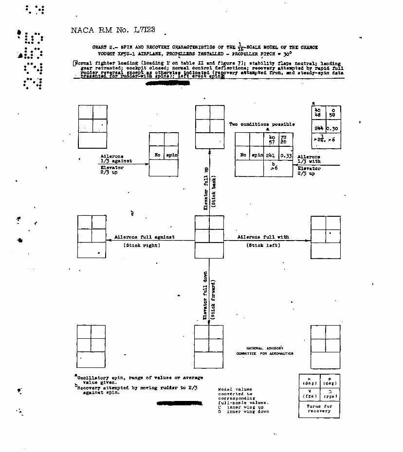
Using the enrspensian apparatus previously described, spin tes ts were cerrl.ea out to determine the effect of w i n d m L l l i n g propellers on the apin and recovery characterletics of the model and to select the optimum propellez-blade pitch angle. Cmparieon of results obtained far the four- blade angles of 100, 30°, 600, and 90° s?~med that 30° x88 the optimum
vi th

NACA RM No. L7123
the nroxllers set at a-pitch of 30 . The resu&te of these teats, wh€ch a r e nresented in chart 2, reveal that the characteristically flat spln R-om which recovery I s unsatisfactory stlll exists, the epins and recoveries, in general, being very similar to those obtained without nropellers. It seems, therefore, that no appreciable improvement in the recovery characteristics can be expected from windmilling propellere in a' apin of this airplane.
0
Inverted Spina
The results of inverted spin tests performed for three control co+ figurations on the model, propellers remwed, a d with the model rotating to the pilot's right are given Fh chart 3. The order used for presenting the data for inverted splns is different f'ram that wed for erect spins. Far inverted spina, control8 croeeed for the eatabliehed spin'(right rudder pedal forward and stick to pilotre l e f t for a spin to pilot's r igh t ) is presented to the right of the chart and etick longitudinally forward at the top of the chart. When the control8 m e crossed in the established inverted spin, the ailawtors aid the rolling motion; when the contro'ls are together, the ailavatora oppoee the ro l l ing motion. The angle of wlng tilt _$ on the chart is given as up or d a m relative to the
8 I
Round. . . - " .. - - . .
Spinning in an inverted attitude, the m o d e l demonatrated a epinniw motion similar to that exhibited for the erect spincr far the control cor+ figurations test-ea, Recoveries from these inverted apim were a l e 0 poor as sham in chart 3, Based on the model epin tesh the inverted spirr- recovery characteristics of the airplane bl'e expected to bs unsatigfactory.
Q .
Recormnende& Recwery Technique
It fa advised that the airplane in its present deaign configuration he prohibited from any fntentional spirznlng; however, in case of Inadverc- tent syfns, the following control technique for recovery is recommended:
Erect t3~im.- The stick musk be set and held full back and laterally full agajnst the spin before the rudder is reversed. Rudder reversal must be rapid and complete. Thia control configuration should then be main- tained until-the spinning rotatlon ha8 ceased.; the stick should then be nsutrali zed laterally and pushed forward of neutral longitudinally t o regain normal unatalled f l igh t . If after 'j turns-the rotation ha8 not stopped, hold rudder full w i n s t the spin and push the etick forward and

c
a L
EACA RM No. L7I23 13
lateralljr with the spin. When the e p l a n a has became unstalled, cere should be exercised to prohibit any excessive rates of acceleration which my be coincident with the ensuing dive.
Inverted 8DfnS.- To effect optimum recovery from imerted Spina, the stick should be moved Full forward and laterally in the same sense as the steady-spin rudder (controls together) immediately upon enterlng the epin; the rudder should then be reversed' brjskly to full against the-spin holding the stick at the prescrlbed position until recovery is obtained. Be. in the case of erect spine, if the airplane beco~ea unstalled, care should be taken.to prohibit any excessive rates of acceleration possibly colncident with the ensuing dive .
Dimen8iom.l Revieions to the Desi@. Configuration
The results of free-spinning tunnel tests =de OR the model with propellers removed for various dimeneional revisione designed t o Fmprove the recovery cbacterlstice of the model are presented in table IV. Drawings of the dimensional revisions tested 83'8 shown in figures 9 to 14.
c lnaamuch as it was recognized that any improvement to the epirr-
Q determine only the modifications necessaxy to prevent spins in the flat
k recovery charracterietica was dependent upon Che elhdnation of the . - cheracteristically flat spin, the pr- obJective of these tests waa to
attitude. AccordI~@y, most of the testa were perfarmed for N e t ORB control configuration, stick longitudinally neutral aml l a t e r a l l y against the spin, h o r n to c m i s t e n t l y produce the fla+type spin.
The results of tests of those revieione whlch had no effect on the flat spin m e given in section A, table IV. The results of tests of revisione whlch, although influencing the spin beneficially to some extent were not considered &B eatiefactory, are presented in section B. These revisions included such devices as slots on the leading edges of both ailavators, spoilers on the upper surfaces of both ailavatare, and longitudinal fences on the upper and lower surfaces of the airplane w i n g plan form proper. "
The results of tests bf revieiona that elizdnated the flat spin and satisfactorily improved the spin and recovery characteristics are pre-
* sented in section c of table IV. These revieions were: (1) a s u p p l e mentary vertical tail 34 inches by 59 inches (fU~-SCSb) located 80 inches remaid of the airplane trailing edge in the plane of symrcetry

a s 14 NACA 'FiM No. L7123
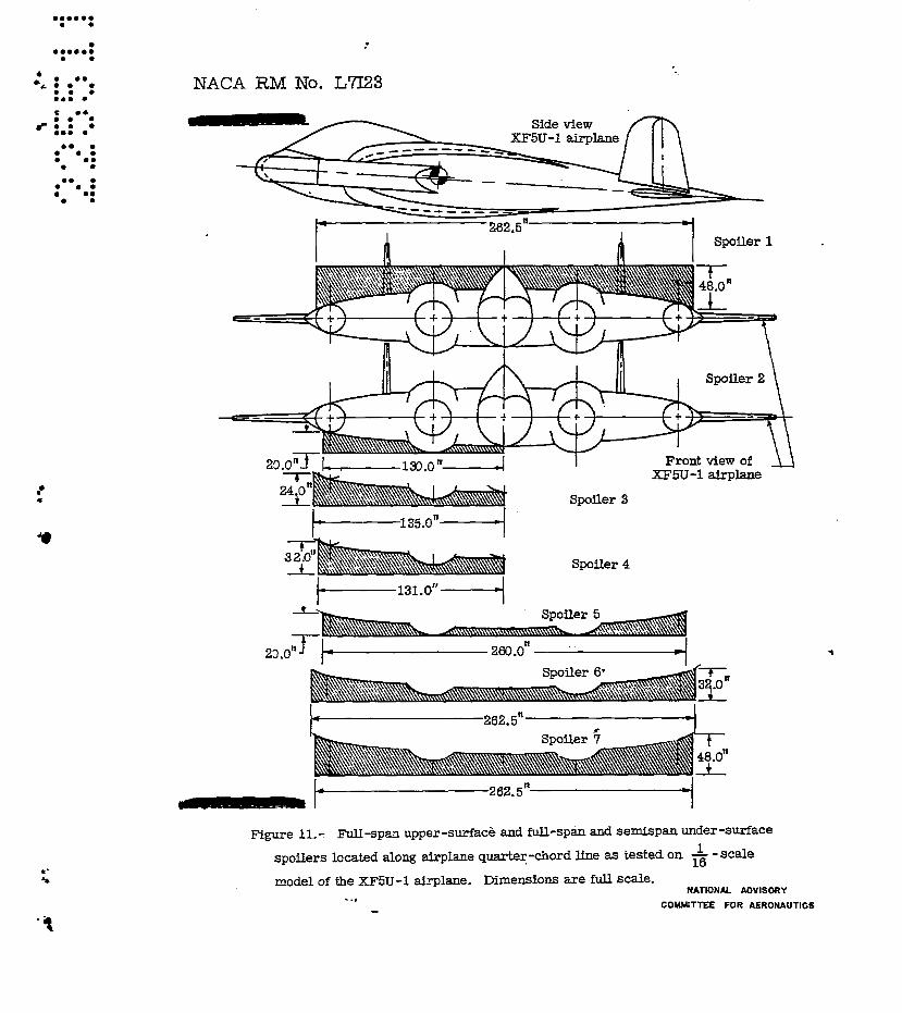
(supplementary tail 2, fig. 9 ) ; or (2) a large sedspan undersurface spoiler placed along the quarter chord and deflected d m a r d 90' t o the chord on the outboard side i n a s p i n ispoiler 4, fig. ll); or (3) two large vertical. fins 64 inches by 52 inches (full-scale) located a t the ailavator tips (vertical fin 7, f ig . 10). For this last revision, it was found that arbitrarfly fildng 16 inches of the reaxward parts of both vertical fins 200 against the spin, t o 8imLllat.e antispin rudders, produced a -in condition, the spin rotation dBmping aut rapidly (within 3 turns) after the launching (table IV). me -spin condition still prevailed whether these sfmulated rudders were set at neutral or 100 Kith the spin, but the number of turns required before the spinning rotation ceased was definitely greater (reaching 88 m c h 88 15 turrm) than those for the conditim in which the rudders were aet against the spin.
SpiwRecmery Ferachutes
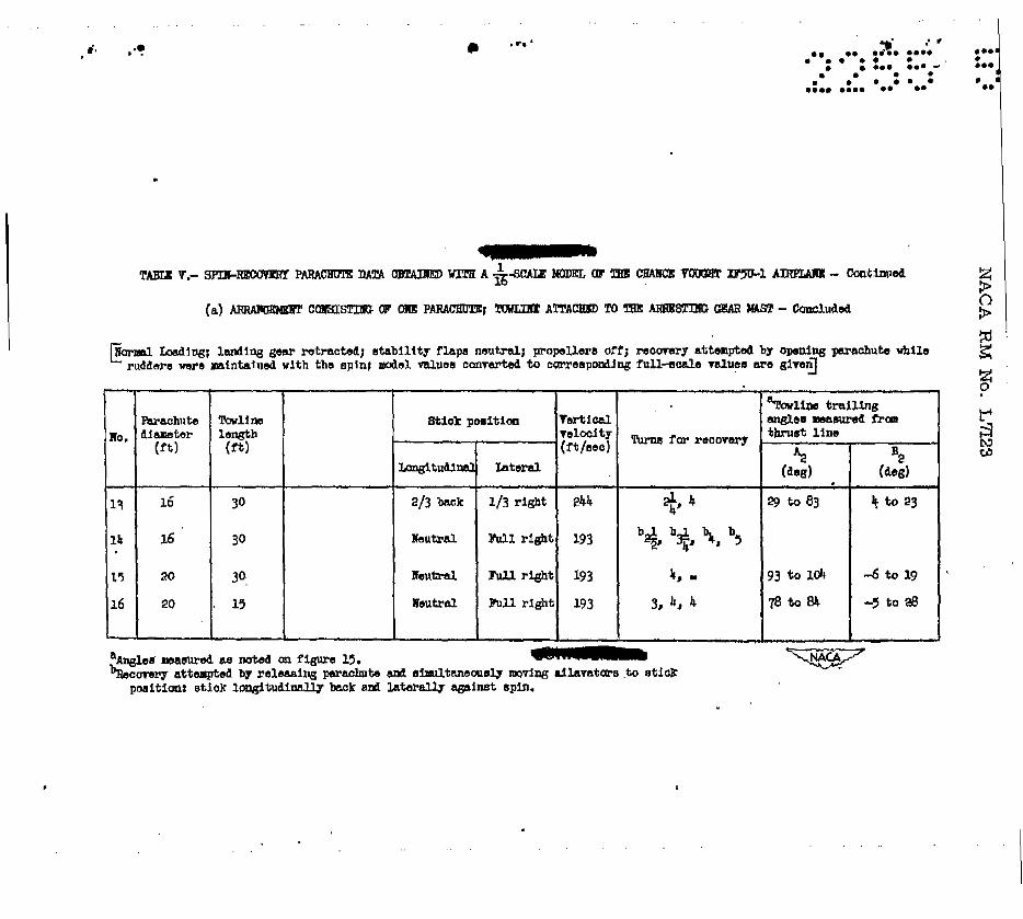
The results of-the spirr-recovery parachute tests, propellers off , are given in table V sections (a) and 'b) and the method used to define t h e towline angles i.8 s h ~ fn ffgure 15. The results presented in aec- tion (a) ere for one parachute attached t o the arresting gear maet. The reaults show that ,a l though narachutee as large as 16 and 20 feet in
flat criter'ion m l n (sttck longitudinally tQ0-thirds back and laterally either one-third with the spin or against the s ~ l n ) and for the flat sp in existent when t he stick is longitudinally neutral and laterally against the spin.
i
d-;ameter (full-scale) were used, poor recoveries were obtained from the
It was requested by the contractor that specific t e s t a be performed to, determlne the effect of o ~ e n l n g a tail parachute while simultaneously moving the sthk longitudinally back and laterally against the spin, a ccntrol configurption which had previously yielded a nwspin condition. The tests were W e using a lcfaot (full-scale) parachute attached to the arresting gear mast by a 3Gfoot (rn-scae) towline, The ailmators were set to represent a stick configuratlon of neutral longitudinally and agaimt the spin laterally, to produce a flat spin prior to t h e recovery attempt. The results of them tests which appear in table V section (a) indicate that reccvery cculd not be effected by this technlque within 2- turns. This recovery technlque therefore l a not expected to give satfsfactmy recovery on the airplane.
1
I' .

NACA RM No. L7I23 - 15
0
The results presented in siction (b) of table V indicate that u l3.3foot (full-scale) parachute attached by a 3Cbfoot (full-scale) tarline to the arresting gear mast when opened aimultaaeouely with an &foot ( ru l l - sca le ) pachute attached to the outboard end of the wing at the quartez-chord line by either a very short towline ( 3 feet in length, full"sca3.e) or no towline at all gave satisfactmy recovery fYom the criterion spin. Accordingly, it appears that such an arrangemsnt will be necessary to insure satisfactory reoovery from demonstration spine. It f-s at the -stme timt, advieed &E! E% precautionmy measure, haweyer, that the pilot move the stick 1angitudinally.full back am3 laterally ftdl against the spin when opening the parachutes.
. It -8 observed during the teste that the parachutes fkequently did not completely clear t h e model when opened and thus were slaw in opening or failed to open acaapletely. In vim of this, it ie espeuially Important that some means of positive ejection be employed on the airplane.
The calculated full-scale eteady"1oad and shock-had values for a l&foot parachute with 8 drag coefficient of 0.7 w i l l be 4130 pounds and 9500 pounds, respectively, baaed on reference 7, for a flat spin with a relatively low rate of descent (182 Ft/sec). For the 8ame parachute at one of the higher vertical velocities (274 f't/sec) record& fa? a -steady spin on the sukject model , the full-8cale calculated ahock l oad is 19,0130 p0Und-s. Such loads may be excesBive for the ordinary airplane structure and some special design m y be neceeeary for the XFPl airplane to withstand such loads.
Stability Flaps
Chart 4 uresents the results of teats with the stability flaps deflected. These reaulta indicate that the stabllitg flaps were not effective in charging the general spin and recovery characteristics, although the vertical velocitise of spins with the s t i c k deflected laterally with the spin were increased 80mewhat.
L'
Landing Condition
No testa were made with the land- gear extended inasmuoh ae current Navy specifications require airplanes in the landing condition to demo- strate satisfactory recovery characterietice anly from 1-turn spins. Spib-tunnel experience indicates that the effect of landing gear 011 a
@ - spin is usually negligible. C m p i s o n of current remilts with thoee of the model of the p-ototype airplane (reference l), which had a fixed ming gear, shows little or no effect of thi8 landing gem.
Increase in W i n g badix, Change8 in bkse Distribution,
In baaic deaign the V-173 and XF5zF-1 airpLaaes are identical. Three loadings were tested on the pllototype model, the heavieet being lighter than the n d loading tested on the XF!XLlmodel. The spin-recovery characteristics obtained far the heaviest of the three loading8 teated on the prototype model (reference I) closely resemble those obtained for the aubject mdel. In the lfght of thie it can be inferred that insofar as the dimnsional revision8 which dirrtinguiah the XF-1 from the prototype model fa i led to alter appreciably the spin and recovery characteristics previously obtained for the heaviest loading s h l l a t e d on the prototype model, and the changes in weight and mass distribution tested on the prototype w e mfficient to indicate the effect of these variations on the sDin and recovery oharacterlstica of the XF5lF-l airplane,
For instance, analgsie based on a comparison of the results for the three loadings tested on the prototype with those obtalned for the load- irig teated on the XF-1 shown that increasing the weight tends to make the spin and recovery characteristics progressively poorer for any c o w stant mas8 distribution. From this anslysis, it l e concluded that the epirr-recovery Char8CteriBtiC8 of the XF5-l airplane for any greater loading or any pO88ibh ma68 distributions will not be improved over those described for the normal loadtng, As indicated in reference 1, moderate ewes in center-of-pavity location or masa diatribution w i l l not alter the general recovery characteristice. For all loadings, opthum recoveries w i l l be obtained f'ram spins by moving the atick longitudinally fuy back snd laterally against the spln before fully snd rapidly revers- ing the rudder.
The results of tumbling teete in which the model was released witb aut initial rotation from a n o e ~ p position to sinnzlate a whip stall cond'rtion a m given in table VI, section (a). W!th rudders neutral end stick l a te ra l ly neutral, the model would not tumble f o r control con- fjgurations in which the stick KBB longitudinally back, neutral, or
1 c

b c
ib
8
foxkerd. Af'ter executing several heavily damped pitching oecillationa, the model trimmed each time i n a nos&own @ding at t i tude.
The reau l t s preerented in section (b) of table VI for the came - rudder and lateral stick poaitioris indicated that,although nose-up (I?ositive) and nosedown (negative) forced pitchlng rotatian wa8 imparted t o the model, no suscept ibi l i ty to tumblfng was obeerved. Whether the s t ick was longitudinally back, neutral, OT farward,the model trimmed in a eteep dive,after exhibiting eeveral heavily dam-ped pitching oscillatione.
The results of t h e p i l o h s c a p e t e s t a revealed that it would be extremely hazardoue t o abandon the airplane in i ts present geometzical configuration for ei ther the flat CIP steeper type spin. Whether the duamly p i lo t was released f r o m the Inb- or outboard side of the cockpit, it almost invariably allpped farvard in to the plane of the propellers k+ fore gaining sufficient helght above the model t o enable it to safely clear the propeller bladee. following this the d m p i l o t usually tumbled t o the outboard $iBe, quitt ing the model entirely, in some cases, as far aft as the juncture of the ailavator and wing. Several times during the flat spina, the d m p i lo t appeared to be struck by the led- ing edge of the aflavator 011 the outboerd s ide in the spin, j u s t before passing over OT under t h i s qurface. The vertical tails provided a similar source of risk i n the steeper spins when on several occasioner the dunmIy pilot struck one or the other before arming off the trailing edge of the model. Them result@ indicate that provisfon should be made fcrr mechanically ejecting the pilot fkom the cockpit in mch a way aa t o a l l o w him sufficient height to clear the propeller blades.
Tank and Bomb Jet t ison
no t e s t e were made to simulate the jettisoning of fuel tanka, torpedos, or bmbs while in 8 spin, It i e estimated t ha t torpedoa, heavy bombs, and full'fuel tanks when dropped in e i ther the f l a t o r steep type of spin will clear the airplane s t r u c t q e but may pas8 through the pr- pel le r arc. As prevlously indicated, huwever, the addition o€' these items will not greatly affect the spin and recovery characterlst lcs md JettisonSng should not be necessary from a spi-recovery viewpoint.

NACA RM No. L7I23
Based on the results of t e s t s of a -- scale model of the Chance 16
Vaught XF5-1 airplane, the follaring conclusions and recommendations are made regarding the spin and recovery characteriatica for the airplane at an a l t i t ude of 15, OOO feet x
1. The recovery cheracteriaticn from fully developed erect and inverted epim with the airplane in its preeent design configuration w i l l be unsatisfactory.
3. The airplans should be prohibited. f'rcnn any intentior@. e p i d n g . In the case of inadvertent spinn3ng the following control technique far recovery should be. f o l l m d :
(a) Beet spins.- Hold the stick full back and laterally fldl against
i configuration shauld be mafntained until the spinning rotation has ceased; the spin; then reverse the rudder rapidly and cnmpletely. Thia control
the stick should then be neutralized laterally d puehed farward of neutral to re@n normal unstalled fli'ght. If after 5 turne rotat ion has not stopped, hold rudder full against spin end push stick forward and laterally with spin.
4. Increasing the u p s l l a v a t o r deflection from 45' t o 65O will result in greatly fmproved spizerecovery characteriakics for spins with stick fill back and in arry lateral poeitron.
5. DSmensional revisions to the original deeiep configuration whJch satisfactorily improved the spin and recovery characteristic6 of the model consilsted of eitherx (1) 8 supplementary vertfcel tail 34 inches by 59 inches, f'ull-cele, attached to a boom 80 inches r e m of the trailing edge of the airplane in the plane of symmetry; or (2) a large semispan undermu-face spoiler placed along the airplans quarte-hard line and opened on the outboard aide in a spin; ar (3) two additional

\. NACA RM ??o. L732.3 - vert. i n a l tai ls (end -plates) of 64 incheer by 52 fnchee (fill-scale) located at-the tips of the ailavatora.
19
6 . For deEonetration splne satisfactory recoverles will be obtained with a l3.3foot (f 'ull-ecale) .parachute attached by a 3CLfoot (f'ull- male) towline t o the arresting gear m e t and qened simultaneously with an "foot, (f'ull-scale) garachute attached by E short towline ( 3 feet , full-scale.) o r no towline to the outboard end ( lef t t i p i n a rlght spin) of the w i n g at the quarter-chord line. It the pilot hold the s t ick lgteral ly against back during release of the parachutes.
7. Deflecting the stability flap w i l l and recovery characterlatics.
is flzrther reconanended that the spin and longitudinally
have no effect on the spin
langley ~morial Aeronautical Labmatory National Adviemy Canrmlttee far Aeronautics
' W e y Field, Va.
Rlchard P. White
Thomas A. Harrie Chief of Stability Reeearch Divieion
KBC

20 - NACA RM NO. ~ 7 ~ 2 3
.
4. Seidman, Oscar, and Ikihou8a;A. 1.t Comparison of f i e d p i m i n g Wind”IClmnne1 Reeulte with Carrespanding FullScale Spin Results. NACA MR, Dec. 7, 1938.
5 . Wood, John E.: Determination of Towline Tendon and Stability of Spit-Recovery Parachute8 . HACA ARR No. -5, 1946.
.

'P
2. VoughHikmsky Aircraft, *axing No, VS-2001: General Arrangement H e 1 -173.
3. Chance Vought Aircraft, Drawihg no. CVS-ll672t General Arrangement XF-XL-1 Anti-SpIn Parachute Range of -Action. : .
4. Griffin, B . r Computation of Welght, Balance and Moments of Inertie- H e 1 xF7G-l. Rep. Ro. 6522, Chance Vought Alrcraft Div. of United Aircraft C o r p , (Stratford, C o n . ) , kt. 5 , 1964.
.

c
a8.13
4 2
16
48.0 52.0
M C A . Mn5 26.0
mm. U.45
. . .. .. .. .. n;. :.48 L. . . e . ..a . ". . . .. ...e .... e. .* . e . . e .
a5.a 2
16 ..i 2
N.3 13.Q
15.0 0

. . c
, I). . *?
,
. . . . . .
a -
I
1
2
3
h
5
6
7
B I

. . . . 0' I + ............ ........ . . . . . . . . . . ............ . . . . . .
Laft
. .

NACA RM No. L7I23
e .. e. e e e.
e . I'
t .. -8"
m.
h.
Do.
Do.
Do. Do lo
IO
14

NACA RM No. LE23
-4: : ma
ooa 0
I
I I I Do.
.-a- - " llrt *p1n
l4 "&" I Do.
.. 8pofl.r 7
L
33
Spin rotrtim in 1s t!uns

I a'. . *u 0 . .*
stick paaitlrm
I
d J ‘ 0 . . . 0.. . . 0.. - .. .. .... .... . .. .. . . . .... .... e... .. ..
lg I
. .

. .. .
a'. ,+
b.
- I
2
9
4
5 6
7 8
9
.O
1
P
I
0
0
0
0
0
8
0
3
3.
3
3
e
hnm for roo-
+ 3

. . . . . . . . . . . . . . . .
5. ..* . . . . .
.** . . ............ . e . *.. E.: . - 0 . .
e . e . ...........
hll h o k
Do. . Do.
m11 baolr lea
lea
lea
. . .

. .. .
a. I ? ‘- +’ :*
101 0 . p
’ L . , i : . . . . . . . . . . . . . .. .
-r c
*:
.
1
,
L a 5 - CI
U a
bRecorer~ attempted by morlng r u d b r to 2# nodel value6 converted L O
Oaaiuatory spin, renge or valuer o r average TalUO given.
agrlnrt spin. correspondhg
U inner wlng u p f-1 full-scale values.
U
D lnner wlng down

a . . e a .
. m i .- NACA RM No. IjrlI23
A
- .
I

.... . .a*.
NACA RM No. L b 3 *
i.i 0 -
f
.
Tvo typee of spln
I - I I
p.oie1 values converted LO correepocdtcg f u l l - s c a l e values . C inner w i n g up C inner rlng down

..
c
': .
NACA R.M No. L?a3
' J. 63"
NACA RM KO. L7l.23 -
(a) With propellers.
r .
(b) Without propellers.
Figure 2.- Photograph of the - - scale model of the Chance Vought XF5U-1 16
airplane as tested.
”

NACA RM No. L7I23
?’ , ..

(a) Model spinning freely, propellers removed.
NACA RM No. L?I23 -L

NACA RNI No. L7a3
f
Figure 5.- Photograph showing the installation of the universal joint used in conjunction with tests performed with XFSU-1 model spinning on the suspension apparatus.

. . . .. ..
,. 2..

.4 ..
FIGURE 7.- MASS PARAMETERS FOR LOADINGS P05SIBLE' ON THE XF'SU-f AIRPLANE AND FOR THE LOADING TESTED ON THE x F5U -i MODEL AND FOR POSSIBLE 'v-f 73 AIRPLANE LOADINGS SIMULATED IN TESTS WITH THE V-173 MODEL. (XF5U-I LOADINGS ARE USTED IN TABLE E).
d.LIIzIIIIRt N A T I O W ADVISORY
COMMITTEE FOR AERONAUTICS
- ? .

NACA RM No.
.

MACA R M No. L7I23
I i \ I Ventral fin 2
.- L
8
supplementary tail1
Supplementary ta i l2
.. '. "t
Figure 9. - Ventral f ins and supplementary tails located in the plane of
symmetry as tested on the ' A- scale model of the XFSU-1 afrplane. Dimensions are full scale. "
NATtONAL ADVISORY
COMMITTEE FOR AERONAUTICS

Plan view of fdavators n of XRU-1 alrplalme. -
.- c
NACA RM No. L7I23
XF5U-1 airplane
Front view of XFSU-1 airplane
Spoiler 4
I

- ." u
Upper-surface Front view of XF5U-1 airpld
Side view of XF5U-1 airplane
Lower-surface
NATIONAL ADVISORY
COMMITTEE FOR AERONAUTICS
Figure 12. - Upper- and lower -surface longitudinal fences tested on the 1 16 -scale model of the XF5U-1 airplane,.. Dimensions are f u l l scale. -
' t

<I
.... .. · .. .. . • •••••• • •
.~ : .... ... .. .... .. • •• ... :: :
.. ..
...
" . ...
•••• •• • · ... • •• • • •• • · ... • •• • •
NACA RM No. L'7l23
Quarter chort!. of allavator
Quarter chord of ailavator
L-.....---!----- 68.911
LE Allavatar Spoiler
Section A-A
,..-:2.3.011---{ ~-..-
~~=======~~~S~~~tl 4.0" ------
Section A-A
-.(" ~ Slat 2
~~===:' =::::;:::::::w=-:;::;;aa--Section A-A
Figure 13.- Spoller and slats tested on the ailavators of the -rlr-SCale
model of the XF5U-l airpl.a.ne. Dimens10IlS are full scaJ.e.
IE L NATIONAL ADVISORY
COMMITTEE FOR AERONAUTICS
,

me amma
m m m m m o .
.I.
e a 0
NACA RM No. L7I23
E plan view of aila.vators and rearward portfon of XF5U-1
Fin location 2
Plan view of right ailavat~ A
s d
-6 a-
FLn location 4
Plan view of right ailaarator f I I
L-72.3"-4 '
7 Side view of tail Dorsal f i n 1
96.0" Dorsal f in 2 Sfde view of tail
MATIONAL ADVISORY
COYYTTE'E FOR AERONAUTICS
Figure 14.- Vertical fin locatFons and dorsal fins tested on the --scale 1 16
model of the XF5U-1 &-plane. Dimensions ape fuLl scale. -

NACA RM No. L7I23
c- :.
h- 4,rpI.m @
NATIONAL ADVISORY

. ..
. ..