research memowbvm t - nasa
TRANSCRIPT

RESEARCH MEMOWBVM t Y P
MhR 2 3 lm
COMPRESSIBLE-FLOW SOLUTIONS FOR THE -ACTUATOR DISK
By James B. Delano and John L. Crigler
Langley Aeronautical Laboratory Langley Field, Va.
NATIONAL ADVISORY COMMITTEE FOR AERONAUTICS
WASHINGTON March 20, 1953
1K
- *
NACA RM .~53A07
NATIONAL ADVISORY COMMITCEX FOR AERONAUTICS
EzmAFCE MESIORANDUM
COMPRESSIBIE-FLOW SOLUTIONS FOR !CHE AcTlIATaR DISK
By James B. Delano and John L. Crigler
SUMMARY
Generalized solutions for the actuator disk in subsonic compress- ible f l a w haxe been obtaFned and the compressible- and incompressible- flow phenomena are compared. D e results show large differences in the flow VariableS across the disk.
Two prhary types of solutions were obtained: one wherein the flow immediately behind the disk is subsonic arrd the other wherein this flow is supersonic. For the subsonic wake, the maximum efficiencies for com- pressible and incompressible flow are the same rrp to choked flow. The maximum efficiencies for the supersonic wake are lower than for the sub- sonic wake but this difference decreases as the fkee-stream M&ch nuniber approaches 1.0. -
The use of actuator disks in tandem is one method of delaying the large losses in efficiency associated w i t h choked flow, especially at l ow values of k c h nmiber and high loadings. A level of efficiency almost as high as f o r incompressible flow could be maintained until the flaw in all disks became choked. A a f n g l e actuator disk gives the ideal efficiency only for power loadings up lx those required to cholce the flow.
*
The simple momentum theory has been used to greet advantage In analyzing propeller problem and predicting propeller efficiencies for bown operathg conditions. In the stIlEple mtum theory the propeller has been treated as an actuator disk in incompressible flow with the thrust of the propeller uniformly distributed over the disk and with a constant axial interference velocity m e r the disk. Since, in practice, propellers must operate fn compressible flow, it w&s felt that an exten- sion of the actuator-disk theory to cnmpressible flow might prove useful. Consequently, the s-le IuumntUm theory for an actuator disk has been
L extended to compressible flow based on w h a t appear to be the logical 88sUD.rptions.
UNCLASSIFIED

2 NACA RM L53A07
If a large pressure change is assumed t o occur across the disk and this change occurs isentropically, then a large density change must also occur. Under these conditions, obviously, an increase in density across the disk must also be accompanied by a decrease i n velocity through the disk to satisfy the conservation of mass flow. Solutions f o r the actu- ator disk in compressible flow are presented in reference 1 for one bhch number and for a limited range of power loading. The study of‘ refer- ence 1 did not Include the possibil i ty that the flow mywhere in the stream have a Mch rider greater than 1.
A more comprehensive study of the flow phenomena. and performance characteristics for an actuator disk in compressible flow is presented herein. The scope of the treatment has been extended t o include the effect of entropy changes associated with profile and shock losses. In addition, a study is made of the conditions under w h i c h the f l o w in the slipstream exceeds a Mch nmiber of 1.0, and the performance of the disk is calculated.
a
A
E
Q
H
m
M
%n
P
AP
P
p i
speed of sound, (T,”‘, ft /sec
slipstream cross-sectional area
total energy, f t-lb/slug
acceleration of gravity
total pressure, n / s q f t
=ES flow, slug/sec
Bch nuniber in slipstream
Mwzh nunher behind normal shock
static pressure, lb/sq f t
static-pressure rise through disk, p2 - pl, lb/sq f t
to t a l pwer added t o slipstream by actuator disk, ft-lb/sec
m e r producing . . . . thrust, ft-lb/sec . . . .. . .

NACA RM L5307 3
I
PO
PC
PC i
PC*
T
TC
7
P -
1)
parer expended in proff le or shock losses in the disk, f t-lb/sec
parer disk-loding coefficient, P
parer disk-loading coefficient, pi
P O V O A1 n
parer disk-loading coefficient, PO
~ o v o % value of PC when the flow becomes choked
thrust, lb m
thrust disk-loading coefficient, -L
velocity in supstream, ft/sec
ratio of specific heats (for air, 1.4)
air density, slugs/cu ft
"0 Tc PC
efficiency, - = -
ideal induced efficiency for corqpressible flar
ideal induced effic€ency for incompressible flaw
Subscripts :
0 station fa r ahead of disk
- 1 station Immediately ahead of disk

4 J'
2 station immediately behind disk
NACA RM L53A07
3 station far behind disk
F conditions pertaining to front- disk of disks in tandem
R conditions pertaining to rear-disk of disks in tandem
6 solution for supersonic wake
THEORY
Basic Assumptions and Considerations
The actuator disk and the stations used in the analysis are shown in figure 1. The assumptions made in reference 1 are used herein. These assumptions are:
(a) The propeller may be represented by an actuator disk of zero thiclmess.
(b) The velocity distribution over any cross section of the stream- tube passing through the disk is taken to be uniform (one-dimensional flow ) .
(c ) The energy is added to the slipstream instantaneously and uniformly over the disk.
(a) The slipstream area is continuous through the disk so that the cross-sectional areas immediately ahead of and M l a t e l y behind the disk are equal.
(e) The actuator disk introduces no rotation in the slipstream.
(f ) ~n the final wake the static pressure returns to the free- stream value (p3 = Po)-
(g) The flow ahead of the disk is isentropic.
The scope of the treatment has been extended to include solutions wherein Elrbitrary energy losses, such 88 might be associated with blade profile drag, occur at the actuator disk. The solutions presented herein are for free-stream subsonic flows wherein the k c h number immediately ahead of the disk does not exceed 1.0. In order Tor M1 to reach values greater than 1.0, the slipstream must contract and then expand ahead of

NACA RM L5y107 5
the disk (similar to the shape of a Iaval nozzle ) with a &ch number of 1.0 at the min-lmum cross section. This type of flou seemed highly unlikely for a free boundary even though pressure waves from the disk could possibly travel upstream outside the slipstream boundary.
The addition of power greater than that required to produce MI = 1.0 is assumed, therefore, to cause no further changes in the flow upstream of the disk. With this asaqtion, solutions of the problem consistent with the preceding assumptions are possible only for nonisentropic flow between stations 1 and 3. Under such condi- tions, depending upon the assumed distribution of the losses between stations 1 and 3 there are two possibilities: (a) the Mach nmiber % immediately behind the disk (station 2, see. fig. 1) may decrease or (b ) it may become supersonic. %e possibility of a supersonic wake has received some consideration in reference 2.
Solutions have been obtained under the assumption of both subsonic and supersonic exit velocities, and the power disk loading of the prob- able change from subsonic flow to supersonic flow behind the disk, for a given stream &ch nder, has been determined. .
kthod of Solution and Basic Equatfons
Subsonic wake. - Figure 1 defines the four stations in the slip- stream studied in the course of tihe analysis. Bee-stream conditions, which are knm, exist at station 0. Stations 1 and 2, respectively,
added to the slipstream between stat ions 1 and 2. Station 3 is in the f-1 wake where the static pressure is again equal to the free-stream static pressure. The problem is to determine the flow variables through- out the slipstream associated with given free-stream conditions and power disk loading.
- are Fmmediately ahead of and immediately behind the disk. The p e r is
Iche solution for a given set of operating conditions is obtained when the flow variables satisfy the thrust, energy, aed continuity relationships. Since the relationships of the various fbw variables are not explicit, a method of successive approxhations is employed to effect a solution. The folluwing method of solution K ~ S employed.
A tentative assumption of K w h rider at station 1 permits the determination of all the flow variables at station I from isentropic considerations. The varfation of streamtube cross-sectional area wlth Mach nmiber for isentropic flow is given in reference 3 as

6
7+l
NACA RE9 L53A07
"\ + r-1.2) 2
The value of Ml is never assumed to be greater than 1.0 for the final results presented in this paper for the reasons previously stated. The static pressure p1 is obtained from the isentropic relations between the total and static pressures between station 0 and 1 given by
7 - - = 1+- Y - 1 4 7 - 1 " ( *1 2
The density a t station l i s obtained from the isentropic pressure- density relation
The velocity VI is obtained from the continuity of mass flaw
The total energy a t station 0 is equal to the t o t a l energy a t etation 1 and is given by
Eo = E1 1
J

NACA rn x307 7
The f low vmiables at station 3 are found next. These variables depend on the amount of energy being added to the slipstream at the disk, how this energy is added (isentropic or nonisentropic compression), and the mass flow. station 1 plus the
Since P
PIAIVl by the disk,
The total energy at s ta t ion 3 is equal to that at energy added by the disk.
is the power per unit mass flon added to the stream
+"+ 7 p - "+" v3z 7 p3
This eqution can be rearranged to give
2
The t o t a l parer can be divided into two parts
P = Pi + Po
where
P l A l V l 2
is the puwer per unit mass flaw required to produce thrust and
is the additional parer associated w i t h entropy changes resultfng f rom profile or shock losses in the disk.
For the case where no entropy change takes place, P3 = p0 and
hence Po = 0. Then, only hduced losses are incurred and P = Pi. The velocity at station 3 can be obtained from equation (9). When Pi is changed to the power disk-loadkg coefficient PC , the velocity ratio becomes
- i
-
8 NACA RM L5y107
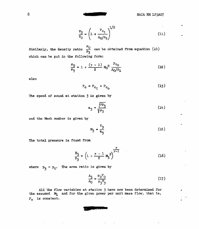
similarly, the density ratio - PO can be obtained from equation (10)
which can be put in the following form: p3
also
Tfie speed of sound at stat ion 3 is given by
a3 = \IC J
1 J
and the Eibstch nuuiber is given by
M3 = a, 3
J
llhe total pressure is found from
- = =3 (l+- Y - 1 %2)7-l p3 2
where p3 = po. %e area ratio is given by
All' the flar variables at station 3 have now been determined for the assumed M1 and for the given power per unit mass flow, that is, PC is constant. . . .

When isentropic flow occurs across the disk, equals po. The Mach
nmuber a t s ta t ion 2 is determined from the area ratio p3
The static pressure p2 is obtained from
- where
% = I33
The density a t etation 2 is obtained from
The velocity V2 is obtained f r o m the continuity of mass flaw
since Ax = Az. The energy at stat ion 2 i e equal to the energy at sta- t ion 3 and is given by *
10
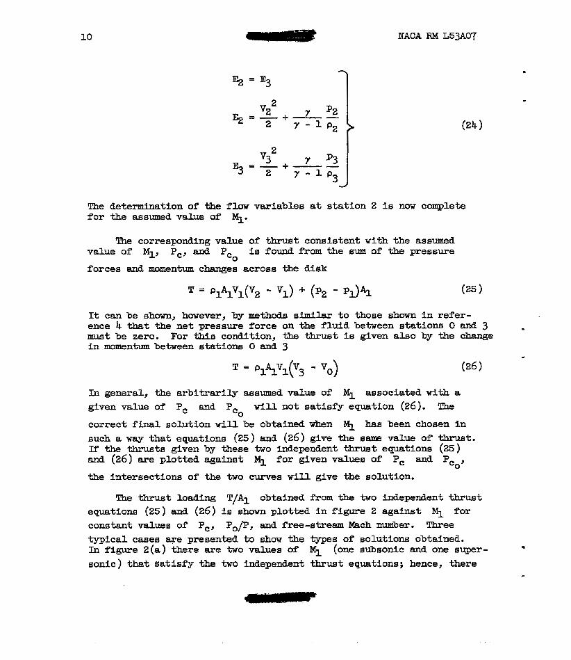
Ez = E3 1
NACA RM L53A07
J
The determination of the flow variables at station 2 is now complete f o r the assumed value of MI.
The corresponding value of thrust consistent with the assumed value of MI, PC, and P is found f r o m the sum of the pressure
cO forces and momentum changes across the disk
It can be shown, however, by methods simllar t o those sham in refer- ence 4 that the net pressure force on the fluid between stations 0 and 3 . must be zero. For t h i s condition, the thrust is given a l so by the change in momentum between stcttions 0 and 3
In general, the mbttrarily assumed value of M1 associated with a given value of PC and P w i l l not satisf'y equation (26 ). The
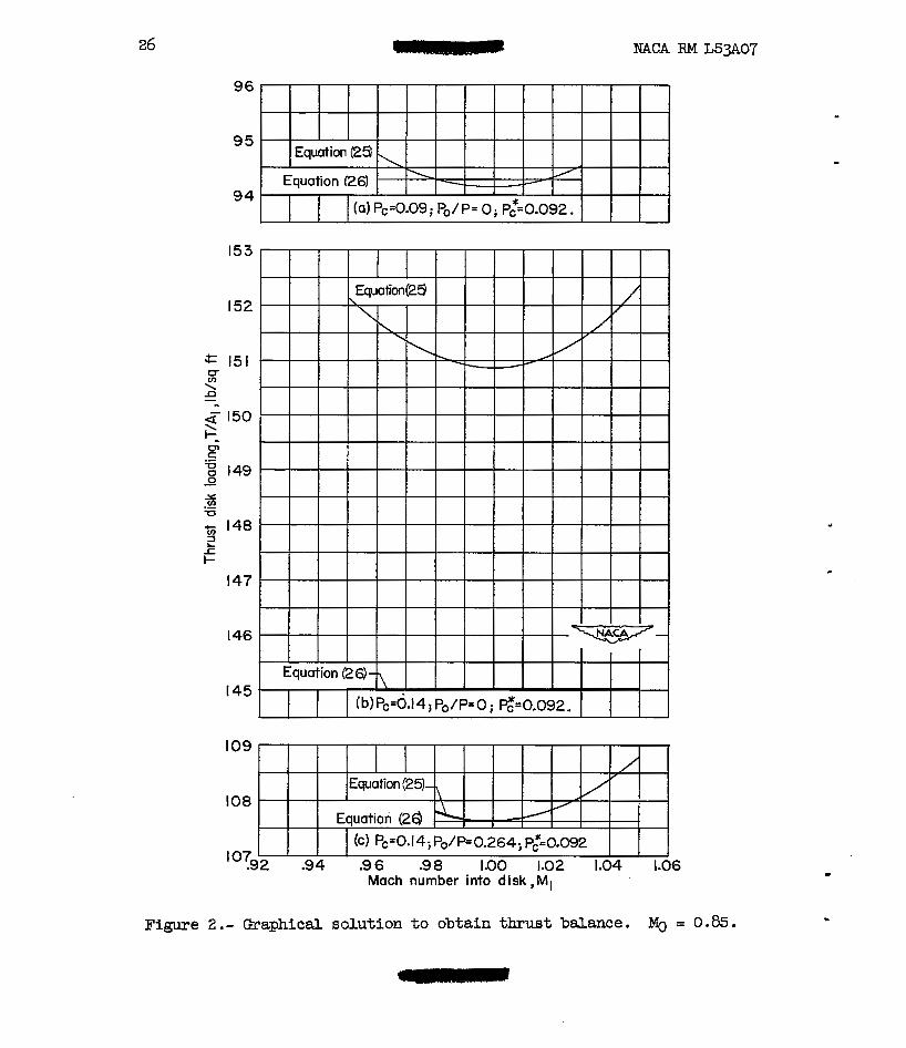
cO correct final solution will be obtained when M.1 has been chosen in such R way that equations (25) and (26) give the same value of thrust. E the thrusts given by these two independent thrmt equations (25 ) and (26) are plotted against MI for given values of PC and Pcoy
the intersections of the two curves w i l l give the solution.
The thrust loading T/A1 obtained f r o m the two independent thrust equations (25) and (26) is shown plotted i n figure 2 against M1 for constant ~ a l ~ e ~ of PC, P o p , and free-stream hkch number. Three typical cases we presented t o show the types of solutions obtain&. In figure 2(a) there are two values of MI (one subsonic and one super- . sonic) that sa t i s fy the two independent thrust equatfone; hence, there
m

NACA RM L53A07 11
I are two possible solutions. In l i ne w i t h the previous discussion, only the subsonic values of Ml w i l l be used. In figure 2 (b ) there are no
indicates that there is a lbnit to the maximum power disk loading fo r which solutions can be obtained for isentropic f l o w throughout the s l ip- stream. For example, if a sufficient part of the parer had gone into losses, a solution would have been possible, such as is sham In f ig- ure 2(c). In figure 2(c) all conditions are the same as in figure 2(b) except that the power loss P o p (drag or shock loss ) is 26.4 percent of -the total parer. In t h i s case only one solution was obtained and that is for MI = 1.0. If P o p is increased for the same values of PC and Mg, two solutions w i l l be obtained, one w i t h M1 subsonic aad one w i t h MI supersonic.
- crossings of the two thrust curves and thua 110 solutions. This f a c t
These resul ts catl be summarized as fo l l a r s : When PC is less than PC*, there are two values of MI (one subsonic and one super- sonic ) that w i l l sa t i s fy the two independent thrust equations. m n P, is equal to PC*, there is only one value of y that produces a s o h - tion, *t is, M1 = 1.0, and the flow is everywhere isentropic. When PC is greater than PC*, no solutions are possible unless arbitrary losses are introduced in the disk. These losses are similar t o losses
flow through the disk is no longer isentropic. - associated with the bhde profi le drag and shocks. Consequently, the
. Tkus far only solutions having ,sibsonic wakes have been considered. It w i l l be sham later under "Results and Discussion" that there is 8 transit ion fYom a subsonic wake t o a supersonic wake a t some value of PC greater than PC*, that is , after the fluw into -the disk becomes choked.
Supersonic wake.- Ik order t o analyze the flow behind the disk w i t h a supersonic wake, the flow out of the disk is assumed t o be similar t o the supersonic flaw out of a nozzle in which the discha;rge or exit pressure is less thasl the auibient pressure a t the exit. !The attendant shock formations in the wske are dfscuseed i n detail i n refer- ence 3 (pp. 172-174). This cmression gives rise to shock losses i n the wake so that the treatment w d f o r the sdmonic-wake solutions no longer is applicable. The following nethod has been used t o obtafn the supersonic-wake solutions .
.
12 NACA RM L53A07
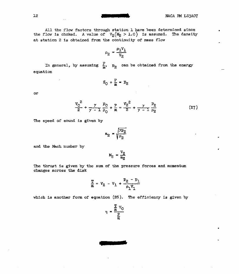
All the flow factors through s ta t ion 1 have been determined since the flow is choked. A value of Vz(% > 1.0) is assumed. The density a t s ta t ion 2 i s obtained from the continuity of mass flow
In general, by assuming E, p2 can be obtained from the energy P
equation
or
The
and
The
speed of sound is given by
the Wch &er
thrust is given
bY
by the sum of' the pressure forces and momentum changes &cross ~the disk
which is another form of equation (25). The efficiency is given by
m

NACA RM L53A07 - The power disk-loading coefficient is given by
" PAg A1 PC = -
V02 2
The solution for obtaining all the flow variables across the disk, the efficiency, and parer disk-loding coefficient is now complete. It is not necessary to make a detailed analysis of a balance of energy and thrust by comparing the t o t a l energy and thrust at stations 2 and 3.
The arbitrary assumption of V2 and produces an infinite num- P
ber of solutions which in general do not represent the maxirmnn-efficiency case. The maximum efficiency, however, is of -particular interest and occurs when the flow thrmgh the disk is isentropic.. For this case, p2 is obtained from the isentropic pressure-density relation
-p2 - -
The value of corresponding to P this isentropic process cam now be c obtained directly f r o m equation (27). It is to be noted that in the
subsonic-wake case, there is a defin€te lfmit to the value of the parer (PC = PC*) the disk can absorb isentropically. For the supersonic-wake case, however, much larger mounts of power ca~l be absorbed isentropically by the disk.
RESULTS APTD DISCUSSION
Ideal Solutions
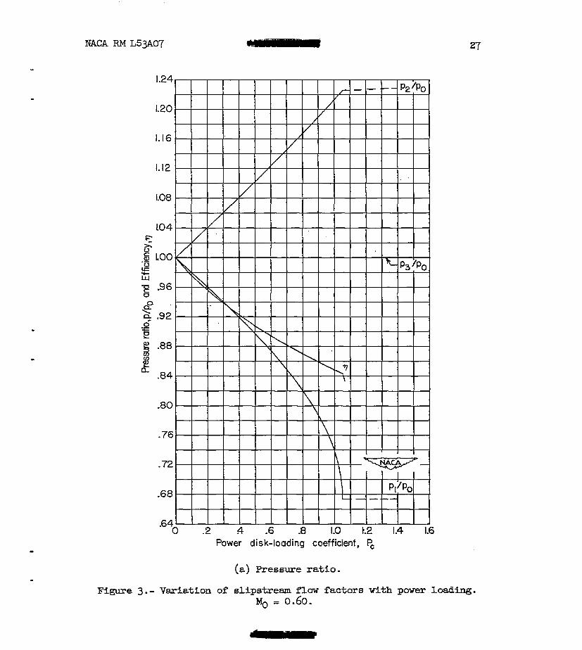
Solutions of the flow variables throughout the slipstream are pre- sented in figures 3 to 8 for forward &ch nmibers of 0.60, 0.70, 0.80, 0.85, 0.9, and 0.95. These results are presented as bkch number and as ratios of pressure, density, velocity (referred to free-stream condi- tions), and ratio of cross-sectional area of the slipstream (referred to the area of the actuator disk), all as functions of. the power disk- loading coefficient PC. The miation of efficiency with PC is pre- sented in the s- figures as the pressure ratios. When the flow into
- 1

14 - . NACA RM L53AU7
the disk is subsonic (% < l), the flow behind the disk (station 2 ) must
sonic wake were obtained. When the flow into the disk becomes choked (MI = l), solutions were obtained for both subsonic and supersonic flows at station 2. For the subsonic-wake case, however, solutions can be obtained only by introducing losses in the disk. A l l curves fo r solu- tions with subsonic flow at station 2 are marked with plain synibols while the curve8 obtained for supersonic fluw at station 2 are marked with S y n i b O l S hsving subscript s (figs . 5 to 8). Choked f luw OCCUTS at the lower value of PC at which there is a sharp break in the curves.
be SU*DSOIliC, a8 Will be S h m later, and only the SOhtiOnS f o r a Sub-
There is R range of power disk-loading coefficient for which both subsonic and supersonic wakes appear as alternative possibilities. Since there is nothing in the equations to indicate which type of f l o w might occur and which efficiency might be obtainable, the results were studied to determine when the change from a subsonic wake to a super- sonic wELke could be expected. A supersonic wake ie possible for all exit velocities for which a shock pattern exists at the exit or extend6 downstream f r o m the exit. The lowest supersonic-wake Msch number which can exist is seen by eaalogy w i t h nozzle flaw to correspond to the con- dftion of 8 normal shock immediately behind the actuator disk or at the exit of a supersonic nozzle. In t h i s case, except for an infinitesimal distance behind the actuator disk, the wake flaw is actually subsonic. Consequently, the subsonic-wake calculations should be applicable to this case snd the losses which it is necessary to assume in order to obtain a solution correspond to the losses in a normal shock at the exit.
A direct calculstion of the &ch nwiber.immediately behind the disk f o r the case with a normal shock at the exit is difficult to make because the boundary pressure at the exit is not known at t h i s atage of the calculation. Emever, since the subsonic- and supersonic-wake calcu- lations should give the same results (corresponding efficiencies and parers are equal) for the normal shock at the exit, the intersection of the efficiency curves fo r the two typea of solution (subsonic- and supersonic-wake solutions ) should correspond to the condition of R normal shock at the exit. In figure 9, the W c h nuuiber behind R normal shock is plotted against the Mach number in fYont of a normal shock (see data from table 3 of ref. 3 ) j this relation is sham by the solid line. DE RbSCiSSRS of the individual points (shown by symbols) which are plotted in figure 9 are the values of % f r o m the subsonic-wake solu- tions at the point of intersection of the efficiency curyes for the subsonic-wake and supersonic-wake solutions. The ordinates of these points are the values of (%) taken from the supersonic-wake solutions at the corresponding conditions. It-is seen that the relation between
s
NACA RM L53A07 . .
15
the subsonic and supersonic values of 4 at the point of intersection of the efficiency curves is exactly that f o r a normal shock.
'phe curves, figures 5 to 8, for flow parameters are S~OWII as solid lFnes for the subsonic-wake solutions up to the transition value of PC and as dashed lines at higher values of PC. The solutions fo r the supersonic wake are sham as eolld B e e , beL-2 at the due of PC for equal efficiencies from the two wake solutions and all higher values of PC. At lower values of PC, the solutions for the supersonic w-ake are shown as dashed lines and are presented only to show the range of calculstions .
The curves in figures 3 to 8 for compressible flow show two impor- tant discontinuities of the flaw parmeters. The f i r e t discontinuities occur at the value of PC at which MI = 1.0 which is called the critical parer disk-loading coefficient and is desfgnated as PC*. Choking cannot OCCUT for the incompressible-flow case; therefore, the miss flow can increase indefinitely as PC is increased, whereaa for compressible flow the mass flow reaches a maximum for a given forward lkch number when the Mach number immediately ahead of the disk reaches a value of 1.0. The second break in the curvee occurs at the value of PC wbere the efficiency for the sribsonic-wake solution is equal to the efficiency for the supersonic-wake solution. -
Cunres for the supersonic-wake solutions are not included for the . lower Mach m e r 6 (figs. 3 and 4). lh these casee extremely high power disk loadings are required t o choke the flow and supersonic calcu- lations for choked flow were not presented as it w a 8 felt the power disk loadings were beyond the practical range for propeller operation.
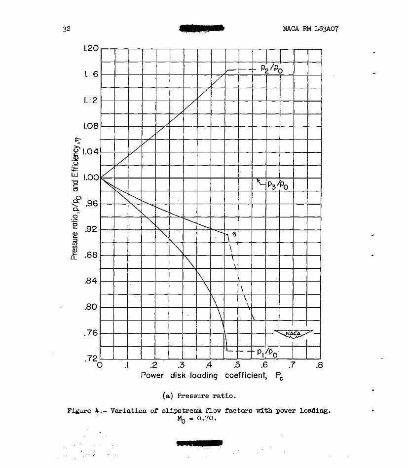
Pressure.- !&e pressure rise through the disk for compressible and incompressible flow a t parer disk loadinga below choking is compared at several forward Fach n-rs in figure 10 for mexfmum-eff iciency condi- tions (no profile losses). For a given value of PC and %, the pres- sure rise through the disk is much greater for compressible flow than for incompressible flar. The figure shuws that the pressure rise for
light parer loadings. The (a) parts of figures 5 to 8 also show that, for a given forward Msch rider when the flow into the disk reaches a %ch number of 1.0, practically no additional pressure rise can be obtained even for large increases in power for -the subsonic-wake solu- tions. The s8me figures also show a large decrease in pressure across the disk for the supersonic-wake solutions. -

16 NACA RPI L5307
Density.- The changes in density axe similar to the changes in pressure.
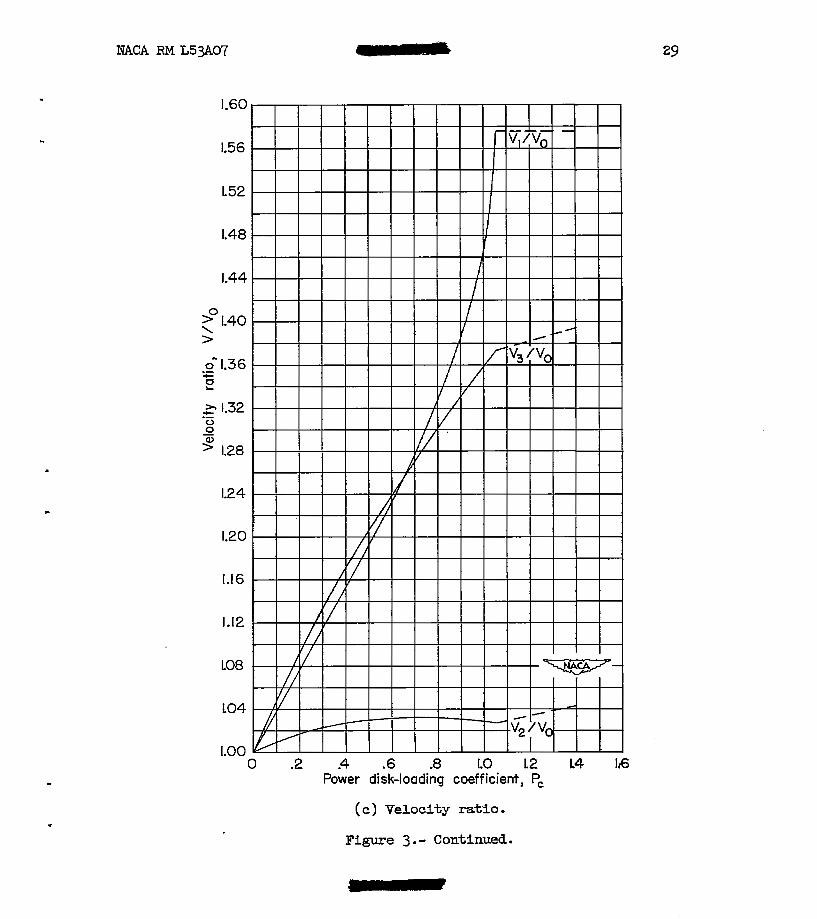
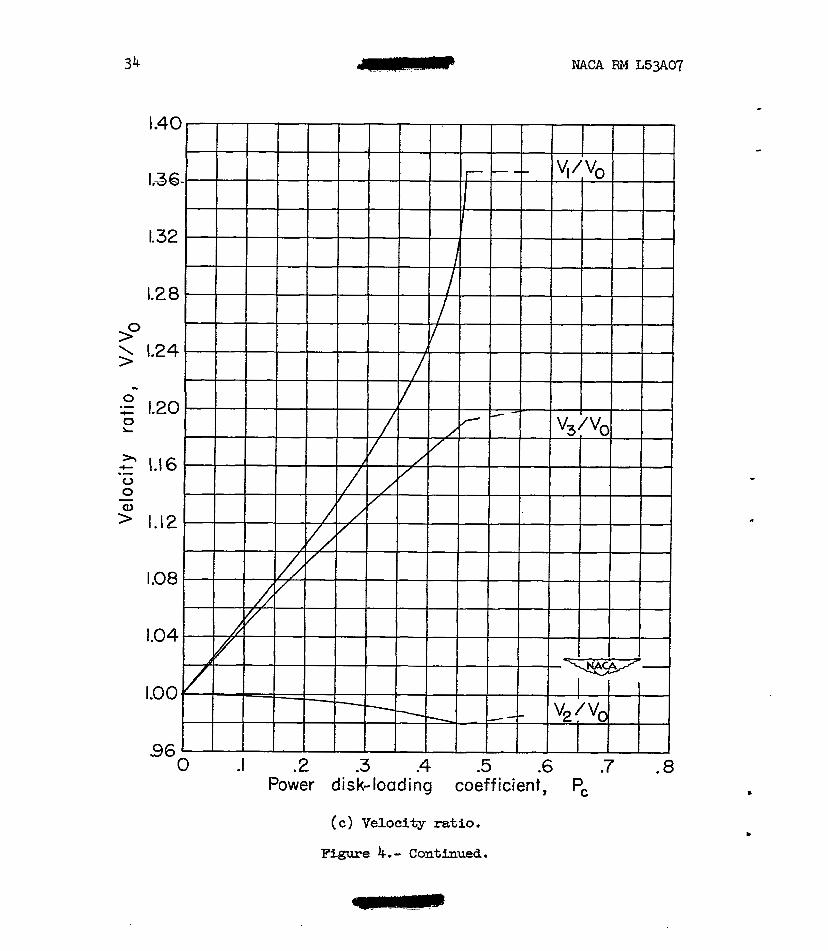
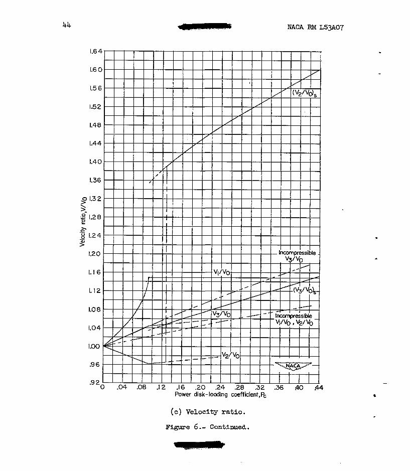
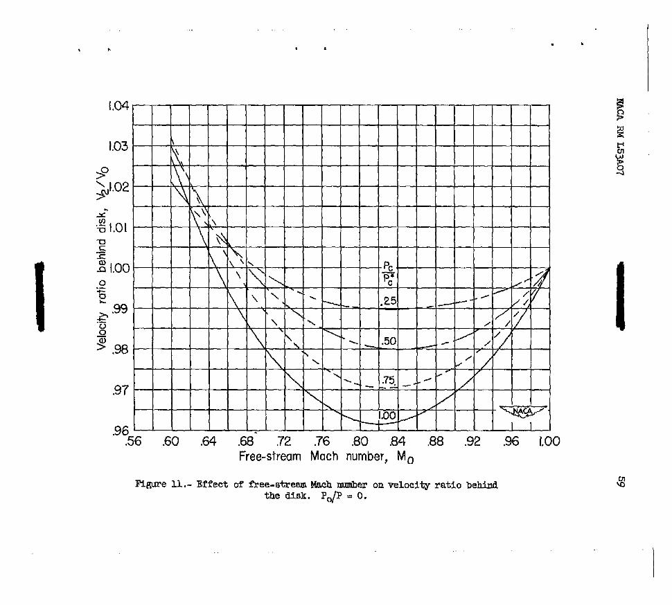
Velocity and Mach nUmber.- The velocity changes are similar to the Mach number changes throughout the slipstream. The velocity in front of the disk is much greater than the incompressible-flow value and the dwference increases with PC up to choking. (See fig. 6 (c ). ) The most significant result is the great drop in velocity through the disk for the subsonic-wake solution, and the great increase in velocity for the supersonic-wake solution. The effect of forward Mach number and power disk loading OR the velocity inmediately behind the disk is pre- sented in figure 11 for the subsonic-wake case. This figure shows that the velocity immediately behind the disk is less than the free-stream velocity for high subsonic Mach numbers for sll parer disk loadings. At lower free-stream Mach nmibers (e. g., MO w 0.65 to 0.69) the velocity behind the disk is greater than the free-stream velocity.
. L
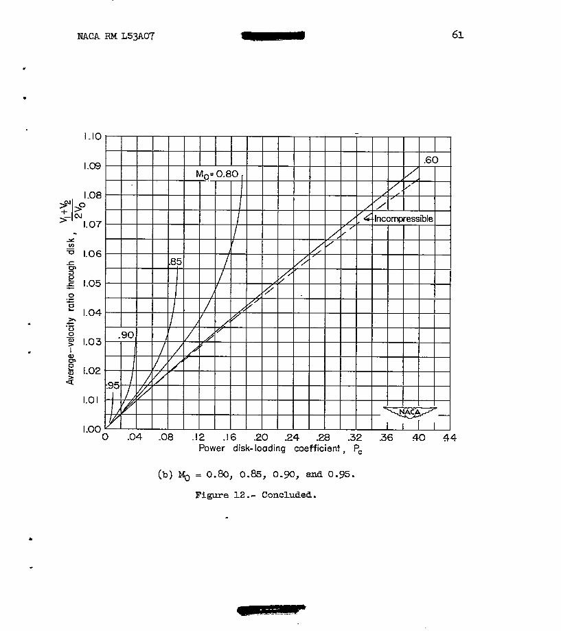
Figure 12 shows a conparison of the average-velocity ratio through the disk for fnCOmpre66ibk and compressible flaws up t0 choking. The
average velocity through the disk VI + vi2 is higher f o r compressible
flow than for incompressible flow, and increases with PC. At Low power loadings, however, there is not much difference.
I
From the great differences in the flow factors for incompressible and compressible flow the use of- conventional incompressible-flow theory for propellers might be expected to give erroneous results in calcu- lating propeller performance characteristics. Coqparison of experimental and calculated results, however, for propellers even at high subsonic k c h nmibers has shown remarkably good agreement in over-all character- istics for light loadings., Thia good agreement may be due to t he fact that the average of Vl and V2 for co~rrpressible and incompressible flow is not greatly different for light power loadings. For high parer loadings, however, experimental propeller characteristics mey differ greatly from calculations based on incolnpressible-flaw theory.
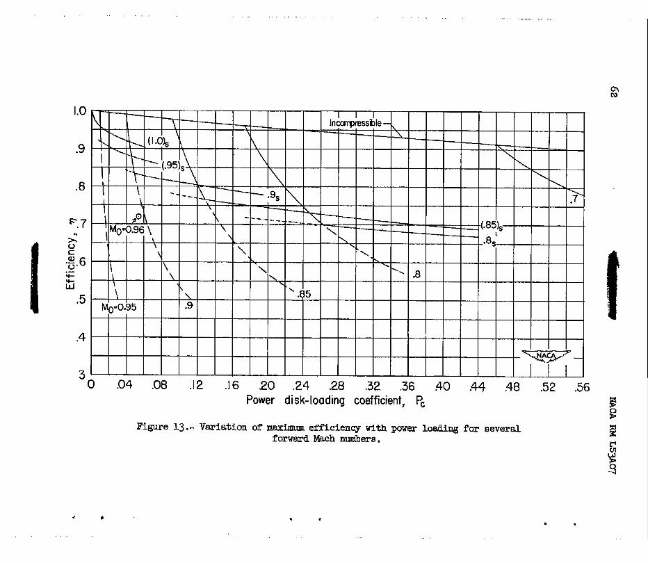
Efficiency.- Figure 13 shows #e vmiatfon of efficiency w i t h parer disk-loading coefficient for all free-stream %ch numbers for both the subsonic- and supersonic-w8ke solutions. The changes in efficiency for a given free-stream b k c h number were discussed earlier in connection with transition of the flow from a subsonic to a supersonic wake. m e drop in efficiency from the subsonic- to supersoni&-wake case (tran- sition drop) becomes less as the free-stream Mch number increases. Consequently, at the high subaonic Mach riders the efficiency level is quite high for the swersonic wake case.

NACA RM L5yL07 17
In figure 13 one max% efficiency point obtained in experiments in the -ley 16-foot transonic tunnel is included for a free-stream Mach number of 0.96 and PC = 0.054 for comparison with acktor-disk results. This efficiency falls between the lines representing the subsonic-wake solution with the flow choked and the supersonic-uake solution. This efficiency is about 16 percent lower than the ideal efficiency calculated for the supersonic wake and this loss represents approximately the blade profile-drag loss. The rest of the losses would appear even without blade profile-drag losses and would show up as shock losses in the wake. TIE efficiency and parer disk-loading coefficient obtained for this propeller show that this propeller has a supersonic wake immediately behind 'the propeller plane.
Erect of Additional Imses
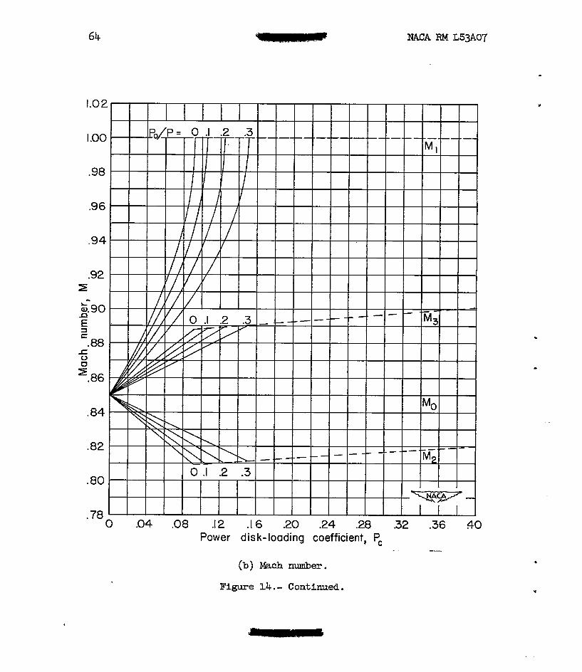
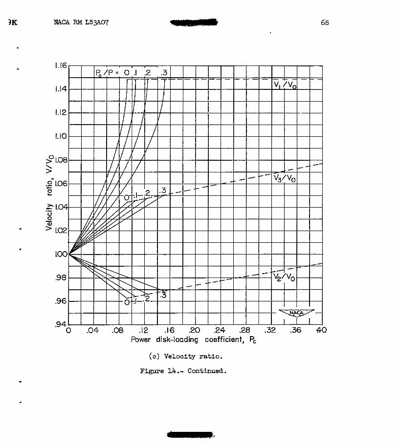
Subsonic wake.- Important effects are produced when additional losses are included in the analysis. These effects &re shown in fig- ure 14 for a forward mch number of 0.85 and for values of Pop of 0, 0.1, 0.2, and 0.3 for the subsonic-wake case. For a given value of PC the deviation of the flow factors from the free-stream values decreases as the profile losses are increased. For a fixed value of Po/P, the limit of the subsonic-wake solution occurs when the v h number MI into the disk reaches a value of 1.0. This limiting condition represents choked flow. The locus of simLlar limit- points for all values of Po/P is designated as the "choke line. I' The choke lines are shown as dashed lines in figure 14. Once the flow becomes choked and the power is increased, solutions can only be obtained by the addition of further arbitrary losses in the disk, that is, choking occurs at higher values of PC. Transition of the flow f r o m a subsonic to a supersonic wake must occm somewhere along the choke llnes.
The effect of additfonal losses on efficiency is s h m in figure 15 for forward Mach nunibers from 0.70 to 0.9 for the subsonic w-ake. The variation of efficiency for constant values of Po/P is shown by the dashed lines. It can be s h m that the efficiency is given by
~
P " 9 -1" where qPo=o P ?Po=O P
is the value of q when 2 = 0 for the
value of PC under consideration. As PC is increased above the value required to choke the flow, the efficiency decreases rapidly.
Supersonic wake.- Similarly, for the supersonlc-wake case, the . addition of profile-losses results in lower efficiencies than sham in

18 NACA RM L53A07
figure 13. The value of PC at which choking occurs w i l l increase with an increase of prof i le loss and the t ransi t ion of flow from a subsonic t o a supersonic wake w i l l occur at some point along the choke l i ne at a higher value of PC than the transition for the zero-profile-loss case.
Previously, it w a s pointed out that the loss in efficiency associ- ated with transition of flow from a subsonic wake to a supersonic wake decreases as the free-stream Mach number is Fncreased. Consequently, it is evident that if suff ic ient parer is added t o produce a supersonic wake, even at a free-stream Mach number of 0.8, a very large loss i n efficiency results (from 96 percent down t o 70 percent, see f ig . 13) . The problem of particular importance, then i s the determination, i f possible, of methods to increase the efficiency by delaying the adverse effects associated w i t h choking the flow. This can be done by the use of actuator disks i n tandem.
Actuator D i s k s i n !Tandem
Solutions for actuator disks in tandem require knowledge of the flow field between the disks. In order to simplify this problem, it can be assumed that the disks are w i d e l y spaced and that only the mass flow passing through the f irst disk passes through the following disks. In addition, it is assumed that the final wake conditions of the leading disk are taken as the free-stream conditions of the following disk. Such a configuration resolves the problem into the solution of a series of single disks f o r which the solutions already obtained for a single disk can be used.
When a single actuator disk is operating a t a condition w h e r e it is absorbing ju s t enough power to produce choking, the addition of more parer w i l l produce a rapid decrease in efficiency. E, however, this additional parer were absorbed by a second coaxial disk located far behind the f i r s t disk, it can be seen tha t the second disk could operate a t a high leve l of efficiency as long as the flow into it were not choked. Consequently, the over-all efficiency of the two disks would be higher than fo r a single disk absorbing the sane' total power.
Solutions have been obtained f o r two, three, and an inf ini te num- ber of disks In tandem using the methods presented in the appendix. No attenrpt w a s made to present all the flow factors since only the effi- ciency that can be obtained a t high values of total parer is of in te res t i n the following analysis.
Calculations were made on the assumption that the flow through the leading disk. Bas .just choked. Additional. parer is then added: only to the following disk u n t i l it becomes choked. The calculations were terminated fo r a f i n i t e number of disks when the flow into the last

MACA FM L53A07 19
..
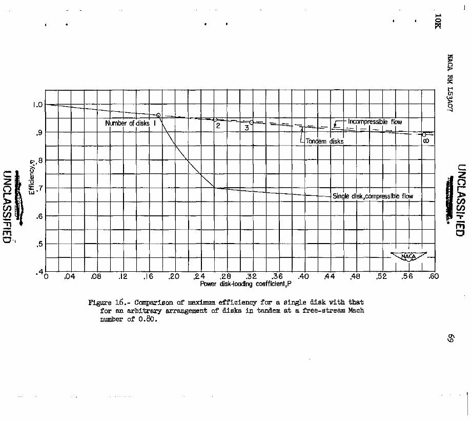
disk became choked and, for an i d i n i t e number of disks, when the flow of t he f i na l wake reached a Mach rider of 1.0. b" this process the addition of power t o any disk does not a l ter the flow conditions at my preceding disk. Each added disk becomes smaller than the preceding disk. This method of analysis was used for mathematical expediency and does not affect the results. For the case being considered (Mg = 0.80), the diameter of the second disk was reduced about 3 percent md that of the third disk about 4 percent. The results of this analysis are pre- sented i n figure 16 for a forward Mach nmiber of O.", as over-all efficiency against power disk-loading coefficient based on total-power, free-stream conditions f o r the front disk and the area of the f ront disk. The efficiency for tandem disks remains almost as high as the incompressible efficiency and is coneiderably higher than it is for the single disk absorbing the same total power. The efficiency f o r the tandem disks is h e r than the incompressible value of efficiency because the mass flow into the tandem disks remEtins fixed as the parer is allowed t o increase. Choked fluw for a single disk occurs at a value of PC = 0.174 and the further addition of power resu l t s in a rapid loss in efficiency until the flow changes from a subsonic t o a super- sonic wake. For tandem disks this rapid loss in efficiency is delayed u n t i l the flow in a l l the disks is choked. Choked flow occurs at PC = 0.263 f o r two disks, PC = 0.319 for three disks, and PC = 0.584 f o r an inf in i te number of disks. Thu, a. considerable increase in high- efficiency parer range results f r o m the addition of one disk; further increases in parer range occur far addi t ional disks but this gain decreases as the number of disks is increased.
-
Since it w a s possible t o obtain a high level of efficiency by adding the power i n more I&m one disk, it is obvi? that the eff i - ciency obtained for a single actuator disk no longer represents the optimum or ideal efficiency f o r a l l operating conditions.
The use of closely spaced disks rather than widely spaced disks i n tandem represents a practical propeller configuration. Experimental results show that final wake conditions are reached a short distance behind propellers and i t is believed the results obtained with w i d e l y spaced disks are indicative of w h a t may be q e c t e d f o r closely spaced propellers. Tests are needed t o determine the effect of spacing on the performance of tandem propellers.
Comparison of the incompressible- and compressible-flow phenomena show -@;e differences in the flow variables across the actuator disk. For the case where only isentropic flow is considered for a n actuator disk, the maxim efficiencies for compressible and incompressible flow
I
20 NACA FM L5307
were found to be the same for power disk loadings ug to nose first required to choke the flow.
When the flow becomes choked, the further addition of power pro- duces a rapid loss in efficiency. This l o se in efficiency is associated with the transition of flaw immediately behind the disk from subsonic to supersonic flow. When the flow immediately behind the disk is super- sonic, the rate of efficiency loas with power disk loading is similar to but greater than that for incompressible flow.
The use of actuator disks in tandem is one method of delaying the large losses in efficiency associated with choked flow, especially at low values of Mach number and high loadings. A level of efficiency almost as high as for incompressible flow could be maintained until the flow in all disks became choked. It is obvious, therefore, that a single actuator disk gives the ideal efficiency only for parer loadings up to those required to choke the flow.
Dingley Aeronautical Iaboratory, National Advisory Committee for Aeronautics,
Iangley Field, Va.
.

NACA RM L53A07
APPENDIX
SOLUTION O F SPECIAL CASE OF ACTUATOR DISKS IN -EM
21 -
For coaxial actuator disks in tandem any two successive disks are assumed to be far enough a p a r t so that the final. wake conditions of the front disk may be assumed to be the free-stream conditions of the fol- lawing disk. The problem is s-lified by the asslmrption that there are no profi le or shock lossea incurred. In addition, only the mass flow passing through the first disk is assumed to pass through a l l the disks. This assumption requires that the area of the second disk be smaller than the area of the f i r s t disk and just the right size t o work on a l l the mss flow. These assumptions make possible the use of solutions already presented for the single actuator disk. Considerations similar to those of reference 4 show that the form of the general momentum equa- tions involving thrust and boundary forces for t h i s case remains the same and that the net boundary force is zero when the static pressures far in front of and far behind the acturator disks are the sane. Fig- ure 17 is a sketch of the stations used in this analysis.
The over-all thrust of the system is given by
a where '3R is the final wake velocity of the rear disk and V is the OF free-stream velocity of the front disk. me parer LSI? added t o the stream by any single disk is given by the change i n e n e r a from its free-stream to its final-stream conditions. Considering only an isentropic flow process this power i s given by
where the subscript n refers to . the nth disk. The t o t a l p e r I? f o r a l l disks is given by
m 1 n
w h e r e t equals t o t a l nuuiber of disks. It can be shown that
(3 1

22 NACA RM L53Aw
The total m e r disk-loading coefficient based on the free-stream condi- tions of the front disk and the area of the front disk is given by
which reduces to
The over-all efficiency is given by
M p 3 R - v?F)v% r l = P
which reduces to
2 9 =
3R 1 + - voF
For isentropic flow the final static pressure and density are the s a m RS the initial free-stream values; consequently, equation (5) reduces to
and equation (6) reduces to
2
M3R 1+- ? =
".F Equations (7) and (8) permit the calculation of the meximum perform- "
mce for disks in tandem with isentropic flow throughout the stream. For these conditions the maximum value of M3 can be 1.0 for an infinite R

NACA RM L53A07
- nuniber of disks
23
and the maximum value of (2) is the value when the ' I 'F - flow into the front disk is choked. Under these coilditions the maximum
values of PC and q then become
and

24 NACA RM L53A07
1. Vogeley, Arthur W.: Axial-Mxwntum Theory f o r Propellers in Compressible Flow. mACA Tm 2164 (corrected copy), lsl.
2. Klawans, Bernard B., and Vogeley, Arthur W.: A Cascade-General- Momentum Theory of Operation of R Supersonic Propeller Annulus. NACA RM 152~06, 1952.
3. Ferri, Antonio: Elements of Aerodynamics of Supersonic Flows. The hchfillan Co., 1949. . . . .
4. G l a u e r t , H.: Airplane Propellers. The Axial Momentum Theory. Vol . IV of Aerodynamic Theory, div. L, ch. 11, sec. 2, W. F. Wand, ed., Julius Springer (Berlin), 1935, pp. 184-187.

Station 0 1 2
Figure 1.- SUpstrceem statione used in the andyais of single actuator disk. Free-stream condltiona M, V, p, p, H, and E m e gsven at station 0.
26
96
95
94
- NACA RM L53pL07
1 (a) Pc=0.09; Po/ P= 0 P:=0.092. 1
Figure 2 ,
Mach number into disk ,MI
,- Graphical solution t o obtain thrmst balance. &-J = 0.85.
.
.
Power disk-loading coefficient, PC
(a) Pressure ratio.
Figure 3. - Variation of slipstream flow factors with power loading. ~0 = 0.60.

28 NACA RM L53A07
(b) Mach number.
Figure 3.- Continued.
9 \ > 0 .- c !2
t
1.60
1.56
152
1.48
1.44
I
1-40
1.3 6
1.32
1.28
1.24
1.20
1.16
1.12
108
LO4
1.00 0 .2 .4 .6 .8 LO 12 L4 16
Power disk-loading coefficient, PC
(c) Velocity ratlo.
Figure 3. - Continued.

30 NACA RM L53A07
Power disk-loading coefficient, PC
(a) Density ratio.
Figure 3 . - Continued.
..

32
1.20
1 .1 6
1.12
1.0 8
F 3 1.04
E a, 0 .-
1.00 z $ .96 .o
E
a c
t
-92
cn 3 cn .88
.8 4
. . .80
.76
.I
NACA FM L53A07
.2 .3 .4 5 .6 Power disk-loading coefficient,
.7 PC
.8
I
(a) Pressure ra t io .
Figure 4.- Variation of slipstream flow factors with parer loading. . ~0 = 0.70.
. . .. -
. .

5K NACA RM L53A07 33
I
1.00 [ MI
.9 6 I
.92
L A
L
a 3 c
Q) .88 E
s / .84 7 -
0 / M3 a z
-80 I
.76
.72
.6 8
.64 0 .I .2 .3 4 .5 .6 .7 .8
Power disk-loading coefficient, PC
(b) Mach &E!?. Figure 4.- Continued.
34 NACA FiM L53A07
( c ) Velocity ratio.
Figure 4.- Continued.

NACA RM L53A07 35
I .I6
1.1 2 ,'
P " " $;o
1.0 8 I .//
/
1.0 4
4 '0
q '1.00
.. = 96 0
0 ' L
t )r
-G .92
n c aJ
.8 8 \ f
.8 4 \I
\ - .
"- t
.80 PI/PO
. 760 .I -2 .3 4 .5 .6 .7 .8
Power disk-loading coefficient, PC
(a) Density ratio.
Figure 4.- Continued.

NACA RM L5y107

..
c
37
Power disk-loading coefficient ,PC
(a) ~ressure ra t io .

0 .04 .08 . I 2 .I6 -20 .24 2 8 .32 .36 .a .44 "
Power disk-loading coefficient,Pc
(b) Mach nuaiber.
Figure 5. - Continued.

39
(c) Velocity ratio.
Figure 5. - Continued.

40 NACA RM L53A0.7
1.1 2
1.0 8
1.04
1 . 0 0
.96
.9 2
\ 8 .88 Q=
e .84 0 z=
h u) t .- 5 a0 .7 6
.7 2
.6 8
.64
.60 (P&r&)*
1
.5 6 "
5 2 1 1 1 -
0 . 0 4 .08 . I 2 .I 6 .20 .24 28 .32 .36 $0 .44 Power disk-loading coefficient ,PC
(d) Density ratio.
Figure 5.- Continued.

6K
"
-
Power disk-toading coefficient, PC
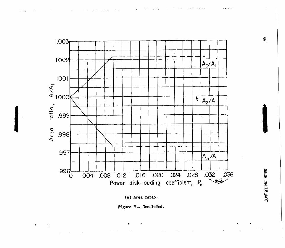
( e ) Area r a t i o .
Figure 5 .- Concluded.

42 WlCA RM L53A07
1. I2
1.08
1.04
1 . 0 0
.9 6
.9 2
‘ -88 F .- 0)
-84 -0 c i.80
4 .76
\
s .72 2 a .6 8
.6 4
.6 0
5 6
.52
.4 8 0 .04 .08 .I 2 .I6 20 .24 .28 .32 .36 $0 -44
Power disk-loading coefficient,P,
(a) Pressure ratio.
Figure 6 . - Variation of slipstream flow factors with power loading % = 0.85.
c

43
(b) Mach number. Figure 6 .- Continued.
44
( c ) Velocity ratio.
Figure 6 . - Continued.

NACA RM L53A07
..
.
1.08
104
LOO
.9 6
92
.8 8
0
2.84 Q
.Q I.
.80
@ 2 .76
.7 2
.6 8
.6 4
.6 0
.56
.5 2 0 €€€€€€I .04 .08 .I 2 .I 6 20 .24 28 -32
Power disk-loading coeff icient,Pc
(a) DenEity ratio.
.3 6 40
Figure 6 .- Contimed.

(e) Area ra t io .
Figure 6.- Concluded.

U C A RM L5y107 ” - II) 47
L I 2
LO 8
10 4
1.00
.9 6
.92
.84 c3
.6 8
.6 4
.6 0
-5 6
.5 2
(a) Pressure ratio.
Figure 7.- Variation o f SlipEtream f l o w factors with power loading. % = 0.90.
__I

48 NACA RM L5307
.08 ,I 0 .I 2 .I 4 Power disk-loading coefficient ,PC
(b) Mach number.
Figure 7.- Continued.
.I 6 .I 8 .2 0

NACA RM L5307 49
- (c) Velocity ratio.
Figure 7.- Continued.

50 NACA RM L5y107
(a) Density ratio.
Figure 7.- Continued.

.. .
Figure 7.- Concluded.
. . . . . . . . . . .

52 NACA RM 1,5307
(a) Pressure ratio.
Figure 8.- Vaziation of slipstream flow factors with power loading. % = 0.95.

e
NACA RM L53A07 53
(b) Mach Iluniber. Figure 8.- Continued.

54 NACA RM L53h07
c
Power disk-loading coefficient, PC
(c) Velocity r a t io .
Figure 8.- Continued.

NACA RM L53A07 -L 55
. 1 . 1 2
1.08
1.0 4
1.0 0
.8 4
.8 0
.7 6
.7 2
Power disk- loading coefficient ,PC
(a) Density ratio.
Fibme 8.- Continued.
. . . . . . . . . . . . - . . , . . . . . . . .. . . . . , . . . . . . - . . . . . . . . .
Power disk-loading coefficient, PC
(e) Ares ratio.
Figure 8.- Concluded.
e I
. . . .

PK NACA RM L53A07 57
Figure 9.- Wch number re la t ion for normal shock and correlation with solutions from actuator-disk theory.

58
.52
.48
.44
.4 0
.3 6
%I@ m .32 t c 0) 0
0 a, 0
”
E .28
.- % .24
2 2 -20 2
L I
rn
a . I 6
.I 2
.08
.04
WCA RM L53A07
.04 .06 .08 .I 0 .I 2 .I 4 . I 6 .I 8 Power disk-loading coefficient, PC
c
Figure 10.- Disk pressure-rise coefficient for inCOmpre6Sible and unchocked compressible flows.
. . . .. , .. . . . . . .
L
.4 U J
56 .60 .64 .68- -72 .76 .80 .84 -88 .92 .96 1.00 Free-stream Mach number, M,
FlgLR’e 11.- Ef fec t of fiee-etre!#n EL& der on velocity ra t io b e W the disk. Po/p = 0.

. . - . .. . . . . . . . . . . . . . . . . -. . . . . . . . . . . . . - .. . . . . . . . . . . . . . . . . . . - . . .
(a) % = 0.60, 0.70, and 0.80.
Figure 12.- Ccmpariam of average-velocity ratio through disk far incompressible and compressible flov6 up t o choked condltlon.
, ,
61
(b) % = 0.80, 0.85, 0.90, 0-95.
Figure 12. - Concluded.
. . - . . . . . .
. . .....

1.lC v
LO€
LOE
LOL
1.02
0
2 1oc - 0 .- + .98 z 2 3 96
a E! v) - VI
-94 - .92
.90
88
.86
3 -
;-
c -
j -
I (
- - - -
-
-
- - - -
-
- -
-
.84 - 0 .04 ,08 .I2 .I 6 -20 .24 28 -32 -36 40
Power disk-loading coefficient, PC . (a) Pressure ratio.
Figure 14.- Effect of p ro f i l e losses on the slipstream f low factors for subsonic wake. % = 0.85.
64
- -
- - - -
-. -
- -
- - - - - - -
- - -
- - -
- . . - -
0 .04 .08 .I2 .I 6 20 .24 .28 32 .36 40 Power disk-loading coefficient, PC
. . --
(b) Mach number.
Figure 14.- Continued.
65
.
Power disk-loading coefficient, PC
(e) velocity r a t i o .
Figure 14 .- Continued. .

66 NACA RM L53A07
P
Power disk-loading coefficient, PC
(a> Density ratio. Figure 14.- Continued. .

.- .
0 .04 .08 t
.I 2 .I6 2 0 .24 .28 . 32 Power disk-loading coefficient, PC
(e) Area ratio.
figure 14.- Concluded.

. " . ..
I .o
.9
.8
.4
." 0 .04 -08 .I2 .I 6 .20 .24 .28 -32 .36 .40 44 48 .52 .56
Power disk-loading coefficient, pC
Figure 15.- Effect of profile losses on efficiency. Subsonic vake.
. . .. .
I .
.9
F. 8

. . .. ... . . . . "
I
I
I
Station 0, 'F 2R 3 R 'F %I OR 'R I
-"--+
1
- Front unit Rear unit
I * I.

.