1989009314 - nasa · nasa avscom technical memorandum101442 technical report 88-c-040 t and d.p....
TRANSCRIPT

NASA AVSCOM
Technical Memorandum101442 Technical Report 88-C-040
t
and
D.P. TownsendLewis Research CenterCleveland, Ohio
PreparedfortheFifthInternationalPowerTransmissionandGearingConference
• sponsoredby theAmericanSocietyofMechanicalEngineersChicago,Illinois,April25-27,1989
usAAVIATIONSYSTEM8COMMAND
AViATiONR&TACTMTY
"'_ .......... 1989009314
https://ntrs.nasa.gov/search.jsp?R=19890009314 2018-06-15T05:48:39+00:00Z

VIBRATION SIGNATUREANALYSIS OF MULTISTAGEGEAR TRANSMISSION
F.K. Choy, Y.K. Tu, and M. SavageDepartmentof MechanicalEngineering
Universityof AkronAkron,Ohlo 44235
and
D.P. Townsend
National Aeronauticsand Space AdministrationLewis ResearchCenterCleveland,Ohio 44135
ABSTRACT [I] identitymatrix
An analysis is presentedfor multistagemultimesh [J] rotational(mass moment of Inertia)gear transmissionsystems. The ana]yslspredicts the matrixoverallsystem dynamicsand the transmissibi]ityto thegear box or the enclosed structure. The modal synthesis KKtlK gear mesh stiffnessbetween ith and Kthapproachof the analys_s treats the uncoupled lateral/ rotortorsionalmodal characteristicsof each stage or compo-nent independently. The v_brationsignatureanalysls [Ks] shaft stiffnessmatrixevaluatesthe global dynamics coupling in the system.The method synthesizesthe interactionof each moda] [Kxx],[Cxy] bearingdlrect and cross-couplingstiff-componentor stage with the nonlineargear mesh dynamics [Kyx],[Kyy] ness matrixand the modal supp¢,rtgeometry characteristics. Theanalysis simulatestransientand steady state vibratlon [M] mass-lnertlamatrixevents to determinethe res_qt_ngtorque variatlons,speeds,changes, rotor Imbalancesand supportgear box Rci radlus of gear in the ith rotormotion excltations. A vibrationslgnatureana]yslsschemeexamines the overalldynamic characteristicsof TF gear generated torquethe system,and the Individualmoda] componentresponses. The gear box vibratlonanalysls also exam- XF,YF gear forces In x- and y-dlrectionsines the spectral characteristicsof the support system.
Xcl,Yci gear displacementsin x- andNOMENCLATURE y-dlrectlc of the Ith rotor
Ai(t) moda_ function of the ith mode in SKi angle of tooth mesh betweenkth and ithx-direction rotor
Art(t) moda] function of the Ith mode In [X2],[_t2] lateraland torsionaleigenvaluedlago-e-dlrectlon nal matrices
Bl(t) modal functlon of the ith mode In [¢]K,[¢t]K lateraland torsionalorthonormalelgen-y-dlrection vector matrices of the kth rotor
[Cxx],[Cxy] bearingdirect and cross-coupling INTRODUCTION
ECyx],[Cyy] damplng matricesThe art and scienceof analyzlnggear transmisslon
[Ct] torslonaldamp%ngmatrix systemscontinue to Improve. Power transfer Is neces-, sary from source to appllcatlonIn mechanlcals}stems.
Fx(t),Fy(t) external excltatlonforces Today'sengineersand researchersnow delve Into areasof innovativeadvancement. They seek to quantify,
Ft(t) external excltedmoment establish,and codifymethods which can make gear sys-tems meet the ever-wldenlngneeds of advancing tech-
FGx(t),FGy(t) gear mesh force in x- and y-dlrectlons no]ogy. Thelr obJectlvesare basic ImprovementsIntransmlssionllfe, efflclency,ma}ntalnabilIty,and
FGT(t) gear mesh torque reliability. They also seek to reduce noise,weight and
I
;
'=-' " "" 1989009314-002

%!
vibrationduring transmissionoperation. Gear transmls- n "
sion system studieshave includedtwo main efforts. XF _ [-Rclecl- RcKecK + (Xcl - XcK)C°S_KiThese studieshave been on: (1) the 1ocallzedtooth " KtKistress/thermaleffectsdurlnggear interactions,and I.I(2) the overall global dynamicbehaviorof the s);tems, i_K
The objectiveof this paper Is to ana]yze the over-
a11 globa] dynamicsof multistagegear systemsusing - YcK)sin _Ki]c°s _Ki (4)1ocallzedgear stress/dlsplacementrelatlonshlps. Equa- + (Yclt_ons of motion are developedfor each gear stage inboth lateraland torsionaldirections. Gear mesh force Summing the forces in the Y-directionresultsin:and moment relationshipscouple the lateraland tor-slonal vibrationsand the dynamicsof each gear stage, n
Orthonor_almodes of the system transformthe equations XF __ L[-Rcieciof motion to moda] coordinates. A self-adaptivevarla- " KtKi m RcKBcK (Xci XcK)COS+
SKi
ble time stepping integrationscheme calculatesthe i=Itransientdynamicsof the system (Choy,1988). A typi- i_Kcal three-stagemultimeshgear system serves as an
example. The resultsof the globaldynamics of the sys- ] (5)tem are examined in both time and frequency domalns + (Yc1 - YcK)sin _Ki sin _Kiusing a FFT (Fast FourierTransform)procedure(Choy,19B? and IgBB). Summingmoment in the Z-d_rectionresults in:
DEVELOPMENTOF EQUATIONSOF MOTION n
For a single stagemuIt_mass gear-rotor-bearlng TF = _ RcK[KtKi(-Rcieci- RcKecK)] (6)system,the equationsof motion In the X-Z plane in I=1matrix form (Choy,1987; David, 1987 and 1988) are: i_K
[M]{_}+ [Cxx]{X}+ [Cxy]{_}+ [Kxx + Ks]{X} where n is the numberof stages in the system.
= {Fx(t)}, {FGx(t)) (I) MODAL ANALYSIS
In the Y-Z plane, the equationsare: To reduce the computationaleffort,the numberofdegrees-of-freedomof the system is reducedthrough
[M]{_}• [Cyx]{_}+ [Cyy](y}+ [Kyy + Ks]{y} moda_ transformation. Orthonormalmodes for each stageresult from solvingthe system homogeneouscharacteris-
+ [Kyx]{X}= {Fy(t)}+ {FGy(t)} (2) tic equations. For lateralmodes, the equations are:
Here Fx and FY are f°rce excltati°nsfr°m the [ Kxx + Kyy]{x}= 0 (7)effectsof imba1_nce,shaft bow and supportbase motion. [M]{_} + 2FGx and FGv are forces Inducedfrom the gear meshinteraction_ith other stages.
The torsionalequatlonof motlon of the single For torslonalmodes, the equations are.siege system is:
[J]{_}+ [KT]{e}: 0 (8)[J]{6} + [KT]{e}= {FT(t)}+ {FGt(t)) (3)
Averaged X- and Y-directlonsupport stiffnessesbringIn Eq, 3, Ft representsthe externallyinducedtorque the calculatedmode shapes closer to reality. Using theand FGt representsthe gear mesh Inducedmoment. Note modal expansion theoremyields (Choy, 1987):that EQ5. I to 3 repeat for each gear stage. The gearmesh forces couplethe force equationsfor each stage to m
each other and the torsionalequations to the lateral (x} = ,_ AI{¢I} (9)equatlons (Davld,1987; Lln, 1988;Mitchell, 1983). i=lTorsional,lateraland interstagecoupling relation-
ships appear In the next section, m
COUPLING IN GEAR MESHES {Y} " Bi[¢i} (I0)
l=IGear mesh forces and moments are functionsof the
relativemotion and rotatlon betweenthe two meshing m
gears and the correspondlnggear mesh stlffnesses. {e} . __ Ati{Qtl} (II)These stiffnessesvary in a repeatlng nonllnearpattern _=l(Cornell,lOB1; Pike, 1987; Savage, 1986). The pattern
repeatswith every tooth pair engagementand acts as a where m _s the numberof modes used. With the follow-sourceof excitationat each mesh. Figure I shows thecoordlnatesystem for the followingforce and moment Ing orthogona]Itycondltlons,equations. Summingthe forces, which act on the Kthstage of the system, In the X-directlonresults In:
ORIGINALPAGEISOF POORQUALITY
1989009314-003

OR,QI.A,PAQEISoFPOOR(UAUTY[@]T[K][¢I . [X2] m
,g \'1
- RcKecK)I/j (19)the equations of motion in modal coordin_tes become:
i;' ('_} + [$]T[Cxx][¢]{A} + [¢]T[Cxy][@]{B} + [X2] {A} where Z is the station location of the gear tn the Kth
p [ ] [¢]T{Fx stage (Boyd, 1987; August, 1986).+ [¢]T Kxy [¢]{B} , (t) + FGx(t)} (14) SOLUTION PROCEDURE
(§}+[(_]TFCyy l[']{_} +L J [(_]TFCy X][_)]{/_} +L J I. JrX21 {B} Rearrange the modal equations of r,otion developed inEqs. (14) to (16) into:
+ [¢]T[Kyx][¢]{A} : [¢]T{Fy(t) + FGy(t)} (15) X-equatlon
{Xt} �[$t]T[CT][¢t]{At} + [)'2t]{A t} {;_} =-[¢]T[Cxx][C]{A}- [¢]T[Cxy][¢]{E3}- [X2]{A}
: {Ft(t) + FGt(t)} (16;
;- Thus, the qear mesh force and moment coupling equations Y-equatlon
for the Kt_ stage in the moda, form are: {_} = _[_p]T[Cyy][¢]{B}, [¢]T[Cyx][#p]{A}, [X2]{8}m
n - [¢]T[Kyx][@I{A} + [¢]T{gy(t) + FGy(t)} (21). *Kjz KtK [-Rc4ci-RcKecK
t=1 and, e-equation;3=I I_K
{;_t } = -[¢t]T[CT][¢t]{At} - [X2t]{At}
+ (Xcl- XcK)C°S a'Ki + (Yri- YCK) sin °{KI]COS O_KI + [¢t]T{Ft(t)+ FGt(t)} (22)
A variable time stepptng Newmark-Beta _ntegration schemeevaluates the modal veloctty and displacement at each
(17) time Interval. In turn, Eqs. 9 through 11 transform the
modal displacements Into absolute/relatlve dlsplacementsm in fixed coordinates.
[¢]_{YF } ¢KJ( KtKi _Rclec i _ RcKecK DISCUSSION OF RESULTS
l=l To demonstrate the appllcatlon of the analyticalJ=} I_K method, a three-stage multlmesh gear system serves as
an example. Figure 2 shows the geometry of the gear
L system. Stage I Is the driver stage. The stage I geardrlves both the output gears dlrectly at a speed of
( ) ( ) ] 1500 rpm. Its input torque of 2.25 kN-m ts spltt+ Xcl XCK cos _KI + Ycl - YcK sln C_Kisln _KI equally between the two output stages. All the meshesare Identical with 36 teeth and a contact ratlo of 1.6
t as shown tn Fig. 3. Although slmllar, the lateraI sup- i[
port stiffness for stage 2 is greater than that for(18)
3
i
1989009314-004
i/
stage 3. The systemhas only mlnlmal imbalancesto make 3. Knowledgeof modal excitationsprovidean under-the torsionalvibrationof the systemmore pronounced standingof the vlbratlonalcharacteristicsof thethan the lateral. Figure 4 shows the lateralvibration systemwhich can result In improved transmissionper-orbits ?or al] three stagesat the mesh locatlons. Note ?ormanceand durability;andthat the differenceIn orbit sizes resultfrom the dlff- 4. The coupling effectsof connectedstructureserencesIn Imbalanceand shaft stlffnessfor each stage, such as the gearboxare easlly Included In the existingHhile stages2 and 3 maintain a relative circularorbit, modal analysis without sacrlficlngthe above advantages.stage I exhlbltsan e_llptlcalmotlondue to the toothmesh stiffnessinteractionswlth stages2 and 3. REFERENCES
Figures5 and 6 show the gear mesh forces In boti_time and frequencydomains between stages I-2 and 3-4. August,R. and Kasuba, R., 1986, "Torslona]A substantiallylargerforce Is present In the I-3 mesh Vibrationsand Dynamic Loads in a Basic PlanetaryGearthan in the 1-2 mesh. This is mainly due to the fact System,"Journal o? Vibration,Acoustics,Stress, andthat stage 3 possesses_ higher vibrationalmagnitude Rel_abllltyIn Desiqn,Vol. lOB, No. 3, pp, 34B-353.than stage 2. The orbi sizes shown In Fig. 4 illus-trate this difference. Stage 3's support stiffness Is Boyd, L.S. and Pike, J., IgB?, "EpicycllcGearless than that of stage2. Dynamics,"AIAA Paper B7-2042.
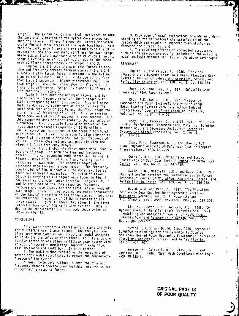
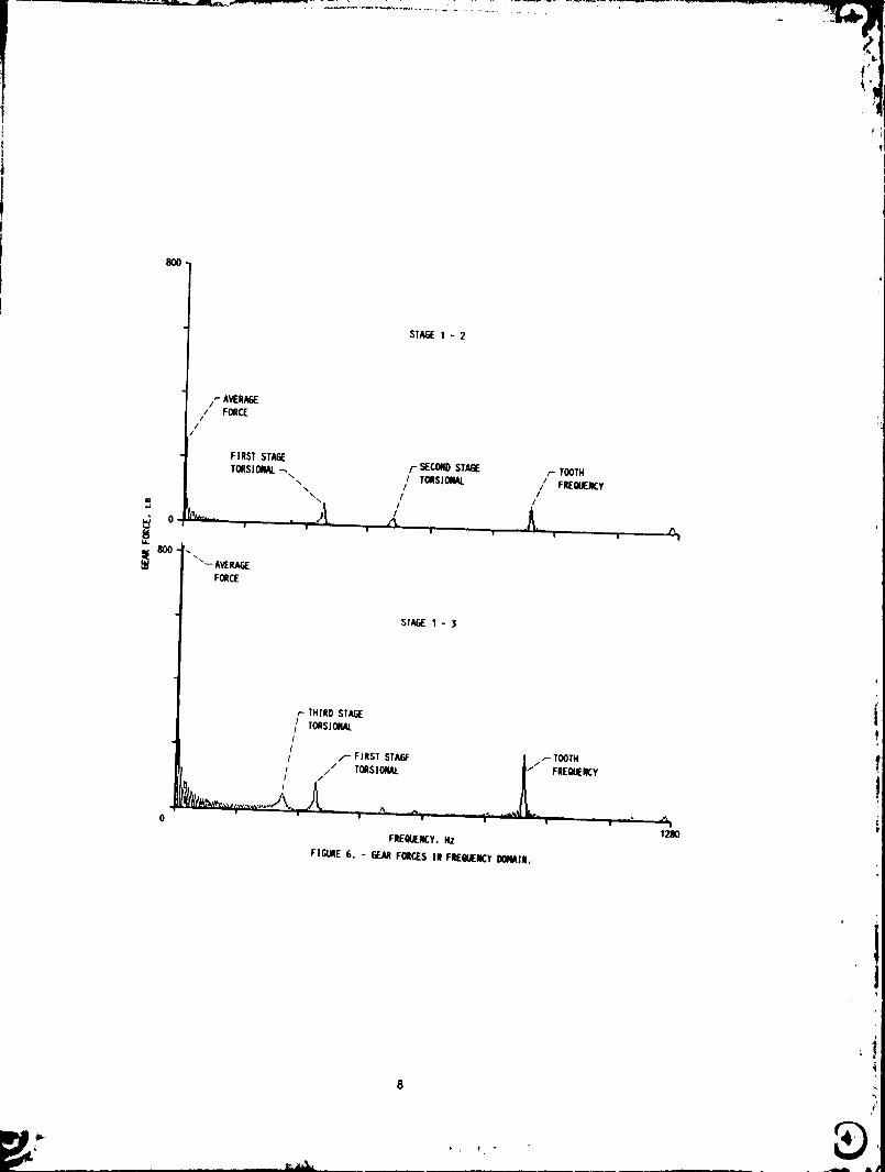
Table ] lists both the undamped lateraland tor-sionalnatura]frequenciesof all three stages with Choy0 F.K. and Li, H.H., ]9_7, "Frequencytheir correspondingbearing supports. Figure 6 shows Component and Modal SynthesisAna]yslsof Largethat the dominatingcomponentsat stage I-2 are the Rotor-BearlngSystemswlth Base Motion Induced
tooth mesh frequencyof gOD Hz and the first stage tot- Excltatlons,"Journalof the Franklin Institute, _,siGnalnatJralfrequencyof 355 Hz. A large average Vol. 323, No. 2, pp. ]45-]68. i_force comp_)nentat zero frequency Is also present. Butthis componentdoes not contributeto the transmission Choy, F.K., Padovan, J., and Li, H.H., 19BB, "Rubvibrations. A c:nsiderab]eforce also occurs at the In High PerformanceTurbomachlnery,Modeling, So]utloninput shaft rotationalFrequencyof 25 Hz while a Methodology,and Signature Analysis."Mechanicalsmallercomponent is present in the stage 2 torsional Systemsand Signal Processlnq,Vo]. 2, No. 2,mode at 550 Hz. A small force echo is also present In pp. Ii3-133.stage 2 at the stage 3 torsionalnaturalfrequencyof280 Hz. Slmilarobservationsare possible with the Choy, F.K., Townsend, D.P., and Oswald, F.B.,stage 1-3 fc_ce Frequencydiagram. 1988, "DynamicAnalysis of Multimesh-GearHelicopter
Figure_? and 8 show the first three modal contrl- Transmissions,"NASA TP-2?Bg.butionsof stage I in both the time and frequencydomains. The correspondlngmode shapes are In Fig. g. Cornell, R.N., IgBl, "Complianceand StressFigure7 shows both Fixed (d.c.) and v_ry}ng (a.c.) Sensitivityof Spur Gear Teeth," Journalof Mechanicalresponsesin each mode. The responsemagnitude _, Vol. I03, No. 2, pp. 4_7-45g.decreaseswith Increasingmode number. The frequencydomain plot of Fig. B shows all the modes excitedat Davld, J.H., Mitchell, L.D., and Daws, J.W., IgB?,their own naturalfrequencies. The ratio o? fixed "UsI,_gTransfer Matrices for ParametricSystem Forced(d.c.) to varylng (a.c.) signalmagnitudes in Fin. 8 Response,"Journalof Vibration,AcgustIcs, Stress, anddecreases as the mode number Increase. Figures iO, l] ReIlabl]ItyIn Design,Vol. log, No. 4, pp. 356-360.and ]2 are plots of the time response,frequencyresponseand mode shapes for the first lateralmode of David, J.W. and Park, N., ]gB7, "The Vlbrationeach stage. These flguresprovlde the modal Informatlon Problem In Gear Coupled Rotor Systems " Rotatin_ Iof the lateralvlbratlonof all three stages. Note that MachineryDynamics, Vol. 2, A. Muszynska andthe rotationalfrequencyof 25 Hz Is excited In all J.C. Simmons, eds., ASME, New York, lgBT, pp. 297-303.three stages. Figure l] shows that stage 3, the firstlateralfrequencyof ]IS Hz iS also excited. This Is Lin, H., Huston, R.L., and Coy, J.J., 1988, "Ondue to the characteristicof its mode shape which Is Dynamic Loads In Parallel Shaft Transmisslons: Part lsho_n in Fig. 12. - Modellingand AnaIysls,"Journa] ofMechan_sms,
Transmissionsand Automatlon In Deslgn,Vol. I]0,CONCLUSIONS No. 2, pp. 221-226. _i
Thls paper presents a vibrationslgnatureanalysis M_tchell0 L.D. and Davld, J.W., IgBS, "Proposedfor multlstagegear transmissions. The analysls com- Solutlon Methodologyfor the DynamicallyCoupledblnes gear mesh dynamics and structuralmodal analysls NonlinearGeared Rotor Mechanlcs Equations,"Journalofto study the transmlsslonvlbratlons. This Is a compre- Vlbratlon,Acoustlcs,Stress, and Rellablllt_Inhenslvemethod of analyzingmultistagegear system wlth _, Vol. I07.effectsof geometry complexity,supportflexlbil_ty,mass Imualanceand shaft bow. In thls method: Savage, M., Caldwell, R.J., Wisor0 G.D., and
I. The modal method transformsthe equations of Lewiclkl,D.G., IgB6, "GearMesh ComplianceModellng,"motion Into modal coordlnatesto reduce the degrees-of- NASA TM-BBB43.freedomof the system;
2. Gear Force observatlonsIn both the tlme andfrequency domainsprovldegood Insights Into the sourceof dominatingresponseforces;
ORIGINAL PAGE IS
OF POOR QUALITY )4
h
1§89009314-00-"5
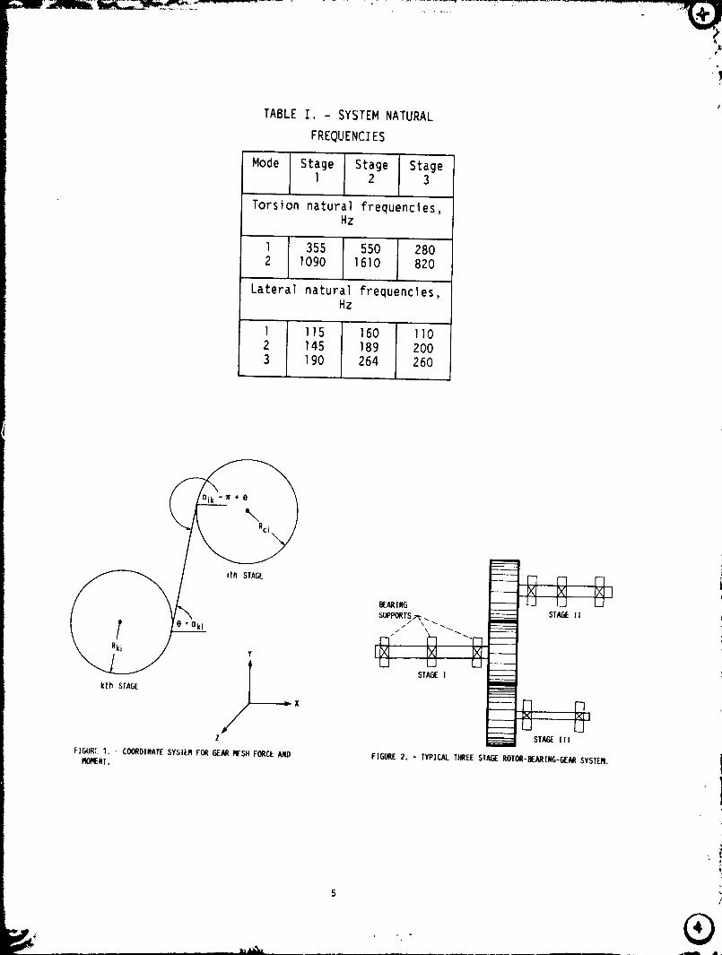
TABLE I. - SYSTEM NATURAL
FREQUENCIES
Mode Stage Stage StageI 2 3
Torsion natural frequencles,Hz
355 550 2801090 1610 820
Lateral natural frequencies,Hz
1 115 160 110
145 189 200190 264 260
i-I I-] I-I i
u i/ II
SUPPORTSTt_ -. _ STAGEI I
_k___ e : "ki iXi """ " ""
" i'-1 ""T-I ----I N N--
U u U _STAGEI
kth SFAGE | -_-1 --0 0_l
,, IU U
STAGEIllZ
FIGURE1. - COORDINATESYSTEMFORGEARMESHFORCEAND FIGORE2, - TYPICALTHREESTAGEROTOr-BEARING-GEARSYSTEM.M(_I_NF,
5
1989009314-006

6 ;'/
1989009314-007

ORIGINALPAGE ISOF POOR QUALITY
2500
SIA_ 1 - 2
i STA_ I - 3)
0
o 1611
FIGURE_, - _ F_C[$ IN TI_ _lN,
7
i_.._ '
- ' 1989009314--0_0"8
!,
STAGE1 - 2
//" FORCE
FIRST STA_ F SECONDSTAEE r TOOTH
TO_SIONAL_,. / TORSIONAL / FREOIJEI_Y",, i /
x / /
j
0 ' ........ .. - _% , t_i ! | i ! ! | " " e
800- """-- AVERA6[FORCE
STAI_E1 - 3
r- THIRD STAGE
/ T_SI_I
i / /- FIRST STAE_ | .._TOOTH
[ .// TORSIONAL _t FIIIEGUEIgY_ ........J k ..
0 1280
FREQUENCY.HZ
FIGURE E. - EEARFOllrJrs III FREiNJIEIKYDOIMIR.
8
..... "_ 1989009314-009

_01_ 2
-.001
! i u ! u - ! r •
.00012' !
J
-.0_12 _ _ r-
TIME, _S[C
Fzr__RE7. - FIRST STAGE [O_SIO_IA[ MO_l_ [XCIIA/IO_ IN IIM[ IX]l_lll.
9
1989009314-010

10
"_ 1989009314-011

I
al,01q
.0]1 _ 1 - STFJ__1
°V-vA
.0014 •.002- MODEI - STAGE2
-.002 _ , ,_ ,, , , , , , 0 - -_'--_- ,-_ . , • , • _------_-._--_
•0_j1 1 lq01_ I - SIA_ $ ,0002_
)
-,001 ...... T.... T_ .... r-_--l----t ..... "T--I --" r • _ T -T_"_'----lr- """--'--"T-------IO 16/I 0 102q
lllql, I_sec FREO'(IICY, Hz
FIr_Jfl( 10. - FIRSI LATERALMODE[XCIrATION IN lille FIr_llE 11. - FIRS1 LAIEIIIALRODEEXCITA11011III FRt-
I_IM.IN. OLI(I_Y DOPIAIN.
11 ,....,,4im
1989009314-01:

i
g_RIl_ EARI_ EARII_
t, ._i
I--'+
0 i I
PIOOE1 - ST_ 1
-It
q.aF_AllII_ EA/t I1_ ff.P..MII_i
0 • i
8 _ 1 - STAGE2
-q
q EAAING BEMIN_
0 ' i
I - ST_ 3
-q
FIGURE12. - ORTHOIIOMIALMODE.T,,HAPt[FORTHEFIRSTLATERALIqOl_..
1989009314-013

,r!
a't
Report Documentation Page 'li Nahorcal Aer(maullC_; rind
Space Adm_r,,slrat,(_,, J
1. ReportNo. 2. GovernmentAccessionNo, 3. Recipient'sCatalogN_ ,_: NASA TM-10i442i, AVSCOM TR-88-C-040
.i_ 4. TitleandSubtitle 5. ReportDate
Vibration Signature Analysis of Multistage Gear Transmission6. PerformingOrganizationCode
i 7. Au'_,or(s) 8. PerformingOrganizationReportNo.I".K. Choy. Y.K. Tu. _,i Savage.and D.P. Townsend
_, E -4534...........................
k ................... 10. Work Unit No.9. PertormingOrganLzationNameandAddress 11..162209A47A
tl NASA Lewis Research Center 5O5 63 51
Cleveland. Ohi,, 44135-3191 ] l i-_-Conlrac_or Gran(No. "........and
Propulsion t)irectoratc
U.S. Army Aviation Research and "fcc!mology Activity--AVSCOM ...........................
Clewhmd, Ohio 44135-3127 13. Type of Report and Period Covered
12. SponsoringAgencyNameandAddr.,ss / Technical Metnor_;ldumNational Aeronautics and Space Administration |
Washington, D.C. 20546-001)1 _Sponsoriring &aency(-,de
and
i U.S Army .\viation ";ystem.,,Omm_andSt. I,ouis, Me. 631 0-1798
i ......
-151SupplementaryNotes
f PrcF_rcdl'{_rIhc Fifth InternationalPower Transmis_,ionandGearingConferencesponsoredb_ the AmericanSocietyofMechanical Engineers, Chicago, lllin_is, April 25-27, 19R9 F.K. Choy. Y.K. Tu, and M. Savage, Department ofMechanical Engineering, University _i"Akron, Akron, Ohio 44325: D.P. Townsend, NASA Lcwis Rcwarch ('enter.
i 6 Abstract
An anal'.,,is is presented fi_r multist_ge multimesh gear transmission systems. The anal)sis predicts the overalls_stem d,,namics and the mmsmissibility to the gear box or the enclosed structure. The modal synthesis approacheft'the analysis treats the unoccupiedlateral/torsional modal characteristics of each stage or coml_ment independently.The vibration signature analysis evaluate.', the global dynamics coupling in the system. The method synthesizes the
i intcra_:tionof each modal component or stage with the nonlinear gear mesh dynamics and the modal supportr; geometry characteristics. The analysis simulates transient and steady state vibration events to determine the;. resulting turquc variations, speeds, changes, rotor imbalances and support gear box motion excitations. A vibra-
tion signature analysis scheme examines the overall dynamic characteristics of the system, and the individualmodal contponent responses. The gear box vibration analysis also examines the spectral chan, ctcristics of the
_: support system.
b
1-7_-KeY,Vords(SuggestedbyAuthor(s)) T18DistributionStatement
. Vibration [ Unclassified- Unlimited
iI Gears Subject Category 37Transmission modal anab'sisSignature axtalysis 'J
19. Se:urityClassif.(ofthisreport) 20.SecurityClassif.(ofthispage) 21. Noofpages 22. Price"Unclassified i Unclassified 14 A03
NASAFORI_162SOC__ "Forsaleby the NationalTechnlca__nformalionSerwce,Springfield,V_rg_nla22161 j
l| I I I Ill| IliUm In ........ III
1989009314-014