research article working and limitations of cable
TRANSCRIPT

Research ArticleWorking and Limitations of Cable Stiffening inFlexible Link Manipulators
Rahul Dixit1 and R. Prasanth Kumar2
1Control Systems Laboratory, Research Center Imarat, Vigyanakancha, Hyderabad 500069, India2Department of Mechanical & Aerospace Engineering, Indian Institute of Technology Hyderabad, Kandi, Telangana 502285, India
Correspondence should be addressed to R. Prasanth Kumar; [email protected]
Received 30 April 2016; Revised 30 June 2016; Accepted 14 July 2016
Academic Editor: Emil Manoach
Copyright © 2016 R. Dixit and R. P. Kumar. This is an open access article distributed under the Creative Commons AttributionLicense, which permits unrestricted use, distribution, and reproduction in any medium, provided the original work is properlycited.
Rigid linkmanipulators (RLMs) are used in industry tomove andmanipulate objects in theirworkspaces. Flexible linkmanipulators(FLMs), which are much lighter and hence highly flexible compared to RLMs, have been proposed in the past as means to reduceenergy consumption and increase the speed of operation. Unlike RLM, an FLM has infinite degrees of freedom actuated by finitenumber of actuators. Due to high flexibility affecting the precision of operation, special control algorithms are required to makethemusable. Recently, amethod to stiffen FLMsusing cables, without adding significant inertia or adversely affecting the advantagesof FLMs, has been proposed as a possible solution in a preliminary work by the authors. An FLM stiffened using cables can useexisting control algorithms designed for RLMs. In this paper we discuss in detail the working principle and limitations of cablestiffening for flexible link manipulators through simulations and experiments. A systematic way of deciding the location of cableattachments to the FLM is also presented. The main result of this paper is to show the advantage of adding a second pair of cablesin reducing overall link deflections.
1. Introduction
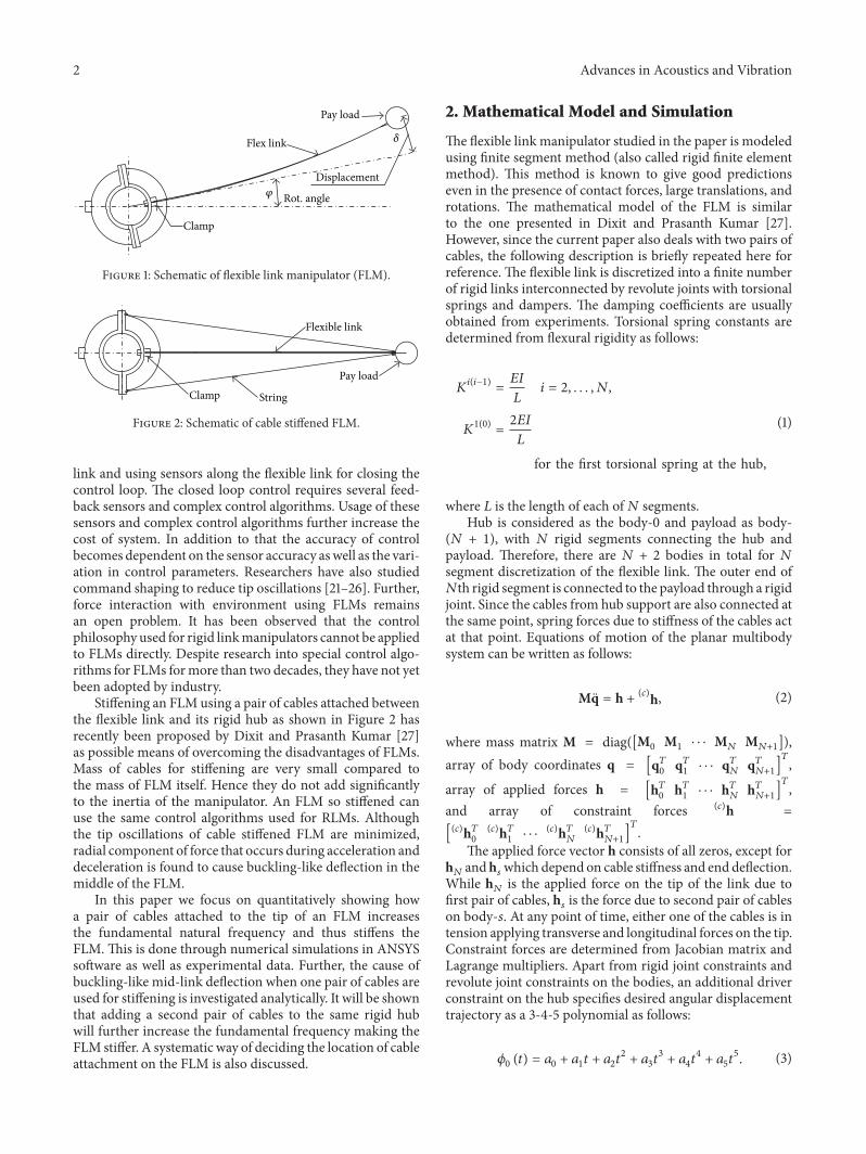
Robot manipulators used in industry spend much of theirenergies in moving their end effectors from one point toanother. Their links are designed to have very low deflectionwhich makes them bulky. Hence they are called rigid linkmanipulators (RLMs). In order to reduce wastage of energyin moving the manipulator link mass, researchers proposedflexible link manipulators (FLMs) (Figure 1) which are notonly much lighter but also highly flexible because of thereduced inertia. Moving a payload at the end effector ofFLM to desired location at the specified time requires specialcontrol algorithms designed taking into account the under-actuated nature of FLMs.
In order to minimize the tip vibration of FLMs, severalresearchers have analyzed the problem in different ways.Having amore accuratemodel helps in better control of FLM.Some researchers have focused on modeling of the flexiblearm [1–8] so as to control it effectively. Modeling of the flexi-ble arm has been studied for single [2, 6, 7] as well as multiple
flexible link systems [4]. Piedboeuf [9] presented sixmethodsto model a rotating flexible beam considering foreshorteningeffect. Sugiyama et al. [10] presented finite segment modelingof flexible link considering discrete segments. The methodexplains modeling of finite segments using torsional springsbetween adjacent segments. Kiran et al. [11] presented bondgraph technique for modeling a single link flexible spacemanipulator. Kinematic analysis of the FLM has been studiedand suitability of coordinate frame was discussed in [8].
Different methods of control to reduce or eliminatetip oscillations of FLM have been studied which includesresonant control [12], sliding mode control [13–16], optimalcontrol strategies [2], and other nonlinear control methods[17]. Morales et al. [18] studied behaviours of light weightsingle link FLMwith payload variations by using disturbanceobserver. Baroudi et al. [19] presented their study on controlof flexible manipulator using LQR technique. Ahmad andMohamed [20] compared the control performance of LQRand PID to suppress the tip vibration. Several authors haveused closed loop control methodologies by modeling flexible
Hindawi Publishing CorporationAdvances in Acoustics and VibrationVolume 2016, Article ID 4503696, 9 pageshttp://dx.doi.org/10.1155/2016/4503696
2 Advances in Acoustics and Vibration
Pay load
Flex link
Displacement𝜑 Rot. angle
Clamp
𝛿
Figure 1: Schematic of flexible link manipulator (FLM).
Pay load
Flexible link
Clamp String
Figure 2: Schematic of cable stiffened FLM.
link and using sensors along the flexible link for closing thecontrol loop. The closed loop control requires several feed-back sensors and complex control algorithms. Usage of thesesensors and complex control algorithms further increase thecost of system. In addition to that the accuracy of controlbecomes dependent on the sensor accuracy aswell as the vari-ation in control parameters. Researchers have also studiedcommand shaping to reduce tip oscillations [21–26]. Further,force interaction with environment using FLMs remainsan open problem. It has been observed that the controlphilosophy used for rigid linkmanipulators cannot be appliedto FLMs directly. Despite research into special control algo-rithms for FLMs formore than two decades, they have not yetbeen adopted by industry.
Stiffening an FLM using a pair of cables attached betweenthe flexible link and its rigid hub as shown in Figure 2 hasrecently been proposed by Dixit and Prasanth Kumar [27]as possible means of overcoming the disadvantages of FLMs.Mass of cables for stiffening are very small compared tothe mass of FLM itself. Hence they do not add significantlyto the inertia of the manipulator. An FLM so stiffened canuse the same control algorithms used for RLMs. Althoughthe tip oscillations of cable stiffened FLM are minimized,radial component of force that occurs during acceleration anddeceleration is found to cause buckling-like deflection in themiddle of the FLM.
In this paper we focus on quantitatively showing howa pair of cables attached to the tip of an FLM increasesthe fundamental natural frequency and thus stiffens theFLM. This is done through numerical simulations in ANSYSsoftware as well as experimental data. Further, the cause ofbuckling-like mid-link deflection when one pair of cables areused for stiffening is investigated analytically. It will be shownthat adding a second pair of cables to the same rigid hubwill further increase the fundamental frequency making theFLM stiffer. A systematic way of deciding the location of cableattachment on the FLM is also discussed.
2. Mathematical Model and Simulation
The flexible link manipulator studied in the paper is modeledusing finite segment method (also called rigid finite elementmethod). This method is known to give good predictionseven in the presence of contact forces, large translations, androtations. The mathematical model of the FLM is similarto the one presented in Dixit and Prasanth Kumar [27].However, since the current paper also deals with two pairs ofcables, the following description is briefly repeated here forreference. The flexible link is discretized into a finite numberof rigid links interconnected by revolute joints with torsionalsprings and dampers. The damping coefficients are usuallyobtained from experiments. Torsional spring constants aredetermined from flexural rigidity as follows:
𝐾𝑖(𝑖−1)=𝐸𝐼
𝐿𝑖 = 2, . . . , 𝑁,
𝐾1(0)=2𝐸𝐼
𝐿
for the first torsional spring at the hub,
(1)
where 𝐿 is the length of each of𝑁 segments.Hub is considered as the body-0 and payload as body-(𝑁 + 1), with 𝑁 rigid segments connecting the hub andpayload. Therefore, there are 𝑁 + 2 bodies in total for 𝑁segment discretization of the flexible link. The outer end of𝑁th rigid segment is connected to the payload through a rigidjoint. Since the cables from hub support are also connected atthe same point, spring forces due to stiffness of the cables actat that point. Equations of motion of the planar multibodysystem can be written as follows:
Mq = h + (𝑐)h, (2)
where mass matrix M = diag([M0 M1⋅ ⋅ ⋅ M
𝑁M𝑁+1]),
array of body coordinates q = [q𝑇0
q𝑇1⋅ ⋅ ⋅ q𝑇𝑁
q𝑇𝑁+1]𝑇
,
array of applied forces h = [h𝑇0
h𝑇1⋅ ⋅ ⋅ h𝑇𝑁
h𝑇𝑁+1]𝑇
,and array of constraint forces (𝑐)h =
[(𝑐)h𝑇0
(𝑐)h𝑇1⋅ ⋅ ⋅(𝑐)h𝑇𝑁
(𝑐)h𝑇𝑁+1]𝑇
.The applied force vector h consists of all zeros, except for
h𝑁andh𝑠which depend on cable stiffness and end deflection.
While h𝑁is the applied force on the tip of the link due to
first pair of cables, h𝑠is the force due to second pair of cables
on body-𝑠. At any point of time, either one of the cables is intension applying transverse and longitudinal forces on the tip.Constraint forces are determined from Jacobian matrix andLagrange multipliers. Apart from rigid joint constraints andrevolute joint constraints on the bodies, an additional driverconstraint on the hub specifies desired angular displacementtrajectory as a 3-4-5 polynomial as follows:
𝜙0 (𝑡) = 𝑎0 + 𝑎1𝑡 + 𝑎2𝑡
2+ 𝑎3𝑡3+ 𝑎4𝑡4+ 𝑎5𝑡5. (3)

Advances in Acoustics and Vibration 3
Table 1: Simulation parameters of FLM.
Parameter ValueFlexible link size 500 × 30 × 1.5Mass of link 0.175 kgMass of clamp 0.150 kgDistance of cable attachmentfrom shaft axis 70mm
Mass of payload 0.18 kg, 0.12 kg, 0.06 kgDensity of link 7800 kg/m3
Diameter of cable 0.8mmNumber of cables 1 pair and 2 pairsCable material density 7800 kg/m3
Target rotation 45 deg.Time duration 1 sec
Coefficients of this polynomial are determined from thefollowing conditions:
𝜙0 (0) = 0,
��0(0) = 0,
��0(0) = 0,
𝜙0 (1) =𝜋
4,
��0(1) = 0,
��0(1) = 0.
(4)
Table 1 lists the parameter and values used for simulation.A damping coefficient of 0.01 is found to closely match thevibration decay observed in experiments on flexible link.The results of simulations are shown in Figures 3 and 4.Without cables, the tip deflection is quite high. Using onepair of cables attached between tip and hub, deflections arebrought down to less than a millimeter. Although this mayseem reasonably small deflection, it will be shown in thenext section that this could lead to high mid-link deflectionresulting in foreshortening.
3. Deflection Analysis and CableAttachment Location
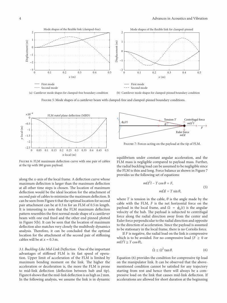
Analysis of mode shapes of a flexible link gives valuableinformation on the location of attachment of cables onthe FLM to minimize tip vibration. FLMs in clamped-freecondition will have maximum deflection at the free tip for itsfirst normal mode. This is similar to a cantilever beam whichhas maximum deflection at the free end. Figure 5(a) showsthe first and second normal modes of a cantilever beam.For the given smooth trajectory input, first normal mode ismore prominent than the second normal mode. Therefore,the location of attachment of the first pair of cables will beat the tip. With this attachment at the tip resisting the tip
180 g120 g60 g
−100
−50
0
50
100
Tip
disp
lace
men
t (m
m)
0.5 1 1.5 20Time (s)
Figure 3: FLM tip deflection without cables for various payloads.
−0.4
−0.2
0
0.2
0.4
Tip
defle
ctio
n (m
m)
0.5 1 1.5 20Time (s)
180 g120 g60 g
Figure 4: FLM tip deflection with one pair of cables for variouspayloads.
deflection, the flexible link will behave similar to a clamped-pinned beam rather than a clamped-free beam. Figure 5(b)shows the normal mode shapes of a cantilever beam with thenew clamped-pinned boundary condition.
It should be noted that the behavior of FLM with the firstpair of cables will be similar to that of a cantilever beam withthe end pinned but will not be identical. It is because a pinnedjoint does not allow translation in any directionwhereas cableattachment does allow translation consistent with the con-straints imposed by both cables. For this reason, we also tryto validate the results of maximumdeflection withmultibodydynamics simulation and mode analysis through ANSYSsimulation which are closer to the actual physical model.
After attachment of the first pair of cables, multibodydynamics analysis as described in previous section for anFLM with one pair of cables at the tip has been carriedout for the one second trajectory in (3). For each time step,deflection of the FLM in local frame (attached at the hub ofthe FLM) with respect to the coordinate along its length hasbeen obtained from simulation. At each time step there willbe a deflection curve withmaximumdeflection at some point
4 Advances in Acoustics and Vibration
Mode shapes of the flexible link (clamped-free)
First modeSecond mode
−3
−2
−1
0
1
2
Disp
lace
men
t (m
)
0.1 0.2 0.3 0.4 0.50x (m)
(a) Cantilever mode shapes for clamped-free boundary condition
Mode shapes of the flexible link for clamped-pinned
First modeSecond mode
−2
−1
0
1
2
Disp
lace
men
t (m
)
0.1 0.2 0.3 0.4 0.50x (m)
(b) Cantilever mode shapes for clamped-pinned boundary condition
Figure 5: Mode shapes of a cantilever beam with clamped-free and clamped-pinned boundary conditions.
FLM outof plane deflection (MBD)×10−4
−2.5
−2
−1.5
−1
−0.5
0
y-lo
cal (
m)
0.05 0.1 0.15 0.2 0.25 0.3 0.35 0.4 0.45 0.50x-local (m)
Figure 6: FLM maximum deflection curve with one pair of cablesat the tip with 180 gram payload.
along the 𝑥-axis of the local frame. A deflection curve whosemaximum deflection is larger than the maximum deflectionat all other time steps is chosen. The location of maximumdeflection would be the ideal location for the attachment ofsecond pair of cables tominimize themaximumdeflection. Itcan be seen fromFigure 6 that the optimal location for secondpair attachment can be at 0.3m for an FLM of 0.5m length.It is interesting to note that the FLM maximum deflectionpattern resembles the first normal mode shape of a cantileverbeam with one end fixed and the other end pinned plottedin Figure 5(b). It can be seen that the location of maximumdeflection also matches very closely the multibody dynamicsanalysis. Therefore, it can be concluded that the optimallocation for the attachment of the second pair of stiffeningcables will be at 𝑥 = 0.3m.
3.1. Buckling-Like Mid-Link Deflection. One of the importantadvantages of stiffened FLM is its fast speed of opera-tion. Upper limit of acceleration of the FLM is limited bymaximum bending moment on the link. The higher theacceleration or deceleration is, the more the FLM is proneto mid-link deflection (deflection between hub and tip).Figure 6 shows that themid-link deflection is as high as 2mm.In the following analysis, we assume the link is in dynamic
Centrifugal force
Euler force
Tension T
m Ωl
F
mΩ2l𝜃𝜙0(t)
Figure 7: Forces acting on the payload at the tip of FLM.
equilibrium under constant angular acceleration, and theFLM mass is negligible compared to payload mass. Further,the radial buckling load can be assumed to be negligible sincethe FLM is thin and long. Force balance as shown in Figure 7provides us the following set of equations:
𝑚Ω2𝑙 − 𝑇 cos 𝜃 = 𝐹,
𝑚Ω𝑙 = 𝑇 sin 𝜃,(5)
where 𝑇 is tension in the cable, 𝜃 is the angle made by thecable with the FLM, 𝐹 is the net horizontal force on thepayload in the local frame, and Ω = ��
0(𝑡) is the angular
velocity of the hub. The payload is subjected to centrifugalforce along the radial direction away from the center andEuler force perpendicular to the radial direction and oppositeto the direction of acceleration. Since the payload is assumedto be stationary in the local frame, there is no Coriolis force.
If 𝐹 is negative, the radial load on the link is compressivewhich is to be avoided. For no compressive load (𝐹 ≥ 0 or𝑚Ω2𝑙 ≥ 𝑇 cos 𝜃),
Ω ≤ Ω2 tan 𝜃. (6)
Equation (6) provides the condition for compressive tip loadon the manipulator link. It can be observed that the above-mentioned condition cannot be satisfied for any trajectorystarting from rest and hence there will always be a com-pressive load on the link that causes mid-link deflection. Ifaccelerations are allowed for short duration at the beginning
Advances in Acoustics and Vibration 5
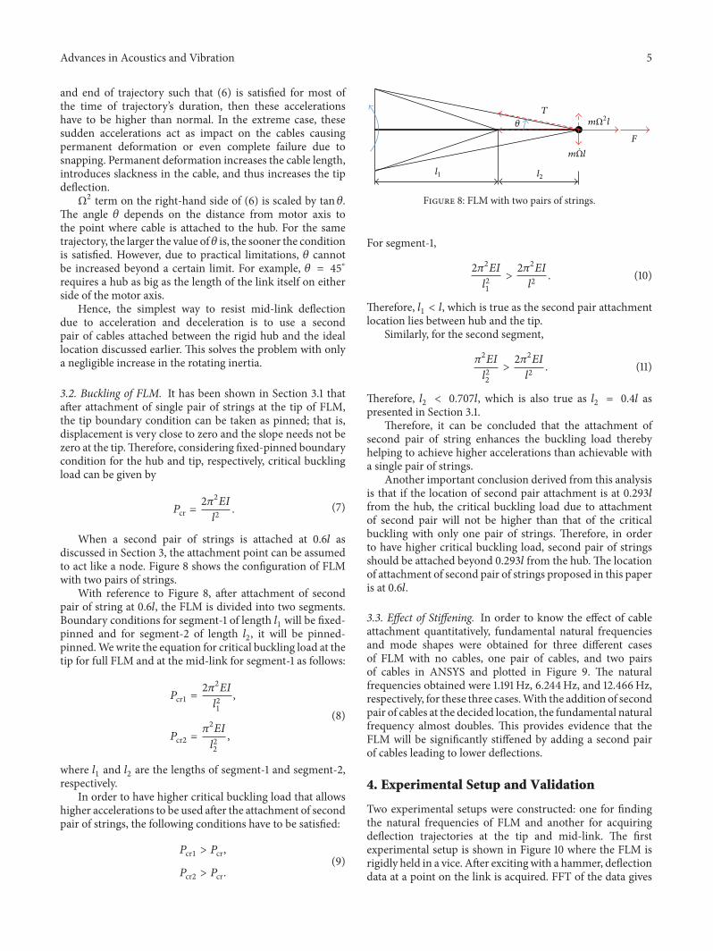
and end of trajectory such that (6) is satisfied for most ofthe time of trajectory’s duration, then these accelerationshave to be higher than normal. In the extreme case, thesesudden accelerations act as impact on the cables causingpermanent deformation or even complete failure due tosnapping. Permanent deformation increases the cable length,introduces slackness in the cable, and thus increases the tipdeflection.Ω2 term on the right-hand side of (6) is scaled by tan 𝜃.
The angle 𝜃 depends on the distance from motor axis tothe point where cable is attached to the hub. For the sametrajectory, the larger the value of 𝜃 is, the sooner the conditionis satisfied. However, due to practical limitations, 𝜃 cannotbe increased beyond a certain limit. For example, 𝜃 = 45∘requires a hub as big as the length of the link itself on eitherside of the motor axis.
Hence, the simplest way to resist mid-link deflectiondue to acceleration and deceleration is to use a secondpair of cables attached between the rigid hub and the ideallocation discussed earlier. This solves the problem with onlya negligible increase in the rotating inertia.
3.2. Buckling of FLM. It has been shown in Section 3.1 thatafter attachment of single pair of strings at the tip of FLM,the tip boundary condition can be taken as pinned; that is,displacement is very close to zero and the slope needs not bezero at the tip.Therefore, considering fixed-pinned boundarycondition for the hub and tip, respectively, critical bucklingload can be given by
𝑃cr =2𝜋2𝐸𝐼
𝑙2. (7)
When a second pair of strings is attached at 0.6𝑙 asdiscussed in Section 3, the attachment point can be assumedto act like a node. Figure 8 shows the configuration of FLMwith two pairs of strings.
With reference to Figure 8, after attachment of secondpair of string at 0.6𝑙, the FLM is divided into two segments.Boundary conditions for segment-1 of length 𝑙
1will be fixed-
pinned and for segment-2 of length 𝑙2, it will be pinned-
pinned.Wewrite the equation for critical buckling load at thetip for full FLM and at the mid-link for segment-1 as follows:
𝑃cr1 =2𝜋2𝐸𝐼
𝑙2
1
,
𝑃cr2 =𝜋2𝐸𝐼
𝑙2
2
,
(8)
where 𝑙1and 𝑙2are the lengths of segment-1 and segment-2,
respectively.In order to have higher critical buckling load that allows
higher accelerations to be used after the attachment of secondpair of strings, the following conditions have to be satisfied:
𝑃cr1 > 𝑃cr,
𝑃cr2 > 𝑃cr.(9)
T
𝜃
l1 l2
m Ωl
F
mΩ2l
Figure 8: FLM with two pairs of strings.
For segment-1,
2𝜋2𝐸𝐼
𝑙2
1
>2𝜋2𝐸𝐼
𝑙2. (10)
Therefore, 𝑙1< 𝑙, which is true as the second pair attachment
location lies between hub and the tip.Similarly, for the second segment,
𝜋2𝐸𝐼
𝑙2
2
>2𝜋2𝐸𝐼
𝑙2. (11)
Therefore, 𝑙2< 0.707𝑙, which is also true as 𝑙
2= 0.4𝑙 as
presented in Section 3.1.Therefore, it can be concluded that the attachment of
second pair of string enhances the buckling load therebyhelping to achieve higher accelerations than achievable witha single pair of strings.
Another important conclusion derived from this analysisis that if the location of second pair attachment is at 0.293𝑙from the hub, the critical buckling load due to attachmentof second pair will not be higher than that of the criticalbuckling with only one pair of strings. Therefore, in orderto have higher critical buckling load, second pair of stringsshould be attached beyond 0.293𝑙 from the hub. The locationof attachment of second pair of strings proposed in this paperis at 0.6𝑙.
3.3. Effect of Stiffening. In order to know the effect of cableattachment quantitatively, fundamental natural frequenciesand mode shapes were obtained for three different casesof FLM with no cables, one pair of cables, and two pairsof cables in ANSYS and plotted in Figure 9. The naturalfrequencies obtained were 1.191Hz, 6.244Hz, and 12.466Hz,respectively, for these three cases.With the addition of secondpair of cables at the decided location, the fundamental naturalfrequency almost doubles. This provides evidence that theFLM will be significantly stiffened by adding a second pairof cables leading to lower deflections.
4. Experimental Setup and Validation
Two experimental setups were constructed: one for findingthe natural frequencies of FLM and another for acquiringdeflection trajectories at the tip and mid-link. The firstexperimental setup is shown in Figure 10 where the FLM isrigidly held in a vice. After exciting with a hammer, deflectiondata at a point on the link is acquired. FFT of the data gives

6 Advances in Acoustics and Vibration
DisplacementSTEP = 1SUB = 1FREQ = 1.191DMX = 5.313 Y
XZ
1
(a) First normal mode of FLM without cables
DisplacementSTEP = 1SUB = 1FREQ = 6.244DMX = 3.968 Y
XZ
1
(b) First normal mode of FLM with one pair of cables
DisplacementSTEP = 1SUB = 1FREQ = 12.466DMX = 4.615
Y
XZ
1
(c) First normal mode of FLM with two pairs of cables
Figure 9: Modal analysis in ANSYS.
Figure 10: Experimental setup for finding natural frequencies forone pair of cables.
the natural frequency.The experiment was repeated for threecases: FLM without cables, FLM with one pair of cables, andFLMwith two pairs of cables.The purpose of this experimentis to qualitatively see how much one and two pairs of cablesstiffen the FLM.
Figure 11 shows the FFT of FLM deflection data fromexperiments for three cases. The fundamental natural fre-quencies obtained are 1.356Hz, 6.66Hz, and 12.31Hz, respec-tively. These fundamental natural frequencies shown by FFTplots closely match those obtained from ANSYS.
The second experimental setup consists of a DC servomotor, power supply, FLM, cables, two displacement sensors,an attachment for mounting displacement sensors, a dataacquisition system, and a computer. The DC servo motoris a 100 watt Dynamixel Pro servo H54-100-S500-R whichcan accept position commands over RS485 communicationlink from the computer. FLM is mounted on the motor
shaft by means of a rigid hub. The attachment for mountingdisplacement sensors is a rigid manipulator arm attachedto the same hub and parallel to the FLM in undeflectedcondition.
Unlike the setup discussed in Dixit and Prasanth Kumar[27] where deflection is measured only at the end of thetrajectory, deflection in local frame can be measured withthe current setup throughout the trajectory.The two displace-ment sensors are noncontact laser based sensors opto-NCDT1402 with a range of 50mm to 150mm and a resolution of 10microns.The sensor outputs are analog which are acquired bya data acquisition system at 1 kHz from which deflection datais obtained. The DC servo motor has digital output pins, oneof which is connected to data acquisition system.This outputpin, which is usually held low, is triggered to high at thebeginning of trajectory command received from computerand held low again from the end of trajectory. The input andoutput data are time synced using this trigger. The schematicof experimental setup and photograph of cable stiffened FLMare shown in Figures 12(a) and 12(b), respectively. Note thatdue to difficulty in measuring deflection exactly at the tipwhere the payload is attached, deflection close to the tip ismeasured as tip deflection.When comparing with simulationresults, deflection of the corresponding point in simulationmodel is considered tip deflection.
Experiments were conducted with 180 gram payload anddeflection at tip and mid-link (where second pair of cablesare attached) was measured. Figures 13 and 14 show thesimulation and experimental results of FLM deflections with

Advances in Acoustics and Vibration 7
0
1000
2000
3000
Without string (FFT)
1 2 3 4 50Frequency (Hz)
(a) FFT of FLM without cables
0
1000
2000
3000With one pair of string (FFT)
1 2 3 4 5 6 7 80Frequency (Hz)
(b) FFT of FLM with one pair of cables
0
1000
2000
3000With two pairs of string (FFT)
5 10 150Frequency (Hz)
(c) FFT of FLM with two pairs of cables
Figure 11: FFT of FLM deflection data for three cases.
DAQmonitor
Actuatorcontroller
Junction box
Data acq.system
Non-contactsensor
(a) Schematic of experimental setup of cable stiffened FLM
(b) Experimental setup for one pair of cables
Figure 12: Experimental setup of cable stiffened FLM.

8 Advances in Acoustics and Vibration
0 0.5 1 1.5 2−0.4
−0.2
0
0.2
0.4
MidTip
Time (s)
Tip
disp
lace
men
t (m
m)
FLM tip motion with one pair (PL = 180 g)
Figure 13: Simulation results of tip andmid-link deflections for onepair of cables.
TipMidActuator pulse
−2
0
2
4
6
FLM
defl
ectio
n (m
m)
1 2 3 4 50Time (s)
FLM deflection with single pair at tip, PL = 180 g
Figure 14: Experimental results of tip and mid-link deflections forone pair of cables.
TipMid
−0.05
0
0.05
Defl
ectio
n (m
m)
0.5 1 1.5 20Time (s)
FLM deflection with two pairs, PL = 180 g
Figure 15: Simulation results of tip andmid-link deflections for twopairs of cables.
one pair of cables attached at the tip, respectively. Similarly,Figures 15 and 16 show the simulation and experimentalresults of FLM deflections with two pairs of cables, respec-tively. The actuator pulse shown in experimental resultsindicate the duration of trajectory command.
Comparing the simulation and experimental results, it isclear that addition of second pair of cables in fact reduces
TipMidActuator pulse
−1−0.5
00.5
11.5
2
FLM
defl
ectio
n (m
m)
4 4.5 5 5.5 63.5Time (s)
FLM deflection with two pairs, PL = 180 g
Figure 16: Experimental results of tip and mid-link deflections fortwo pairs of cables.
the deflection at both the tip and the mid-link. However,deflections occurring during experiments are about one orderof magnitude higher than those of simulation results andhigher frequency components also appear. As a first guess,we believed that the discrepancy was due to the presence ofslackness in the cables allowing the deflections to increase.Even when we tried to reduce the slackness by introducing asmall pretension in the cables, results were similar. Anotherpossibility is the presence of small bends in the steel cablesconnecting the link to the rigid hub. These bends act ascurved beams with low bending stiffness compared to theaxial stiffness of the cable. We theorize that when the payloadis subjected to inertia forces during the link motion, lowstiffness, till the bend opens up completely, causes connectedpoints on the link to deflect significantly. This is a majorlimitation of cable stiffening method.
5. Conclusions
It is known that any flexible body has infinity degrees offreedom. Therefore, ideally a single input at the hub willnot be able to track arbitrary trajectories of FLMs makingthem underactuated systems. As the interest is to restrictoscillations of the tip alone, the methodology presented inthis paper attempts to restrict DOFs of the tip by attachmentof cables. A systematic way is presented for the attachmentof cables to minimize link deflections. Foreshortening effectdue to mid-link deflection gets minimized by attachment ofadditional pairs of cables at the specified locations. Two sets ofexperimental setupswere constructed. It is concluded that thesimulation results and experimental results have very goodagreement as far as the fundamental natural frequencies areconcerned.
Trajectories obtained from second experimental setupshow one order of magnitude discrepancy with simulationresults, although the trend of reduced deflectionwith increasein the number of pairs of cables is present. The majorlimitation of large deflections found in experiments maybe overcome by more accurate fabrication and assembly ofcables on the FLM.

Advances in Acoustics and Vibration 9
Competing Interests
The authors declare that there is no conflict of interestsregarding the publication of this paper.
Acknowledgments
Thisworkwas supported by the project “Cable Stiffened Flex-ible Link Manipulator for Pick-and-Place Tasks” (YSS/2014/000010) sponsored by Department of Science and Technol-ogy, Government of India.
References
[1] R. H. Cannon Jr. and E. Schmitz, “Initial experiments on theend-point control of a flexible one-link robot,”The InternationalJournal of Robotics Research, vol. 3, no. 3, pp. 62–75, 1984.
[2] W. D. Zhu and C. D. Mote Jr., “Dynamic modeling and optimalcontrol of rotating Euler-Bernoulli beams,” Journal of DynamicSystems, Measurement and Control, vol. 119, no. 4, pp. 802–808,1997.
[3] M.H. Korayem,H.N. Rahimi, andA.Nikoobin, “Mathematicalmodeling and trajectory planning of mobile manipulators withflexible links and joints,” Applied Mathematical Modelling, vol.36, no. 7, pp. 3229–3244, 2012.
[4] W. Chen, “Dynamic modeling of multi-link flexible roboticmanipulators,” Computers & Structures, vol. 79, no. 2, pp. 183–195, 2001.
[5] A. Fenili and J. M. Balthazar, “The rigid-flexible nonlinearrobotic manipulator: modeling and control,” Communicationsin Nonlinear Science and Numerical Simulation, vol. 16, no. 5,pp. 2332–2341, 2011.
[6] M. Khairudin, “Dynamic modelling of a flexible link manipu-lator robot using AMM,” TELKOMNIKA Indonesian Journal ofElectrical Engineering, vol. 6, no. 3, pp. 185–190, 2008.
[7] S. Bosnjak and N. Zrnic, “On the dynamic modelling of exiblemanipulators,” FME Transactions, vol. 34, pp. 231–237, 2006.
[8] A. A. Ata, E. H. Haraz, A. E. A. Rizk, and S. N. Hanna,“Kinematic analysis of a single link flexiblemanipulator,” inPro-ceedings of the IEEE International Conference on Industrial Tech-nology (ICIT ’12), pp. 852–857, Athens, Greece, March 2012.
[9] J.-C. Piedboeuf, “Six methods to model a flexible beam rotatingin the vertical plane,” in Proceedings of the IEEE InternationalConference on Robotics and Automation (ICRA ’01), vol. 3, pp.2832–2839, IEEE, Seoul, Republic of Korea, May 2001.
[10] H. Sugiyama, N. Kobayashi, and Y. Komaki, “Modeling andexperimental methods for dynamic analysis of the spaghettiproblem,” Journal of Vibration and Acoustics, vol. 127, no. 1, pp.44–51, 2005.
[11] G. S. Kiran, A. Kumar, P. M. Pathak, and N. Sukavanam,“Trajectory control of flexible space robot,” in Proceedings of theIEEE International Conference onMechatronics and Automation(ICMA ’08), pp. 738–743, IEEE, Takamatsu, Japan, August 2008.
[12] I. A. Mahmood, S. O. R. Moheimani, and B. Bhikkaji, “Precisetip positioning of a flexiblemanipulator using resonant control,”IEEE/ASME Transactions on Mechatronics, vol. 13, no. 2, pp.180–186, 2008.
[13] V. Etxebarria, A. Sanz, and I. Lizarraga, “Control of a lightweightflexible robotic arm using sliding modes,” International Journalof Advanced Robotics, vol. 2, no. 2, pp. 103–110, 2005.
[14] G. Mamani, J. M. A.-D. Silva, and V. Feliu-Batlle, “Least squaresstate estimator based sliding mode control of a very lightweightsingle-link flexible robot arm,” in Proceedings of the IEEE 2009International Conference on Mechatronics (ICM ’09), pp. 1–6,IEEE, Malaga, Spain, April 2009.
[15] R. Fareh, M. Saad, and M. Saad, “Adaptive control for asingle flexible link manipulator using sliding mode technique,”in Proceedings of the 6th International Multi-Conference onSystems, Signals and Devices (SSD ’09), pp. 1–6, IEEE, Djerba,Tunisia, March 2009.
[16] S. Kurode and P. Dixit, “Output feedback control of flexible linkmanipulator using sliding modes,” in Proceedings of the 20127th International Conference on Electrical and Computer Engi-neering (ICECE ’12), pp. 949–952, IEEE, Dhaka, Bangladesh,December 2012.
[17] S. S. Ge, T. H. Lee, and G. Zhu, “A nonlinear feedback controllerfor a single-link flexible manipulator based on a finite elementmodel,” Journal of Robotic Systems, vol. 14, no. 3, pp. 165–178,1997.
[18] R. Morales, V. Feliu, and V. Jaramillo, “Position control of verylightweight single-link flexible arms with large payload varia-tions by using disturbance observers,”Robotics andAutonomousSystems, vol. 60, no. 4, pp. 532–547, 2012.
[19] M. Baroudi, M. Saad, and W. Ghie, “State-feedback and linearquadratic regulator applied to a single-link flexible manipula-tor,” in Proceedings of the 2009 IEEE International Conferenceon Robotics and Biomimetics (ROBIO ’09), pp. 1381–1386, IEEE,Guilin, China, December 2009.
[20] M. A. Ahmad and Z. Mohamed, “Techniques of vibrationand end-point trajectory control of flexible manipulator,” inProceedings of the 6th International Symposium onMechatronicsand its Applications (ISMA ’09), pp. 1–6, IEEE, Sharjah, UnitedArab Emirates, March 2009.
[21] H. Yang, M. H. Ang Jr., and H. Krishnan, “Control of a tip-loaded flexible-link robot using shaped input command,” inProceedings of the American Control Conference (ACC ’98), vol.5, pp. 3075–3076, IEEE, Philadelphia, Pa, USA, June 1998.
[22] W. Chatlatanagulchai, V. M. Beazel, and P. H. Meckl, “Com-mand shaping applied to a flexible robot with configuration-dependent resonance,” in Proceedings of the American ControlConference, IEEE, Minneapolis, Minn, USA, June 2006.
[23] K.-P. Liu and Y.-C. Li, “Vibration suppression for a class offlexible manipulator control with input shaping technique,” inProceedings of the International Conference onMachine Learningand Cybernetics, pp. 835–839, August 2006.
[24] K.-P. Liu, “Experimental evaluation of preshaped inputs toreduce vibration for flexible manipulator,” in Proceedings of the6th International Conference on Machine Learning and Cyber-netics (ICMLC ’07), vol. 4, pp. 2411–2415, IEEE, Hong Kong,August 2007.
[25] M. Romano, B. N. Agrawal, and F. Bernelli-Zazzera, “Exper-iments on command shaping control of a manipulator withflexible links,” Journal of Guidance, Control, and Dynamics, vol.25, no. 2, pp. 232–239, 2002.
[26] N. Seth and K. S. Rattan, “Vibration control of flexible manip-ulators,” in Proceedings of the IEEE National Aerospace andElectronics Conference (NAECON ’92), pp. 876–882, 1992.
[27] R. Dixit and R. Prasanth Kumar, “Cable stiffened flexiblelink manipulator,” in Proceedings of the IEEE/RSJ InternationalConference on Intelligent Robots and Systems (IROS ’14), pp. 871–876, Chicago, Ill, USA, September 2014.

International Journal of
AerospaceEngineeringHindawi Publishing Corporationhttp://www.hindawi.com Volume 2014
RoboticsJournal of
Hindawi Publishing Corporationhttp://www.hindawi.com Volume 2014
Hindawi Publishing Corporationhttp://www.hindawi.com Volume 2014
Active and Passive Electronic Components
Control Scienceand Engineering
Journal of
Hindawi Publishing Corporationhttp://www.hindawi.com Volume 2014
International Journal of
RotatingMachinery
Hindawi Publishing Corporationhttp://www.hindawi.com Volume 2014
Hindawi Publishing Corporation http://www.hindawi.com
Journal ofEngineeringVolume 2014
Submit your manuscripts athttp://www.hindawi.com
VLSI Design
Hindawi Publishing Corporationhttp://www.hindawi.com Volume 2014
Hindawi Publishing Corporationhttp://www.hindawi.com Volume 2014
Shock and Vibration
Hindawi Publishing Corporationhttp://www.hindawi.com Volume 2014
Civil EngineeringAdvances in
Acoustics and VibrationAdvances in
Hindawi Publishing Corporationhttp://www.hindawi.com Volume 2014
Hindawi Publishing Corporationhttp://www.hindawi.com Volume 2014
Electrical and Computer Engineering
Journal of
Advances inOptoElectronics
Hindawi Publishing Corporation http://www.hindawi.com
Volume 2014
The Scientific World JournalHindawi Publishing Corporation http://www.hindawi.com Volume 2014
SensorsJournal of
Hindawi Publishing Corporationhttp://www.hindawi.com Volume 2014
Modelling & Simulation in EngineeringHindawi Publishing Corporation http://www.hindawi.com Volume 2014
Hindawi Publishing Corporationhttp://www.hindawi.com Volume 2014
Chemical EngineeringInternational Journal of Antennas and
Propagation
International Journal of
Hindawi Publishing Corporationhttp://www.hindawi.com Volume 2014
Hindawi Publishing Corporationhttp://www.hindawi.com Volume 2014
Navigation and Observation
International Journal of
Hindawi Publishing Corporationhttp://www.hindawi.com Volume 2014
DistributedSensor Networks
International Journal of