research article simulation of impinging cooling...
TRANSCRIPT

Research ArticleSimulation of Impinging Cooling Performance with Pin Finsand Mist Cooling Adopted in a Simplified Gas TurbineTransition Piece
Tao Xu Hang Xiu Junlou Li Haichao Ge Qing Shao Guang Yang and Zhenglei Yu
College of Mechanical Science amp Engineering Jilin University Changchun 130025 China
Correspondence should be addressed to Zhenglei Yu yuzhengleihotmailcom
Received 6 December 2013 Accepted 27 January 2014 Published 9 March 2014
Academic Editor Raseelo Joel Moitsheki
Copyright copy 2014 Tao Xu et al This is an open access article distributed under the Creative Commons Attribution License whichpermits unrestricted use distribution and reproduction in any medium provided the original work is properly cited
The gas turbine transition piece was simplified to a one-four cylinder double chamber model with a single row of impinging holesin the outer wall Heat transfer augmentation in the coolant chamber was achieved through the use of pin fin structure and mistcooling which could increase the turbulence and heat transfer efficiency The present research is focused on heat transfer andpressure characteristics of the impinging cooling in the coolant chamber using FLUENT software With the given diameter ofimpinging hole pin fin diameter ratios 119863119889 have been numerically studied in ranges from 1 to 2 Three different detached 119871
were simulated The impinging cooling performance in all cases was compared between single-phase and two-phase (importedappropriate mist) flow in the coolant chamber All the simulation results reveal that the factors of 119871 and119863119889 have significant effectson the convective heat transfer After the pin fin structurewas taken the resulting temperature decrease of 3877 K atmost comparedwith the result of structure without pin fins And with the mist injecting into the cooling chamber the area weighted averagetemperature got a lower value without excess pressure loss which could satisfy the more stringent requirements in engineering
1 Introduction
Low installation cost and higher output have made gasturbine a popular power plant in the modern industries Gasturbines have been widely used in the domain of aerospaceand ship propulsion for more than half a century Tomeet theincreasing requirement of power research and improvementof heat efficiency of gas turbines have become the hottestresearch focus To improve the thermal efficiency and outputof gas turbines the temperature of working fluid is usuallyelevated higher than the metal melting Spontaneously thecomponents of gas turbine such as combustion chambercombustor transition pieces and turbine blades need tobe protected from the high temperature gas by coolingtechnology A wide variety of cooling technologies includingfilm cooling and impinging cooling have been successfullyused in cooling of these hot components for a few decades
Impinging jets are used in many applications for provid-ing high heatmass transfer rates Compared to other heat ormass transfer arrangements that do not employ phase changethe jet impingement device offers efficient use of the fluid and
high transfer rates In turbine applications jet impingementmay be used to cool several different sections of the enginesuch as the combustor case turbine caseliner and the criticalhigh temperature turbine blades [1] also the transition pieceused this cooling method mostly General applications andperformance of impinging jets had been discussed in anumber of reviews [2ndash4] The jet impingement angle hasan effect on heat transfer and was studied frequently [2 3]Besides some other parameters also have important effectson the impinging characteristics Dano et al [5] researchedthe effects of nozzle geometry on the flow characteristics andheat transfer performance Cheong et al [6] experimentallymeasured local heat transfer coefficients under an impingingjet with low nozzle-to-plate 119911119889 and spacings
Meanwhile pin fin cooling is often employed to protectthe hot sections from thermal degradation while extendingthe durability It is a commonly used method in the trailingedge of the gas turbine blades andmany channel flows [7ndash10]Horbach et al [8] describe an experimental study on trailingedge film cooling using coolant ejection The experimentaltest investigated the effects of different pin fins geometric
Hindawi Publishing CorporationAdvances in Mathematical PhysicsVolume 2014 Article ID 327590 11 pageshttpdxdoiorg1011552014327590
2 Advances in Mathematical Physics
configurations and the result shows that the elliptic pin finshave a strong effect on discharge behavior as well as oncooling effectiveness and heat transfer
In the literature [9 10] experimental and numericalstudies of heat transfer performance in channels with pin finswere conducted by airThe results show that the channelswithpin fins had a heat transfer coefficient that was twice that ofthe channels without pin fins The numerical computationsshowed the same trends as experimentally observed by theheat transfer enhancement through pin fin structure adoptedHeat transfer from pin fin parameters is a subject of highimportance with many engineering applications
Most of the above works are based on geometric param-eters of the cooling structure in real applications newcooling techniques are anotherway to get enhancement of theconventional impinging cooling Wang and Li [11] proposeda promising technology to enhance air film cooling with mist(small water droplets) injection Each droplet plays the partof cooling sink and it flies a distance before it completelyvaporizes And the droplet evaporation plays an importantrole in reducing the temperature near the hot wall
Li and Wang [12] conducted their first numerical simu-lations of airmist film cooling They showed that injectingsome appropriate mist in the air could enhance the coolingeffectiveness to about 30ndash50 After that they [13] continueda more fundamental study on investigating the effect ofvarious models on the computational results including theturbulence models dispersed phase modeling and differentforces models (Saffman thermophoresis and Brownian)
Whereas all the studies mentioned above about mistcooling focus on film cooling style and the previous litera-tures about impinging cooling and pin fin cooling structuremainly focus on gas turbine blades structure electronicequipment and many other channel flow Although Yu et al[14] introduce the mist into impinging cooling technologythe cooling structure does not contain pin fin structureAnd those literatures about pin fins focus on some pinfin structures such as cross-sectional shape detached spacebetween the pin tip and the end wall which is a limited workabout the impinging characteristics through combining pinfin structures mist cooling and impingement
Based on the aforementioned cooling structure and mistfilm cooling mechanisms limited work is given to investigatethe impinging cooling performance in this study A modelof a one-fourth cylinder is designed which could simplifythe impinging structure and performance used in gas turbinetransition pieceThe objective of this paper is to useCFD sim-ulation to investigate impinging cooling performance withpin fin importing to the coolant chamber Two significanteffect factors in combination with impinging cooling and pinfin structure were investigated using numerical simulationsAll the cases were simulated in two situations one is only airin the coolant and another is air with mist together in thecooling chamber which is helpful in getting a better coolingeffectiveness
Accordingly the main objectives of the investigation areas follows (1) 119863119889 analysis with the given diameter ofimpinging hole 119889 = 1026mm pin fin diameter ratio 119863119889has been numerically studied in three different values 1 15
and 2 (2) Detached space analysis three different detachedspaces from pin fin array to impinging hole array (mark as119871 = 34 51 and 68mm) were simulated (3) Comparison ofresults the temperature of the inner wall cooling effective-ness and contours of velocity in different cases (4) Discussthe impinging cooling performance between single-phaseand two-phase flow in the cooling chamber with importappropriate mist (small droplets) into the coolant (air)
2 Numerical Model
21 Geometric Configuration The transition piece was sim-plified to a one-fourth cylinder which could simulate thetransition piecersquos structure and performance [15 16] Thediscrete coolant jets forming a protective film chamber onthe side of transition piece are drawn from the upstreamcompressor in an operational gas turbine engineThe coolantflows fed through internal passages with surface holesFrom the supply plenum the coolants ejected through threediscrete impinging holes over the external boundary layeragainst the local high thermal conduction on the other sideof the transition piece In the downstream of these impingingholes three pin fins were brought into the cooling chamber Aschematic diagram of the flow domain along with boundaryconditions and dimensions is given in Figure 1
As shown in the figure the one-fourth cylindermodel hastwo layers of chambers with a length of 1050mm and theouter chamber is right the domain full of coolant which isour major research object The dimensions of the chambersare respectively defined as an outer radius and an innerradius of 200mm and 162mm In the diagram one side ofthe coolant chamber is closed contrarily both sides of themainstream chamber as the inner chamber are opened inwhich gas could flow through from one side to the otherThe three holes distributed uniformly in one row along thecircumferential direction in the surface of the outer wall Thedistance between holes and the pin fins ismarked as a variableparameter 119871 The diameter of all the impinging holes is about1026mm that is 119889 = 1026mm Three groups of pin findiameter ratio 119863119889 (where 119863 means pin fin diameter) havebeen constituted which is set to be 1 15 and 2
22 Numerical Method
221 Governing Equations The present impinging and pinfin cooling study involves a flow which is steadied Newto-nian three-dimensional incompressible and turbulent Forsolving this state of fluid mass energy and species transportequations need to be solvedThe continuity momentum andenergy equations are given by [16]
120597
120597119909119894
(120588119906119894) = 0
120597
120597119909119894
(120588119906119894119906119895) = 120588 119892
119894minus120597119875
120597119909119894
+
120597120591119894119895
120597119909119895
+ 119865119894
120588 (119906119894
120597119890
120597119909119894
) = minus120597
120597119909119896
(minus119896120597119879
120597119909119896
) minus 119875120597119906119896
120597119909119896
+ 120593
(1)
Advances in Mathematical Physics 3
1050
525
162 38
Coolant outlet
Mainstream inlet
Inner wall
Mainstreamoutlet
Outer wall
Closed
uniform
Coolant inlet3 times empty1026(d)
Pin fins empty = D
L Y
X
Z
(a)
Coolant inlet
Mainstream inletMainstream outlet Mainstream
Coolant outletClosed
Inner wall Coolant flow
Outer wall Pin fin
XY
Z
(b)
Figure 1 Computational domain showing boundary conditions
where 119875 is the total pressure 120591119894119895is the stress tensor 120588 119892
119894and
119865119894are the gravitational body force and external body forces
120593 is the viscous heating dissipation and the heat flux is givenby Fourierrsquos law
222 Turbulence Model A wide used turbulence model isthe realizable 119896-120576 turbulence model which is a relativelyrecent development model The term ldquorealizablerdquo means thatthe model satisfies certain mathematical constraints on theReynolds stresses consistent with the physics of turbulentflows [17] The benefit of selecting this model is that it moreaccurately predicts the spreading rate of jets and it alsoprovides superior performance for rotation separation andrecirculation flows In this model the 119896 equation is the sameas in RNG model however 119862
120583is not a constant and varies as
a function of mean velocity field and turbulence (009 in log-layer of 119878 (119896120576) = 33 and 005 in shear layer of 119878(119896120576) = 6)The equation is based on a transport equation for the mean-square vorticity fluctuation [18] as follows
120588119863120576
119863119905=
120597
120597119909119895
[(120583 +120583119905
120590)120597120576
120597119909119895
] + 1198621119878120588120576 minus 119862
2
1205881205762
119896 + radicV119890 (2)
where 1198621= max[043 120578(120578 + 1)] and 119862
2= 10 This model
is used with standard wall functions to predict flow structureand heat transfer over the inner wall cooling surface
223 Dispersed-Phase ModelWater Droplets (Mist) Basedon the Newtonrsquos second law the droplet trajectory is tracedby
119898119901
119889V119901
119889119905= Σ119865 (3)
where119898119901is the dropletmass and V
119901is the droplet velocityΣ119865
is the combined force on the droplet particle which normallyincludes the hydrodynamic drag gravity and other forces
The energy balance for any individual droplet can be givenas the following equation
119898119901119888119901
119889119879
119889119905= 1205871198892ℎ (119879infinminus 119879) +
119889119898119901
119889119905ℎ119891119892 (4)
where ℎ119891119892
is the latent heat The convective heat transfercoefficient (ℎ) can be obtained with an empirical correlation[19]
Themass change ratevaporization rate in (4) is governedby concentration difference between droplet surface and airstream as follows
minus
119889119898119901
119889119905= 1205871198892119896119862(119862119878minus 119862infin) (5)
where 119896119862is the mass transfer coefficient and 119862
119878is the vapor
concentration at the droplet surface which is evaluated byassuming that the flow over the surface is saturated 119862
infinis
the vapor concentration of the bulk flow When the droplettemperature reaches the boiling point the following equationcan be used to evaluate its evaporation rate [20]
minus
119889119898119901
119889119905= 1205871198892(120582
119889) (20 + 046Re05
119889)
times ln(1 + 119888
119901(119879infinminus 119879) ℎ
119891119892)
119888119901
(6)
where 120582 is the gasair heat conductivity and 119888119901is its specific
heatThe instantaneous turbulence effect on the dispersion ofparticles can be considered by using stochastic tracking Thedroplet trajectories are calculated with the instantaneous flowvelocity (119906 + 1199061015840) and the velocity fluctuations are then givenas follows
1199061015840= 120589(11990610158402)
05
= 120589(2119896
3)
05
(7)
4 Advances in Mathematical Physics
where 120589 is a normally distributed randomnumberThis veloc-ity will apply during the characteristic lifetime of the eddyte a time scale calculated from the turbulence kinetic energyand dissipation rate After this time period the instantaneousvelocity will be updated with a new 120589 value until a fulltrajectory is obtained A more detailed discussion about thestochastic method and the two stages of evaporation is givenby Li andWang [21] and more numerical details are given inFLUENT [17]
23 Boundary Condition Setup In the case of impingingcooling simulation boundary conditions are applied tospecify the flow and thermal variables Figure 1(a) disclosesthe boundary conditions used in the model in which thecoolant and gas are moving along respectively in the twolayers of chambers in opposite directions In the coolingchamber the coolant is considered to be two situationsOne is single-phase analysis The coolant is only air whilevelocity and temperature are set on the jet holes withpressure on the exit Another situation is two-phase flowin the cooling chamber which is considered mist added inthe air Additional boundary conditions for mist injectionsare specified The size of droplets is uniformly given as 5microns and the masses of water droplets are 0003 kgs Thesimilar conditions have been successfully used in film coolingtechnology by Subbuswamy and Li [22] The solid walls areassigned as ldquoreflectrdquo boundary condition which enables thedroplets to elastically rebound once hitting thewallThe outerinlet is specified as ldquoescaperdquo boundary condition for dropletsso that they can enter into the cooling chamber from the inletsurface
In the chamber of mainstream the gas flow is a mixtureof O2 H2O CO
2 and N
2 as well as some rare gasses which
is confirmed based on several real applications Uniformmass flux rate of 3146 kgs is assigned to the inlet of the gaschamber and other details about boundary conditions arelisted in Table 1 Assumption of the solid wall of the modelis formed with a material of Nimonic 263 which could getthe information from the Internet [23]
3 Meshing and Simulation Procedures
To conduct numerical simulations structured grids are usedin this study As shown in Figure 2 the structuredmeshes aregenerated to two domains which is on behalf of the coolantair chamber and gas chamber separately In the 3D cases thegrid sensitivity research started from 150000 meshes untilthe temperature result changed less than 1 when the totalnumber of the cells for the 3D domains is about 500000 Allthe cases concerning different parameters and conditions aremeshed with the same proper setup on the boundary and gotthe similar total mesh number Local grid refinement is usednear the holes and pin fin regions For all cases all nodes onthe inner wall surface have the 119910 plus value smaller than 300
This study is using a commercial CFD code based onthe control-volume method ANSYS-FLUENT 121 which isused in order to predict temperature impingement coolingeffectiveness and velocity fields All runs were made on a PC
Table 1 Boundary conditions
Component Boundary conditions Magnitude
Mainstreaminlet
Mass flux rate 3272 (kgs)Gas temperature 1300 (K)
Turbulent intensity 5 ()Hydraulic diameter 0324 (m)
Mainstreamoutlet
Pressure 1573 (MPa)Turbulent intensity 5 ()Hydraulic diameter 0324 (m)
Coolantchamber
Air temperature 300 (K)Pressure 182138 (MPa)
Pressure recoverycoefficient 098
Turbulent intensity 10 ()Hydraulic diameter 001026 (m)
Droplets Diameter 5 (um)Total flow rate 0003 (kgs)
Y
ZX
Figure 2 Meshes
cluster with sixteen Pentium-4 30GHz personal computersThe convergence criteria of the steady-state solution arejudged by the reduction in the mass residual by a factor of6 typically in 2000 iterations
4 Results and Discussion
Based on the reliable computationmodel the results obtainedwith different pin fin diameter ratios 119863119889 and differentdetached spaces from pin fin array to impinging holes array119871 are presented in order to validate the CFD simulationmentioned above so that the performance of introducing pinfin to impinging structure would be studied well In order tobe convenient for analysis description cases for different 119871and119863119889 are written as Case 1 to Case 10 shown in Table 2
41 Flow Structure Figure 3 shows a sequence of the stream-wise velocity magnitude contours along the 119911-axis in variouscasesThe geometric center of the impinging jet in the coolantchamber is represented by the red region which is coolant
Advances in Mathematical Physics 5
Case 1
Case 2
Case 3
Case 4
Case 5
Case 6
Case 7
Case 8
Case 9
Case 10 Pinfin
Pinfin
Pinfin
Pinfin
Pinfin
Pinfin
Pinfin
Pinfin
Pinfin
0
0025
0050
0075
0100
(m)
XY
Z
(m sminus
1)
Velocity contour5000e + 002
4688e + 002
4375e + 002
4063e + 002
3750e + 002
3438e + 002
3125e + 002
2813e + 002
2500e + 002
2188e + 002
1875e + 002
1563e + 002
1250e + 002
9375e + 001
6250e + 001
3125e + 001
0000e + 000
Figure 3 Contours of velocity
Table 2 Cases number for different geometric parameters
Case 119863119889 119871 (mm)1 no pin fins2 1 343 1 514 1 685 15 346 15 517 15 688 2 349 2 5110 2 68
holes at 119885 = 525mm After the coolant strikes the innerwall there are vortexes formedThe jet impingement and thevortex formed out of the coolant flow cool the surface of theinner wallThe impinging flow does not detach from the wallbut creates three regions around the impinging jet whichare called free jet region stagnation flow region and walljet region just as is mentioned in [24] The coolant-affectedwall jet region is displayed as light-colored area which canbe recognized around the red free jet region from each ofthe Cases 1 to 10 And the cold film layer with a thickness ofabout half jet diameter blankets the inner wall surface quiteefficiently around the wall jet region
Case 1 was set to be a cooling structure without pin finsComparing Case 1 with other cases in Figure 3 it can beobviously found that most of those cases have more faster
velocity areas in the coolant chamber than that in Case 1With speed increasing higher convective heat efficiency canbe obtained due to more heat that had gone away with thecoolant
In the red dashed wireframe of Figure 3 local regioncomparison among Cases 2ndash4 which have the same 119863119889 =
1 presents the different flow structure around the pin finunder the circumstances of three sorts of 119871 Note that afterthe coolant strikes the inner wall it meets the pin fin andis obstructed and separated by it thus vortexes take shapebetween the outer wall and inner wall So that coefficientof heat transfer were increased with the increasing of thetempestuously flow of the vortexes But in contour of Case4 velocity in the upstream flow of the pin fins is not fasterthan that in the downstream That is because when the pinfins are shifted downstream from the geometric center of thejet the space between impinging hole and pin fin gets furtherso that the fast coolant could not get in touch with the pin finIn a nutshell the rising of distance 119871 clearly reduces the roleof pin fins in forming turbulence for 119863119889 = 2 But for Cases8ndash10 while119863119889 = 2 as well as Cases 5ndash7 when119863119889 = 15 themedian of 119871 could be the best because turbulence formed ismore sufficient when 119871 = 51 seen in the contours
42 Inner Wall Temperature and Cooling EffectivenessFigure 4 shows a comparison of temperature distribution onthe inner wall with a group of changing parameters whichis the conventional model in actual situations This figureshows that the temperature at the stagnation flow region ismuch the same among the cases with pin fins while the
6 Advances in Mathematical Physics
Case 1
Case 2
Case 3
Case 4
Case 5
Case 6
Case 7
(K)
1300e+003
1269e+003
1238e+003
1206e+003
1175e+003
1144e+003
1113e+003
1081e+003
1050e+003
1019e+003
9875e+002
9563e+002
9250e+002
8938e+002
8625e+002
8313e+002
8000e+002
Case 8
Case 9
Case 10
0
(m)0075
0150
0225
0300
Y
Z
X
Figure 4 Contours of inner wall temperature
lower temperature area (blue region) is larger than that inCase 1 which illustrates that the combination of impingingholes and pin fins has a good effect on reducing temperaturein the stagnation flow region For all the Cases from 1 to10 the different colors distribution represents corresponding
temperature which is described in detail on the temperaturelegend Overall it could be concluded that the yellow areain Cases 2ndash10 is larger than that in Case 1 that means thepin fin structure imported to the impingement cooling styleenhances the impinging cooling effectiveness
Advances in Mathematical Physics 7
00 01 02 03 04 05 06 07 08 09 10
600
700
800
900
1000
1100
1200
1300
Tem
pera
ture
(K)
Dd = 1
Z (m)
(a)
00 01 02 03 04 05 06 07 08 09 10
600
700
800
900
1000
1100
1200
1300
Tem
pera
ture
(K)
Dd = 15
Z (m)
(b)
00 01 02 03 04 05 06 07 08 09 10
600
700
800
900
1000
1100
1200
1300
Tem
pera
ture
(K)
Dd = 2
Line 1Z
Z (m)L = 34mmL = 68mm
L = 51mmNo pin fin
(c)
Figure 5 Comparison curves of 119879119908in Line 1
One important factor that must be considered in thedesign of pin fin is the detached spaces from pin fin arrayto impinging holes array The pin fins should be placed in asuitable position in the downstream flow in order to acquireenough turbulence Therefore Figures 5(a) 5(b) and 5(c)provided temperature values along 119885 direction at Line 1which is in the middle of the inner wall just as shown inFigure 5 They represent temperature comparison of threekinds of 119871 in different119863119889 cases separately It can be observedfrom Figure 5(a) that the temperature becomes lower withthe decrease in detached space and the lowest temperatureis obtained when 119871 = 34mm The 119871 = 34mm cases alsocan be proved to be the best distance in Figure 5(c) But inFigure 5(b) there is a little variation in the upstream where 119885
belongs to 0ndash05m and the cases with distance of 119871 = 51mmcould get a lower average temperature
The cooling effectiveness (120578) [22] is used to examine theperformance of impinging cooling The definition of 120578 is
120578 =119879119898minus 119879119908
119879119898minus 119879119888
(8)
where 120578 is impinging cooling effectiveness 119879119898is mainstream
temperature 119879119908is absolute temperature on the inner wall
and 119879119888is the temperature of coolant The definition provides
an appropriate parameter for investigating impinging coolingwhen different pin fin structures are employed Figure 6shows the value profile of 120578 through the comparison ofCases 2 3 and 4 and it is obvious that appropriate increase
8 Advances in Mathematical Physics
0
(m)
Case 1
Case 2
Case 3
Case 4
Case 5
Case 6
Case 7
Case 8
Case 9
Case 10
0075
0150
0225
0300
Y
Z
X
6000eminus001
5638eminus001
5275eminus001
4913eminus001
4550eminus001
4188eminus001
3825eminus001
3463eminus001
3100eminus001
2738eminus001
2375eminus001
2013eminus001
1650eminus001
1288eminus001
9250eminus002
5625eminus002
2000eminus002
Figure 6 Contours of cooling effectiveness
in the diameter of pin fins brings more area of higher 120578Since the contact area between the coolant and the pin finis increasing along with the 119863119889 augmenting bring aboutmore heat transmisson But it cannot fairly show the coolingenhancement induced by pin fins because Case 6 seemsto have the highest value of cooling effectiveness In otherwords for different cases a weighted variable should be
imported to evaluate the comprehensive temperature on theinner wall
Consequently 119879ave is defined as area weighted averagetemperature on the inner wall its expression is representedas follows
120578 =119879119898minus 119879119908
119879119898minus 119879119888
(9)
Advances in Mathematical Physics 9
where119860119908is the area of the inner wall 119894 is the number of wall
mesh and 119899 is the total number of meshThe area weighted average temperature is used to study
the value of comprehensive temperature and the value of119879ave is able to evaluate the performance of impinging coolingFor all the ten cases without mist the minimum value ofTave is 117446K appearing in Case 6 which agrees with thedescription of cooling effectiveness
43 Effect of Mist Added in Impinging Coolant Mist withuniform droplet size and mass of 5 120583m and 0003 kgs isinjected to the cooling chamber together with the air fromthe inlet surface As documented and mentioned in theintroduction injectingmist into the air can improve the effectof cooling The small water dropletsrsquo trajectories from thecoolant inlet can be seen in Figure 7
Figure 7 shows that the droplets impact the inner wallwhich moved with the coolant jet from the impinging holeAll the droplets evaporate in the domain between 119885 =
350mm and 119885 = 700mm along the 119911-axis in the coolingchamber However the droplets exit in different times in dif-ferent cases and have some transformation in different pin finstructures Therefore the distance moved by droplets couldgenerate different performance of cooling and temperaturedistribution
To explain the effect of mist added in the impingingcooling comparison of the 119879ave in different cases is givenin Figure 8 including all the cases with and without mistFurther data analysis in Figure 8 shows that after the mistis taken into impinging cooling chamber the value of Tavehas a decreased range from 019 K to 2686K comparedwith the situation without mist Through the combination ofmist cooling and impinging cooling the inner wall obtained896K of the average 119879ave decrease It is observed that thebest case without mist is the Case 6 indeed as mentionedin previous section and the value is 117446K which has adecrease of 3877 K than Case 1 As the same when dropletsare injected into the coolant Case 6 still obtained the lowestarea weighted average temperature
A more data analysis reveals that there is no obviouspressure drop while importing various pin fin structures andtaking mist into the coolant In consequence it is a goodmethod to get a lower temperature through using pin finstructure and mist cooling without excess pressure loss
5 Conclusion
A one-fourth cylinder double chamber model with a singlerow of impinging holes in the outer wall was simplified fromthe gas turbine transition piece and its operating conditionsselected in this paper are featured by high temperaturehigh pressure and high velocity of coolant A completethree-dimensional numerical simulation is employed withdifferent pin fin structures adopted in the impinging coolingMist cooling technology taken into the impinging cooling istested and investigated And it has been proven that the pinfins could enhance the cooling effectiveness without excesspressure loss The temperature could obtain a lower value
Case 1
Case 2
Case 3
Case 4
Case 5
Case 6
Case 7
Case 8
Case 9
Case 10
Figure 7 Distributions of droplets particle track in different caseswith uniform droplet mass and diameter
when injecting mist into the cooling chamber The optimalcombination of the pin fin parameters and mist importedbrings the optimum impinging cooling efficiency withoutexcess pressure drop and the lowest value of Tave has adecrease of 4265 K which is a considerable value in coolingthe hot componentsThat is to say the procedure and result ofthe CFD simulation in this paper have some practical value
10 Advances in Mathematical Physics
1 2 3 4 5 6 7 8 9 101165
1170
1175
1180
1185
1190
1195
1200
1205
1210
1215
Case
Without mistWith mist
Tav
e(K
)
Figure 8 Comparison of the 119879ave value in different cases with orwithout mist
for real processing and guiding significance for theory Thevalidation of the present study will be employed in furtherstudies of impinging cooling with pin fins and mist cooling
Nomenclature
119863 Diameter of pin fin119889 Diameter of impinging hole119871 Detached spaces from pin fin array to
impinging holes array119860119908 Area of inner wall
119881119894 Volume of the no 119894 grid
119879119908 Absolute temperature on the inner wall
119879ave Area weighted average temperature on theinner wall of coolant chamber
119875v-ave Volume weighted average pressure in thecoolant chamber
119883 119884 and 119885 Nondimensional coordinates directions
Greek Symbols
120578 Cooling effectiveness
Suffixes
119898 Mainstream flow119888 Coolant flowaw Adiabatic wall
Conflict of Interests
The authors declare that there is no conflict of interestsregarding the publication of this paper
Acknowledgments
This research is supported by the TechnologyDevelopment ofJilin Province (no 20126001) the Plan for Scientific andTech-nology Development of Jilin Province (no 20130522150JH)and the Fund for the Doctoral Program of Higher Education(no 20130061120035)
References
[1] N Zuckerman and N Lior ldquoImpingement heat transfer corre-lations and numerical modelingrdquo Journal of Heat Transfer vol127 no 5 pp 544ndash552 2005
[2] A A Tawfek ldquoHeat transfer studies of the oblique impingementof round jets upon a curved surfacerdquo Heat and Mass Transfervol 38 no 6 pp 467ndash475 2002
[3] Z L Yu T Xu J L Li L Ma and T S Xu ldquoComparisonof a series of double chamber model with various hole anglesfor enhancing cooling effectivenessrdquo International Communica-tions in Heat and Mass Transfer vol 44 pp 38ndash44 2013
[4] S Goppert T Gurtler HMocikat andH Herwig ldquoHeat trans-fer under a precessing jet effects of unsteady jet impingementrdquoInternational Journal of Heat and Mass Transfer vol 47 no 12-13 pp 2795ndash2806 2004
[5] B P E Dano J A Liburdy and K Kanokjaruvijit ldquoFlow char-acteristics and heat transfer performances of a semi-confinedimpinging array of jets effect of nozzle geometryrdquo InternationalJournal of Heat and Mass Transfer vol 48 no 3-4 pp 691ndash7012005
[6] B C Y Cheong P T Ireland J P C W Ling and S Ashforth-Frost ldquoFlow and heat transfer characteristics of an impingingjet in crossflow at low nozzle-to-plate spacingsrdquo in Proceedingsof the ASME Turbo Expo pp 601ndash617 June 2005
[7] J-C Han ldquoTurbine blade cooling studies at Texas AampM Uni-versity 1980ndash2004rdquo Journal ofThermophysics andHeat Transfervol 20 no 2 pp 161ndash187 2006
[8] T Horbach A Schulz and H-J Bauer ldquoTrailing edge filmcooling of gas turbine airfoils-external cooling performance ofvarious internal pin fin configurationsrdquo Journal of Turboma-chinery vol 133 no 4 Article ID 041006 pp 1ndash9 2011
[9] Y Wang F Houshmand D Elcock and Y Peles ldquoConvectiveheat transfer andmixing enhancement in a micro-channel witha pillarrdquo International Journal of Heat andMass Transfer vol 62pp 553ndash561 2013
[10] Y Rao Y Xu and C Wan ldquoAn experimental and numericalstudy of flow and heat transfer in channels with pin fin-dimpleand pin fin arraysrdquo ExperimentalThermal and Fluid Science vol38 pp 237ndash247 2012
[11] T Wang and X Li ldquoMist film cooling simulation at gas turbineoperating conditionsrdquo International Journal of Heat and MassTransfer vol 51 no 21-22 pp 5305ndash5317 2008
[12] X Li and T Wang ldquoSimulation of film cooling enhancementwith mist injectionrdquo Journal of Heat Transfer vol 128 no 6 pp509ndash519 2006
[13] X Li andTWang ldquoEffects of variousmodeling schemes onmistfilm cooling simulationrdquo Journal of Heat Transfer vol 129 no4 pp 472ndash482 2007
[14] Z L Yu T Xu J L Li T S Xu and Y Tatsuo ldquoComputationalanalysis of dropletmass and size effect onMistair impingementcooling performancerdquoAdvances inMechanical Engineering vol2013 Article ID 181856 8 pages 2013
Advances in Mathematical Physics 11
[15] J Benoit C Johnston and M Zingg ldquoEnhancing gas turbinepower plant profitability chronic transition piece and turbinepart failures in some 501F gas turbines led to a replacement partredesignrdquo Power Engineering vol 111 no 11 pp 140ndash144 2007
[16] A Gallegos Munoz V Ayala-Ramırez J A Alfaro-Ayala andB M Toledo Acosta ldquoOptimization of the transition pieceapplying genetic algorithmsrdquo AppliedThermal Engineering vol31 no 16 pp 3214ndash3225 2011
[17] ldquoANSYS FLUENT 12 1 Documentationrdquo ANSYS 2009[18] Z Yu T Xu J Li H Xiu and Yun Li ldquoNumerical Simulation
on the Effect of TurbulenceModels on Impingement Cooling ofDouble Chamber Modelrdquo Mathematical Problems in Engineer-ing vol 2013 Article ID 170317 8 pages 2013
[19] W E Ranz andWRMarshall Jr ldquoEvaporation fromdrops partIrdquo Chemical Engineering Progress vol 48 pp 141ndash146 1952
[20] K Y Kuo Principles of Combustion John Wiley and Sons NewYork NY USA 1986
[21] X Li andTWang ldquoEffects of variousmodeling schemes onmistfilm cooling simulationrdquo Journal of Heat Transfer vol 129 no4 pp 472ndash482 2007
[22] G Subbuswamy and X Li ldquoNumerical study of film coolingenhancement in gas turbine combustor linerrdquo in Proceedings ofthe ASME International Mechanical Engineering Congress andExposition (IMECE rsquo08) pp 1237ndash1247 November 2008
[23] httpwwwmatwebcom [24] B Han and R J Goldstein ldquoJet-impingement heat transfer
in gas turbine systemsrdquo Annals of the New York Academy ofSciences vol 934 pp 147ndash161 2001
Submit your manuscripts athttpwwwhindawicom
Hindawi Publishing Corporationhttpwwwhindawicom Volume 2014
MathematicsJournal of
Hindawi Publishing Corporationhttpwwwhindawicom Volume 2014
Mathematical Problems in Engineering
Hindawi Publishing Corporationhttpwwwhindawicom
Differential EquationsInternational Journal of
Volume 2014
Applied MathematicsJournal of
Hindawi Publishing Corporationhttpwwwhindawicom Volume 2014
Probability and StatisticsHindawi Publishing Corporationhttpwwwhindawicom Volume 2014
Journal of
Hindawi Publishing Corporationhttpwwwhindawicom Volume 2014
Mathematical PhysicsAdvances in
Complex AnalysisJournal of
Hindawi Publishing Corporationhttpwwwhindawicom Volume 2014
OptimizationJournal of
Hindawi Publishing Corporationhttpwwwhindawicom Volume 2014
CombinatoricsHindawi Publishing Corporationhttpwwwhindawicom Volume 2014
International Journal of
Hindawi Publishing Corporationhttpwwwhindawicom Volume 2014
Operations ResearchAdvances in
Journal of
Hindawi Publishing Corporationhttpwwwhindawicom Volume 2014
Function Spaces
Abstract and Applied AnalysisHindawi Publishing Corporationhttpwwwhindawicom Volume 2014
International Journal of Mathematics and Mathematical Sciences
Hindawi Publishing Corporationhttpwwwhindawicom Volume 2014
The Scientific World JournalHindawi Publishing Corporation httpwwwhindawicom Volume 2014
Hindawi Publishing Corporationhttpwwwhindawicom Volume 2014
Algebra
Discrete Dynamics in Nature and Society
Hindawi Publishing Corporationhttpwwwhindawicom Volume 2014
Hindawi Publishing Corporationhttpwwwhindawicom Volume 2014
Decision SciencesAdvances in
Discrete MathematicsJournal of
Hindawi Publishing Corporationhttpwwwhindawicom
Volume 2014 Hindawi Publishing Corporationhttpwwwhindawicom Volume 2014
Stochastic AnalysisInternational Journal of
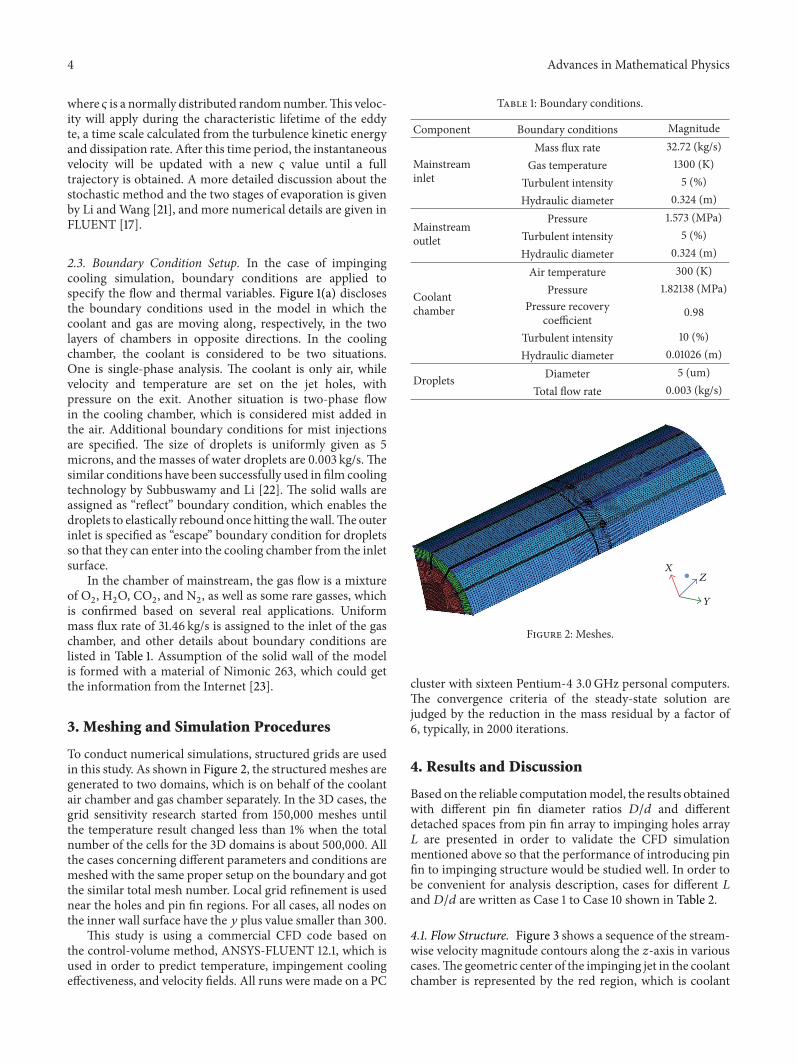
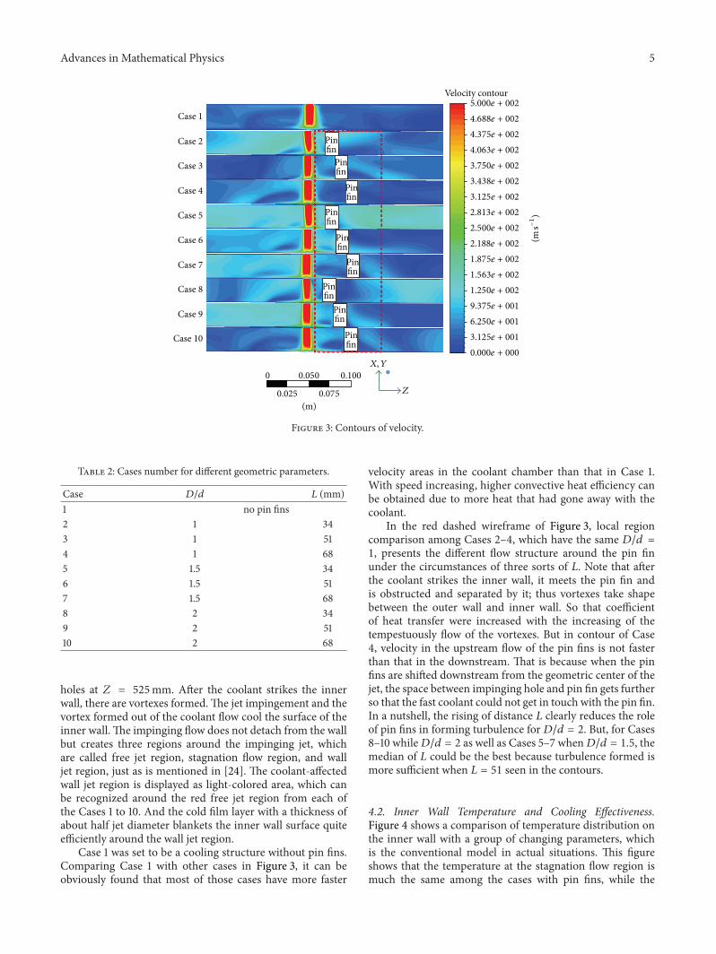
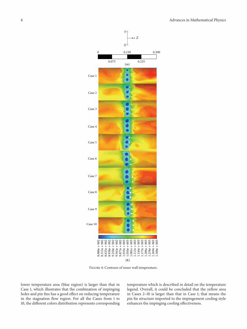
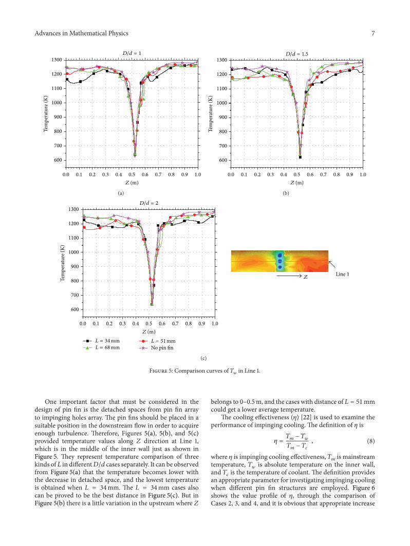
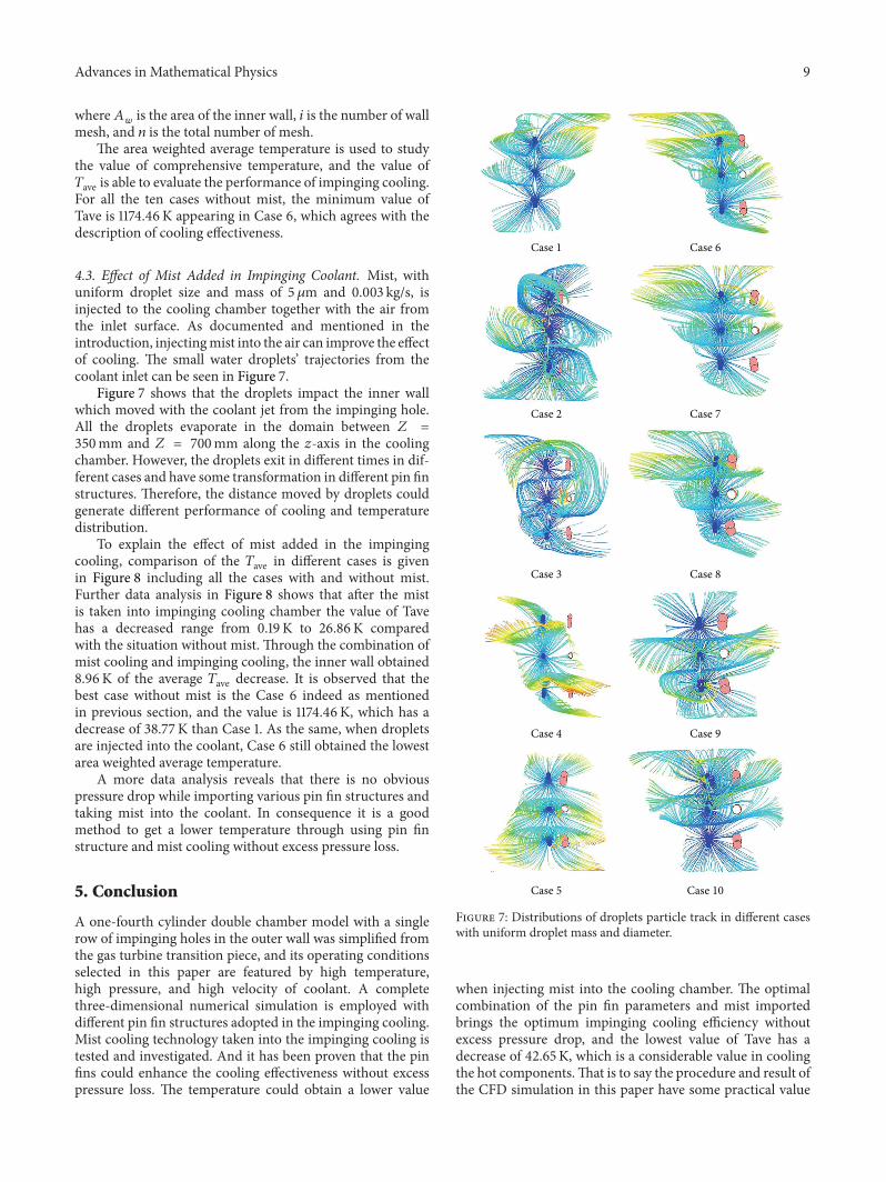
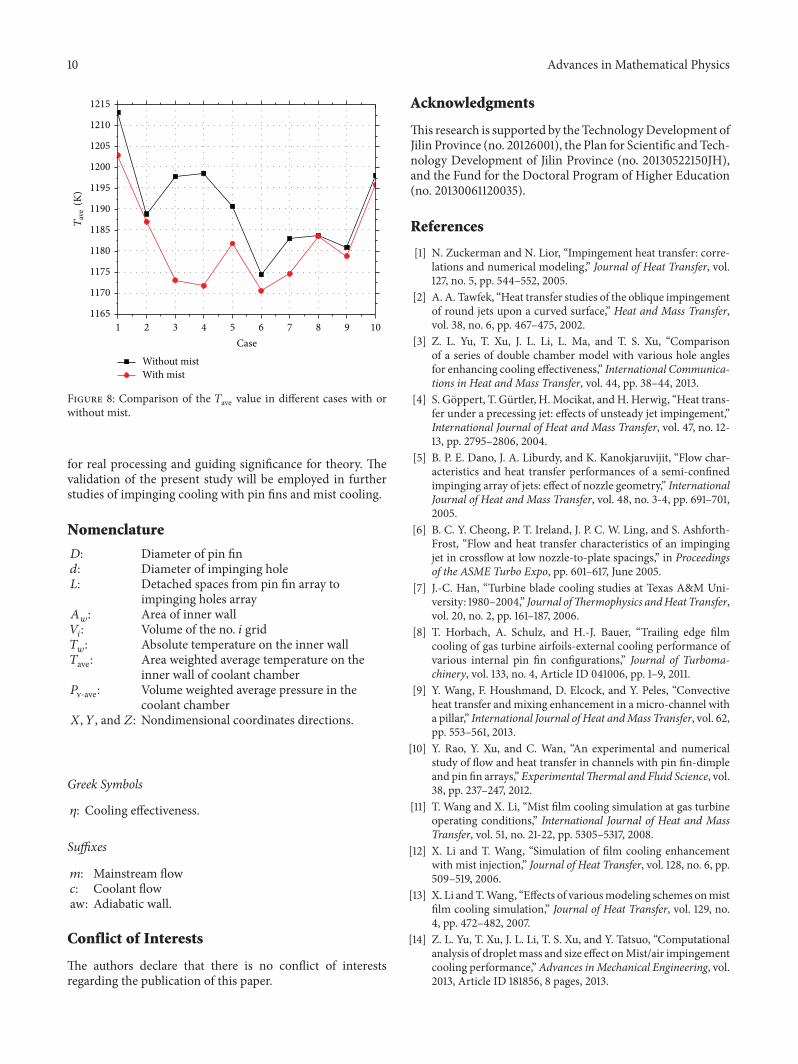