research article improving carrying capacity of … ii/ijaet vol ii issue ii... · research article...
TRANSCRIPT
International Journal of Advanced Engineering Technology E-ISSN 0976-3945
IJAET/Vol.II/ Issue II/April-June, 2011/231-238
Research Article
IMPROVING CARRYING CAPACITY OF RIVER TAPI (SURAT,
INDIA) BY CHANNEL MODIFICATION Agnihotri P.G
a and Patel J.N.
b
Address for Correspondence
a. Associate Professor b. Professor
Civil Engineering Department, S.V. National Institute of Technology, Ichchhanath, Surat – 395 007 (INDIA).
ABSTRACT
Surat city is situated at the bank of river Tapi (India) near its delta region. The flow of water and water level in the river Tapi is
controlled by Ukai dam which is 100 kms away from Surat city. The city has faced many floods since long. The aspects of
channel modification of river Tapi using geospatial technologies are proposed in this research paper. This is helpful in the
preparation of Flood Mitigation Plan for Surat city as a curative measure for the control of flood in the river Tapi. For channel
modification, software HEC-RAS is used. The flood inundation map of Surat city is prepared in Arc GIS using software HEC-
Geo RAS.
INTRODUCTION
River Tapi is originating from a Multai Hills
(Gavilgadh hill ranges of Satpura) and flowing
through three states Maharastra, Madya Pradesh and
Gujarat having length of 725 Kms. The flow of water
and water level in the river Tapi is controlled at Ukai
dam which is 100 kms away from Surat city. The
foundation of dam is resting on Dolerite dykes
(Basalt). It is constructed for irrigation purpose
mainly and also served the purpose of flood control,
generation of hydropower and supply of industrial
and drinking water. The average rainfall in the
catchment area is about 785 mm and average yearly
run off is 17,226 MCM. The area of Surat city
situated at delta stage of the river is 326.51 sq.km.
and population is about 40 lacs. The city is having
60,000 Shops & Establishment in trading activity.
The city is also famous for diamond industry. The
Major industries like Essar Steel, Reliance, ONGC, L
& T, Gail, Kribhco, Shell, NTPC, GSPC, Torrent
Power etc. are situated in the city. The study area is
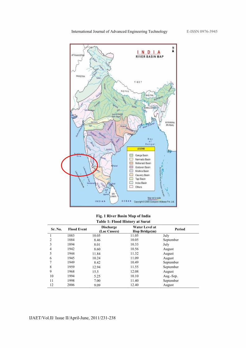
shown in Fig. No.1. Floods are occurring in river
Tapi time to time, due to which major portion of the
city is submerged creating lot of damage in
residential as well as industrial areas. There is a need
of reducing the effect of flood. In this paper the
aspects of river channel modification are considered
for enhancing the carrying capacity and reducing the
effect of flood in the city.
NECESSITY OF CHANNEL MODIFICATION
Flood occurs at Surat city frequently due to sudden
release of water from Ukai dam in river Tapi. At the
time of floods in river Tapi, Surat city and
surrounding regions are most affected. The city has
faced many floods since long back. There was a flood
in the Surat in 1959, 1968, 1998 and 2006. The
summary of the flood is given in the Table No. 1. The
Surat city and surrounding villages are part of flood
drainage of Tapi River. The carrying capacity of river
was about 6 Lacs cusecs. Since 1883 floods are
recorded in the month of August and September.
Major flood event took place in the year 1883, 1944,
1959, 1968, 1998 and 2006. The effective waterway
of river Tapi is reducing day by day with respect to
width and depth due to silting, which affect the
carrying capacity of the river. The dredging of river
in certain reaches can be carried out by conducting its
feasibility project. The computation for channel
modification of river Tapi has been carried out and
the enhanced cross section of river Tapi is suggested.
The channel modification is suggested in the reach of
river Tapi between Kathor to Magdalla. The
modification of river channel is done to increase the
carrying capacity of river Tapi and thus reducing the
effect of flood in Surat city and surrounding region.
CHANNEL MODIFICATION METHODS
Most widely used methods for channel modification
are discused below.
Levees
Levees are seldom equated with a channel
modification because, in most cases, they are
constructed well away from the channel. However, a
levee on one or both sides of a stream represents a
new and higher channel bankline for flood flows.
Levees confine the flood to a smaller cross section of
the floodplain and thus serve to channel flood flows
downstream. The benefits of levees are that they have
the least impact on the stream environment of any of
the structural flood reduction alternatives, and they
are nearly always the most effective and least
expensive method of reducing flooding to the
protected area.
International Journal of Advanced Engineering Technology E-ISSN 0976-3945
IJAET/Vol.II/ Issue II/April-June, 2011/231-238
Fig. 1 River Basin Map of India
Table 1: Flood History at Surat
Sr. No. Flood Event Discharge
(Lac Cusecs)
Water Level at
Hop Bridge(m) Period
1 1883 10.05 11.05 July
2 1884 8.46 10.05 September
3 1894 8.01 10.33 July
4 1942 8.60 10.56 August
5 1944 11.84 11.32 August
6 1945 10.24 11.09 August
7 1949 8.42 10.49 September
8 1959 12.94 11.55 September
9 1968 15.5 12.08 August
10 1994 5.25 10.10 Aug.-Sep.
11 1998 7.00 11.40 September
12 2006 9.09 12.40 August

International Journal of Advanced Engineering Technology E-ISSN 0976-3945
IJAET/Vol.II/ Issue II/April-June, 2011/231-238
High-Flow Diversion Channel and Weir
A high-flow diversion channel and weir refers to a
formal control structure that diverts some amount of
flow (can vary from a portion to most of the higher
flows) out of the river and into a separate channel,
usually moving the diverted flow along a different
flow path or to a different watershed. The diversion
of flow results in increased flood protection for land
and communities downstream of the flow split. The
diverted flow often rejoins the existing stream farther
downstream. The benefits of using this method are
that no modifications are made to the river channel,
and the diversion often takes place well upstream
from the protected area, improving visual aesthetics
(as opposed to when a levee or channel modification
is constructed to protect the area).
High-Flow Cutoff/Diversion Channel
A high-flow cutoff/diversion channel differs from a
high-flow diversion channel/weir in that a gated weir
structure is not needed at the diversion channel
entrance; the diversion channel is smaller, and the
diversion flow path is shorter-often just the distance
across the neck of a meander loop. During higher
flows, the diversion channel allows a portion of the
flow to follow a shorter, more efficient flow path.
The advantages are that the existing channel remains
unaffected and additional capacity is provided during
higher flows. As with the previous channel
modification types, the disadvantages are the land
costs required for the diversion channel, the loss of
this land for other purposes, and the need for erosion
control structures at the upstream and downstream
diversion boundary
Clearing and Snagging
Clearing and snagging involve removing vegetation
from the channel sides and along the bankline
(clearing) and removing trees, debris, and stumps
from the channel (snagging). The channel geometry
and alignment usually remain unchanged with this
solution, with the modification simply resulting in a
lower Manning's n value. Clearing and snagging is
therefore modeled in HEC-RAS by reducing the
channel n value. However, significant environmental
effects may result from this solution. Fish habitat and
cover are removed, the shade given by vegetation is
lost, and bottom sediments are resuspended by the
snagging.
Clearing and Enlarging One Side of the Channel
This technique combines clearing and snagging with
cutting, but only on one side of the existing channel.
Additional capacity is gained from the enlargement
and clearing of part of the channel. The same
environmental negatives and potential problems exist
for this solution as for the clearing and snagging and
compound channel options, but only for one side of
the channel. This solution is modeled in HEC-RAS
by adjusting both the geometry and the n value.
Widening the Upper Channel and Using the
Original Channel for Low Flow
Widening the upper channel and using the original
channel for low flow involves clearing and enlarging
both sides of the existing channel. The lowest
(deepest) portion of the existing channel is left as
undisturbed as possible to act as a low flow channel
during regular small events. Sedimentation in the cut
areas along with vegetative growth will make
maintaining the new capacity of the modification
difficult. This can be modeled in HEC-RAS similarly
to clearing and enlarging one side of the channel.
Realigning the Channel
When a channel is realigned, portions of the original
channel may be abandoned, as the modified portions
follow a new flow path for at least part of the reach.
If the total modified channel length is shorter than the
original channel length, a steeper invert slope will
occur. This will ultimately result in faster velocities,
and may significantly increase scour and deposition
problems along the realigned reach. One or more
erosion control structures are usually necessary for
this method. Realigned channels can be modeled in
HEC-RAS by locating the centerline station for the
new channel and adjusting the channel and overbank
reach lengths. The realignment may also include
increased cross-sectional area and a reduced n value.
HYDRAULIC DESIGN OF RIVER CHANNEL
The channel modification of River Tapi is done from
Kathor to Magdalla using concept of Most Efficient
sections. The channel is designed for carrying
different discharge of water using theory of practical
lined channel sections.
Design Procedure
The data given:
Discharge Q, Bed Slope of Channel S, Rugosity
Coefficient n, Maximum permissible velocity V and Side
slope of Channel m (m Horizontal to 1 Vertical)
To be evaluated:
Hydraulic Mean radius R, cross section area A,
wetted perimeter P, Bed width b and Depth of
water h
Equations used:
1. Continuity Equation Q = A*V

International Journal of Advanced Engineering Technology E-ISSN 0976-3945
IJAET/Vol.II/ Issue II/April-June, 2011/231-238
2. Maning’s Equation 2/13/21
SRn
V =
Design Steps
1. Area of cross section
( )θθ cot2 ++= hbhA
2. Perimeter of cross section
( )θθ cot2 ++= hbhP
3. Hydraulic mean radius of cross section
( )( )θθ
θθcot2
cot2
++++
=hbh
hbhR
Where, b = Bed width of Canal (m)
h = Depth of Water in Canal (m)
θ = Inclination of Side of Canal with
Horizontal at Top
4. P = A/R
From step 2 and 3
5. ( ) RAhbh /cot2 =++ θθ
( )θθ cot2/ +−= hRAb
From step 1 and 5
6. ( )( )θθ cot2/ ++−= hhRAA
( )θθ cot2 ++ h
7. ( ) ( )θθ cot/ 2 +−= hRAhA
( ) ( ) 0/cot2 =+−+ AhRAh θθ
02 =+− APhKh
Where K = θ + Cot(θ), P = A/R
8. In the above equation, value of A, R and P is
evaluated as follow:
A = Q/V
2/3
×=
s
vnR
P = A/R
9. The Equation shown in step-7 is Quadratic
Equation. Solving the equation and taking the
relevant root (the other root gives a negative
value); the value of h can be evaluated.
Sample Calculation
Data given
Discharge Q (Cumecs.) = 14158.42 (5,00,000
Cusecs)
Rugosity Coefficient n = 0.0225
Side Slope 1in m, m = 3
Bed Slope of Channel S = 0.00025
Velocity of Flow V (m/Sec.) = 2.35
1. Here ( ) 3cot =θ and θ = 0.321751 radian
2. K = θ + Cot(θ)
K = 0.321751 + 3 = 3.321751
3. Area of Cross section
A = 850/2.35 = 6024.86 m2
4. Hydraulic Mean Radius
2/3
000225.0
35.20225.
×=R = 6.11 m
5. Wetted Perimeter
P = A/R
P = 6155.83/5.92 = 985.20 m
6. Put the values of K,A and P in Quadratic
Equation shown in step-7,
3.321751h2 – 985.20h + 6024.86 = 0
Solving the quadratic equation,
h = 6.24 m (The other root h = 290.34 m
will give negative value of b)
7. The bed width of canal
3.321751* 6.24*26.11/ 6024.86 −=b
b = 943.70 m Say b = 944 m
In the Triangle ABC (Fig. 2)
Angle C = 90°, Angle A = θ and
Angle B = 90° - θ
8. b1 = h * Sin(θ)
b1 = 6.24 * Sin (0.321751) = 1.97 m
9. b2 = m * 6.24 * Cos (θ)
b2 = 3 * 5.413025 * Cos (0.321751)
= 17.78 m
10. y = h – h * Cos (θ)
y = 6.24 - 6.24 * Cos (0.321751)
= 0.32 m
11. The top width of canal T
T = b+2b1+2b2
T = 943.70 +(2 * 1.97) + (2 * 17.78)
T = 983.2 m
In case a larger or smaller depth is needed, some
adjustment can be made with the slope since the
given value is only the average slope of the terrain
and minor changes are always possible.
For Discharge 500000 Cusecs (14158.42 Cumecs)
Data Given
Rugosity Coefficient n = 0.0225
Side Slope 1in m = 3
Bed Slope of Channel S = 0.00025
Velocity of Flow V (m/Sec.) = 2.3
Calculated Quantities
Area of Cross Section A = 6024.86 m2
Hydraulic Mean Radius R = 6.11 m
Wetted Perimeter P = 985.2 m
Cot (θ) = 3
Value of θ in radian = 0.321751
International Journal of Advanced Engineering Technology E-ISSN 0976-3945
IJAET/Vol.II/ Issue II/April-June, 2011/231-238
Factor K = 3.321751
Depth of Water h1 = 290.34 m (Not considered)
Depth of Water h2 = 6.24 m
Bottom Width = 944 m
b1 = 1.97 m
b2 = 17.78 m
y = 0.32 m
Top Width = 983.2m
Design of River Channel for different discharge is
shown in Table No. 2.
MODIFICATION OF RIVER CHANNEL
The channel design/modification tools in HEC-RAS
allow the user to perform a series of trapezoidal cuts
into the existing channel geometry or to create new
channel geometry. The current version of HEC-RAS
has two tools for performing channel modifications.
These tools are available from the Tools menu of the
Geometric Data editor and are labeled Channel
Design/Modification and Channel Modification
(original). The tool labeled Channel
Design/Modification is a new tool for HEC-RAS
version 4.0. The tool labeled Channel Modification
(original) is the original channel modification tool
developed for HEC- RAS. The original channel
modification tool has been left in HEC-RAS for those
user’s who may prefer this tool to the new one. In
general, these tools are used for planning studies, but
it can also be used for hydraulic design of flood
control channels. In the present study, three different
modifications of river channel for three value of
discharge is discussed. The design parameters for
three different alternatives are mentioned in Table
No. 2. The modification of existing River section is
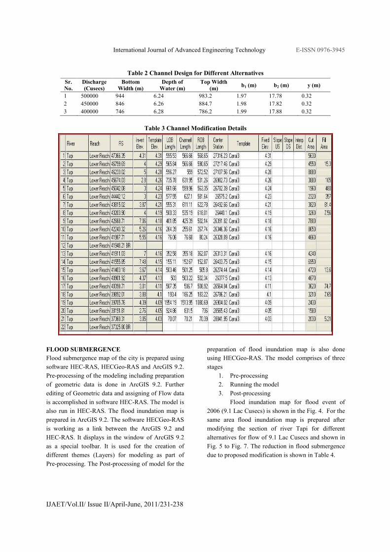
carried out using software HEC RAS 4.0. The sample
details of modification of river cross-section are
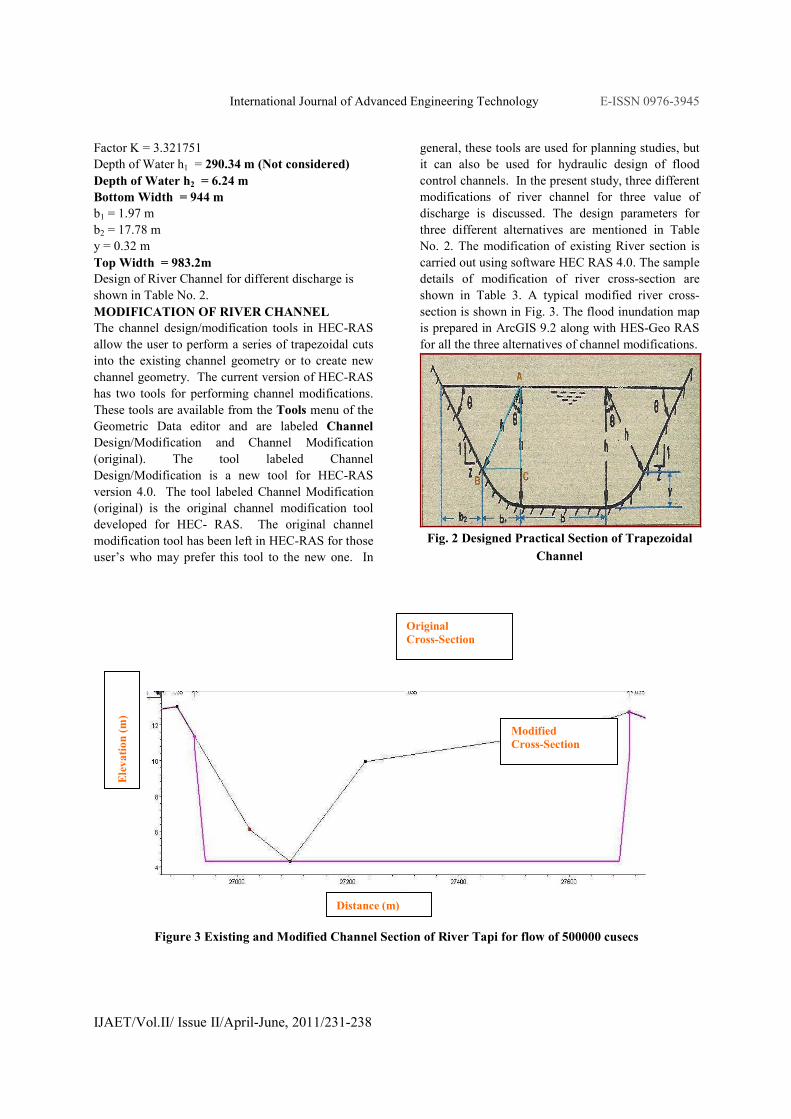
shown in Table 3. A typical modified river cross-
section is shown in Fig. 3. The flood inundation map
is prepared in ArcGIS 9.2 along with HES-Geo RAS
for all the three alternatives of channel modifications.
Fig. 2 Designed Practical Section of Trapezoidal
Channel
Figure 3 Existing and Modified Channel Section of River Tapi for flow of 500000 cusecs
Modified
Cross-Section
Original
Cross-Section
Distance (m)
Elevation (m)
International Journal of Advanced Engineering Technology E-ISSN 0976-3945
IJAET/Vol.II/ Issue II/April-June, 2011/231-238
Table 2 Channel Design for Different Alternatives
Sr.
No.
Discharge
(Cusecs)
Bottom
Width (m)
Depth of
Water (m)
Top Width
(m) b1 (m) b2 (m) y (m)
1 500000 944 6.24 983.2 1.97 17.78 0.32
2 450000 846 6.26 884.7 1.98 17.82 0.32
3 400000 746 6.28 786.2 1.99 17.88 0.32
Table 3 Channel Modification Details
FLOOD SUBMERGENCE
Flood submergence map of the city is prepared using
software HEC-RAS, HECGeo-RAS and ArcGIS 9.2.
Pre-processing of the modeling including preparation
of geometric data is done in ArcGIS 9.2. Further
editing of Geometric data and assigning of Flow data
is accomplished in software HEC-RAS. The model is
also run in HEC-RAS. The flood inundation map is
prepared in ArcGIS 9.2. The software HECGeo-RAS
is working as a link between the ArcGIS 9.2 and
HEC-RAS. It displays in the window of ArcGIS 9.2
as a special toolbar. It is used for the creation of
different themes (Layers) for modeling as part of
Pre-processing. The Post-processing of model for the
preparation of flood inundation map is also done
using HECGeo-RAS. The model comprises of three
stages
1. Pre-processing
2. Running the model
3. Post-processing
Flood inundation map for flood event of
2006 (9.1 Lac Cusecs) is shown in the Fig. 4. For the
same area flood inundation map is prepared after
modifying the section of river Tapi for different
alternatives for flow of 9.1 Lac Cusecs and shown in
Fig. 5 to Fig. 7. The reduction in flood submergence
due to proposed modification is shown in Table 4.

International Journal of Advanced Engineering Technology E-ISSN 0976-3945
IJAET/Vol.II/ Issue II/April-June, 2011/231-238
Table 4 Comparison of Inundated Area after Channel Modification for Flow of 9.1 Lac Cusecs
Modified
Carrying
Capacity
Total Area
of
Inundation
(% )
Area of
Inundation
< 2 m (% )
Area of
Inundation
2 - 5 m (% )
Area of
Inundation
5 - 8 m (% )
Area of
Inundation
8 - 11 m (% )
Area of
Inundation
> 11 m (% )
Existing 100 19.54 58.09 12.58 4.71 5.08
400000 Cusecs 87.51 35.27 36.12 7.64 4.65 3.82
450000 Cusecs 81.03 32.64 33.35 6.83 4.66 3.56
500000 Cusecs 78.30 31.77 32.34 6.22 4.61 3.35
Fig. No. 4 Flood Depth Map of Surat City for 9.1 Lac Cusecs Flow before modification of River Channel
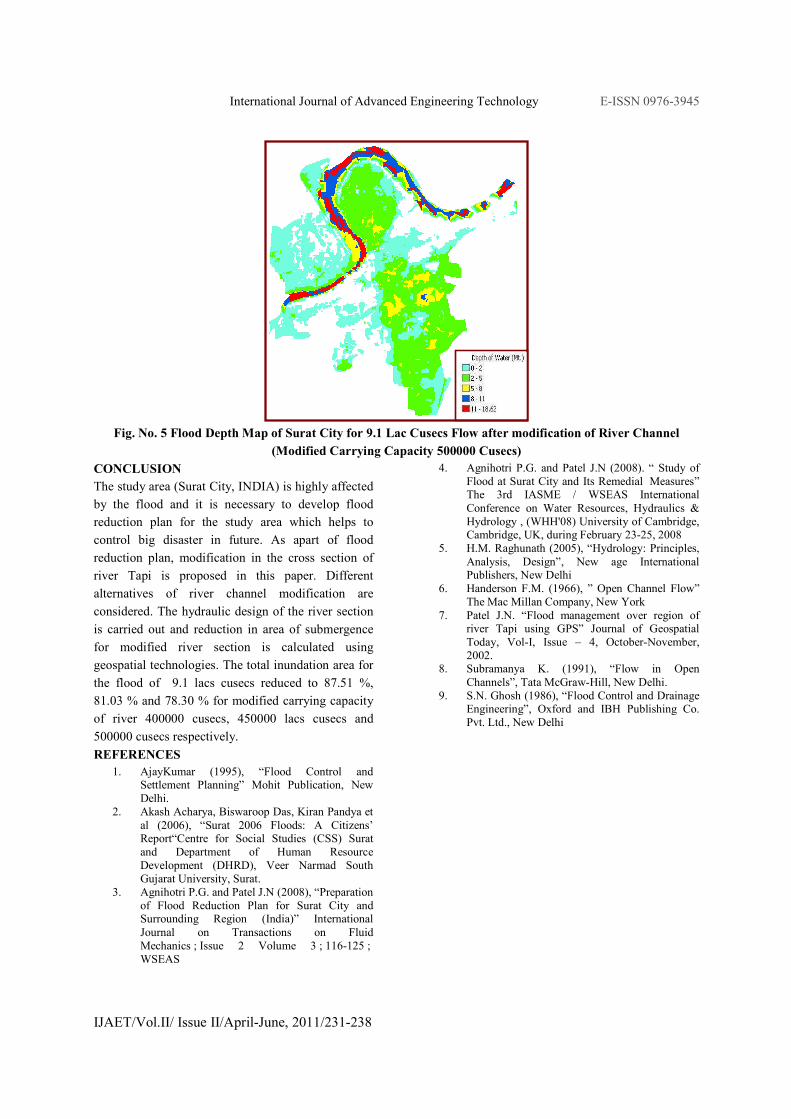
Fig. No. 5 Flood Depth Map of Surat City for 9.1 Lac Cusecs Flow after modification of River Channel
(Modified Carrying Capacity 400000 Cusecs)
Fig. No. 5 Flood Depth Map of Surat City for 9.1 Lac Cusecs Flow after modification of River Channel
(Modified Carrying Capacity 450000 Cusecs)
International Journal of Advanced Engineering Technology E-ISSN 0976-3945
IJAET/Vol.II/ Issue II/April-June, 2011/231-238
Fig. No. 5 Flood Depth Map of Surat City for 9.1 Lac Cusecs Flow after modification of River Channel
(Modified Carrying Capacity 500000 Cusecs)
CONCLUSION
The study area (Surat City, INDIA) is highly affected
by the flood and it is necessary to develop flood
reduction plan for the study area which helps to
control big disaster in future. As apart of flood
reduction plan, modification in the cross section of
river Tapi is proposed in this paper. Different
alternatives of river channel modification are
considered. The hydraulic design of the river section
is carried out and reduction in area of submergence
for modified river section is calculated using
geospatial technologies. The total inundation area for
the flood of 9.1 lacs cusecs reduced to 87.51 %,
81.03 % and 78.30 % for modified carrying capacity
of river 400000 cusecs, 450000 lacs cusecs and
500000 cusecs respectively.
REFERENCES
1. AjayKumar (1995), “Flood Control and
Settlement Planning” Mohit Publication, New
Delhi.
2. Akash Acharya, Biswaroop Das, Kiran Pandya et
al (2006), “Surat 2006 Floods: A Citizens’
Report“Centre for Social Studies (CSS) Surat
and Department of Human Resource
Development (DHRD), Veer Narmad South
Gujarat University, Surat.
3. Agnihotri P.G. and Patel J.N (2008), “Preparation
of Flood Reduction Plan for Surat City and
Surrounding Region (India)” International
Journal on Transactions on Fluid
Mechanics ; Issue 2 Volume 3 ; 116-125 ;
WSEAS
4. Agnihotri P.G. and Patel J.N (2008). “ Study of
Flood at Surat City and Its Remedial Measures”
The 3rd IASME / WSEAS International
Conference on Water Resources, Hydraulics &
Hydrology , (WHH'08) University of Cambridge,
Cambridge, UK, during February 23-25, 2008
5. H.M. Raghunath (2005), “Hydrology: Principles,
Analysis, Design”, New age International
Publishers, New Delhi
6. Handerson F.M. (1966), ” Open Channel Flow”
The Mac Millan Company, New York
7. Patel J.N. “Flood management over region of
river Tapi using GPS” Journal of Geospatial
Today, Vol-I, Issue – 4, October-November,
2002.
8. Subramanya K. (1991), “Flow in Open
Channels”, Tata McGraw-Hill, New Delhi.
9. S.N. Ghosh (1986), “Flood Control and Drainage
Engineering”, Oxford and IBH Publishing Co.
Pvt. Ltd., New Delhi