research article effect of stiffness of rolling joints on
TRANSCRIPT

Research ArticleEffect of Stiffness of Rolling Joints on the DynamicCharacteristic of Ball Screw Feed Systems in a Milling Machine
Dazhong Wang,1 Yan Lu,1 Tongchao Zhang,2 Keyong Wang,1 and Akira Rinoshika3
1Shanghai University of Engineering Science, Shanghai 201620, China2University of Shanghai for Science and Technology, Shanghai 200093, China3Yamagata University Faculty of Engineering, Yonezawa, Yamagata 992-8510, Japan
Correspondence should be addressed to Dazhong Wang; [email protected]
Received 10 January 2015; Revised 10 April 2015; Accepted 19 April 2015
Academic Editor: Jeong-Hoi Koo
Copyright © 2015 Dazhong Wang et al.This is an open access article distributed under the Creative Commons Attribution License,which permits unrestricted use, distribution, and reproduction in any medium, provided the original work is properly cited.
Dynamic characteristic of ball screw feed system in a milling machine is studied numerically in this work. In order to avoid thedifficulty in determining the stiffness of rolling joints theoretically, a dynamic modeling method for analyzing the feed system isdiscussed, and a stiffness calculation method of the rolling joints is proposed based on the Hertz contact theory. Taking a 3-axiscomputer numerical control (CNC) milling machine set ermined as a research object, the stiffness of its fixed joint between thecolumn and the body together with the stiffness parameters of the rolling joints is evaluated according to the Takashi Yoshimuramethod. Then, a finite element (FE) model is established for the machine tool. The correctness of the FE model and the stiffnesscalculation method of the rolling joints are validated by theoretical and experimental modal analysis results of the machine tool’sworkbench. Under the two modeling methods of joints incorporating the stiffness parameters and rigid connection, a theoreticalmodal analysis is conducted for the CNCmillingmachine.The natural frequencies andmodal shapes reveal that the joints’ dynamiccharacteristic has an important influence on the dynamic performance of a whole machine tool, especially for the case with naturalfrequency and higher modes.
1. Introduction
Ball screw feed drive system has become a key part of CNCmachine tools owning to its advantages of high positioningaccuracy and transmission efficiency, long operating life, andless internal heat [1, 2]; therefore its dynamic characteristichas a direct impact on positioning accuracy, processingperformance, vibration, and noise characteristic of amachinetool [3, 4]. The feed system is comprised of ball screwassembly, rolling guide pairs, bearings, workbench, body,and other parts through different kinds of mechanical joints;researches have shown that 30% to 50% static stiffness ofa machine tool depends on stiffness of joints, more than90% damping of a machine tool is derived from joints, andmore than 60% vibration problems that appear on a machinetool originate in joints [5], so dynamic characteristic of thejoints is one of the critical factors that influence the dynamic
performance of the feed system. Researches on identificationmethods of joints’ stiffness and damping parameters anddynamic characteristic analysis of the feed system are alwayshot issues in related field.
There are two types of joints in the feed system: fixedjoints as bolted joints and rolling joints including ball screwassembly, rolling guide paired, and bearing jointed. So far,the identification methods of joints’ dynamic characteristicparameters can be summarized into three kinds: theoreticalcalculation method, experimental test method, and theoret-ical calculation combined with experimental test method.As for the fixed joints, [6] proposed general theoreticalcalculation formulas of the fixed joints’ stiffness and dampingparameters through experimental data fitting, [7] obtainedstiffness and damping parameters of the fixed joint throughexperimental test, [8] identified the bolted joints’ dynamiccharacteristic parameters through theoretical calculation
Hindawi Publishing CorporationShock and VibrationVolume 2015, Article ID 697540, 11 pageshttp://dx.doi.org/10.1155/2015/697540

2 Shock and Vibration
combined with experimental test, and the above methods toidentify the fixed joints’ stiffness and damping parameterssatisfy the requirement of engineering practice appropriately.
As for the identification of rolling joints’ dynamic charac-teristic parameters, [9] took contact angle and contact defor-mation as variables and theoretically inferred themathemati-cal expression of ball screw assembly’s axial stiffness based oncoordinate change principle, [10] obtained parametric modeland nonparametricmodel of the rolling guide pair joint basedon theHertz contact theory and the two-dimensional Cheby-shev polynomial separately, [11] calculated dynamic supportstiffness of a high-speed motorized spindle bearing based onstatic and dynamic model of the angular contact bearing,and the theoretical calculation methods in above researchhave high precision and are suitable for intensive study of theball screw assembly, rolling guide pair, and bearing’s stiffness,but they are too complicated to be applied to stiffnessidentification of the joints in feed system; [12] measuredstiffness and damping parameters of a ball screw assembly bytest on a designed experimental platform, [13] developed ameasuring device based on the established equivalent singledegree of freedom system and identified the dynamic charac-teristic parameters of the Schneeberger MRC45 linear rollingguide, [14] obtained dynamic characteristic parameters ofan angel contact bearing through numerical simulation andexperimental test, and the experimental test methods inabove researches are accurate and reliable; otherwise, specialdesigned experiment platforms are needed which restrictstheir universality; therefore it is difficult to apply them tostiffness identification of the joints in feed system. Reference[15–17] identified the dynamic stiffness matrix of the bearing,stiffness and damping parameters of the rolling guide pair fora vertical machining center, and parameters of the ball screwassembly, rolling guide pair for a linear servo system throughthe combination of theoretical calculation and experimentaltest. The methods combining theoretical calculation andexperimental test in above researches need to obtain fre-quency response functions (FRFs) of the joints which aredifficult to measure sometimes due to restriction of practicalmechanical structures; therefore they are not applicable fordynamic characteristic parameters identification of the jointsin feed system. It is concluded that there is no method withgood accuracy, reliability, and convenience for the dynamiccharacteristic parameters identification of the joints in feedsystem.
In allusion to the above problem, with a 3-axis CNCmillingmachine taken as research object, this paper discussesthe dynamic modeling method of the feed system andproposes a stiffness calculation method of the rolling jointsbased on the Hertz contact theory. A finite element model ofthe CNC milling machine is established, and the correctnessof the FE model and the stiffness calculation method of therolling joints are verified by the comparison of theoretical andexperimental modal analysis of machine workbench. On thisbasis, under the two modelling methods of the joints takingstiffness into consideration and connecting joints rigidly,theoretical modal analysis of the CNC milling machine isimplemented, respectively, and the results are compared andanalyzed.
Motor Rolling guide
Nut base Screw nut
Workbench Bearing
Screw
Figure 1: Structure diagram of the feed system.
2. Dynamic Modeling of Feed System
Typical structure of a CNC machine tool feed system [18] isshown in Figure 1, an AC (Alternating Current) servo motordrives the ball screw to rotate by connection of the coupling,then the rotary motion is converted to linear motion throughthe screw nut, and finally the workbench implements itsstraight feed motion supported by four rolling guide pairs.The screw is supported by the left bearing pack and theright bearing pack, and the frequently used support modeof the screw in horizontal feed system is supported fixedat one end and simply supported at the other while it issupported fixed at both ends in vertical feed drive system.Theball screw assembly, rolling guide pairs, and bearings havebeen pretightened, and the screw has been prestretched andapplied with a preloading torque.
The fixed joints in the feed system mainly include boltedjoints between workbench and slide block, between work-bench and nut base, between body and bearing base, andbetween body andmotor base, while the rolling joints mainlyinclude the joints of ball screw assembly, rolling guide pair,and bearing. The most common method for modeling thejoints is to substitute several spring-damping units for theconnection between joints’ substructures.
In order to establish the dynamic model of feed systemmore conveniently, the fixed joints can be simplified as rigidconnection on account of their high stiffness. Although theAC servo motor, screw, bearings and other related parts arenot modeled in the analysis, their axial stiffness is carefullyincorporated. Based on the above simplified conditions,dynamic modeling method of the feed system [3] is as shownin Figure 2. Considering that damping parameters have tinyeffect on natural frequency, thus the user-definedMATRIX27stiffness element inANSYS software is utilized to simulate thecontact characteristic of joints. The workbench is connectedto the saddle with four parallelMATRIX27 stiffness elements,among which the stiffness of 𝑍 direction 𝐾
𝑧stands for
the normal stiffness of rolling guide pair, the stiffness of 𝑌direction 𝐾
𝑦denotes the tangential stiffness of rolling guide
pair, and the stiffness of 𝑋 direction 𝐾𝑥equals 25 percent
of axial feed unit’s equivalent stiffness constituted by the leftbearing pack, the ball screw assembly, and the right bearingpack.

Shock and Vibration 3
Ky
Ky
Kz
KzKz
KzKx
Kx Kx
Kx
Workbench
Saddle
Ky
Ky
Figure 2: Dynamic modeling of the feed system.
Q
Q
X
X
Y
Y
R11 R12
R22
R21
V2
V1
Figure 3: Hertz contact model.
3. Stiffness Calculation Method ofRolling Joints
3.1. Hertz Contact Theory. Hertz contact theory is the classi-cal theory to calculate contact deformation and contact stressof elastic body. As shown in Figure 3, two elastic objects 𝑉
1
and 𝑉2resist each other under the pressure of external force
𝑄, and the two objects satisfy the following assumptions [19]:materials of the two objects are homogeneous and isotropic;contact surface is so smooth that there is no tangentialfriction force existing at contact area; the contact objectsonly produce elastic deformation that obeys the Hooke law;size of the contact surface is very small compared with theobjects’ curvature radius. Therefore, in the center of contactarea, approaching distance resulting from the two objects thatresist each other is [3]
𝛿 =𝐾
𝜋𝑎(3𝑄
2(1 − 𝑢1
2
𝐸1
+1 − 𝑢2
2
𝐸2
))
2/3
(∑𝜌)1/3
, (1)
where 𝐾 and 𝑎 are Hertz coefficients, which can be obtainedby looking up tables in reference; 𝑢
1and 𝑢
2are Poisson ratio
of the two contact objects; 𝐸1and 𝐸
2are elastic modulus
of the two contact objects; ∑𝜌 is the synthetic curvature at
FU
FU
FL
FL
𝛽
𝛽
F
Figure 4: Force analysis of rolling guide joint.
contact point; namely,∑𝜌 = ∑2
𝑖=1∑2
𝑗=1(1/𝑅𝑖𝑗), where 𝑅
𝑖𝑗(𝑖 =
1, 2; 𝑗 = 1, 2) are principal curvatures of the object 𝑉𝑖.
As for the rolling joints of ball screw assembly, rollingguide pairs, and bearings in the feed system, the commonfeature is that they all contain the contact between ball andgroove; therefore the stiffness of rolling joints in feed systemcan be calculated based on the Hertz contact theory.
3.2. Stiffness of Rolling Guide Pair. Rolling guide pair iscomprised of slide block, balls, guides, and so on, assumingthat the contacts between ball and slide block groove, betweenball and guide groove satisfy the four conditions of the Hertzcontact theory; in addition, load is evenly distributed amongeach backing ball in the same row; then the normal andtangential stiffness of the rolling guide pair can be calculatedbased on the Hertz contact theory.
Typical structure of the rolling guide pair [3] is shownin Figure 4; there are four balls in joint, total number of thebacking balls is 𝑧, and pressure angle of the contact betweenball and groove is 𝛽. Under the pressure of external force 𝐹,normal reaction of each ball at up row is 𝐹
𝑈, and normal
reaction of each ball at low row is 𝐹𝐿. In general, each ball is
in compression owning to pretightened force, so the verticalforce equilibrium of the slide block is 𝐹 + 𝑧𝐹
𝐿sin𝛽/2 =
𝑧𝐹𝑈sin𝛽/2.Assuming that the pretightened force 𝐹
0is evenly dis-
tributed between all backing balls, normal force and initialdeformation of each ball induced by pretightened force are𝑃0and 𝛿
0, and the relationship between 𝑃
0and 𝐹
0is 𝐹0=
√2𝑧𝑃0sin𝛽. Under the pressure of external force 𝐹, the
deformation of each ball at up row is 𝛿𝑢, the deformation of
each ball at low row is 𝛿𝐿, and vertical displacement of slide
block is 𝛿𝑛; thus the compatibility equation of deformation
is (𝛿𝑢− 𝛿0) sin𝛽 = (𝛿
0− 𝛿𝐿) sin𝛽 = 𝛿
𝑛. Initial deformation
𝛿0can be obtained from (1), and 𝛿
𝑈= 𝑓𝑈(𝐹𝑈), 𝛿𝐿= 𝑓𝐿(𝐹𝐿).
Therefore, normal stiffness of the rolling guide pair can beobtained as𝐾
𝑛= 𝐹/𝛿
𝑛. Slide block is not subject to additional
tangential load, so tangential displacement of the slide blockrelative to the guide rail is 𝛿
𝜏= (𝛿𝑢− 𝛿0) cos𝛽. Therefore
tangential stiffness of the rolling guide pair can be calculatedas 𝐾𝜏= 𝑧𝑃0cos𝛽/2𝛿
𝜏[3].

4 Shock and Vibration
Workbench
Fixed endbearings
Simply endbearings
Screw Ball screwassembly
Figure 5: Dynamic model of ball screw feed unit.
l
L
Screw Screw nut
Figure 6: Schematic diagram of screw support mode.
3.3. Equivalent Stiffness of Axial Feed Unit. Dynamic modelof the axial feed unit is shown in Figure 5; equivalent axialstiffness 𝑘
𝑥is the synthesis of bearings axial stiffness, screw
axial stiffness, and ball screw assembly axial stiffness. Theaxial stiffness of the deep groove ball bearing used at thesimple end of screw is so small that can be neglected, so1/𝑘𝑥= 1/𝑘
𝑠+1/𝑘𝑎+1/𝑘𝑏[3], where 𝑘
𝑠is screw axial stiffness;
𝑘𝑎is ball screw assembly axial stiffness; 𝑘
𝑏is bearings axial
stiffness.
3.3.1. Screw Axial Stiffness. The screw is supported fixed atone end and simply supported at the other, which is shownin Figure 6. Screw axial stiffness can be calculated based onmechanics of materials as 𝑘
𝑠= 𝜋𝑑2
𝐸/4𝑙, where 𝑑 is minordiameter of the screw thread; 𝐸 is elasticity modulus of thescrew; 𝑙 is distance between the screw nut and the fixed end.The workbench and the saddle are usually located at the mid-point of travel range, without loss of generality, the stiffnessof the screw nut located at mid-point of screw is taken as itsaxial support stiffness; namely, 𝑘
𝑠= 𝜋𝑑2
𝐸/2𝐿.
3.3.2. Ball ScrewAssemblyAxial Stiffness. Ball screw assemblyis comprised of screw, balls, screw nut, and so on, assumingthat the contacts between ball and screw groove, betweenball and screw nut groove satisfy the four conditions ofthe Hertz contact theory; in addition (1) centrifugal forceand gyroscopic moment induced by balls rotation are sosmall that can be ignored; (2) axial load is evenly distributedbetween all backing balls; thus ball screw assembly axialstiffness can be calculated based on the Hertz contact theory.
Ball screw assembly of feed system is pretightened byapplying a preload, and external axial load can be neglected;force analysis of the ball screw assembly under the force ofpreload 𝐹
𝑎[3] is shown in Figure 7. Normal reaction of each
ball is𝑃, pressure angle of the contact between ball and grooveis 𝛽, deformation of the contact between ball and nut grooveis 𝛿1, and deformation of the contact between ball and screw
groove is 𝛿2. The axial force equilibrium of the screw nut is
Fa P
P
𝛿1
𝛿2
𝛽 · · ·· · ·
Figure 7: Force analysis of ball screw joint.
𝐹𝑎− 𝑃𝑧 sin𝛽 cos𝜙 = 0, where 𝑧 is total number of backing
balls; 𝜙 is lead angle of the screw. It is calculated from (1) that
𝛿𝑖=
𝐾𝑖
𝜋𝑎𝑖
(3𝑃
2(1 − 𝑢1
2
𝐸1
+1 − 𝑢2
2
𝐸2
))
2/3
(∑𝜌𝑖)1/3
,
𝑖 = 1, 2.
(2)
Synthetic curvature at contact point between each balland screwnut groove and synthetic curvature at contact pointbetween each ball and screw groove are [3]
∑𝜌1=
2
𝑑𝑏
+2
𝑑𝑏
−1
𝑑𝑏𝑓1
−2 cos𝛼 cos𝜙𝑑 + 𝑑𝑏cos𝛼
,
∑𝜌2=
2
𝑑𝑏
+2
𝑑𝑏
−1
𝑑𝑏𝑓2
+2 cos𝛼 cos𝜙𝑑 − 𝑑𝑏cos𝛼
,
(3)
where 𝑑𝑏is diameter of ball; 𝑓
1is a form factor, namely, the
ratio of screw nut groove’s curvature radius to ball radius; 𝑓2
is the ratio of screw groove’s curvature radius to ball radius.Axial displacement of screw nut to screw can be obtainedfrom geometrical relationship that 𝛿
𝑎= (𝛿1+𝛿2)/ sin𝛽 cos𝜙.
Ball screw assembly axial stiffness can be obtained by solvingsimultaneous (2)-(3) that𝐾
𝑎= 𝐹𝑎/𝛿𝑎.
3.3.3. Bearing Axial Stiffness. Bearing is comprised of innerring, balls, outer ring, and so on. Assuming that the contactsbetween ball and inner ring, between ball and outer ringsatisfy the four conditions of the Hertz contact theory;in addition (1) centrifugal force and gyroscopic momentinduced by ball rotation are so small that can be ignored; (2)axial load is evenly distributed between all backing balls; thusbearing axial stiffness can be calculated based on the Hertzcontact theory.
Taking the angular contact bearings used at fixed end asan example, the pretightened force 𝐹
𝑎is applied on bearings,
additional axial and radial forces induced by screw can beneglected, and force analysis of bearings [3] is shown inFigure 8. Pressure angle of the contact between ball andgroove is 𝛽, normal reaction of each ball is 𝑃, number ofballs in one bearing is 𝑧, deformation of the contact betweenball and outer groove is 𝛿
1, and deformation of the contact
between ball and inner groove is 𝛿2; thus the axial force

Shock and Vibration 5
Fa FaP
P P
P
𝛽 𝛽
Figure 8: Force analysis of bearing joint.
X
Y
Z
O
Body
Column
Saddle
Workbench
Spindle box
Servo motor
Figure 9: Structure diagram of CNC milling machine.
equilibriumof each bearing is𝐹𝑎−𝑧𝑃 sin𝛽 = 0. It is calculated
from (1) that
𝛿𝑖=
𝐾𝑖
𝜋𝑎𝑖
(3𝑃
2(1 − 𝑢1
2
𝐸1
+1 − 𝑢2
2
𝐸2
))
2/3
(∑𝜌𝑖)1/3
,
𝑖 = 1, 2,
(4)
where the meaning of each parameter in (4) is identical withthat in (2). Axial displacement of bearings to screw can beobtained from geometrical relationship that 𝛿
𝑎= (𝛿1+
𝛿2) sin𝛽. Bearing axial stiffness can be obtained by solving
simultaneous (4) as 𝑘𝑏= 𝐹𝑎/𝛿𝑎.
4. Finite Element Modeling
A CNC milling machine with three axes, 𝑋, 𝑌, and 𝑍,is determined as research object, its structure is shown inFigure 9, and three feed systems exist between column andspindle box, between body and saddle, and between saddleand workbench, respectively.
4.1. Stiffness Calculation of Fixed Joint. In order to establishFE model of the milling machine more easily, bolted jointbetween column and body is emphasized while the fixedjoints between guide and body, between slide block and
Table 1: Stiffness of bolted joints and parameters of stiffnesselements.
Direction Stiffness (N/m)Number ofstiffnesselements
Parameters ofstiffnesselements
Normal 5.07 × 10¹⁰ 16 3.12 × 10⁹
Tangential 2.02 × 10¹⁰ 16 1.26 × 10⁹
workbench, and between servo motor and spindle box areconnected rigidly with MPC184 element in ANSYS.
Takashi Yoshimura studied bolted joints inmachine tools.It was concluded that all these joints possess the samedynamic characteristic data per unit area if the averagecontact pressures at fixed joints are equal. As for the boltedjoint between column and body, the contact pressure can beconsidered as being uniformly distributed when neglectingthe influence of bolts distribution and structures physicaldeformation. Therefore, stiffness of the bolted joints canbe obtained through calculating contact pressure and theTakashi Yoshimura method. The column is connected to thebody with 16 parallel MATRIX27 stiffness elements; stiffnessof the bolted joints and parameters of the stiffness elementsare shown in Table 1.
4.2. Stiffness Calculation of Rolling Joints in Feed System.Stiffness of the rolling joints in 𝑋, 𝑌, and 𝑍 feed systemscan be obtained based on the proposed method in Section 3.Support mode of the screw in 𝑋 and 𝑌 feed systems issupported fixed at one end and simply supported at the other,among which a couple of angular contact bearings are usedat the fixed end and a deep groove ball bearing is used at thesimply supported end; support mode of the screw in 𝑍 feedsystem is supported fixed at both ends, amongwhich a center-oriented thrust ball bearing is used at each end.The calculatedstiffness of rolling joints in𝑋,𝑌, and𝑍 feed systems is shownin Tables 2, 3, and 4, respectively.
4.3. Finite Element Modeling of Milling Machine. Geometricmodel of the CNC milling machine is built and then istransmitted to HyperMesh to establish its finite elementmodel, during which some points should be focused on asfollows:
(1) Simplifying Geometric Model. In order to obtain morereasonable element shape generated by meshing andimprove the accuracy and efficiency of calculationand analysis, the geometric model is simplified beforebuilding finite element model as follows: little boltholes and other process holes are neglected; filletingand chamfering are straight lined; motors and othercomponents that have little effect on calculation resultare ignored; equivalentmass blocks are substituted forcomplicated parts inside of the spindle box.
(2) Finite Element Meshing. Element type of the wholemodel is chosen as Solid92, which is a tetrahedralelement with 10 nodes; about 29.4 million Solid92elements are obtained by meshing.

6 Shock and Vibration
X Y
Z
O
0
0.0129
34
0.025868
0.038803
0.051737
0.064671
0.077605
0.090539
0.103473
0.116408
(a) The 1st vibration mode
0
0.0123
22
0.024644
0.036967
0.049289
0.061611
0.073933
0.086255
0.098577
0.1109
X Y
Z
O
(b) The 2nd vibration mode
0
0.017746
0.035492
0.053238
0.070984
0.0887
3
0.106476
0.124223
0.141969
0.159715
X Y
Z
O
(c) The 3rd vibration mode
0
0.0184
0.036801
0.055201
0.073602
0.092002
0.1104
03
0.128803
0.147204
0.165604
X Y
Z
O
(d) The 4th vibration mode
Figure 10: Theoretical vibration modes of workbench.
Table 2: Stiffness of rolling joints in𝑋 feed system.
Normal stiffness ofrolling guide 𝐾
𝑧
(N/um)
Tangential stiffness ofrolling guide 𝐾
𝑦
(N/um)
Axial stiffness ofscrew 𝑘
𝑠(N/um)
Stiffness of ball screw𝑘𝑎(N/um)
Axial stiffness ofbearings 𝑘
𝑏(N/um)
Axial equivalentstiffness 𝐾
𝑥(N/um)
156 112 443 290 503 130
Table 3: Stiffness of rolling joints in 𝑌 feed system.
Normal stiffness ofrolling guide 𝐾
𝑧
(N/um)
Tangential stiffness ofrolling guide 𝐾
𝑦
(N/um)
Axial stiffness ofscrew 𝑘
𝑠(N/um)
Stiffness of ball screw𝑘𝑎(N/um)
Axial stiffness ofbearings 𝑘
𝑏(N/um)
Axial equivalentstiffness 𝐾
𝑥(N/um)
182 131 591 290 503 141
Table 4: Stiffness of rolling joints in 𝑍 feed system.
Normal stiffness ofrolling guide 𝐾
𝑧
(N/um)
Tangential stiffness ofrolling guide 𝐾
𝑦
(N/um)
Axial stiffness ofscrew 𝑘
𝑠(N/um)
Stiffness of ball screw𝑘𝑎(N/um)
Axial stiffness ofbearing 𝑘
𝑏(N/um)
Axial equivalentstiffness 𝐾
𝑥(N/um)
167 120 752 165 373 225
Shock and Vibration 7
Acceleration sensors
Force hammer
NI dataacquisition equipment
Modal View modalanalysis software
Workbench
Figure 11: Working principle of modal testing system.
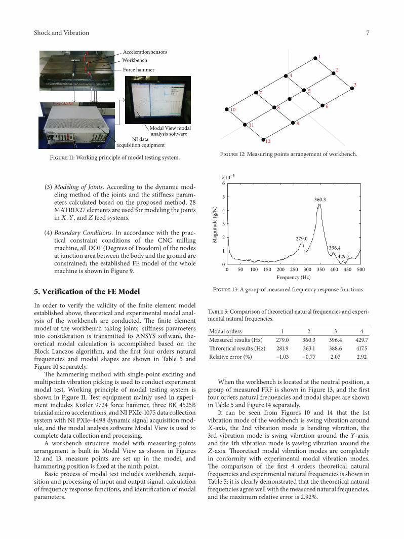
(3) Modeling of Joints. According to the dynamic mod-eling method of the joints and the stiffness param-eters calculated based on the proposed method, 28MATRIX27 elements are used for modeling the jointsin𝑋, 𝑌, and 𝑍 feed systems.
(4) Boundary Conditions. In accordance with the prac-tical constraint conditions of the CNC millingmachine, all DOF (Degrees of Freedom) of the nodesat junction area between the body and the ground areconstrained; the established FE model of the wholemachine is shown in Figure 9.
5. Verification of the FE Model
In order to verify the validity of the finite element modelestablished above, theoretical and experimental modal anal-ysis of the workbench are conducted. The finite elementmodel of the workbench taking joints’ stiffness parametersinto consideration is transmitted to ANSYS software, the-oretical modal calculation is accomplished based on theBlock Lanczos algorithm, and the first four orders naturalfrequencies and modal shapes are shown in Table 5 andFigure 10 separately.
The hammering method with single-point exciting andmultipoints vibration picking is used to conduct experimentmodal test. Working principle of modal testing system isshown in Figure 11. Test equipment mainly used in experi-ment includes Kistler 9724 force hammer, three BK 4525Btriaxial micro accelerations, andNI PXIe-1075 data collectionsystem with NI PXIe-4498 dynamic signal acquisition mod-ule, and the modal analysis software Modal View is used tocomplete data collection and processing.
A workbench structure model with measuring pointsarrangement is built in Modal View as shown in Figures12 and 13, measure points are set up in the model, andhammering position is fixed at the ninth point.
Basic process of modal test includes workbench, acqui-sition and processing of input and output signal, calculationof frequency response functions, and identification of modalparameters.
1
2
3
4
5
6
7
8
9
10
11
12
Figure 12: Measuring points arrangement of workbench.
×10−3
50 100
Mag
nitu
de (g
/N)
396.4
429.7
400 450 500150
360.3
350
279.0
200 250 300
Frequency (Hz)
00
1
2
3
4
5
6
Figure 13: A group of measured frequency response functions.
Table 5: Comparison of theoretical natural frequencies and experi-mental natural frequencies.
Modal orders 1 2 3 4Measured results (Hz) 279.0 360.3 396.4 429.7Throretical results (Hz) 281.9 363.1 388.6 417.5Relative error (%) −1.03 −0.77 2.07 2.92
When the workbench is located at the neutral position, agroup of measured FRF is shown in Figure 13, and the firstfour orders natural frequencies and modal shapes are shownin Table 5 and Figure 14 separately.
It can be seen from Figures 10 and 14 that the 1stvibration mode of the workbench is swing vibration around𝑋-axis, the 2nd vibration mode is bending vibration, the3rd vibration mode is swing vibration around the 𝑌-axis,and the 4th vibration mode is yawing vibration around the𝑍-axis. Theoretical modal vibration modes are completelyin conformity with experimental modal vibration modes.The comparison of the first 4 orders theoretical naturalfrequencies and experimental natural frequencies is shown inTable 5; it is clearly demonstrated that the theoretical naturalfrequencies agree well with themeasured natural frequencies,and the maximum relative error is 2.92%.

8 Shock and Vibration
2.2E − 1
1.6E − 1
1.1E − 1
5.4E − 2
0.0E + 0
Z
YX
(a) The 1st vibration mode
5.5E − 1
3.7E − 1
1.8E − 1
0.0E + 0
Z
YX
(b) The 2nd vibration mode
1.7E − 1
1.3E − 1
8.5E − 2
4.3E − 2
0.0E + 0
Z
YX
(c) The 3rd vibration mode
4.3E − 1
3.2E − 1
2.1E − 1
1.1E − 1
0.0E + 0
Z
YX
(d) The 4th vibration mode
Figure 14: Experimental vibration modes of workbench.
The correctness of the finite element model is verified bythe comparison of theoretical natural frequencies and modalshapes and their corresponding experimental results, whichalso indicates that the stiffness calculation method proposedin this paper is right and feasible.
6. Dynamic Characteristic Analysis of CNCMilling Machine
The finite element model of the CNC milling machine istransmitted to ANSYS for modal calculation; the first fourorders natural frequencies and modal shapes of the wholemachine tool are shown in Table 6 and Figure 15 separately.
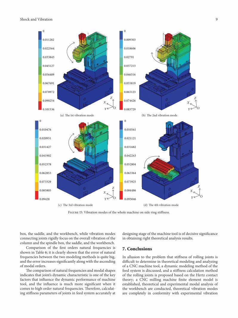
It can be seen fromFigure 15 that the 1st vibrationmode ofthemachine tool is low order pitching vibration of the spindleand the column, the 2nd vibrationmode is swing vibration ofthe spindle and the column around𝑋-axis, the 3rd vibrationmode is high order pitching vibration of the spindle and thecolumn, and the 4th vibration mode is swing vibration of theworkbench and the saddle around𝑋-axis.
Furthermore, regardless of joints’ stiffness parametersand connecting joints rigidly in finite element model withMPC184 element, theoretical modal calculation is conducted
Table 6: Comparison of natural frequencies under the two model-ing methods of joints.
Modal orders 1 2 3 4Flexible connection (Hz) 44.4 49.4 85.5 98.2Rigid connection (Hz) 66.8 69.8 160.0 178.8Absolute error (Hz) 22.4 20.1 74.5 80.6
on the model with rigid connection; the first four ordersnatural frequencies and modal shapes are shown in Table 6and Figure 16 separately.
It can be seen fromFigure 16 that the 1st vibrationmode ofthemachine tool is low order pitching vibration of the spindleand the column, the 2nd vibrationmode is swing vibration ofthe spindle and the column around𝑋-axis, the 3rd vibrationmode is high order pitching vibration of the spindle, and the4th vibration mode is swing vibration of the spindle around𝑍-axis.
The first four orders vibration modes of the wholemachine tool have great difference under the two model-ing methods of joints. Vibration modes considering jointsstiffness mainly present as local vibration of the spindle
Shock and Vibration 9
0
0.011282
0.022564
0.033845
0.045127
0.056409
0.067691
0.078972
0.090254
0.101536 OY
X
Z
(a) The 1st vibration mode
0
0.009303
0.018606
0.02791
0.037213
0.046516
0.055819
0.065123
0.074426
0.083729 OY
X
Z
(b) The 2nd vibration mode
0
0.010476
0.020951
0.031427
0.041902
0.052378
0.062853
0.073329
0.083805
0.09428 OY
X
Z
(c) The 3rd vibration mode
0
0.010561
0.021121
0.031682
0.042243
0.052804
0.063364
0.073925
0.084486
0.095046OY
X
Z
(d) The 4th vibration mode
Figure 15: Vibration modes of the whole machine on side ring stiffness.
box, the saddle, and the workbench, while vibration modesconnecting joints rigidly focus on the overall vibration of thecolumn and the spindle box, the saddle, and the workbench.
Comparison of the first orders natural frequencies isshown in Table 6; it is clearly shown that the error of naturalfrequencies between the two modeling methods is quite big,and the error increases significantly along with the ascendingof modal orders.
The comparison of natural frequencies and modal shapesindicates that joint’s dynamic characteristic is one of the keyfactors that influence the dynamic performance of machinetool, and the influence is much more significant when itcomes to high order natural frequencies. Therefore, calculat-ing stiffness parameters of joints in feed system accurately at
designing stage of the machine tool is of decisive significancein obtaining right theoretical analysis results.
7. Conclusions
In allusion to the problem that stiffness of rolling joints isdifficult to determine in theoretical modeling and analyzingof a CNC machine tool, a dynamic modeling method of thefeed system is discussed, and a stiffness calculation methodof the rolling joints is proposed based on the Hertz contacttheory; a CNC milling machine finite element model isestablished, theoretical and experimental modal analysis ofthe workbench are conducted, theoretical vibration modesare completely in conformity with experimental vibration

10 Shock and Vibration
0
0.009286
0.018573
0.027859
0.037145
0.046432
0.055718
0.065004
0.074291
0.083577
OY
XZ
(a) The 1st vibration mode
0
0.008852
0.017705
0.026557
0.035409
0.044262
0.053114
0.061967
0.070819
0.079671
O
Y
X
Z
(b) The 2nd vibration mode
0
0.015321
0.030641
0.045962
0.061282
0.076603
0.091923
0.107244
0.122564
0.137885
OY
XZ
(c) The 3rd vibration mode
0
0.012476
0.024952
0.037428
0.049904
0.06238
0.074856
0.087332
0.099808
0.112284O
Y
XZ
(d) The 4th vibration mode
Figure 16: Vibration modes of the whole machine with rigid connection.
modes, and the error between theoretical natural frequencyand experimental natural frequency is within 2.92%, whichvertify the correctness of the finite element model and thestiffness calculation method of the rolling joints; under thetwo modelling methods of joints taking stiffness into con-sideration and connecting joints rigidly, theoretical modalanalysis of the CNC milling machine is implemented, thecomparison of natural frequencies and modal shapes indi-cates that joints’ dynamic characteristic parameter is one ofthe key factors that influence the dynamics performance ofa machine tool, and the influence is much more significantwhen it comes to natural frequencies and modal shapes ofhigh orders; the proposed stiffness calculation method ofthe rolling joints has the advantages of accurate, reliable,
and good practicability, which laid a foundation for dynamicmodeling of the feed system more accurately.
Conflict of Interests
The authors declare that there is no conflict of interestsregarding the publication of this paper.
Acknowledgments
The project is sponsored by the Scientific Research Foun-dation for the Returned Overseas Chinese Scholars, StateEducation Ministry (2013 no. 8), and 2014 Shanghai “Over-seas Outstanding Professor.” The authors would like to thank

Shock and Vibration 11
the editor and the reviewers for their constructive commentsand suggestions which improved the quality of this paper.
References
[1] D. A. Vicente, R. L. Hecker, F. J. Villegas, and G. M. Flores,“Modeling and vibration mode analysis of a ball screw drive,”The International Journal of Advanced Manufacturing Technol-ogy, vol. 58, no. 1–4, pp. 257–265, 2012.
[2] Y. Altintas, A. Verl, C. Brecher, L. Uriarte, and G. Pritschow,“Machine tool feed drives,” CIRP Annals—Manufacturing Tech-nology, vol. 60, no. 2, pp. 779–796, 2011.
[3] J. M. Zhu, T. C. Zhang, and X. R. Li, “Dynamic charac-teristics analysis of ball screw feed system based on stiff-ness characteristic of mechanical joints,” Journal of MechanicalEngineering, http://www.cnki.net/kcms/detail/11.2187.TH.20141211.0839.025.html.
[4] Y. Altintas, C. Brecher, M. Week, and S. Witt, “Virtual machinetool,” CIRP Annals—Manufacturing Technology, vol. 54, no. 2,pp. 651–674, 2005.
[5] G. P. Zhang, Y. M. Huang, W. H. Shi, and W. P. Fu, “Predictingdynamic behaviours of a wholemachine tool structure based oncomputer-aided engineering,” International Journal of MachineTools & Manufacture, vol. 43, no. 7, pp. 699–706, 2003.
[6] S. Choi, S. Park, C.-H. Hyun, M.-S. Kim, and K.-R. Choi,“Modal parameter identification of a containment using ambi-ent vibration measurements,” Nuclear Engineering and Design,vol. 240, no. 3, pp. 453–460, 2010.
[7] K. Mao, B. Li, J. Wu, and X. Shao, “Stiffness influential factors-based dynamic modeling and its parameter identificationmethod of fixed joints inmachine tools,” International Journal ofMachine Tools & Manufacture, vol. 50, no. 2, pp. 156–164, 2010.
[8] H. Ahmadian and H. Jalali, “Identification of bolted lap jointsparameters in assembled structures,” Mechanical Systems andSignal Processing, vol. 21, no. 2, pp. 1041–1050, 2007.
[9] C. C. Wei and J. F. Lin, “Kinematic analysis of the ball screwmechanism considering variable contact angles and elasticdeformations,” Transactions of the ASME, Journal of MechanicalDesign, vol. 125, no. 4, pp. 717–733, 2004.
[10] J. S. Dhupia, A. G. Ulsoy, R. Katz, and B. Powalka, “Experimen-tal identification of the nonlinear parameters of an industrialtranslational guide for machine performance evaluation,” Jour-nal of Vibration and Control, vol. 14, no. 5, pp. 645–668, 2008.
[11] J. Jedrzejewski and W. Kwasny, “Modelling of angular contactball bearings and axial displacements for high-speed spindles,”CIRPAnnals—Manufacturing Technology, vol. 59, no. 1, pp. 377–382, 2010.
[12] X. Cheng, J. F. Shi, and S. Zhang, “A study on dynamiccharacteristics of the joint surfaces of ball screw assembly,”China Mechanical Engineering, vol. 5, no. 1, pp. 29–31, 1994.
[13] H. Zhang, J. Yuan, and Z. Wang, “Experimental research onidentification of dynamic characteristic parameters of rollingguide’s joint,” China Mechanical Engineering, vol. 22, no. 4, pp.415–418, 2011.
[14] R. Tiwari and V. Chakravarthy, “Simultaneous estimation of theresidual unbalance and bearing dynamic parameters from theexperimental data in a rotor-bearing system,” Mechanism andMachine Theory, vol. 44, no. 4, pp. 792–812, 2009.
[15] P. Cermelj and M. Boltezar, “An indirect approach to investi-gating the dynamics of a structure containing ball bearings,”Journal of Sound and Vibration, vol. 276, no. 1-2, pp. 401–417,2004.
[16] P. Kolar, M. Sulitka, and M. Janota, “Simulation of dynamicproperties of a spindle and tool system coupled with a machinetool frame,”The International Journal of Advanced Manufactur-ing Technology, vol. 54, no. 1–4, pp. 11–20, 2011.
[17] T. Yang and C.-S. Lin, “Identifying the stiffness and dampingparameters of a linear servomechanism,” Mechanics BasedDesign of Structures and Machines, vol. 32, no. 3, pp. 283–304,2004.
[18] B. Li, B. Luo, X. Mao, H. Cai, F. Peng, and H. Liu, “A newapproach to identifying the dynamic behavior of CNCmachinetools with respect to different worktable feed speeds,” Interna-tional Journal of Machine Tools & Manufacture, vol. 72, pp. 73–84, 2013.
[19] E. David and J. Bernard, “Simplified solution for point contactdeformation between two elastic solids,” Nasa Technical Mem-orandum, 1976.

International Journal of
AerospaceEngineeringHindawi Publishing Corporationhttp://www.hindawi.com Volume 2014
RoboticsJournal of
Hindawi Publishing Corporationhttp://www.hindawi.com Volume 2014
Hindawi Publishing Corporationhttp://www.hindawi.com Volume 2014
Active and Passive Electronic Components
Control Scienceand Engineering
Journal of
Hindawi Publishing Corporationhttp://www.hindawi.com Volume 2014
International Journal of
RotatingMachinery
Hindawi Publishing Corporationhttp://www.hindawi.com Volume 2014
Hindawi Publishing Corporation http://www.hindawi.com
Journal ofEngineeringVolume 2014
Submit your manuscripts athttp://www.hindawi.com
VLSI Design
Hindawi Publishing Corporationhttp://www.hindawi.com Volume 2014
Hindawi Publishing Corporationhttp://www.hindawi.com Volume 2014
Shock and Vibration
Hindawi Publishing Corporationhttp://www.hindawi.com Volume 2014
Civil EngineeringAdvances in
Acoustics and VibrationAdvances in
Hindawi Publishing Corporationhttp://www.hindawi.com Volume 2014
Hindawi Publishing Corporationhttp://www.hindawi.com Volume 2014
Electrical and Computer Engineering
Journal of
Advances inOptoElectronics
Hindawi Publishing Corporation http://www.hindawi.com
Volume 2014
The Scientific World JournalHindawi Publishing Corporation http://www.hindawi.com Volume 2014
SensorsJournal of
Hindawi Publishing Corporationhttp://www.hindawi.com Volume 2014
Modelling & Simulation in EngineeringHindawi Publishing Corporation http://www.hindawi.com Volume 2014
Hindawi Publishing Corporationhttp://www.hindawi.com Volume 2014
Chemical EngineeringInternational Journal of Antennas and
Propagation
International Journal of
Hindawi Publishing Corporationhttp://www.hindawi.com Volume 2014
Hindawi Publishing Corporationhttp://www.hindawi.com Volume 2014
Navigation and Observation
International Journal of
Hindawi Publishing Corporationhttp://www.hindawi.com Volume 2014
DistributedSensor Networks
International Journal of