research article a very compact and sharp roll-off low...
TRANSCRIPT

Research ArticleA Very Compact and Sharp Roll-Off Low-Pass Filterwith Four Transmission Zeros
Yang Xiao and Lin Li
Department of Electronic Engineering, Zhejiang Sci-Tech University, Hangzhou, Zhejiang 310018, China
Correspondence should be addressed to Lin Li; lilin [email protected]
Received 30 April 2015; Accepted 30 July 2015
Academic Editor: Flavio Canavero
Copyright © 2015 Y. Xiao and L. Li. This is an open access article distributed under the Creative Commons Attribution License,which permits unrestricted use, distribution, and reproduction in any medium, provided the original work is properly cited.
A novel structure with sharp roll-off, wide stopband, and very compact size is presented in this paper. By combining a capacitor-embedded transmission line ring and two shunt open stubs, this structure exhibits a high-performance three-pole low-pass filter(LPF) response with four generated transmission zeros. With the help of these four transmission zeros, the proposed LPF achievesimproved roll-off rate, extended stopband, and significantly very compact size. To verify the feasibility of the proposed structure,a prototype LPF having the cut-off frequency at 0.63GHz is designed, fabricated, and measured as an illustrative example. Finalresult shows that a roll-off rate of 109.3 dB/GHz along with a relative stopband bandwidth of 114.6% can be obtained. Moreover, thefilter dimensions are as small as 15.7mm × 26.9mm, that is, 0.004𝜆
𝑔
2, where 𝜆𝑔is the guided wavelength at the cut-off frequency.
The filter structure is simple and easy to fabricate as well.
1. Introduction
High-performance low-pass filters (LPFs) with the compactsize are highly desirable to remove the unwanted high-frequency harmonics and intermodulations in various wire-less communication systems. Conventional transmission lineLPFs, such as open-circuited stub and stepped-impedanceLPFs, often suffer from gradual cut-off attenuation skirt,narrow stopband bandwidth, and large circuit size [1]. Forachieving the requirement of high performance, the usualapproach is to raise the order of stepped-impedance LPFs to agreat extent. Unfortunately, both the circuit size and in-bandinsertion loss increase considerably.
Recently, many studies in defected ground structure(DGS) have been made to obtain LPF with sharp roll-off rate, wide stopband characteristic, and compact size [2,3]. However, the design procedure of DGS has fabricationdifficulties and DGS itself will cause radiation. Except forDGS, another method to realize compact LPF is to introducetransmission zeros in the filter’s transfer function. Generatingtransmission zero points and properly locating them candevelop sharp response from passband to stopband anddeep rejection outside the passband. Thus, a low-order LPFwith the help of extra transmission zero points can meet
the stop band requirements that are usually achieved byhigh-order filters. In [4], the stepped-impedance hairpinresonator is adapted to design wideband LPF. However,the roll-off skirt of this LPF is very gradual as only onetransmission zero is excited in the stopband, which is veryfar away from the cutoff frequency. And, in [5, 6], twotransmission zeros are produced to improve the stopbandbehavior by introducing the CSRR (complementary split ringresonators) and interdigital DGS, respectively. Nevertheless,the stopband characteristics remain to be enhanced dueto finite transmission zeros. Therefore, in order to excitemultiple transmission zeros to broaden the stopband andsharpen the roll-off skirt, multisection structures have beenengineered in [7–9], for instance, in [7], a cascaded unitcomposed of two asymmetrical hairpin units as well as aconnecting line is employed to obtain a very wide stopbandLPFwith five proposed transmission zeros; additionally in [8,9], the cascades of variousTFSs (transversal filtering sections)and several CPW (coplanar-waveguide) tapered sectionsare exploited to obtain an extraordinary sharp-rejection,ultralarge attenuated band LPF with multiple transmissionzeros. Despite so many attractive features, these multisectionLPFs [7–9] generally have large circuit size, which greatlyhinder their further developments and applications. Owing
Hindawi Publishing CorporationActive and Passive Electronic ComponentsVolume 2015, Article ID 806276, 6 pageshttp://dx.doi.org/10.1155/2015/806276
2 Active and Passive Electronic Components
to the gradual roll-off skirt, complex fabrication, and largecircuit size, these structures fail to meet the increasing higherdemand of high-performance LPFs with the compact size.
In this paper, a novel structure composed of a capacitor-embedded ring as well as two symmetrical open stubsconnected at the two bilateral tapped points is proposed tosolve the problem above. Detailed analysis based on matricestransformation reveals that the proposed structure exhibitsthree-pole low-pass filtering response with four adjustabletransmission zeros. By properly adjusting and locating thefour transmission zeros, not only sharp and wide rejectionbut also size reduction can be addressed simultaneously. Thedesign, simulation, and measurement of the exemplary filtersuccessfully verify the feasibility of the proposed structure torealize high-performance LPF with very compact size.
2. Theoretical Analysis
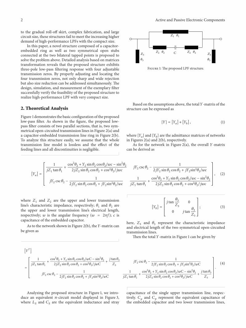
Figure 1 demonstrates the basic configuration of the proposedlow-pass filter. As shown in the figure, the proposed low-pass filter consists of two parallel sections, that is, two sym-metrical open-circuited transmission lines in Figure 2(a) anda capacitor-embedded transmission line ring in Figure 2(b).To analyze this structure easily, we assume that the wholetransmission line model is lossless and the effect of thefeeding lines and all discontinuities is negligible.
Z3
𝜃3
Z3
𝜃3
Z2 𝜃2Z2 𝜃2
Z1 𝜃1
C
Figure 1: The proposed LPF structure.
Based on the assumptions above, the total𝑌-matrix of thestructure can be expressed as
[𝑌] = [𝑌𝑎] + [𝑌𝑏] , (1)
where [𝑌𝑎] and [𝑌𝑏] are the admittance matrices of networksin Figures 2(a) and 2(b), respectively.
As for the network in Figure 2(a), the overall 𝑌-matrixcan be derived as
[𝑌𝑎] =
[[[[[
[
1𝑗𝑍1 tan 𝜃1
+
cos2𝜃2 + 𝑌2 sin 𝜃2 cos 𝜃2/𝑤𝑐 − sin2𝜃2
2𝑗𝑍2 sin 𝜃2 cos 𝜃2 + cos2𝜃2/𝑗𝑤𝑐𝑗𝑌2 csc 𝜃2 −
12𝑗𝑌2 sin 𝜃2 cos 𝜃2 + 𝑗𝑌2sin2𝜃2/𝑤𝑐
𝑗𝑌2 csc 𝜃2 −1
2𝑗𝑌2 sin 𝜃2 cos 𝜃2 + 𝑗𝑌2sin2𝜃2/𝑤𝑐1
𝑗𝑍1 tan 𝜃1+
cos2𝜃2 + 𝑌2 sin 𝜃2 cos 𝜃2/𝑤𝑐 − sin2𝜃2
2𝑗𝑍2 sin 𝜃2 cos 𝜃2 + cos2𝜃2/𝑗𝑤𝑐
]]]]]
]
, (2)
where 𝑍1 and 𝑍2 are the upper and lower transmissionline’s characteristic impedance, respectively; 𝜃1 and 𝜃2 arethe upper and lower transmission line’s electrical length,respectively; 𝑤 is the angular frequency (𝑤 = 2𝜋𝑓); 𝑐 iscapacitance of the embedded capacitor.
As to the network shown in Figure 2(b), the𝑌-matrix canbe given as
[𝑌𝑏] =
[[[
[
𝑗 tan𝜃3𝑍3
0
0 𝑗 tan𝜃3𝑍3
]]]
]
; (3)
here, 𝑍3 and 𝜃3 represent the characteristic impedanceand electrical length of the two symmetrical open-circuitedtransmission lines.
Then the total 𝑌-matrix in Figure 1 can be given by
[𝑌𝑇]
=
[[[[[
[
1𝑗𝑍1 tan 𝜃1
+
cos2𝜃2 + 𝑌2 sin 𝜃2 cos 𝜃2/𝑤𝐶 − sin2𝜃2
2𝑗𝑍2 sin 𝜃2 cos 𝜃2 + cos2𝜃2/𝑗𝑤𝐶+
𝑗 tan 𝜃3𝑍3
𝑗𝑌2 csc 𝜃2 −1
2𝑗𝑌2 sin 𝜃2 cos 𝜃2 + 𝑗𝑌2sin2𝜃2/𝑤𝐶
𝑗𝑌2 csc 𝜃2 −1
2𝑗𝑌2 sin 𝜃2 cos 𝜃2 + 𝑗𝑌2sin2𝜃2/𝑤𝐶1
𝑗𝑍1 tan 𝜃1+
cos2𝜃2 + 𝑌2 sin 𝜃2 cos 𝜃2/𝑤𝐶 − sin2𝜃2
2𝑗𝑍2 sin 𝜃2 cos 𝜃2 + cos2𝜃2/𝑗𝑤𝐶+
𝑗 tan 𝜃3𝑍3
]]]]]
]
.
(4)
Analyzing the proposed structure in Figure 1, we intro-duce an equivalent 𝜋-circuit model displayed in Figure 3,where 𝐿𝑆 and 𝐶𝑆 are the equivalent inductance and stray
capacitance of the single upper transmission line, respec-tively. 𝐶𝑔 and 𝐶𝑝 represent the equivalent capacitance ofthe embedded capacitor and two lower transmission lines,

Active and Passive Electronic Components 3
C
Z1 𝜃1
Z2 𝜃2 Z2 𝜃2
(a)
Z3
𝜃3
Z3
𝜃3
(b)
Figure 2: (a) Capacitor-embedded transmission line ring. (b) Two symmetrical open-circuited transmission lines.
Cstub CstubCp CpCs CsCg
Ls
Figure 3: Equivalent 𝜋-circuit model of the proposed structure.
respectively. Finally, 𝐶stub is found as the equivalent capaci-tance of the two open-circuited transmission lines jointed attwo ends.Thus the overall structure can be equivalent as a 𝜋-circuit model. Furthermore, the parameters of the proposedequivalent 𝜋-circuit can be described as
𝐿 𝑠 =
𝑍1 sin 𝜃1𝑤
(𝐻) , (5a)
𝐶𝑠 =
1 − cos 𝜃1𝑤𝑍1 sin 𝜃1
(𝐹) , (5b)
𝐶𝑔 =
𝐶
cos2𝜃2 − 2𝑤𝐶 sin 𝜃2 cos 𝜃2/𝑌2(𝐹) , (5c)
𝐶𝑝 =
2𝑐sin2𝜃2 + sin 𝜃2 cos 𝜃2𝑌2/𝑤cos2𝜃2 − 2𝑤𝑐 sin 𝜃2 cos 𝜃2/𝑌2
(𝐹) , (5d)
𝐶stub =𝑍3 tan 𝜃3𝑤
(𝐹) . (5f)
Obviously, the proposed structure behaves quasiellipticlow-pass filtering characteristics. By using the classic methodat the cut-off frequency, the prototype element values inFigure 3 can be synthesized and then the physical dimen-sions of the proposed structure can also be obtained. Toconfirm the validity of the presented equivalent model andcorresponding synthesis method, a low-pass filter using theproposed structure is designed to provide a 0.1 dB equal-ripple Chebyshev response. The optimized parameters of theproposed structure are 𝑍1 = 105Ω, 𝑍2 = 90Ω, and 𝑍3 =48.5Ω; 𝜃1 = 120
∘, 𝜃2 = 8∘ at 2GHz, and 𝜃3 = 90
∘ at 1 GHz;𝐶 = 0.75 pF. Both the ideal response and the response of thesynthesized circuit are shown in Figure 4. And to compare theproposed structure and the conventional LPF, the response
0 1 2 3 4 5
L-C LPFProposed LPFStep-impedance LPF
0
−20
−40
−60
−80
S 21
(dB)
Frequency (GHz)
Figure 4: Simulated responses of the L-C LPF, proposed LPF, andthe step-impedance LPF.
of the conventional stepped-impedance LPF is also displayedin Figure 4. Good agreement can be observed, indicatingthe feasibility of the proposed structure and the synthesismethod.
As evidently illustrated in Figure 4, multiple transmissionzeros appear on the response of the proposed structure.With the help of the four transmission zeros, the proposedstructure exhibits much higher selectivity and much widerstopband than the conventional stepped-impedance LPF.
The transmission zeros of the proposed structure arelocated at the frequency where 𝑆21 = 0. From the relationship

4 Active and Passive Electronic Components
between the admittance matrices and scatteringmatrices, thescattering matrices of the total network can be given by
𝑆21 =−2𝑌21𝑌0
(𝑌11 + 𝑌0) (𝑌22 + 𝑌0) − 𝑌12𝑌21, (6)
where𝑌0 is the characteristic admittance of the input port andthe output port.
Then by setting 𝑌21 = 0 or 𝑌11 = ∞, 𝑆21 = 0 can beobtained and the frequency of the finite transmission zerosshould satisfy either of the following equations:
csc 𝜃1𝑍1= 2𝜋𝑓𝐶𝑔, (7)
tan 𝜃3 = ∞. (8)
Apparently, the transmission zeros come from the coun-teraction of the two signal paths in Figure 2(a) and the seriesresonance of the bilateral two open stubs in Figure 2(b).Besides, the two transmission zero generation mechanismsare mutually independent, which provide great flexibility forfilter analysis and design.
Firstly, the structure in Figure 2(a) has a similar topologyto the filter in [10]. In fact, the structure in Figure 2(a) willbe deformed to the filter in [10] when 𝜃2 = 0. As illustratedin [10], a larger parallel capacitor creates larger transmissionzero separations. And it can be deduced from (5c) that theintroduction of the bilateral transmission line (𝑍 = 90Ω,𝜃 = 8
∘ at 2GHz) will largely magnify the capacitance of𝐶. As a result, the proposed structure can generate twotransmission zeros withmuchwider zero separation and thusensure a wider rejection band. Besides, the introduction ofa larger parallel capacitor can not only lower the filter’s cut-off frequency but also enhance the selectivity considerably.Furthermore, a larger parallel capacitor indicates a moreremarkable size reduction of the upper line’s electrical length,meaning that the whole circuit can be further minimized.
As for the structure in Figure 2(b), based on the twogenerated transmission zeros derived from (7), another twotransmission zeros 𝑓𝑧3 and 𝑓𝑧4 can be obtained when 𝜃3 =𝜋/2 and 𝜃3 = 3𝜋/2, which makes 𝑓𝑧4 = 3𝑓𝑧3 = 3GHz; hencethe overall frequency response with four transmission zerosis realized. Besides, the locations of 𝑓𝑧3 and 𝑓𝑧4 can be shiftedflexibly and easily by altering the electrical length of the twosymmetrical open-circuited lines depending on the designedgoal. Evidently, when the locations of 𝑓𝑧1 and 𝑓𝑧2 have beenpredetermined, the locations of 𝑓𝑧3 and 𝑓𝑧4 have a significantinfluence on the filter’s overall frequency responses. Differenttransmission zero’s locations will lead to different frequencyresponses.Then select an appropriate 𝜃3 and let the 𝑓𝑧3 locatebefore 𝑓𝑧1 while the 𝑓𝑧4 locate behind the 𝑓𝑧2; to do so, theroll-off rate will be significantly upgraded as the result of theeffect of 𝑓𝑧3; meanwhile, the stopband bandwidth will extendto the upper side and create wider stopband owing to theimpact of 𝑓𝑧4. Therefore, as obviously depicted in Figure 5,the proposed low-pass filter with two symmetrical open-circuited lines ensures a wider stopband, sharper roll-offrate, and deeper rejection level. Apart from these interestingcharacteristics, the open-circuited lines hardly brings about
0
−20
−40
−60
−80
S 21
(dB)
0 1 2 3 4 5
Frequency (GHz)
With stubsWithout stubs
Figure 5: The simulated frequency response with and without thestubs.
influence to passband frequency response meaning that it isconvenient for further design and adjustment. Furthermore,the introduced open-circuited transmission lines can befolded easily so as to contribute to the miniaturization ofthe whole circuit, thereby achieving a balance between theexcellent performance and the compact size.
3. Fabrication and Measurements
Based on the above-discussed attractive features, a prototypeLPF having 𝑓𝑐 of 0.63GHz and a wide 20 dB stopbandextended up to 5𝑓𝑐 is implemented on a substrate withthickness of 0.5mm and relative dielectric constant of 2.65and loss tangent of 0.02. The physical dimensions alongwith the photograph of the proposed LPF are demonstratedin Figures 6(a) and 6(b). The parameters of the proposedstructure are arranged as follows: 𝑤1 = 0.33mm, 𝑙1 =14.15mm, 𝑤2 = 0.47mm, 𝑙2 = 2.32mm, 𝑤3 = 1.3mm,𝑙3 = 11.92mm, 𝑙4 = 13.3mm, 𝑤50 = 1.34mm, 𝑙50 =25.18mm, and 𝐶 = 0.75 pF which are achieved by using theMURATA patch capacitors with the size of 1.6mm × 0.8mm.Meandered lines are adapted to achieve a very compact area.The Ansoft software High Frequency Structure Simulator(HFSS) is used for the microstrip line simulations while theAgilent 8510C vector network analyzer is applied for thecorresponding measurements.
Figure 7 shows an excellent agreement between the mea-sured and simulated frequency responses; the measured 3 dBcut-off frequency is 0.63GHz and the passband insertionloss including the SMA connector loss is within 0.5 dB upto 0.54GHz, while the return loss is better than 12 dB up to0.31 GHz. The measured four transmission zeros are locatedat 1.1 GHz (with a suppression of 59.15 dB), 1.76GHz (witha suppression of 41.45 dB), 2.75GHz (with a suppressionof 79.42 dB), and 3.1 GHz (with a suppression of 45.6 dB),respectively. With the aid of these transmission zeros, the

Active and Passive Electronic Components 5
Table 1: Comparison with the reported LPFs.
References RO (dB/GHz) fc (GHz)Stopband
Ckt. size (𝜆𝑔
2)Up to (fc) Demon. FBW (%) Rej. (dB)[3] 34 2.4 3.4 95,20 0.049[4] 68 2.0 5 120,33.5 Large[5] 130 1.8 3.4 Unknown 0.02[7] 37 2.5 4.8 115,20 0.022[8] 270 1.0 5.3 135,21.5 Large[11] 95 0.5 9 140,20 0.022This work 109.3 0.63 5 114,20 0.004RO: roll-off; Demon.: demonstrated; FBW: fractional bandwidth; Rej.: rejection level; Ckt.: circuit.
l0
l1
w1
w50C l2w2
w3
l50
l4
l3
(a) (b)
Figure 6: (a) The layout and physical dimensions of the proposed LPF. (b) The photograph of the proposed LPF.
SimulationMeasurement
0
−20
−40
−60
−80
S21S11
S-pa
ram
eter
s (dB
)
0 1 2 3 4 5
Frequency (GHz)
Figure 7: Simulated and measured frequency responses of thefabricated LPF.
measured 20 dB rejection stopband extends from 0.85GHzto 3.13 GHz, forming a very wide attenuation band with the20 dB rejection bandwidth up to 5.04𝑓𝑐.Moreover, these deeprejection transmission zeros also create a sharp transition forthe filter; thus the proposed LPF exhibits an incredible roll-off rate of 109.3 dB/GHz (measured attenuations being 3 dB
and 50 dB at 0.63GHz and 1.06GHz, resp.). In addition, thecentral circuit (without the consideration of the 50Ω feedline) occupies a really compact size of 26.9mm × 15.7mm,corresponding to 0.004𝜆𝑔
2 (0.083𝜆𝑔 × 0.049𝜆𝑔), where 𝜆𝑔 isthe guided wavelength of a 50Ω transmission line at the cut-off frequency 0.63GHz.
A comparison of the proposed LPF with other reportedcompact sharp roll-off LPFs is provided in Table 1. Comparedwith the LPFs in the table, the proposed low-pass filterbehaves a wide stopband and rather steep roll-off rate.Furthermore, the size of the proposed LPF is the smallestamong the LPFs in Table 1, indicating that it is a goodcandidate to satisfy the requirement of miniaturization.
4. Conclusions
Thedesign of a compact sharp roll-off low-pass filter based onthe novel structure is presented in this paper. It is analyzedin theory that the proposed structure can produce fouradjustable transmission zeros by changing the parameters ofthe circuit to obtain the wanted LPF. Applying the analysismethod, a prototype LPF is designed, fabricated, and tested.Measured results agree well with the theoretical predictionsand demonstrate its incredible features: sharp roll-off rate,wide stopband, and very compact size. With all these charm-ing characteristics, the proposed LPF is very applicable in themodern communication system.

6 Active and Passive Electronic Components
Conflict of Interests
The authors declare that there is no conflict of interestsregarding the publication of this paper.
Acknowledgments
Thisworkwas supported by the program for Zhejiang leadingteam of science and technology innovation (2011R50004),the National Natural Science Foundation of China underGrant 61101052 and 521 talent project of Zhejiang Sci-TechUniversity.
References
[1] J.-S. G. Hong and M. J. Lancaster, Microstrip Filter forRF/Microwave Applications, Wiley, New York, NY, USA, 2001.
[2] R. Sharma, T. Chakravarty, S. Bhooshan, and A. B. Bhat-tacharyya, “Design of a novel 3 DB microstrip backwardwave coupler using defected ground structure,” Progress inElectromagnetics Research, vol. 65, pp. 261–273, 2006.
[3] Y. Jinping and W. Wen, “Compact elliptic-function low-passfilter using defected ground structure,” IEEE Microwave andWireless Components Letters, vol. 18, no. 9, pp. 578–580, 2008.
[4] L.-H. Hsieh andK. Chang, “Compact elliptic-function low-passfilters using microstrip stepped-impedance hairpin resonators,”IEEE Transactions onMicrowaveTheory and Techniques, vol. 51,no. 1, pp. 193–199, 2003.
[5] M. K. Mandal, P. Mondal, S. Sanyal, and A. Chakrabarty, “Lowinsertion-loss, sharp-rejection and compact microstrip low-pass filters,” IEEE Microwave and Wireless Components Letters,vol. 16, no. 11, pp. 600–602, 2006.
[6] A. Balalem, A. R. Ali, J. Machac, and A. Omar, “Quasi-ellipticmicrostrip low-pass filters using an interdigital DGS slot,” IEEEMicrowave and Wireless Components Letters, vol. 17, no. 8, pp.586–588, 2007.
[7] S. Luo, L. Zhu, and S. Sun, “Stopband-expanded low-pass filtersusing microstrip coupled-line hairpin units,” IEEE Microwaveand Wireless Components Letters, vol. 18, no. 8, pp. 506–508,2008.
[8] R. Gomez-Garcıa, M.-A. Sanchez-Soriano, M. Sanchez-Renedo, G. Torregrosa-Penalva, and E. Bronchalo, “Low-passand bandpass filters with ultra-broad stopband bandwidthbased on directional couplers,” IEEE Transactions onMicrowaveTheory and Techniques, vol. 61, no. 12, pp. 4365–4375, 2013.
[9] D. Kaddour, E. Pistono, J. Duchamp et al., “A compact andselective low-pass filter with reduced spurious responses, basedon CPW tapered periodic structures,” IEEE Transactions onMicrowaveTheory and Techniques, vol. 54, no. 6, pp. 2367–2375,2006.
[10] J.-W. Sheen, “A compact semi-lumped low-pass filter for har-monics and spurious suppression,” IEEE Microwave and Wire-less Components Letters, vol. 10, no. 3, pp. 92–93, 2000.
[11] V. K.Velidi and S. Sanyal, “Sharp roll-off lowpass filter withwidestopband using stub-loaded coupled-line hairpin unit,” IEEEMicrowave and Wireless Components Letters, vol. 21, no. 6, pp.301–303, 2011.

International Journal of
AerospaceEngineeringHindawi Publishing Corporationhttp://www.hindawi.com Volume 2014
RoboticsJournal of
Hindawi Publishing Corporationhttp://www.hindawi.com Volume 2014
Hindawi Publishing Corporationhttp://www.hindawi.com Volume 2014
Active and Passive Electronic Components
Control Scienceand Engineering
Journal of
Hindawi Publishing Corporationhttp://www.hindawi.com Volume 2014
International Journal of
RotatingMachinery
Hindawi Publishing Corporationhttp://www.hindawi.com Volume 2014
Hindawi Publishing Corporation http://www.hindawi.com
Journal ofEngineeringVolume 2014
Submit your manuscripts athttp://www.hindawi.com
VLSI Design
Hindawi Publishing Corporationhttp://www.hindawi.com Volume 2014
Hindawi Publishing Corporationhttp://www.hindawi.com Volume 2014
Shock and Vibration
Hindawi Publishing Corporationhttp://www.hindawi.com Volume 2014
Civil EngineeringAdvances in
Acoustics and VibrationAdvances in
Hindawi Publishing Corporationhttp://www.hindawi.com Volume 2014
Hindawi Publishing Corporationhttp://www.hindawi.com Volume 2014
Electrical and Computer Engineering
Journal of
Advances inOptoElectronics
Hindawi Publishing Corporation http://www.hindawi.com
Volume 2014
The Scientific World JournalHindawi Publishing Corporation http://www.hindawi.com Volume 2014
SensorsJournal of
Hindawi Publishing Corporationhttp://www.hindawi.com Volume 2014
Modelling & Simulation in EngineeringHindawi Publishing Corporation http://www.hindawi.com Volume 2014
Hindawi Publishing Corporationhttp://www.hindawi.com Volume 2014
Chemical EngineeringInternational Journal of Antennas and
Propagation
International Journal of
Hindawi Publishing Corporationhttp://www.hindawi.com Volume 2014
Hindawi Publishing Corporationhttp://www.hindawi.com Volume 2014
Navigation and Observation
International Journal of
Hindawi Publishing Corporationhttp://www.hindawi.com Volume 2014
DistributedSensor Networks
International Journal of