requirements report for ssto vertical take … · ssd94d0217b requirements report for ssto vertical...
TRANSCRIPT
SSD94D0217B
Requirements Report for SSTOVertical Take-Off/Horizontal
Landing Vehicle
Cooperative AgreementsNCC1-193, NCC2-9003, and NCC8-39
November 4, 1994
H. S. Greenberg, Principal Investigator
0 6_ Rockwell _
SpaceSystomsDivision
N4C_J"_I4_ QRI_INAN
6_ Rockwell A,_ce
North American Aircraft
https://ntrs.nasa.gov/search.jsp?R=19950008380 2018-09-01T14:48:01+00:00Z

i:_:i:i:i3i:iS!:i:i:i:i:iqi:i:¸:,:,.,. ,..::,::,_::,
i:i:iv,:i,i ::i _ ,:iq:::
::< .,: , i::,i i i.::• ,, ..... •::::_::::::v:::_d::::_,.. . ,..,
iiiiiiii!iiiii iiiiiiii <,::::: :,;;,
:.x,,x:::,;:i:iS::}i:i_::
....
iiiiiiil
i:i:i:i:i:i3i!iiii!
iii ii!!iii!ii
iiii!il:!31_
ii_!ii!:iSi_
!i3$4:
_<iiiiiiiiiiii;_:: }i ili!¸•.:; _.; :.;,_-..,:.>:.>

INTRODUCTION
This document describes the detailed design requirements and design criteria to supportStructures/TPS Technology development for SSTO winged vehicle configurations that use vertical take-offand horizontal landing and delivers 25, 000 lb payloads to a 220 nm circular orbit at an inclination of 51.6degrees or 40,000 lb payloads to a 150 nm circular orbit at a 28.5 degree inclination.
This document will be updated on a timely basis as information becomes available throughout theproject.
_ i_i_i •

;:,::..:-,,.:,.:,:,,,:;;..... .,,..::;s,,,•.,;:;:.:,:.,:•,::,:;::::::,_: : :_:•,.., ,:...
.:: ::_:;::,: :,;;,.,;:,;,i:i:i:!:i:::i:,., :.;: ,, :::: ,,:.
i:i:!:i
iii!iii
iii!_i!ii!i!i!iiii!!:
iilii:
:!i!_i_
UPDATE MODIFICATIONS
1.Section 0.0 - Replaced existing Section 0.0 with " Design Guidlines for ALT NRA 8-12 TechnologyProgram (Phase D) "dated September 15, 1994 by S. Cook
2. Section 1.0 replaced 300 missions with 100 missions
3. Section 2.0
• Added the configurations of 1 A, 3, and 4 - 3 D descriptions, orthographic descriptions, structuralarrangement definition, and preliminary weight statement (Modified Table lW to incorporate reduction inpropulsion system weight) - also changed number of Table 2W to be Table 1W1)
• Added the LO and LH main propellant line mutings for 2A and 1A
4. Section 3.0
• Removed TBD's wherever appropriate - the term not critical, or not applicable, are used whererequirements are not defined but are not expected to be necessary for this projects technology development
• Added Tables of minimum, operating, and maximum pressures for the LO, LH, and RP tanks along
with tank geometry and levels of fluid at liftoff, max q0t, and mas "g'.
• Added Tables of Aeroheating temperatures, heating rates, and heat loads for Reference Space Stationand Polar mission with AOA with 1100 nm cross range
• Added the baseline TPS coverage based on the foregoing surface temperatures
• Added the vibration environment for configuration 2A
• Added Table 1 IL -Critical internal loads for Configuration 2A
• Added Table 1 IHM - IHM Requirements
10. Section 4.0 - modified to incorporate comments of J. Sisk titled "Comments on Advanced LaunchTechnology (ALT) NRA 8-12 Technology Program, Rockwell Requirements Document, SSD94D0217A"Sept 2, 1994
11. New Section 5.0 - Briefing charts describing overall approach to 8 foot diameter tank design

:; .:.. :::: ::
ii:iiii!i.!,:,:.ili?•:,,, :, : • :;
:,if::::i,i__i!ii:iiiii_iiiiiiii_:
:; ; • .,
i:ii!i_,i,_,_:ill
iiiii!iiiii_ii'Z: ::,i: ,ZZ_,
., ,:;,
iiiii!i_
i!!i:ili
i:i:i:!iiii:i:_?i:?
i_iii!!iiiiii:
!iii!il
ii_iil
iii!!!_
_iiiiiiii_iliiiiiii_:¸ _iiiiiiiiJ:iiii_i_:ii::ii,iZii_
%ii::;iii:;, ",_

INDEX
Section No. Title
0.0 SSTO System Requirements and Program Guidelines
1.0 Specific SSTO System Requirements -
2.0
1.1 Reference Missions - 25 k to Space Station - IOC 2006
1.2 Other Missions - 40 k to 150 nm circular orbit, inclination of 28.5 degrees
SSTO Vehicle Description-Option 2A
2.1 Configuration Drawing
2.2 Vehicle Weight Statement
2.3 Vehicle Description
3.0 Structure/'l-PS Requirements - Roll Out to Pad to returnto OPF
3.1 Roll Out to Pad
3.2 Prelaunch - Unfueled - up to 2 weeks duration
3.3 Prelaunch-fueled-up to one day duration3.4 Lift-off
3.5 Ascent-Max qa
3.5a Ascent-Max qa with any one engine out3.6 Ascent - Max q
3.7 Ascent Max g3.8 Max Thrust
3.8a Max Thrust - with any one engine out3.9 Orbit Insertion to De-orbit
3.10 Entry Heating3.11 TAEM Maneuver
3.12 Main Gear Landing - Spin-up
3.13 Main Gear Landing - Spring back
3.14 Nose Gear Slap down3.15 Return to OPF
3.16 Loading Spectrums
4.0 Design Criteria
5.0 Aproach to Design of 8 foot Diameter Tank
Note - The Figures, Tables and drawings that are called out but not currently included will be availableon a timely basis:

.:: :.,:.. : :,.,,,,,;::; ,. : :.. :. ; .: .::,;:,.,:,,, • • ,:, .;::
ZI::¸¸ ;.ZI:: ii_¸
:..,,: • ,,:::
. .:,.,,, •
:i:-,,Z Z:. i
i.!Z::i_i,i:
i:ili:i:i:i:!i!
_iiiiiiiiiiiiii:!iilil
!!i!il
i:_:i:i
!:i_:!
_;.:,,: : : : : ::_ ..... ..
Section 0.0 SSTO System Requirements and Program Guidelines

i i_iii_
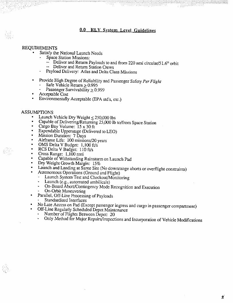
0.0 RLV System Level Guidelines
REQUIREMENTS
• Satisfy the National Launch NeedsSpace Station Missions:
-- Deliver and Return Payloads to and from 220 nmi circular/51.6 ° orbit-- Deliver and Return Station Crews
- Payload Delivery: Atlas and Delta Class Missions
• Provide High Degree of Reliability and Passenger Safety Per Flight- Safe Vehicle Return > 0.995
- Passenger Survivability > 0.999• Acceptable Cost
• Environmentally Acceptable (EPA std's, etc.)
:!:! i ¸ ]
_( _ii,i_H
ASSUMPTIONS
• Launch Vehicle Dry Weight < 250,000 lbs
• Capable of Delivering/Returning 25,000 lb to/from Space Station• Cargo Bay Volume: 15 x 30 ft
• Expendable Upperstage (Delivered to LEO)• Mission Duration: 7 Days• Airframe Life: 100 missions/20 years• OMS DeltaV Budget: 1,100 ft/s• RCS Delta V Budget: 110 ft/s• Cross Range: 1,100 nmi• Capable of Withstanding Rainstorm on Launch Pad
• Dry Weight Growth Margin: 15%
• Launch and Landing at Same Site (No downrange aborts or overflight constraints)• Autonomous Operations (Ground and Flight)
Launch System Test and Checkout/Monitoring- Launch (e.g.,automated umbilicals)
- On-Board Abort/Contingency Mode Recognition and Execution- On-Orbit Maneuvering
• Parallel, Off-Line Processing of Payloads- Standardized Interfaces
• No Late Access on Pad (Except passenger ingress and cargo in passenger compartment)• Off-Line Regularly Scheduled Depot Maintenance
Number of Flights Between Depot: 20
Only Method for Major Repairs/Inspections and Incorporation of Vehicle Modifications
, =, ,
i_ii_iiiii_!_i_i:i:i_!i_i_i_
ilili_iii_iiiiiii_i_i,!!i!iii:iiiii!iii!i!,iiiiii_::iiiilI
iiiiii i ili!iiii !iii":!:i,i_ii!,ili::il
i:i_::?::::i:i:
,!_i:?
?i:ii
iiiiii! ::i_:
_iili:
iii iil::iiill
i:i:!:i
?!:i:i:i:i:i
!:::i:::i:i:!:
iiiiill
iiii!ili!ili!:
iiiiiiiiilil
iiii!iiliill
ii!ii_
!!iiil
iiii!!i_
:!iiiiii
:iiii!i_?i:?
_!iiiiiliii!iiii
iliiiiiiiiiii!i!
iiiiiii!:!Ziiiii
i!iii!iii:!:i:i_
iiiiiiii
iliiiii_iiiiiiii
iiiiiiii
,i!ii!_i_ _:i!_?: .... ,..,,
.: !_:ii:_:_i '::!!i_
Section 1.0 Specific SSTO System Requirements

_i ¸v¸.

NO. PARAMETER QUANTIFICATION I SOURCE
1.0 System Requirements - Baseline Winged Body Vehicle - Vertical Take-Off
1.1 Reference Missions - Space Station Missions - IOC 2006
1.1.1 Launch & Landing Sites
Launch site (day or night)
CLARIFICATION
Existing facilities where
possibleModify facilities where
possible
New facilities as requiredSustained engineering and
logistics support
KSC or Vandenberg Launch at landing site
Landing Site (day or night) KSC or Vandenberg
Existing facilities where
possible
1.1.2 Up Payload (in Cannister)
Payload up weight
Orbit heightOrbit Inclination
Payload envelope dia
Payload length
Payload c.go
1.1.3 Down. Payload (in Cannister)
Payload down weight
Payload envelope dia
Payload lengthPayload c.g.
1.1.4 Payload Attachment toCannister
Standard structural andservices interfaces
Z
Y
XCannister doors
Door opening on pad
Door opening in OPF
1.1.5 Cannister Attachment toPayload Bay Structure
Modify facilities where
possible
New facilities as required
25,000 Ibs
220 nmi, Circ
51.6 degrees
upto 15'-0"
up to 30 feet10 to 20 ft
25,000 Ibs
up to 15'-0"
up to 30 ft'-0"10 to 20 ft
Yes
@ 6, 12, 18 etc inches
@ 6, 12, 18 etc inches
@ 6, 12, 18 etc inches
)rovides torsion capabilityone g capability without
GSE
one g capability with GSE
Standard structural andservices interfaces
Forward supports
from forward face of cannister
from forward face of cannister
from forward facefrom forward face
from forward face
Yes
2Fz
10/27/94 9:49 AM
<i_::!ii<_iil¸:!!i!__!_!i _ill< _iii_i_i!_!_:ii!i !:i:_ii:iii i_i!i!ii_i!ii_i!_!i!__,i_i_:_!_ii_!iiii!iili__!__'iiii_:<_ii!:_i_'_!_ < _i<:<<iii<,i_i:_ili i< :i _:<_<_:!i__i_ii_:i!<<:!'<ii:_iii_:<_::<_i_<ii<i<::i:i!< ii_!i_iii!il,ill_iiii!::ii::ii_!:!i!ili_ii!iliiiiiiii!!ii!iiiii!!!ii!!iiiiiiii_!i!i_!iii!ii!iiiiii_!_i!_i_!iiii_]!i_ii!i_iiiiii_iiiii_!iii_i_iiii_i_iiiiiii!iiiH ,: :< :<:k:: :<A<:_::+T:<::<:><:::: :::9:::::::::<::::::::::::7:::::
• ,<+::::h:ii:i!:!!!i!ii_i:iiiiiiii:iii!ii!_iiiiii:!iliiiii!iiiiii!iiii!!iiii:
RQoments Matrix for Nov 4
NO. PARAMETER QUANTIFICATION2 for both Fz and Fx and
Aft supportsone Fy
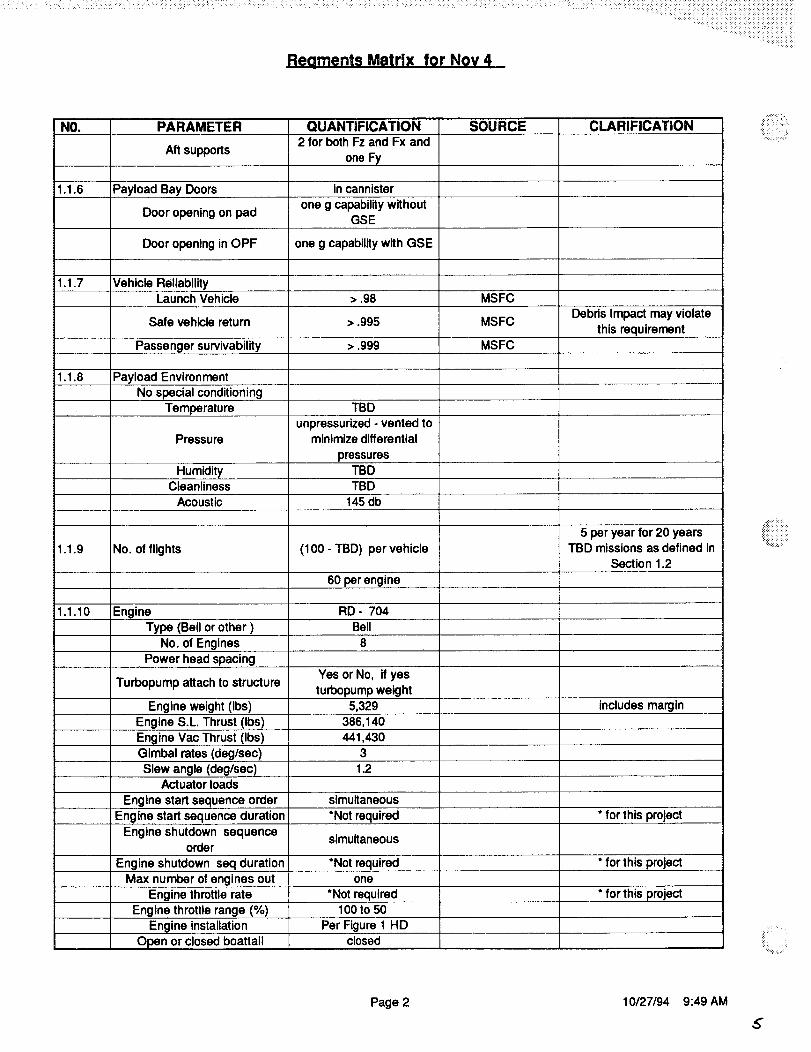
1.1.6 Payload Bay Doors in cannisterone g capability without
Door opening on pad GSE
Door opening in OPF one g capability with GSE
1.1.7 Vehicle ReliabilityLaunch Vehicle > .98
Safe vehicle return > .995
Passenger survivability • .999
1.1.8 Payload Environment
No special conditioningTBD
SOU RCE CLARIFICATION
MSFC
Debris Impact may violateMSFC
this requirementMSFC
Temperature
1.1.9
Pressureunpressurized - vented to
minimize differential
No. of flights
pressures
Humidity TBDCleanliness TBD
Acoustic 145 db
Engine
(100 - TBD) per vehicle
60perengine
1.1.10 RD - 7O4
Type (Bell or other )
No. of Engines
Bell
Power head spacing
Turbopump attach to structureYes or No, if yes
turbopump weight
5 per year for 20 yearsTBD missions as defined in
Section 1.2
Engine weight (Ibs) 5,329 includes margin
Engine S.L. Thrust (Ibs) 386,140
Engine Vac Thrust (Ibs) 441,430
Gimbal rates (deg/sec) 3
Slew angle (deg/sec) 1.2Actuator loads
Engine start sequence order simultaneous
Engine start sequence duration *Not required * for this project
Engine shutdown sequence simultaneousorder
Engine shutdown seq duration *Not required * for this projectMax number of engines out one
Engine throttle rate *Not required * for this project
Engine throttle range (%) 100 to 50Engine installation Per Figure 1 HD
closedOpen or closed boattail
H.::!!;!iiii!!iii:::
!_!iiiii_iiiiii!ii!ii:
Page 2 10/27/94 9:49 AM
5"

Reaments Matrix for Nov 4
NOI
1.1.11
1.1.12
1.1.13
PARAMETER QUANTIFICATIONNo of feeclllne penetrations in
thrust structure 8
Engine removal time on pad NoneEngine removal time OPF
Compliance requirememt
Flight Rate
Operational Life CycleFleet size
*Not required
Vehicle Empty Weight MarginFlight performance reserve
TBD
(5-TBD) missions per year
per vehicle
20 years/vehicle
Maximum Flight rate 3 in 2 weeksMax vehicles In flight @ same
time 2
15%
1.1.14 Vehicle Operating TimePre-launch
Ascent
On-orbit
1% of Delta V ideal
1.1.15
24 hours
0.5 hours3-48 hours nominal
168 maximum
3 days average
docked to station
Re-entry 0.75 hours
7 days
Autonomous Operations
Launch system test and check-
out monitoring
Launch (automated umbilicals
and connections)
On-board abort/contingencymode recognition/execution
On-orbit maneuveringTurn Around Time1.1.16
Shifts 2 shitts/day - 3rd shift for
contingenciesOPF to end On pad processing 12 hours
Maximum Hold Time 12 hours
Depot level inspection 20 flightsOn pad maintenance vehicle-none
payload-none
SOU RCE CLARIFICATION
Return to OPF
* for this project
TBD missions as defined inSection 1.2
3 x (100-TBD)TBD missions as defined In
Section 1.2
No access to Payload after
rollout to pad
Vehicle provides safety stausmonitoring of payload
functions - capability to
direct/relay
telemetry/command withattached and released
payload.
Page 3 10127/94 9:49 AM

Re0ments Matrix for Nov 4
NO. PARAMETER QUANTIFICATION SOURCE CLARIFICATION
Container independently
monitors safety staus of
attached payload and is able
to shut down and make all payload systems safe.
Standardized power and
environment levels suppliedby vehicle throughstandardized interfaces.
Launch on demand 24 hours
1.1.17 Fleet Certification one time Target
1.1.18 Ferry CapabilityLand No
Sea No
Air Yes
1.1.19 Mission Trajectory Table 1T
Thrust to weight @ lift-off 1.2
Delta V On-orbit 1100 fpsMaxg 3
1.1.20 All-Envelope Intact AbortCapability
Propellant dump None
Propellant consumption Yes- through engine burn
Miscellaneous Operations and1.1.21ground Rules
Use of pyrotechnics None
Use of hydraulics NoneUse of corrosive fluids None
Use of hypergolics None
Initial procurement shall1.1.22 Spare Parts
accommodate attrition1.1.23 DDT & E Goal Minimum
Annual Operations cost Goal Minimum
1.1.24 Vehicle Weights and c.g.s Table lW SSD
1.2 Other Missions- 40 K Payload into 150 nm circular orbit. 28.5 degree Inclination
The requirements of this mission are the same as that in Section 1.1 except as delineated in this section
1.2.2 Up Payload (in Cannister)
Payload up weight 40,000 Ibs
Orbit height 150 nmi, Circ
Orbit Inclination 28.5 degrees
1.2.3 Down Payload in (Cannister)
Page 4 10/27/94 9:49 AM
Reaments Matrix for NOV 4
'_!_i_i_i i: NO. PARAMETER QUANTIFICATION
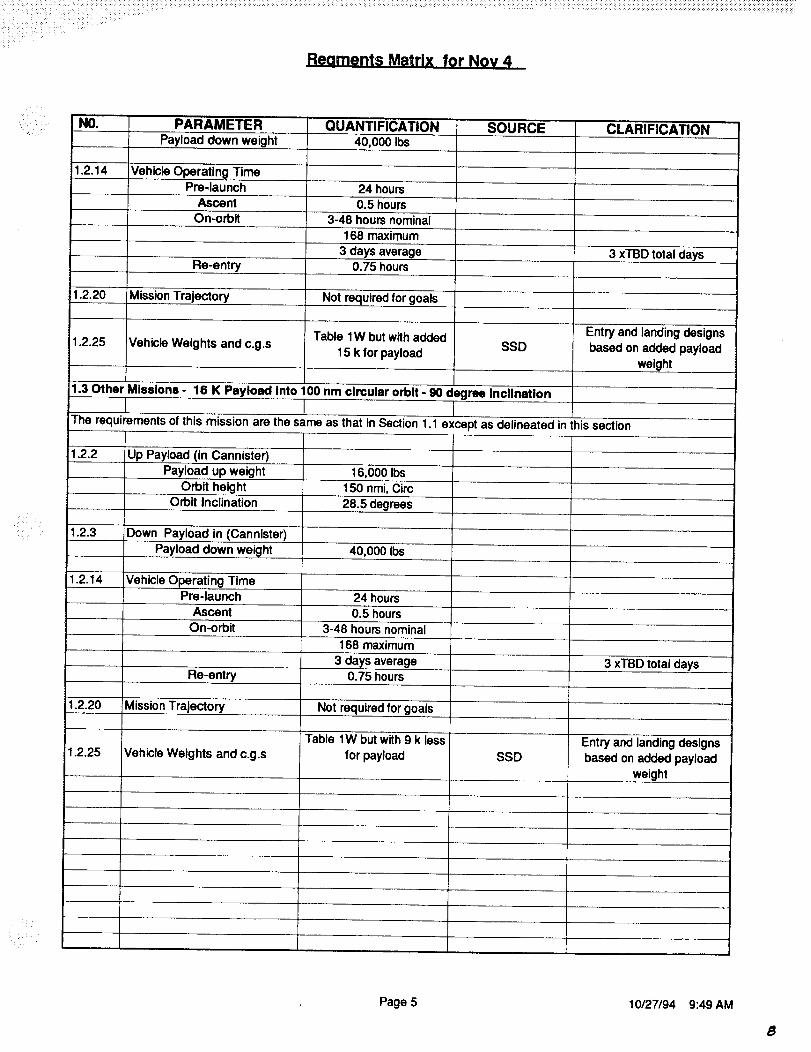
Payload down weight 40,000 Ibs
1.2.14 Vehicle Operating TimePre-launch
Ascent
On-orbit
24 hours
0.5 hours
3-48 hours nominal
168 maximum
3 days average
SOU RCE CLARIFICATION
3 xTBD total daysRe-entry 0.75 hours
1.2.20 Mission Trajectory Not required for goals
Table lW but with added Entry and landing designs
1.2.25 Vehicle Weights and c.g.s 15 k for payload SSD based on added payloadweight
1.3 Other Missions - 16 K Payload into 100 nm circular orbit - 90 degree Inclination
The requirements of this mission are the same as that in Section 1.1 except as delineated in this section
1.2.2 Up Payload (in Cannister)
Payload up weight 16,000 Ibs
Orbit height 150 nmi, Circ
Orbit Inclination 28.5 degrees
1.2.3 Down Payload in (Cannister)
Payload down weight 40,000 Ibs
1.2.14 Vehicle Operating TimePre-launch
Ascent
On-orbit
Re-entry
24 hours
0.5 hours
3-48 hours nominal168 maximum
3 days average0.75 hours
1.2.20 Mission Trajectory Not required for goals
1.2.25 Vehicle Weights and c.g.sTable lW but with 9 k less
for payload SSD
3 xTBD total days
Entry and landing designs
based on added payload
weight
Page 5 10/27/94 9:49 AM
8

:i:i i.i_i:!! i_i:]:i_:!i::_i:i
•:,:.:::::: ,:: ,:;
iiiii_ili!i!!i_ii:ii!ii_i_
iiiiii!iii_i_i}i_i_iill_
_i_: i,
ii__.ii:__
:::_::
i!iiiiii!i!ii!
iiililiii :i
!ii_illi_iiii!_ii:i:?i3!i]iiill
'i_iii
HI.,

Section 2.0 SSTO Vehicle Descriptions


Reoments Matrix for NOv 4
NO. PARAMETER QUANTIFICATION SOU RCE
2.0 SSTO Vehicle Configuration Deecri )tlon 2A
2.1
2.1.1
Configuration 2A Drawings
Vehicle Weight Statement
2.1.2 Vehicle DescriptionUllage volumes (%)
Tank materials
Feedline materials
Forward fuselage, Intertank,Wing, and Tail structures
materials
Thrust structure baselinematerial
TPS
RCS propellants
OMS propellants
Vehicle Management system
Navigation and Guidance
System
Communication/NAV AIDS
Remote Interface Units
Residuals LH and LO tank
Residuals 0g tanksEngines
I
2.2 !Configuration 1A Drawings
2.2.1 Vehicle Weight Statement2.2.2 Vehicle Description
Tables 1W
4 % in alltanks
AI-Li for LO tank, IM7/977-2 baseline for LH
AI-LI for LO tank,
Composite for LH tank
Gr/BMI baseline
IM 7/977-2 baseline
Baseline designs- AFRSI
(to 1400 F), TABI (to 2000
F), and AETB to (2600 F)LH and LO
LH and LO
CPU Processors/Racks @
3 MPS 3 Reqd, Remote
Processors 8 Reqd,Fiberoptic Bus System,
Discrete Wiring, VCntrl Bus
Triple Redundant, Mission
Dig. Processor 2 Reqd,
Mass Storage
INS/NAV-GPS 3 Reqd,
GPS Antennas 3 Reqd,Laser Air Data, Radar AIt
System, Navigation Base
UHF System, S-Band PCM
& Pwr Amp 2 Reqd, S-
Band Ant 4 Reqd, S-BandTrmttr, TDRSS
Main Engines, AeroSurfaces, RCS, Fuel Cntrl,
Doom, Gear Doors0.5%
3%
CLARIFICATION
LO tank forward - integral LCand LH tanks
RD - 704 (eight) Data from Pratt and Whitney
Table 1Eng
Table 2W
same as for 2A
Page 6 10/27/94 9:49 AM

Reoments Matrix for NOV 4
'::::: :i_i:!:ilSi;i!:i;::__'_i::iii:i ::iii: :!
NO. PARAMETER QUANTIFICATION
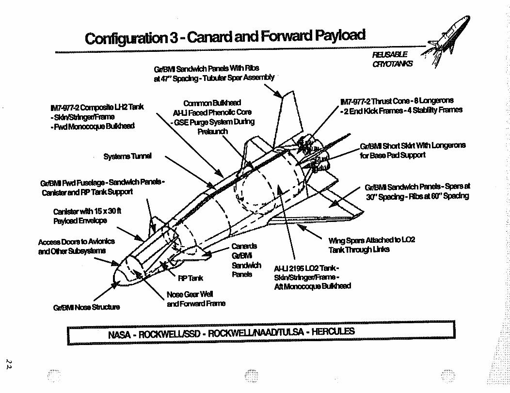
2.3 Configuration 4 Drawings
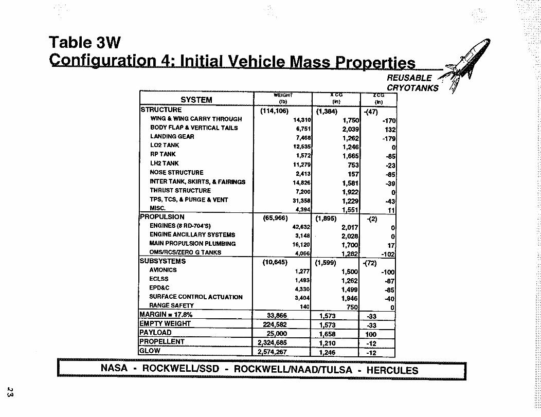
2.3.1 Vehicle Weight Statement Table 3W
same as for 2A - except for
2.3.2 Vehicle Description common bulkhead whichuses AI-Li
2.4 Configuration 3 Drawings2.4.1 Vehicle Weight Statement Table 4W
same as for 2A - except for2.4.2 Vehicle Description common bulkhead which
uses AI-Li
SOU RCE CLARIFICATION
Page 7 10/27/94 9:49 AM

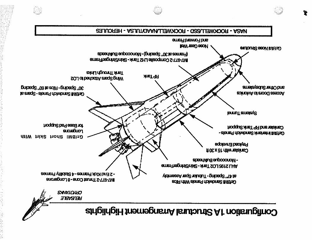
Vehicle Configuration 1A - LO2 Tank Aft
All Flying V-TailsContribute to both pitch and yawstability and control (all speeds). Aft RCS
REUSABLECRYOTANKS
Short-Skirt (Hold-Downs)
Aft LO Tank (Integral)
Main Engines (RD 704)Thrust through tanksfor efficient design.
ust Structure
Payload BayLocated on top for operations,midship for CG In/out control."'--_j_
\\
\ Body FlapProvides trim control.
Forward LH Tank (Integral)
Nose Ramp(and Airfoil)
Defined fornose-up
Wings
RP Tanks
Power SystemsEnvironmental Control
Attached to tank and thrust structure.
\
AvionicsRCS/OMS
Located In nose forCG control.
_--_-0--_- Kcw_,usso""""oc,WF"'J"AAorru,S'A.............................: ._,cu,_s ".......Inrrr nnrnll ,.,, ........ . ........................ , ..............
_ii '_i_:_i!ili
i!iiii!
ii!ii_ii
iiii_iii_iiiiiill
..
....
.._.....

i!i_:!I!I/I_i_!i_¸
ii :_i_ " _
- _ !::::̧ _ i,
"i! ¸ i_:::i _ , ..... _:......_.i.............. _:i_i_i......... _:_i!i_i:._i__:_ 4
F s_.nou_"' vs.o_,o,,,,,n._M.oo_-assm3,,oou__!____vSv,...............................I
/_, S)INVIOA IdO =
.R"IBVSI'I._Id
uo,lonpaEI lull,aM leJn:lonJ:lS :VI. uot:leJn6,._uo. . . o
i_ _i_
_i _ _
ii!!_i_i_i___'
_ii'_ i__i_ii_
-_Pmii_O'lG61ZRi_
_ql q6o_JqLu_
P_-eW0u_d _n_
pu_u.mw_
_d_qUe, dU puuqqu_-ePUedq_pu_- )F_q_q 1_9
_(kk_ pedeseG_ol
_ua__S_.__ pu_-

,¢
Table 1W _J• " " "" "
WEIGHT X CG ZCG
.... SYSTEM .............. (,b) .......... (_) ....... (in)
STRUCTURE (116,071) (1,273)
WING & WING CARRY THROUGH 14,243 1,712
BODY FLAP & VERTICAL TAILS 6,751 1,961LANDING GEAR
LO2 TANK
RP TANK
LH2 TANK
NOSE STRUCTURE
7,468
9,622
1,484
10,979
2,025
1,163509
978
1,560125
INTER TANK, SKIRTS, & FAIRINGS
THRUST STRUCTURE
TPS, TCS, & PURGE & VENT
MISC.
PROPULSION
ENGINES (8 RD-704'S)ENGINE ANCILLARY SYSTEMS
MAIN PROPULSION PLUMBING
OMS/RCS/ZERO G TANKS
;SUBSYSTEMS
AVIONICS
ECLSS
EPD&C
SURFACE CONTROL ACTUATION
RANGE SAFETY
MARGIN : 17.95%
EMPTY WEIGHT,,,, ,.,r,,,,,,,
PAYLOAD
20,328
7,392
31,694
4,086
(63,712)42,632
3,046
14,402
3,631
(10,618)
1,277
1,485
4,320
3,397
140
341180
224_582
25r000
PROPELLENT . _ 2,324,685
1,145
1,874
1,133
1_,149
(1,849)
1,967
1,978
1,711
910
(1,278)750
870
1,098
1,897
960
11466 -43
1_466 -43978 112
"627 " _ -16
-(SS)-200
118
-197
-6
-100
0
-56
-52
0
-49
-1
-,(13)0
0
-31
-114
-.(78)-100
-87
-88
-56
0
GLOW 2,574,267 703 -17
I NASA- ROCKWELUSSD - ROC_ELL/NAAD/TULS A - HERCULES I
_: :i:i:ii_̧
i:i_!'_!:::_!:_i:il
_!ili:i:i(__i,!_i_!iiiiiiii!iiii
_i;i::i:::i: :_:i_i::_::i_i:i:!:i:?

Table 1W1 - Propellant Weight For Specified Load Cases
LOAD CASE NUMBER
2A-3.2.1
2A-3.2.2
2A-3.3.1
2A-3.3.2
2A-3.4,1
2A-3.4.2
2A-3.5.1
2A-3.5.2
2A-3.5.3
LOAD CASE DESCRIPTION
Prelaunch - Unfueled - wind from front
Prelaunch - Unfueled - wind from back
Prelaunch - Fueled - wind from front
Prelaunch - Fueled - wind from back
Lift-off - wind from front
Lift-off - wind from back
FUEL TANK WEIGHTS
LH2 TANK LOX TANK RP TANK
(Lbs)0
(Lbs)
0 0
183456
(Lbs)
0
1900444 221946183456 1900444 221946
183456 1900444
183456
221946
1900444 221946
143743 1361670 138549
2A-3.8
2A-3.11
2A-3.12
2A-3.13
2A-3.14
Max q AIpha- positive angle of attack (4 Degrees)
Max q Alpha - negative angle of attack (4 Degrees)
Max q Beta - positive angle of attack (4 Degrees)
Max Thrust - angle of attack is zero
TAEM Maneuver 2.5 g
Main Gear Landing - Spin-up
Main Gear Landing - Springback
Nose Gear Landing - Slapdown
143743 1361670
143743 1361670
138549
138549
99850 766184 46373
917 9502
9502917
917 9502
1110
1110
1110
917 9502 1110
Page 1

¢-
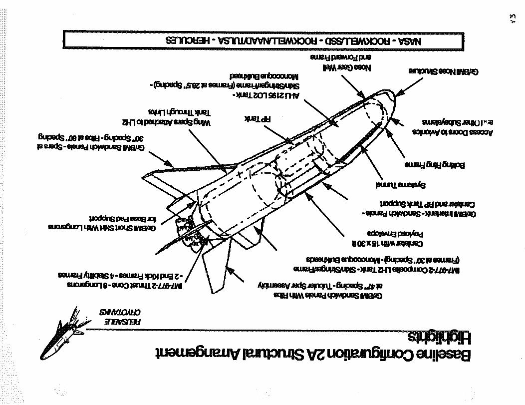
Vehicle Configuration 2A- LO2 Tank Forward ....j
..............................................All Flying V-Tails
Contribute to both pitch and yawstability and control (all speeds).
Short-Skirt (Hold-Downs) _
Aft LH Tank (Integral)
Aft RCS
Main Engines (RD 704)
Thrust through tanksfor efficient design.
Payload BayLocated on top for operations,midship for CG In/out control.
Forward LO Tank (Integral)
\
\
\
Thrust Structure
Body FlapProvides trim control.
Nose Ramp(and Airfoil)
Defined for
WingsAttached to tank and thrust structure.
AvionicsRCS/OMS
Located In nose forCG control.
RP Tanks
Power SystemsEnvironmental Control
k NASA- ROCKWEL_SSD - ROCKWEL_NAAD-_ULSA- HERCULES
i
_i:i:iiii!il!:i,i:
ii!iiiiii_:
!_ii_::: ,
_iiiii:_i_:i:_:_i:!i_,:i_
I. s31nOU3H" vslnJJeVVNm3M_oou- GSS-m3M___O_OU----VSV._
u6!saQ Nuel leJ6alUl •Nuel H'! gV •
Nuel 01 pJeMJo=l •
eSelesn=l Jm,eme!o J,OO=l-i:_:
_,daouooaU!leseE!:V_uo!3,eJn6guo0....!
!:!!::i!i!/_::iii_:_:i:_i:!:::iij _ :: !:i i: ¸
iiil I i ii_ ii_i: i:i:
!i?i:i :i!, i?
!!iiiii!i!_?iiii_'iii _ :i:_
:+
:i?:_!i,:ii:::: _ +
:: :i i::
!:?!_i::iil
:i!?
squnq_qUel_(n_p_m_vs_ds_
\
#oddn_ ped e_El_
qllM IJl)lS |Joqs IINE]/'E)
• \\
\
smieJ-jAII_ _- smue_ _DI ptr__:-_ e- euo"JP;mq.L_-Z/.6-ZI_I
__bo_o_.s_m_ums- _i _n S6_ rtN
sp46gq6!H _ leJnzon.q_V I.uo.qmn6gl.mO

Table 2W
REUSABLE ,_..p,_ vCRYOTANKS /,_
WEIGHT X' CG _ZC;G
SYSTEM
STRUCTURE
W1NG& WING CARRY THROUGH
BODY FLAP & VERTICAL TAILS
LANDING GEAR
LO2 TANK
RP TANK
LH2 TANK
NOSE STRUCTURE
(Ib)
(114,138)
14,243!
6,766
7,468
9,38(]
1,538
11,358
2,187INTER TANK, SKIRTS, & FAIRINGS
THRUST STRUCTURE
TPS, TCS, & PURGE & VENT
MISC.
PROPULSION
ENGINES (8 RD-704'S)
ENGINE ANCILLARY SYSTEMS
MAIN PROPULSION PLUMBING
OMS/RCS/ZERO G TANKS
SUBSYSTEMS
AVIONICS
ECLSS
EPD&C
SURFACE CONTROL ACTUATION
RANGE SAFETY
MARGIN = 19.%
EMPTY WEIGHT
PAYLOAD
PROPELLENT
GLOW
(63,837)
(10,753)
351854
2241582
251000
21324,585
21574,267
17,343
7,784
31,692
4,380
42,632
3,330
14,199
3,676
1,277
1,528
4,370
3,438
140
(_)
(1,383)
(1,930)
(1,465)
11573
11573
11250
(in)
-(53)1,780
2,052
1,201
1,742
1,259
650
132
1,346
1,944
1,239
1_356
2,047
2,0571
1,778
1_058
1,050
1,217
1,291
1,960
1_200
-200
104
-161
0
-100
-9
-66
-46
0
-43
-16
-(12)
0
0
-23
-112
-(72)-100
-87
-85
-41
0
-40
-4O
90
11583 .... ":!3
1,579 -14
............. ' .... _- ........ Innn1'............ ' .................................. • ............................... mm
NASA - ROCKWELIJSSD - ROCKWELL/NAAD/TULSA - HERCULES II " _............... 111........... •..................................... nnnnrr...............111'"i....... ,, nrr'""r.... I....M
:r::::!::_:ii•iiii_!¸
i!ii_iiiii!!_i_i_i_I

__,i:i.i,!_,_:,:i_!!_'!_-:::
iiiiii!!iiiiiiiiii!iiii_!i_iii!ii_''iiiiiiiiii_i: _:Z!!:::i_i?
i_i_i_i_/_i_i%_
:if::!: : i::
i!i/__iiiil
iiiiil,iiii_'_i,!i!,i'_.ii_ii
......................s37n0U3H - VSTn.uoVVNn73M_o0U___-assn!_M__oou - VSVN........................_1
s6u!M
'lOJ|UOOO0
Jo| esou Ul petBoo"l
IOJ_,UOO le],uetuuoJ!AU3stue_,s_s JeMOd
Nuel dEI
\
\\
SINO/SOUso!uo!AV
°tuo dn-esouJo#peuHeo
(I!op!v pue)duJeEI eSON
-....
(leJ6e_,ul))lUel H7 pJeMJo-i
eJ n],onJ],S ],snJql peeqNIn8 uommoo
(leJ6e_,Ul) Hue1 0"1 gV
•USlsap _,UelOlge Jo_.._u_ ._n_4_ _s_4_ (SU_OQ'PlOH) ]JPiS':IJoqsUTOL QEI) seu!ou3 u!elN
'(speeds lie) IOJlUOOpue A4111qm,s
S_)U _JV _eX pue qolld qloq o| einqp_uoo
peol_ed pJeMJO::lpue pJeueo ............g-----uo_n6!tuoo

::ii̧•
_:i :i::i :iiI
_4r'smdm-_spar_
W._Z-2ThrustCone-e_-2 EJldKickFrames-4 Slall_y Frames
_Tumd
:w___ea_PadStm_
e._ p_d_xjo- Smdw_Panl-Ca_WmdRPTmkStm_
A(_ss DoomtoAviorlcsendOl_rS.bsym_
Gnl_ NoraSImctum
\
tI
\ G.I_ Sandw_Pm_-Srmel
Wt_jSpamAaachedtoLO2Tn_U,_
.......... PPMMMM ' 1"II'"P"Pr ' ....................... ".............. "'_ ...... ""' ............................ -........ ---_"
i .I:K)(:XWELL/SSD- -H_ I.................. • ,,,,,'1 .... '"11 ........... PPM_ "11
_!iiiil;:! _i!ii!
..... ,, • H.
Uo
Table 3W JREUSABLE f,P,_ v
wE,c_ xc_ ...........zc. 'CRYOTANKS /'7SYSTEM
STRUCTUREWING & WING CARRY THROUGH
BODYFLAP& VERTICALTAILSLANDINGGEARLO2TANKRPTANK
LH2TANK
NOSESTRUCTURE
INTERTANK,SKIRTS,& FAIRINGSTHRUSTSTRUCTURETPS,TCS, & PURGE& VENTMISC.
PROPULSION
ENGINES(8 RD-704'S)ENGINEANCILLARYSYSTEMSMAINPROPULSIONPLUMBINGOMS/RCS/ZEROG TANKS
SUBSYSTEM SAVIONICS
ECLSS
EPD&C
SURFACE CONTROL ACTUATION
RANGE SAFETY
MARGIN = 17.8%
EM PTY WEIG HTPAYLOADPROPELLENTGLOW
............. (Ib) ..... (in)
(114,106) (1,384)14,310
6,751
7,468
(6s,sss)
(10,645)
33_8662241582
25r000
12,535
1,572
11,279_2,413
14,8267,200
31,358
4,394
42,632
3,148
16,120
4,066
1,277
1,493
4,330
3,404
140
(1,895)
(1,599)
1_573
1_573lr658
1,7502,0391,2621,2461,665
753157
1,5811,9221,229
lt551
2,0172,0281,7001_282
1,5001,262_1,4991,946
750
2,324,685 ............1,210...2,574,267 !,246
(in)
-(47)-170132
-1790
-85-23-85
-390
-4311
-(2)00
17-1021
-(72)-100
.87.85-40
0.33.33100
-12-12
i " " " _-........... "...................... 1NI'I"ll ....... MMIII.......... 1'''_ ...... "'"" ........................ MMII..........NASA - ROCKWELL/SSD - ROCKWELL/NAAD/TULSA - HERCULES11"1 .......
M
IMMr'r............. q' I
:•ii_!i_!i_i!il•ili__'"_i__Iii_!i!i_iiii,?i_i!i
/:i,!ii
tJ
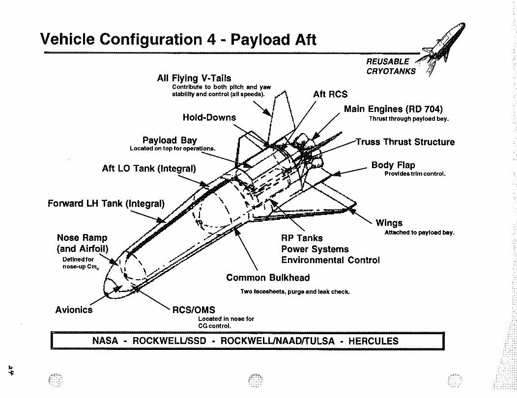
Vehicle Configuration 4- Payload Aft REUSABLECR YO TANKS
All Flying V-TailsContribute to both pitch and yawstability and control (all speeds). Aft RCS
Hold-DownsMain Engines (RD 704)
Thrust through payload bay.
Payload BayLocated on top for operations.
Aft LO Tank (Integral)
Thrust Structure
Body FlapProvidestrim control.
Forward LH Tank (Integral)
Nose Ramp(and Airfoil
Defined for f %nose-up Cm o
\
\Wings
RP Tanks
Power SystemsEnvironmental Control
Common Bulkhead
Attached to payload bay.
Two facesheets, purge end leak check.
Avionics RCS/OMSLocated in nose forCG control.
I ............NASA - ROCKWELIJSSD - ROCKWELIJNAAD/TULSA - HERCULES
iii_il!i_:i
!:iii
_iiil :-:iii!ii:iiii
. H
• ,H •
•_i!ii_i!_iii!iiiili_!i_iiiiiiiiill

:L i
,_h • i _
:ii7: ¸¸ _ •
i_iii_:i__' _,i _:i_i_ i_
u6!sao Hue1 leJ6alUl •
Hue1 H1 pJeMJO_ •peeqNInEi uotutuoo
'Hue1 0"1 P!tN •
q|6uel eoueJelaEI 1oo=1-9"08 _ _v I
I
_ j e6elesn=l Jeletue!(] lOO:l-tO
/_'/ S_INVJ.OJildO
._'IBVSli._EI
aJnionJlS lsnJq.L ssnJ/ 17uo!leJn !tuo 0
((iiiil/<
ii ¸ ih)
; i_ /

,3
'iii_ , _.!_
i!ii!!_i!i_i_i_
i" I
__H'W ...... -OSSn'BM,W:_ I_ e,-,booo,x_p,_ - Coup_ls mu.,m.j_ pue
,_]esaue.a-j) _ Ila_.meOeeON u'qon_ won IININ.m)lUe.Lig.f'l e_XklX)O _-LL.B-,t.IAll
s_Je._je6elBenl_#o_.m,_q_eaiq,x)os_edse_a
eupe,:_,.09_e_q_-eum,:_.,0(:]ese,:ls- slaUed_ IAIB/.m
U.LdI::!
p,:xk_peaeeee.,,__qp,_pl_ poq_ IININ_
,_I.LpueslaUecl]rmoeo_ qlI/V_em'qon._]m'Uql.ssru.L_-Li..B-LINI
_.mqlopu_u_u:_V cquax_3u_oaV
w_un.L_
S_Lll_!lq_..H_Jetu_ue.u_ _rq_cu_ _ uo.q_nF_Jo,3

Table 4W jREUSABLE ._r.p_ vCRYOTANKS /,//
WEIGHT _ X"C_,' zCGSYSTEM
STRUCTURE
WING & WING CARRY THROUGH
BODY FLAP, VERTICAL TNLS, & CANARDLANDING GEAR
LO2 TANK
RP TANK
LH2 TANK
NOSE STRUCTURE
INTER TANK, SKIRTS, & FAIRINGS
THRUST STRUCTURE
TPS, TCS, & PURGE & VENT
MISC.
PROPULSION
ENGINES (8 RD-704'S)ENGINE ANCILLARY SYSTEMS
MAIN PROPULSION PLUMBING
OMS/RCS/ZERO G TANKS
SUBSYSTEMS
,,(!,b!...........(113,535)
14,3o_
9,023
7,465
12,76o
2,502
11,o5o
646
14,746
7,588
28,662
4,785
(62,607)
42,632
3,046
13,337
3,592
(10,941 )
(_)
(1_9S)
(1,773)
(831)
1,647
1,599
1,151
1,608492
1,106
64
870
1,821
1,249
904
1,917
1,928
1,692
239
(_)
-(56)-200
88
-163
0
-100
-4
-46
-57
0
-61
-39
-(4)
0
0
3
-741
-(31)AVIONICS
ECLSS
EPD&C
SURFACE CONTROL ACTUATION
RANGE SAFETY
1,277
1,448
4,278
3,799
140
20_
15:
478
1,703
750
-100
-53
18
-56
0MARGIN = 20.%
EMPTY WEIGHT
PAYLOAD
PROPELLENT
GLOW
371499
2241582
25_000
...2.,.324,68S
2,574,26.7 ........
lf430 -37
11430 -37428 0
1,426
1,416
-11
-13
i ....................NASA -ROCKWELIJSSD-..........................................................ROCKWELLJNAADrTULSA-___ .............HERCULES""""rr""rr..............._........... ,rI.......................... . .................................. . ........................... ,_,,,_..._ ..... , .....................................
,ii!:i,

peolAecl pJeMJO=l pue pJeueo
g uo!_eJnlSguoo
uop.onpe_! _,qS!eM leJm,onJ;s _ .-. i_- ]_'" " '
1_uo!:leJn6guoo _-0 TI I1/
_,deouoo eU!lese8 __
Vg uo!leJn6guo3 _
S)INVIOAI:IO
3"IBVSI'I_RI:t .................................................................
uos!JeduJoo uo!leJn6!luoo alo!qaA

!!i i
!_i!i
,>i
i::!
i_ii!i:i!i
i? _,
iliii _
i: :'
?:_?i_i_>i,i/,ii: _ :_ i.i: _
::i_: _i'> _ ,/_
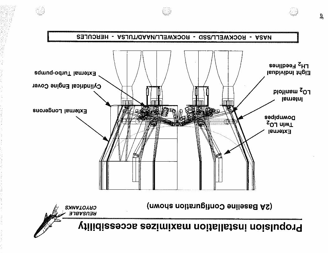
uogellelSUl V L
seullpee.-I i:H-I
l._ seu!lpeed _01!L_._j _:..._..--_::._/r i.....:_------_.
//' S)IN'd.I.OAklO Z I I-/._f_
/_.,_,,,.u_ [ / sau{IPea_-{tueis_s Uo{slndOJd
:::: 7, : :i;
: Z ::: i _
_iii::iii_i_:::ii
s37nOU3H " vs7n_aV-VN_73M)IOOU " assr173M)l°OU_______v_S_VN........i..........]
sduJnd-oqJnl leuJelx3
JeAO0 eU!6U=I leo!JPU!lf0_
suoJe6uo'l leuJelx3
seu!lPee.-I ;OH7lenp!A!PUl 1q5!3
PlOj!uetu _O7
leuJelul
sedlduMoQ_0"1 u!Ml
leuJe_3
Pc)
S_NWO,_UO (uMoqs uo!leJnS!_uoo eu!lese8 V_)
3"iB'VSI'I31:I
_,lllqlsseooe sezluJlxeuJ uolie II:lesu= uols.IndoJ d... . . . .
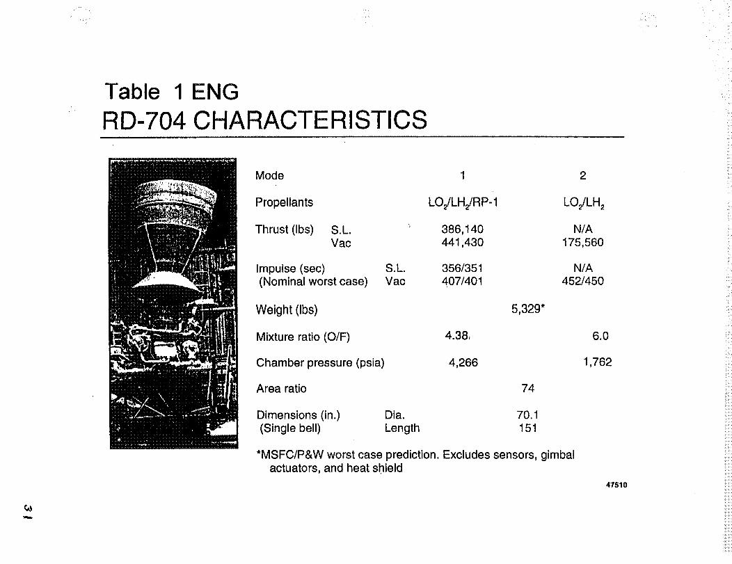
Table 1 ENG
RD-704 CHARACTERISTICS
Mode
Propellants
Thrust (Ibs) S.L,
Vac
Impulse (sec) S.L.(Nominal worst case) Vac
Weight (Ibs)
Mixture ratio (O/F)
Chamber pressure (psia)
Area ratio
Dimensions (in.) Dia.
(Single bell) Length
1
LOJLH2/RP-1
386,140441,430
356/351
407/401
74
70.1
151
*MSFC/P&W worst case prediction. Excludes sensors, gimbalactuators, and heat shield
2
LOJLH 2
N/A
175,560
N/A452/450
6.0
1,762
47510
iiii_
_!ii,i
_iill

iliiiiiii_!_!!i!!ii<<ii:_!ii!_iii%_!i!i_i,!:ii_;:ti_ ::i:it!t
_i!!i¢.k_iiin<_ ¸ •
• -+x+_..
Section 3.0 Structure/TPS Requirements - Roll Out to Pad to return to OPF
],r ,I

_:i_,- i_ii_:_:::_:::_:::,::yiiii!

• ••• •i •• ;i ¸•_
Reoments Matrix for Nov 4
!iii_!'i: • NO. PARAMETER
3.3.6 Fueling Sequence
LO tank fueling rate (gpm)
QUANTIFICATION
LH tank first - LO next
LH tank fueling rate (gpm)
LO tank drain rate (gpm) 3000
LH tank drain rate (gpm) 5000RP tank fueling rate (gpm)
RP tank drain rate (gpm)
3.3.7 Tank Pressurization
Sequence of pressurization
LOtank minimum (psig)
LO tank max relief (psig)
LO peak operating (psig)
LH tank minimum(psig)
LH tank max relief (psig)
10,000
15,000
2000
5OO
SOURCE CLARIFICATION
see design criteria - sect4.6.3
Allows LoadingIn Re__sonable Time
_r
constrained per criteria see design criteria - sect4.6.3
>0
2018
>0
34
32LH peak operating (psig)
RP tank minimum (psig) >0
RP tank max relief(psig) 20RP peak operating (psig) 10.3
160
160
160
0
GH2 pressuriz Temp (Max °F)
GO2 pressuriz Temp (Max °F)
GHe pressurization Temp (Max
°F)
3.3.8 Permissible LeakageLO tank
LH tank
RP tank
3.3.9 Maximum Boil-Off Rate
LO tank (Ib/sec)
LH tank (Ib/sec)
!Pad Environment3.3.10
Coldest temperature 19 F, Mean Min 48 F
Mean Real Humidity 07Concurrent humidity 89.3, Mean Relative
Humidity 13 60.8
Concurrent dew point Mean dewpoint Temp 50 F
Hottest day98 F Max temp, Mean Max
90F
Mean Real Humidity 07
88.4, Mean Relative
Humidity 13 63.9
Mean dewpoint temp 77 F
Concurrent humidity
Concurrent dew point
propulsion requirements only- see Table 1 TP for
propulsion requirement s only- see Table 1 TP for
propulsion requirements only- see Table I TP for
Max Allowable During
Replenish Operation
Page 10 11111194 11:36 AM
32-
Reoments Matrix for Nov 4
......._:_i_ii:iii_i:
NO. PARAMETER QUANTIFICATION SOU RCE CLARIFICATION
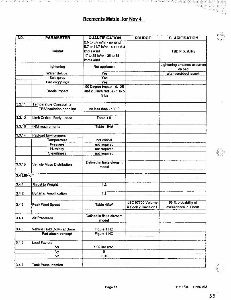
Rainfall
2.5 to 5.5 in/hr - no wind5.7 to 11.7 in/hr - 4.4 to 8.4
knots wind
17 to 25 in/hr - 35 to 55
knots wind
TBD Probability
lightening Not applicable !Lightening arresters assumec_on pad
Water deluge Yes after scrubbed launchSalt spray Yes
Bird droppings Yes
90 Degree impact - 0.125
Debris Impact and 2.0 inch radius - 1 to 5ft Ibs
3.3.11 Temperature ConstraintsTPS/insulation bondline no less than - 160 F
3.3.12 Limit Critical Body Loads Table 1 IL
3.3.13 IHM requirements Table 11HM
3.3,14 Payload Environment
Temperature not critical
Pressure not required
Humidity not required
Cleanliness not required
Defined in finite element3.3,15 Vehicle Mass Distribution
model
3.4 Lift- off
3.4.1 Thrust to Weight 1.2
3.4.2 Dynamic Amplification 1.1
JSC 07700 Volume 95 % probability of3.4.3 Peak Wind Speed Table 4GW
X Book 2 Revision L exceedance in 1 hour
Defined in finite element3.4.4 Air Pressures model
3.4.5 Vehicle Hold Down at Base Figure 1 HD
Pad attach concept Figure 1 HD
3.4.6 Load Factors
Nx 1,32 inc ampl
Ny 0Nz 0.013
3.4.7 Tank Pressurization
..::!:i!iiii::
Page 11 11/11/94 11:36 AM
33

NO.
3.4.8
3.4.9
13.4.10
3.4.11
PARAMETER
LOtank minimum (psig)
LO tank max relief (psig)
LO peak operating (psig)
LH tank minimum(psig)
LH tank max relief (psig)
LH peak operating (psig)
RP tank minimum (psig)
RP tank max relief(psig)
RP peak operating (psig)
GH2 pressuriz Temp (Max °F)GO2 pressuriz Temp (Max ° F)
GHe pressurization Temp (Max° F)
Permissible LeakageLO tank
LH tank
RP tank
Maximum Boil-Off Rate
LO tank
LH tank
Pad Environment
Coldest temperature
Concurrent humidity
Concurrent dew point
Hottest day
Concurrent humidity
Concurrent dew point
Rainfall
lightening
Water deluge
Salt sprayBird droppings
Debris impact
Temperature ConstraintsTPS/insulation bondline
QUANTIFICATION
20
15.3
15.3
34
32
1
20
10.3160
450
160
TBD
TBD
TBD
0
19 F, Mean Min 48 F
Mean Real Humidity 0789.3, Mean Relative
Humidity 13 60.8
Mean dewpoint Temp 50 F
98 F Max temp, Mean Max90F
Mean Real Humidity 0788.4, Mean Relative
Humidity 13 63.9
Mean dewpoint temp 77 F
2.5 to 5.5 in/hr - no wind
5.7 to 11.7 in/hr - 4.4 to 8.4knots wind
17 to 25 in/hr - 35 to 55
knots wind
50 kiloamperesYes
Yes
Yes
No
no less than - 160 F
SOURCE CLARIFICATION
propulsion requirements only- see Table I TP for
propulsion requirements only- see Table 1 TP for
propulsion requirements only- see Table I TP for
TBD Probability
TBD Probabilityafter scrubbed launch
Page 12 11111194 11:36 AM
3_

Reoments Matrix for Nov 4
NO.
3.4.12
3.4.13
3.4.14
PARAMETER QUANTIFICATION
Limit Critical Body Loads Table I IL
Dynamics
SOURCE CLARIFICATION
Acoustics (db) Table 1 and 2 AC
Nx amplification 1.1 Engine gimbal transients, ancNy 1.05 unsteady engine flowNz 1.05 transients
Ignition over pressure TBDPOGO TBD
Guidance and Control
Elevons
Body FlapTail
Main engine
Fixed orientation at TBD
Fixed orientation at 0 deg
Actuator loads TBD
Gimbal angles TBDActuatator acceleration TBD
Actuator rate TBD
3.4.15 IHM requirements Table IlHM
3.4.16 Payload Environment
Temperature not required
Pressure not requiredHumidity not required
Cleanliness not required
3.4.17 On Pad Abort
Engine shutdown TBD
Sating TBDReinstallation of holddowns TBD
Definedinfiniteelement
modelVehicle Mass Distribution3.4.18
3.5 Ascent - Max qa - at T=76 secs
3.5.1 Thrust to Weight 1.78
3.5.2 Dynamic Pressure 560 500 nominal + 60 dispersed
3.5.3 Angles of Attack
positive alpha 4
negative alpha -4
positive beta 4
negative beta -4
3.5.4 Air Pressure Distribution Differential pressures basedon 1.0 psi
_!!!i!!i_:!!i::
:ii_i!:i:!
Page 13 11111/94 11:36 AM
35
Reaments Matrix for Nov 4.
_ii_ii!i_ NO. PARAMETER
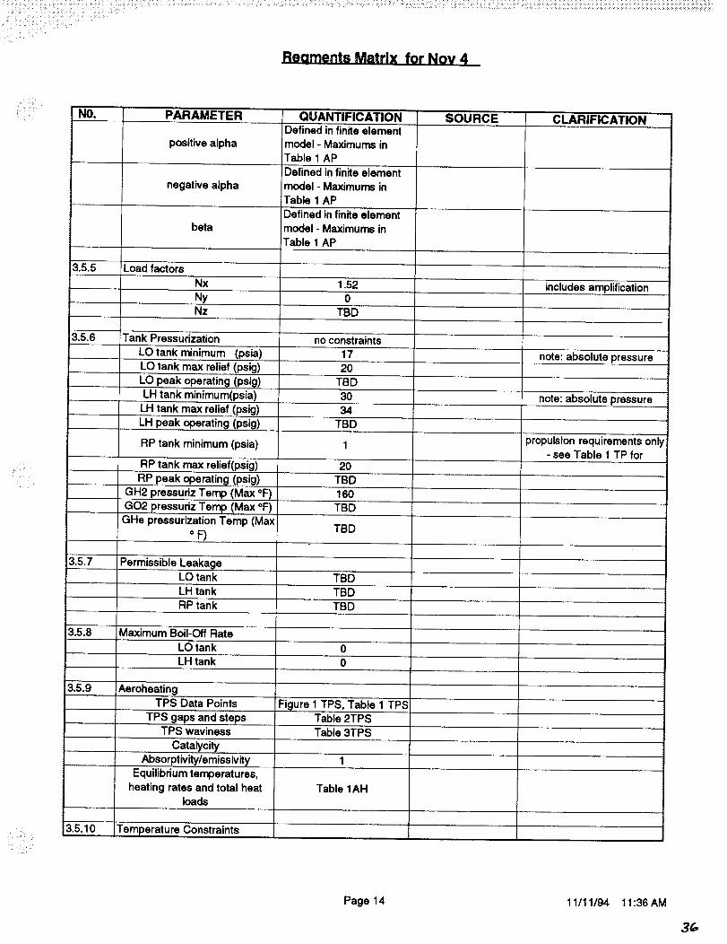
positive alpha
negative alpha
beta
3.5.5 Load factors
Nx
NyNz
3.5.6 Tank Pressurization
LOtank minimum (psia)
LO tank max relief (psig)
LO peak operating (psig)
LH tank minimum(psia)LH tank max relief (psig)
QUANTIFICATIONDefined in finite elementmodel - Maximums in
Table 1 AP
Defined in finite element
model - Maximums inTable 1 AP
Defined in finite element
model - Maximums inTable 1 AP
1.520
TBD
no constraints
17
20
TBD30
34
LH peak operating (psig) TBD
RP tank minimum (psia) 1
RP tank max relief(psig) 20
RP peak operating (psig)
GH2 pressuriz Temp (Max °F)GO2 pressuriz Temp (Max °F)
GHe pressurization Temp (MaxoF)
3.5.7 Permissible LeakageLO tankLH tank
RP tank
Maximum Boil-Off Rate
LO tank 0
3.5.8
3.5.9
3.5.10
Aeroheating
LH tank
TPS Data Points
TPS gaps and stepsTPS waviness
Catalycity
Absorptivity/emissivity
Equilibrium temperatures,heating rates and total heat
loads
Temperature Constraints
TBD160
TBD
TBD
TBD
TBDTBD
0
Figure 1 TPS, Table 1 TPSTable 2TPS
Table 3TPS
1
Table 1AH
SOURCE CLARIFICATION
includes amplification
note: absolute pressure
note: absolute pressure
propulsion requirements only- see Table 1 TP for
Page 14 11/11/94 11:36 AM
3(,,
Reaments Matrix for Nov 4
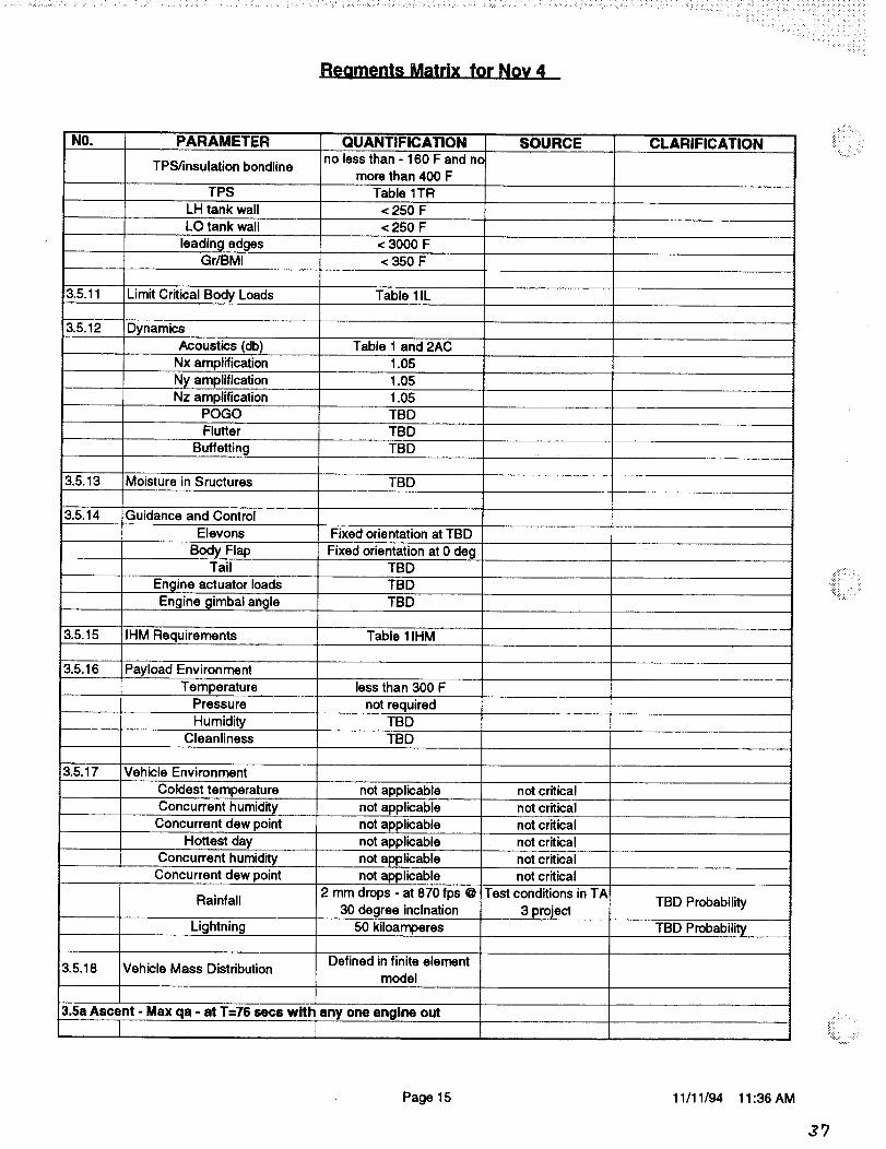
NO. PARAMETER QUANTIFICATION
no less than - 160 F and noTPS/insulation bondline
more than 400 FTPS Table 1TR
LH tank wall < 250 FLO tank wall < 250 F
leading edgesGr/BMI
< 3000 F
<350 F
SOU RCE CLARIFICATION
3.5.11 Limit Critical Body Loads Table 11L
3.5.12 Dynamics
Acoustics (db) Table 1 and 2ACNx amplification 1.05
Ny amplification 1.05
Nz amplification 1.05POGO TBD
Flutter TBD
Buffetting TBD
3.5.13 Moisture in Sructures TBD
3.5.14 iGuidance and Control
Elevons Fixed orientation at TBD
Body Flap Fixed orientation at 0 degTail TBD
Engine actuator loads TBD
Engine gimbal angle TBD
3.5.15 IHM Requirements Table 11HM
3.5.16 Payload Environment
Temperature less than 300 F
Pressure not required
Humidity TBDCleanliness TBD
3.5.17 Vehicle Environment
Coldest temperature not applicable not critical
Concurrent humidity not applicable not critical
Concurrent dew point not applicable not criticalHottest day not applicable not critical
Concurrent humidity not applicable not critical
Concurrent dew point not applicable not critical
Rainfall 2 mm drops - at 870 fps @ Test conditions in TA30 degree inclnation 3 project TBD Probability
Lightning 50 kiloamperes TBD Probability
Defined in finite element3.5.18 Vehicle Mass Distribution
model
3.5a Ascent - Max qa - at T=76 sees with any one engine out
t
:!iii:{:iii!:i_i;:
_iiiiilli'iii_
Page 15 11/11/94 11:36 AM
37
Reoments Matrix for Nov 4
NO,
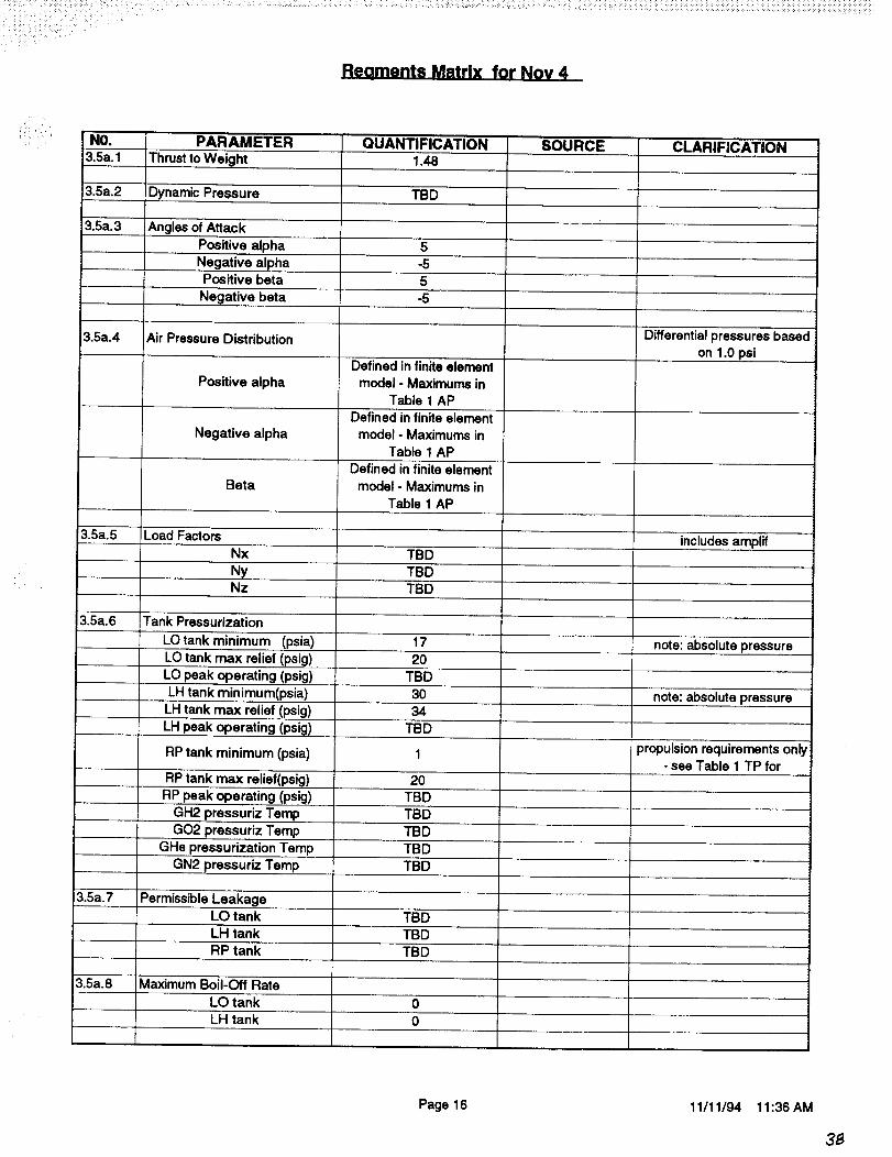
3.5a.1
3.5a.2
3.5a.3
3.5a.4
3.5a.5
3.5a.6
PARAMETER
Thrust to Weight
Dynamic Pressure
Angles of Attack
Positive alpha
Negative alphaPositive beta
Negative beta
Air Pressure Distribution
Positive alpha
Negative alpha
Beta
Load Factors
Nx
NyNz
Tank Pressurization
LOtank minimum (psia)
LO tank max relief (psig)LO peak operating (psig)
QUANTIFICATION1.48
TBD
5
-55
-5
Defined in finite elementmodel - Maximums in
Table 1 AP
Defined in finite element
model- Maximums inTable 1 AP
Defined in finite element
model - Maximums in
Table 1 AP
TBDTBD
TBD
17
20
TBD
LH tank minimum(psia) 30
LH tank max relief (psig) 34
LH peak operating (psig) TBD
RP tank minimum (psia)
RP tank max relief(psig)RP peak operating (psig)
GH2 pressuriz Temp
GO2 pressuriz Temp
GHe pressurization Temp
GN2 pressuriz Temp
20TBD
TBD
TBD
TBDTBD
3.5a.7 Permissible LeakageLO tank TBD
LH tank TBDRP tank
Maximum Boil-Off Rate
LO tank
TBD
3.5a.8
0
LH tank 0
SOURCE CLARIFICATION
Differential pressures based
on 1.0 psi
includes amplif
note: absolute pressure
note: absolute pressure
propulsion requirements only'- see Table 1 TP for
Page 16 11/11/94 11:36 AM
33
Reoments Matrix for Nov 4
NO.
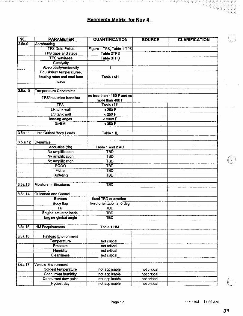
3.5a.9PARAMETER QUANTIFICATION
Aeroheating
TPS Data Points Figure 1 TPS, Table 1 TPS
TPS gaps and steps Table 2TPSTPS waviness Table 3TPS
Catalycity
Absorptivity/emissivity 1Equilibrium temperatures,
heating rates and total heat Table 1AHloads
3.5a.10 Temperature Constraintsno less than - 160 F and n¢
TPS/insulation bondlinemore than 400 F
TPS Table 1TRLH tank wall < 250 F
LO tank wall < 250 F
leading edges < 3000 FGr/BMI < 350 F
3.5a.11 Limit Critical Body Loads Table 1 IL
3.5.a.12 Dynamics
Acoustics (db) Table 1 and 2 AC
Nx amplification TBD
Ny amplification TBD
Nz amplification TBDPOGO TBD
Flutter TBD
Buffeting TBD
3.5a.13 Moisture in Structures TBD
SOURCE
3.5a.14 Guidance and Control
Elevons fixed TBD orientation
Body flap fixed orientation at 0 degTail TBD
Engine actuator loads TBD
Engine gimbal angle TBD
3.5a.15 IHM Requirements Table IlHM
3.5a.16 Payload Environment
Temperature not criticalPressure not critical
Humidity not criticalCleanliness not critical
3.5a.17 Vehicle Environment
Coldest temperature not applicable not criticalConcurrent humidity not applicable not critical
Concurrent dew point not applicable not critical
not applicableHottest day not critical
CLARIFICATION
.,...
_iilii̧̧ /_
Page 17 11/11/94 11:36 AM
3't
'_ii_ _i _ _
i_ i:
NO. PARAMETER QUANTIFICATION SOURCE CLARIFICATION
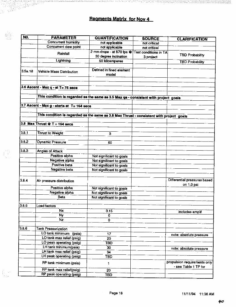
Concurrent humidity not applicable not criticalConcurrent dew point not applicable not critical
Rainfall 2 mm drops - at 870 fps @ iTest conditions in TATBD Probability
.... 30 degree inclnation 3 projectLightning 50 kiloamperes TBD Probability
3.5a. 18 Vehicle Mass Distribution Defined in fined elemenlmodel
3.6 Ascent - Max q - at T= 76
This condition is regarded as the same as 3.5 Max qa - conslatent with project goals
3.7 Ascent - Max g - starts at T= 164 secs
This condition Is regarded as the same as 3.8 Max Thrust - conslatent with project goals
3.8 Max Thrust @ T = 164 sece
3.8.1 Thrust to Weight 3
'3.8.2
3.8.3
Dynamic Pressure
Angles of Attack
Positive alpha
Negative alpha
60
Not significant to goals
Not significant to goalsPositive beta Not significant to goals
Negative beta Not significant to goals
3.8.4 Air pressure distribution
Positive alpha Not significant to goalsNegative alpha Not significant to goals
Beta Not significant to goals
3.8.5 Load factors
Differential pressures based
on 1.0 psi
Nx 3,15 includes amplifNy 0Nz 0
3.8.6 Tank Pressurization
LO tank minimum (psia)
LO tank max relief (psig)
LO peak operating (psig)
LH tank minimum(psia)LH tank max relief (psig)
LH peak operating (psig)
RP tank minimum (psia)
RP tank max relief(psig)
17
20
TBD30
34
TBD
2OTBDRP peak operating (psig)
note: __hsolute pressure
note: absolute pressure
propulsion requirements only- see Table 1 TP for
Page 18 11/11194 11:36 AM

Reoments Matrix for No¥ 4
NO. PARAMETER QUANTIFICATION SOURCE CLARIFICATION
GH2 pressuriz Temp TBD
GO2 pressuriz Temp TBD
GHe pressurization Temp TBD
GN2 pressuriz Temp TBD
3.8.7 Permissible LeakageLO tank TBDLH tank TBD
RP tank TBD
3.8.8 Maximum Boil-Off Rate
LO tank 0
LH tank 0
3.8.9 AeroheatingTPS Data Points Figure 1 TPS, Table 1 TPS
TPS gaps and steps Table 2TPSTPS waviness Table 3TPS
CatalycityAbsorptivity/emissivity 1
Equilibrium temperatures,
heating rates and total heat Table 1AHloads
3.8.10 Temperature Constraints
TPS/insulation bondlineno less than - 160 F or
greater than 400 FTPS Table 1TR
LH tank wall < 250 F
LO tank wall < 250 F
Leading edges < 3000 FGr/BMI < 350 F
3.8.11 Limit Critical Body Loads Table 1 IL
3.8.12 Dynamics
Acoustics (db) Not significant to goalsNx amplification 1.05
Ny amplification 1
Nz amplification 1POGO
Flutter Not applicable
Buffetting Not applicable
3.8.13 Moisture in Structures TBD
3.8.14 Guidance and Control
Elevons TBD
Body flap TBDTail TBD
Engine actuator load TBD
Engine gimbal angle TBD
";:iiii_il i¸ _
Page 19 11/11/94 11:36 AM
=//

Reaments Matrix for Noy 4
NO. PARAME./I::R QUANTIFICATION
3.8.15 IHM Requirements Table IlHM
3.8.16
3.8.17
3.8.18
Payload Environment
TemperaturePressure
HumidityCleanliness
Vehicle Environment
Coldest temperatureConcurrent humidity
Concurrent dew point
not critical
not critical
not criticalnot critical
not applicable
not applicable
not applicable
SOURCE
not criticalnot critical
not criticalHottest day not applicable not critical
Concurrent humidity not applicable not critical
Concurrent dew point not applicable not critical
Rainfall not applicable
Lightning 50 kiloamperes
Vehicle mass distribution Defined in finite elementmodel
Test conditions in TA
3 project
3.8a Ascent - Max Thrust - at T= more than 164 sece -with any one engine out
3.8a. 1 Thrust to Weight 3
3.8a.2 Dynamic Pressure
3.8a.3
3.8a.4
3.8a.5
3.8a.6
60
Angles of Attack
Positive alpha Not significant to goalsNegative alpha
Positive beta
Negative beta
Air pressure distribution
Positive alpha
Negative alphaBeta
Nx
Not significant to goals
Not significant to goals
Not significant to goals
Load factors
Not significant to goals
Not significant to goals
Not significant to goals
NyNz 0
Tank Pressurization
LOtank minimum (psia)LO tank max relief (psig)
LO peak operating (psig)
LH tank minimum(psia)
LH tank max relief Ipsi_ll
CLARIFICATION
TBD Probability
TBD Probability
Differential pressures based
on 1.0 psi
3.15 includes amplif0
172O
TBD
30
34
note: absolute pressure
note: __bsolute pressure
Page 20 11/11194 11:36 AM

Reoments Matrix for Nov 4
...........i:_i_!ii_ii_ii
NO. PARAMETER QUANTIFICATION SOURCE CLARIFICATION
LH peak operating (psig) TBD
RP tank minimum (psia) 1 propulsion requirements only- see Table 1 TP for
RP tank max relief(psig) 20
RP peak operating (psig) TBDGH2 pressuriz Temp TBD
GO2 pressuriz Temp TBD
GHe pressurization Temp TBDGN2 pressuriz Temp TBD
3.8a.7 Permissible LeakageLO tank TBD
LH tank TBD
RP tank TBD
3.8a.8 Maximum Boil-Off Rate
LO tankLH tank
3.8a.9 AeroheatingTPS Data Points
TPS gaps and stepsTPS waviness
00
Not significant to goals
Not significant to goalsNot significant to goals
Catalycity Not significant to goals
Absorptivity/emissivity Not significant to goals
Equilibrium temperatures,
heating rates and total heatloads
3.8a.10 Temperature Constraints
TPS/insulation bondline
TPS
LH tank wall
LO tank wall
Leading edgesGr/BMI
3.8a.11 Limit Internal Body Loads
3.8a.12 Dynamics
Acoustics (db)
Nx amplification
Not significant to goals
Nz amplification
no less than - 160 For
greater than 400 FTable 1TR
< 250 F
< 250 F
< 3000 F
<350 F
Table 1 IL
Not significant to goals1.05
Ny amplification 11
POGO
Flutter
Bufletting
3.8a.13 Moisture in Structures
3,8a.14 Guidance and Control
Not applicableNot applicable
TBD
Page 21 11/11/94 11:36 AM

Reoments Matrix for NOv 4
:: i!_i:NO. PARAMETER
Elevons
Body flapTail
Engine actuator load
Engine gimbal angle
3.8a.15 IHM Requirements
3.8a.16 Payload Environment
TemperaturePressure
Humidity
QUANTIFICATION SOURCETBD
TBD
TBDTBD
TBD
Table 11HM
TBD
TBD
TBDCleanliness TBD
3.8a.17 Vehicle Environment
Coldest temperature not applicable not critical
3.8a. 18
Concurrent humidity
Concurrent dew point
Hottest dayConcurrent humidity
Concurrent dew point
Rainfall
not applicablenot applicable
not applicablenot applicable
not applicable
not applicable
Lightning 50 kiloamperes
Vehicle mass distribution
3.9 Orbit Insertion to De-Orbit
3.9.1 Vehicle Orientation
3.9.2 Docking
Approach velocities
Docking loads
3.9.3 Tank Pressurization
LO tank minimum (psia)LO tank max relief (psig)
LO peak operating (psig)
LH tank minimum(psia)
LH tank max relief (psig)
LH peak operating (psig)RP tank minimum (psia)
RP tank max relief(psig)
RP peak operating (psig)GH2 pressuriz Temp
GO2 pressuriz Temp
...... GHe pressurization Temp
GN2 pressuriz Temp
3.9.4 Permissible LeakacJe
Defined in finite elementmodel
Docked to station
Table 1DO
Table 1DO
16.7
20
Not applicable16.7
34
not criticalnot critical
CLARIFICATION
not criticalnot critical
not criticalTest conditions in TA
TBD Probability3 project
TBD Probability
note: absolute pressure
note: absolute pressure
Not applicable16.7
20
Not applicableTBD
TBD
TBD
TBD
Page 22 11/11/94 11:36 AM

Reaments Matrix for Nov 4
NO. PARAMETER
LO tank
LH tank
QUANTIFICATIONTBD
TBD
RP tank TBD
3.9.5 Temperature Constraints
TPS/insulation bondline
TPSLH tank wall
LO tank wall
Leading edgesGr/BMI
3.9.6 Environment
no less than - 160 F or
greater thna 400 FTable 1TR
< 250 F
< 250 F< 3000 F
< 375 F
NASA TM-4527 June 94Micrometeoroid
SOURCE CLARIFICATION
DebrisUltra violet Radiation
NASA TM-4527 June 94
EUVS = 5 daysVacuum TBD
Atomic oxygen 1 x 10 exp 21 atoms/sq cm
3.9.7 Thermal environment Table 1TH
IHM requirements
Payload Environment
TemperaturePressure
Table 11HM3.9.8
3.9.9
not critical
not critical
Humidity not criticalCleanliness not critical
3.10 Entry Heating
3.10.1 Cross Range
3.10.2 Vehicle L/D
3.10.3 AeroheatingTPS Data Points
TPS gaps and steps
1100 nm
> 1.5 Hypersonic flight >
4 at landing
!Figure 1 TPS, Table 1 TPSTable 2TPS
TPS waviness Table 3TPS
Catalycity
Absorptivity/emissivityEquilibrium temperatures,
heating rates and total heatloads
Table 1AH
3.10.4 Structural Temperatures Table 1TE
3.10.5 Temperature Constraints
TPS/insulation bondlineno less than - 160 F or
greater thna 400 F
Probability TBD
Probability TBD
iiii!i!i,:i_̧ •_!
Page 23 11/11/94 11:36 AM
_/5
i¸¸ /_ !rll¸:_ •
Reoments Matrix for Nov 4
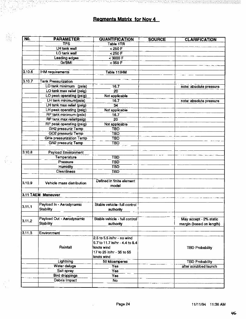
NO. PARAMETER QUANTIFICATION SOURCE CLARIFICATIONTPS Table 1TR
LH tank wall < 250 FLO tank wall < 250 F
Leading edges < 3000 FGr/BMI < 350 F
3.10.6 IHM requirements Table 111HM
3.10.7 Tank Pressurization
LO tank minimum (psia) 16.7
LO tank max relief (psig) 20
LO peak operating (psig) Not applicableLH tank minimum(psia)
note: absolute pressure
16.7 note: absolute pressureLH tank max relief (psig) 34
LH peak operating (psig) Not applicable
RP tank minimum (psia) 16.7
RP tank max relief(psig) 20
RP peak operating (psig) Not applicable
GH2 pressuriz Temp TBDTBD
TBD
TBD
TBD
GO2 pressuriz Temp
GHe pressurization Temp
GN2 pressuriz Temp
3.10.8 Payload Environment
TemperaturePressure TBD
Humidity TBDCleanliness TBD
Defined in finite element_3.10.9 Vehicle mass distribution
model
3.11 TAEM Maneuver
3.11.1 Payload In - Aerodynamic Stable vehicle- full controlStability authority
3.11.2 Payload Out - Aerodynamic Stable vehicle - full control May accept - 2% staticStability authority margin (based on length)
3.11.3 Environment
Rainfall
2.5 to 5.5 in/hr - no wind5.7 to 11.7 in/hr - 4.4 to 8.4
knots wind17 to 25 in/hr - 35 to 55
knots wind
TBD Probability
Lightning 50 kiloamperes TBD ProbabilityWater deluge Yes after scrubbed launch
Salt spray Yes
Bird droppings YesDebris Impact No
Page 24 11/11/94 11:36 AM
Lt_

i i¸ i _:_ .... i .... • i •i ¸¸¸ •
Reaments Matrix for Nov 4
NO.3.11.4
PARAMETER
ILoad Factors
Nx
NyNz
QUANTIFICATION
TBD
Neg 1.0 to 2.5
Defined in finite element
3.11.5 Air Pressure Distribution model - Maximums inTable 1 AP
3.11.6 :Tank Pressurization
LO tank minimum (psia)
LO tank max relief (psig)
3.11.9
16.720
LO peak operating (psig) Not applicable
LH tank minimum(psia) 16.7LH tank max relief (psig) 34
LH peak operating (psig) Not applicable
RP tank minimum (psia) 16.7
RP tank max relief(psig) 20RP peak operating (psig) Not applicable
GH2 pressuriz Temp TBDGO2 pressuriz Temp TBD
GHe pressurization Temp TBD
GN2 pressuriz Temp TBD
Limit Intemal Body Loads
3.11.7 Temperature ConstraintsTPS/insulation bondline no less than - 160 F
TPS Table 1TR
LH tank wall < 250 FLO tank wall < 250 F
leading edges < 3000 FGr/BMI < 350 F
3.11.8 Structural Temperatures Table 2TE
Table 1 IL
Dynamics
Nx amplification
Ny amplificationNz amplification
3.11.10
3.11.11
Flutter
Buffetting
Moisture in Structures
TBDTBDTBD
TBD
TBD
TBD
3.11.12 Guidance and Control
Elevons Deflection limits - TBD
Body Flaps Deflection limits - TBDTail Deflection limits - TBD
Engine actuators Not required
Maximum roll angle 60 deg MIL SPECMaximum roll rate 20 deg/sec
SOURCE CLARIFICATION
includes amplif
MIL SPEC
Differential pressures based
on neg1.0 psi
note: absolute pressure
note: absolute pressure
Page 25 11/11/94 11:36 AM

,i_' i_
il ii,!_ NO. PARAMEIER
3.11.13 IHM requirements
3.11.14 Payload Environment
TemperaturePressure
HumidityCleanliness
3.11.15 Vehicle Mass Distribution
3.12 Malt
3.12.1
3.12.2
QUANTIFICATION
Table IHM 1
less than 300 F
not critical
not critical
not critical
Defined infinite element
Gear Landing - Spin Up - Both wheels concurrent
On Concrete Surface with
Propellant Residuals
Sink Speed-Max Weight 10 ft/sec
Sink speed intact abort 6 ft/sec
Maximum touchdown speed 190 knotsMinimum touchdown speed 170 knots
Max cross wind 20 knots
Main Gear stroke TBD
Main Gear Max Z load TBD
Side gear load TBDCrosswind 15 knots
3.12.3
3.12.4
Lightning
Load Factors
Rotational accel abt yNy
50 kiloamperes
TBD0
Nx TBDNz TBD
Tank Pressurization
LOtank minimum (psia) 16.7
LO tank max relief (psig) 20
LO peak operating (psig) Not applicableLH tank minimum(psia) 16.7
LH tank max relief (psig) 34
LH peak operating (psig) Not applicableRP tank minimum (psia) 16.7
RP tank max reliaf(psig)
3.12.5
RP peak operating (psig)
20
Not applicableGH2 pressuriz Temp TBD
GO2 prassuriz Tamp TBD
GHe pressurization Temp TBDGN2 pressuriz Temp TBD
Temperature ConstraintsTPS/insulation bondline
TPS
LH tank wall
no less than - 160 FTable 1TR
< 250 F
SOURCE CLARIFICATION
MIIJSPEC
MIL SPEC
MIL SPEC
Shuttle Tire capability on landing
TBD Probability
note: absolute pressure
note: absolute pressure
Page 26 11/11/94 11:36 AM
Reaments Matrix for Nov 4
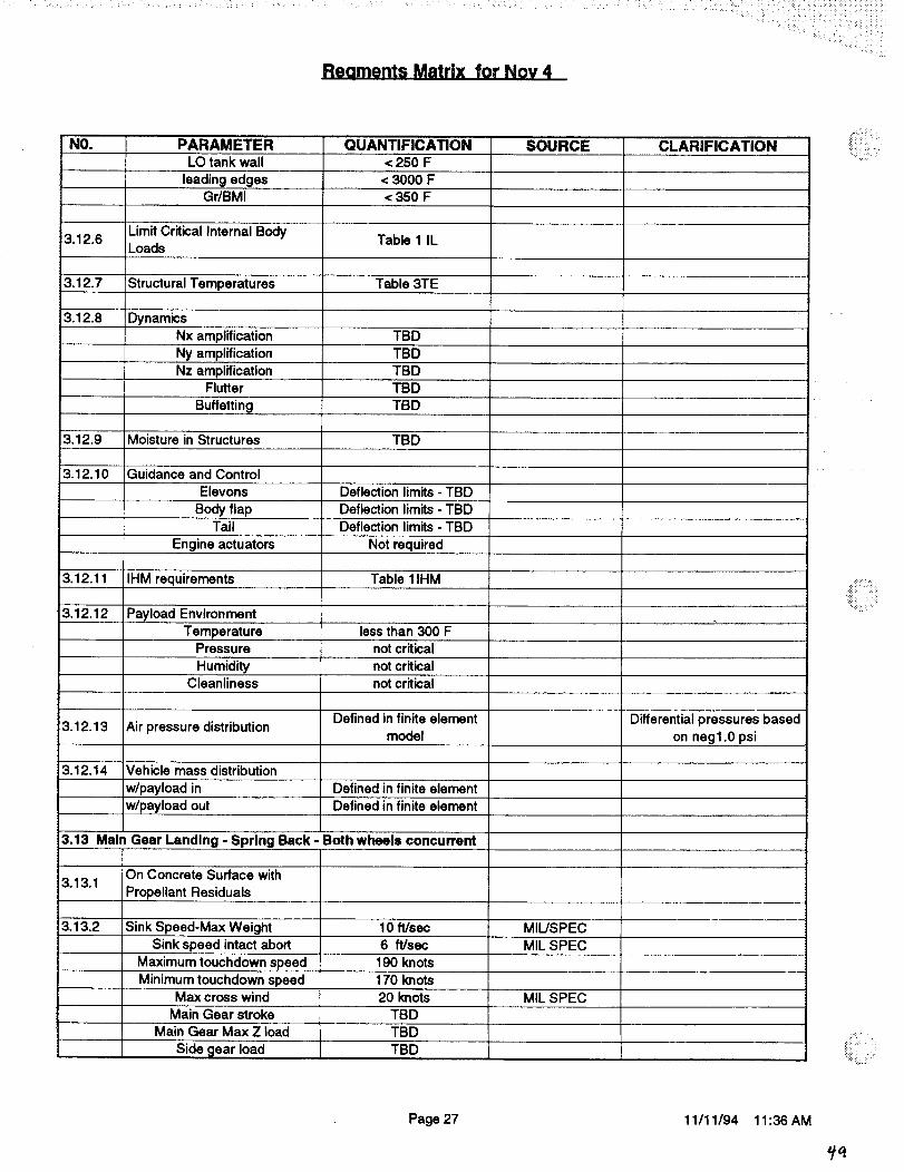
NO. PARAMETER QUANTIFICATION SOURCE CLARIFICATIONLO tank wall < 250 F
leading edges < 3000 FGr/BMI < 350 F
3.12.6 Limit Critical Internal Body Table 1 ILLoads
3.12.7 Structural Temperatures Table 3TE
3.12.8 Dynamics
Nx amplification TBDTBDNy amplification
Nz amplification TBDFlutter TBD
Bufletting TBD
3.12.9 Moisture in Structures TBD
3.12.10 Guidance and Control
Elevons Deflection limits - TBD
Body flap Deflection limits - TBDTail Deflection limits - TBD
Engine actuators Not required
3.12.11 IHM requirements Table 11HM
3.12.12 Payload EnvironmentTemperature tessthan 300 F
Pressure not critical
Humidity not criticalCleanliness not critical
Defined in finite element3.12.13 Air pressure distribution
model
3.12.14 Vehicle mass distribution
w/payload in Defined in finite element
w/payload out Defined in finite element
3.13 Main Gear Landing - Spring Back- Both wheels concurrent
On Concrete Surface with3.13.1
Propellant Residuals
3.13.2 Sink Speed-Max Weight 10 ft/sec MIL/SPEC
Sink speed intact abort 6 ft/sec MIL SPEC
Maximum touchdown speed 190 knots
Minimum touchdown speed 170 knotsMax cross wind 20 knots MIL SPEC
Main Gear stroke TBD
Main Gear Max Z load TBD
TBDSide _lear load
Differential pressures based
on nag1.0 psi
::::::: : ::
iiii_' i
Page 27 11/11/94 11:36 AM
,/9

: C_I ii _!i ¸ ii _
Reoments Matrix for Nov 4
il:_ • i •
NO.
3.13.3
3.13.4
3.13.5
3.13.6
PARAMETERCrosswind
Lightning
Load Factors
Rotational accel abt y
NyNx
Nz
Tank Pressurization
LO tank minimum (psia)
LO tank max relief (psig)LO peak operating (psig)
LH tank minimum(psia)
LH tank max relief (psig)
LH peak operating (psig)
RP peak operating (psig)GH2 pressuriz Temp
QUANTIFICATION
15 knots
50 kiloamperes
TBD
0TBD
TBD
16.720
Not applicable16.734
Not applicableRP tank minimum (psia) 16.7
RP tank max relief(psig) 20
Not applicable
GO2 pressuriz Temp
GHe pressurization Temp
GN2 pressuriz Temp
Temperature ConstraintsTPS/insulation bondline
TPS
LH tank wall
LO tank wall
leading edgesGr/BMI
Limit Internal Body Loads
3.13.7 Structural Temperatures
3.13.8 Dynamics
Nx amplificationNy amplification
TBD
TBD
TBDTBD
no less than - 160 F
Table 1TR
< 250 F
< 250 F< 3000 F
<350 F
Table 1 IL
Table 3TE
TBD0
Nz amplification TBDFlutter TBD
Buffetting TBD
Moisture in Structures
Guidance and Control
Elevons
Body FlapsTail
Engine actuators
3.13.11 IHM requirements
TBD
Deflection limits - TBDDeflection limits - TBD
Deflection limits - TBD
not required
Table 11HM
SOURCEShuttle
CLARIFICATION
Tire capability on landingTBD Probability
note: absolute pressure
note: absolute pressure
Page 28 11/11/94 11:36 AM
So

Reaments Matrix for Nov 4
NO. PARAMETER QUANTIFICATION SOURCE CLARIFICATION
3,13.12 Payload EnvironmentTemperature less than 300 F
Pressure not critical
Humidity not critical
Cleanliness not critical
3.13.13 Vehicle Mass Distribution
W/payload in Defined in finite element
W/payload out Defined in finite element
3.14 Nose Gear Slapdown Landing
On Concrete Surface with3.14.1
Propellant Residuals
3.14,2 Minimum Speed for Pitchover TBD
Maximum pitchover rate TBD
Maximum speed for pitchover. TBD
Nose attitude at slapdown TBDFwd Gear stroke TBD
Fwd Gear Max Z load TBD
Fwd Side gear load TBD
Lightning 50 kiloamperes
3.14.3 Load Factors
Ny 0Nx TBD
Nz TBD
3.14.4 Tank Pressurization
LOtank minimum (psia) 16.7
LO tank max relief (psig) 20
LO peak operating (psig) Not applicableLH tank minimum(psia) 16.7
LH tank max relief (psig) 34
LH peak operating (psig)
RP tank max relief(psig)
Not applicable
RP tank minimum (psia) 16.720
RP peak operating (psig) Not applicable
GH2 pressuriz Temp TBD
GO2 pressuriz Temp TBD
GHe pressurization Temp TBDGN2 pressuriz Temp TBD
3.14.5 Temperature ConstraintsTPS/insulation bondline no less than - 160 F
TPS Table 1TR
LH tank wall < 250 FLO tank wall < 250 F
leading edges < 3000 F
TBD Probability
note: absolute pressure
note: absolute pressure
:i!ii!ii:!;!!!:
.,!_!:!:!,iL:_.
Page 29 11/11/94 1i:36 AM
_'/

Reoments Matrix for Nov 4
NO. PARAMETER QUANTIFICATIONGr/BMI < 350 F
3.14.6 Limit Intemal Body Loads
3.14.7 Structural Temperatures
3.14.8 Dynamics
Nx amplificationNy amplification
Nz amplificationFlutter
Table 1 IL
Table 3TE
TBD
TBD
TBD
Bufletting TBD
3.14.9 Moisture in Structures TBD
3.14.10 Guidance and Control
Elevons
Body FlapsTail
Engine actuators
IHM Requirements
Payload Environment
3.14.11
3.14.12
TemperaturePressure
HumidityCleanliness
3.14.13 Vehicle Mass Distribution
W/payload in
W/payload out
3.15 Return to OPF and In OPF
3.15.1 Towing Load FactorsNz
Nx
Ny
3.15.2 Taxi Load Factors
NzNx
Ny
3.15.3 Jacking/HoistingNz
Nx
Ny
3.15.4
Deflection limits - TBDDeflection limits - TBD
Deflection limits - TBD
not required
Table 11HM
less than 300 F
not critical
not criticalnot critical
Defined in finite elementDefined in finite element
*not critical
*not critical
*not critical
2.0
*not critical
*not critical
*not critical
SOURCE CLARIFICATION
* except for local fitting
* except for local fitting* except for local fitting
* except for local fitting
* except for local fitting
* except for local fitting
*not critical * except for local fitting*not critical * except for local fitting
LO, LH, and RP tank pressures 2.0 minumum
Page 30 11/11/94 11:36AM
,53-,

Reoments Matrix for Nov 4
NO. PARAMETER QUANTIFICATION
3,15.5 II-IM Requirements
3.15.6 Payload Environment
TemperaturePressure
Humidity
not required
not required
not requiredCleanliness not required
3.15.7 Vehicle Sating
Purge TBD
Unload payload TBD
3.15.8 Vehicle Mass Distribution
W/payload in Defined in finite element
W/payload out
3.15.9 WaterproofingTABI
CFBIAETB
Others
3.15.10 Install Payload
3.1.5.11 Payloads Processed in Parallel,Off-Line
3.16 Loading Spectrums
Defined in finite element
TBD
TBDTBD
TBD
SOURCE CLARIFICATION
proof test - one cycle 300
missions -1 added cycle3.16.1 LO Tank Pressuresevery 10th flight- see Table
3.16.1
proof test - one cycle 300
missions -1 added cycle3.16.2 LH Tank Pressuresevery 10th flight- see Table
3.16.1
3.16.3 Fuselage Body Loads Table LS-1
3.16.4 Wing Loads Table LS-2
3.16.5 Tail Loads Table LS-3
3.16.6 Thrust Structure Table LS-4
See criteria document for safety factors, damage tolerance, etc.
"::iiiii!_.!_
Page 31 11/11/94 11:36 AM
_3

ii::i • _ _
TABLE 2 GW
DESIGN PEAK WIND SPEED PROFILE FOR A 1% RISK OF
EXCEEDING THE 18.3 METER REFERENCE LEVEL PEAK WIND
SPEED FOR THE WINDIEST TWO-WEEK EXPOSURE PERIOD
HEIGHT PEAK WIND SPEED
KSC VAFB
(m) (ft) (m/sec) (knots) (m/sec) (knots)
18.3 60 31.1 60.4 25.0 48.6
30.5 100 33.1 64.3 26.9 52.3
61.0 200 36.0 69.9 29.7 57.7
91.4 300 37.8 73.5 31.5 61.2
121.9 400 39.1 76.0 32.8 63.8
152.4 500 40.2 78.1 33.9 65.9
TEN-MINUTE STEADY STATE WIND SPEED PROFILE ASSOCIATED
WITH 1% RISK PEAK WiND SPEED PROFILE FOR THE WINDIEST
TWO-WEEK EXPOSURE PERIOD
HEIGHT MEAN WIND SPEED
KSC VAFB
(m) (ft) (m/sec) (knots) (m/sec) (knots)
18.3 60 20.6 40.1 19.1 37.1
30.5 100 23.0 44.7 21.3 41.3
61.0 200 26.5 51.4 24.6 47.7
91.4 300 28.6 55.6 26.6 51.6
121.9 400 30.2 58.6 28.1 54.5
152.4 500 31.4 61.1 29.3 56.8
Vo!,:me X - Book 2 10.10-13Revision L
CHANGE NO. 191
-_"t
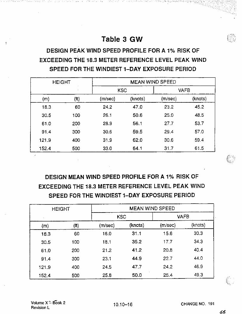
Table 3 GW
DESIGNPEAKWINDSPEEDPROFILEFORA 1% RISKOF
EXCEEDINGTHE18.3METERREFERENCELEVELPEAKWINDSPEEDFORTHEWINDIEST1-DAY EXPOSUREPERIOD
,iiiiii_3!iii{i
HEIGHT MEAN WIND SPEED
KSC VAFB
(m) (ft) (m/sec) (knots) (m/sec) (knots)
18.3 60 24.2 47.0 23.2 45.2
30.5 100 26.1 50.6 25.0 48.5
61.0 200 28.9 56.1 27.7 53.7
91.4 300 30.6 59.5 29.4 57.0
121.9 400 31.9 62.0 30.6 59.4
152.4 500 33.0 64.1 31.7 61.5
DESIGN MEAN WIND SPEED PROFILE FOR A 1% RISK OF
EXCEEDING THE 18.3 METER REFERENCE LEVEL PEAK WIND
SPEED FOR THE WINDIEST 1-DAY EXPOSURE PERIOD
HEIGHT MEAN WIND SPEED
KSC VAFB
(m) (ft) (m/sec) (knots) (m/sec) (knots)
18.3 60 16.0 31.1 15.6 30.3
30.5 100 18.1 35.2 17.7 34.3
61.0 200 21.2 41.2 20.8 40.4
91.4 300 23.1 44.9 22.7 44.0
21.9 400 24.5 47.7 24.2 46.9
52.4 500 25.8 50.0 25.4 49.3
Volume X: B_ok 2Revision L
10.10-16 CHANGE NO. 191
,&6

(a)
Table 4 GW
DESIGN LAUNCH PEAK WIND SPEED PROFILES FOR THE
18.3 METER REFERENCE LEVEL PEAK WIND SPEED
FOR THE WINDIEST 1-HOUR EXPOSURE PERIOD
All Azimuths Considered (For a 5% risk of exceeding)
HEIGHT PEAK WIND SPEED
KSC VAFB
(ft) (m/s) (k) (m/s) (k)(m)
10 33 15.8 30.8 15.8 30.8
18.3 60 17.7 34.4 17.7 34.4
30.5 100 19.5 37.9 19.5 37.9
61.0 200 22.1 43.0 22.1 43.0
91.4 300 23.9 46.4 23.9 46.4
121.9 400 25.2 48.9 25.2 48.9
152.4 500 26.2 51.0 26.2 51.0
(b) Limited Azimuth Considered (For wind from South [180 °] at KSC and for 60 °,arc
centered on West and East at VAFB)
HEIGHT PEAK WIND SPEEDKSC VAFB
FROM DUE SOUTH WEST EAST
(m) (ft) (m/s) (k) (m/s) (k) (m/s) (k)
!i:_: ili: ¸'iii! :i_i_i _
10 33 10.7 20.7 10.7 20.7 12.6 24.6
18.3 60 12.3 24.0 12.3 24.0 14.4 28.0
30.5 100 14.0 27.2 14.0 27.2 16.0 31.3
61.0 200 16.5 32.1 16.5 32.1 18.7 36.3
91.4 300 18.2 35.4 18.2 35.4 20.4 39.6
121.9 400 19.6 38.0 19.6 38.0 21.7 42.2
152.4 500 20.7 40.1 20.7 40.1 22.8 44.3
NOTE:For KSC wind directions, (_ between 134 ° and 226 ° compute the peak wind
12.3 m/s
speed atthe 18.3 m level by: U1B-3 = - COS e andthen use Equation 1,
Section 4.1.2.1.1 to obtain peak wind versus height. For all other wind direc-
tions use Table 4.2. l(a).
Volume X_- Book 2Revision L 10.10--27 CHANGE NO. 193
,5(,,

Table 1 TP - Design Tank Pressures
Mission Phase
Prelaunch unfueled
LH fueling
End LH pressurizationLO fueling_
End LO pressurizationLiftoff
LO tank
operating
3.0
3.0
Configuration 2A Limit Tank Pressures
_r_
LH Tank _ __ LO tank
f3- o L
minimum
0.0
0.0
20 to 0
20 to 0
20 to 0
30.0
30.0
16.7
16.7
2.0
2.0
3.0
3.0
18.0
18.0
LO tankmaximum
20.0
20.0
20.0
20.0
20.0
20.0
MECO 18.0 20.0
On orbit 18.0 20.0
Start of Entry_TAEM maneuvers
18.0 20.0
5.33.3
Landing 3.3 5.3
Phases 3 to trade off anal 'sis
5 pressu_ort
Configuration 4 Limit Tank Pressures
LHTank _ __ LOtankminimum _ _--[m--_im-um
LO tank
operating
Mission Phase LO tank
maximum
Prelaunch unfueled 0.0 3.0 5.3 0.0 3.0 20.0
LO fueling 0.0 3.0 5.3 0.0 3.0 20.0
End LO pressurization 0.0 3.3 5.3 16.7 18.0 20.0LH fueling 0.0 3.3 5.3 16.7 18.0 20.0
End LH pressurization 30.0 31.3 34.0 16.7 18.0 20.0Liftoff 30.0 31.3 34.0 16.7 18.0 20.0
MECO 30.0 31.3 34.0 16.7 18.0 20.0
On orbit 16.7 18.0 20.0 16.7 18.0 20.0
Start of Entry_TAEM maneuvers
16.7
2.0
18.0
3.3
20.0 16.7 18.0
3.3
20.0
5.3
2.0 3.3 5.3 2.0 3.3 5.3
10/2_/94
iil_ _ :i_
_iii_i_!__i__,
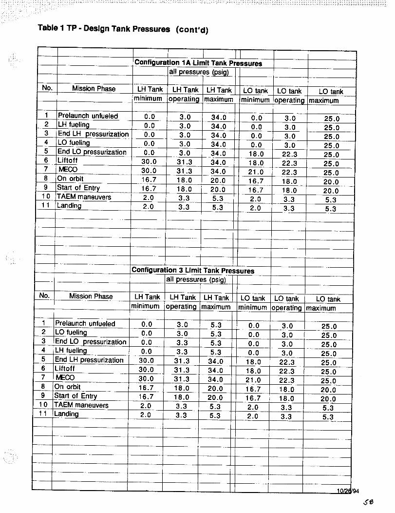
Configuration 1A Limit Tank Pressures
all pressures (psig)
No. Mission Phase LH Tank LH Tank LH Tank LO tank LO tank LO tank
minimum operating maximum ,minimum operating maximum
1 Prelaunch unfueled 0.0 3.0 34.0 0.0 3.0 25.02 LH fueling 0.0
3 End LH pressurization 0.04 LO fueling
5 End LO pressurization6 Liftoff
3.0 34.0 0.0 3.0 25.0
3.0 34.0 0.0 3.0 25.00.0 3.0 34.0 0.0 3.0 25.0
0.0 3.0 34.0 18.0 22.3 25.0
30.0 31.3 34.0 18.0 22.3 25.07 MECO 30.0
8 On orbit 16.7
9 'Start of Entry 16.710 TAEM maneuvers 2.0
1 1 Landing 2.0
31.3 34.0 21.0 22.3 25,018.0 20.0 16.7 18.0 20.0
18.0 20.0 16.7 18.0 20.0
3.3 5.3 2.0 3.3 5.3
3.3 5.3 2.0 3.3 5.3
, :ii!!i?
NO.
Configuration 3 Limit Tank Pressures
all pressures (psig)
Mission Phase LH Tank LH Tank LH Tank
minimum operating maximum
1 Prelaunch unfueled
2 LO fueling
LO tank LO tank LO tank
minimum operating maximum
End LO pressurization
LH fueling
End LH pressurization=Liftoff
0.0 3.0 5.3 0.0 3.0
0.0 3.0 5.3 0.0 3.0
0.0 3.3 5.3 0.0 3.03
4
5
6
7
8
9
10
11
0.0 3.3
31.35.3
34.030.0
25.0
25.0
25.00.0 3.0 25.0
18.0 22.3 25.030.0 31.3 34.0 18.0
MECO 30.0 31.3 34.0 21.0
On orbit 16.7 18.0 20.0 16.7
Start of Entry 16.7TAEM maneuvers 2.0
20.05.3
5.3
18.0
3.3
3.3
22.3
22.3
18.0
25.0
25.0
20.0
Landing 2.0
16.7 18.0 20.0
2.0 3.3 5.3
2.0 3.3 5.3
1 _/_
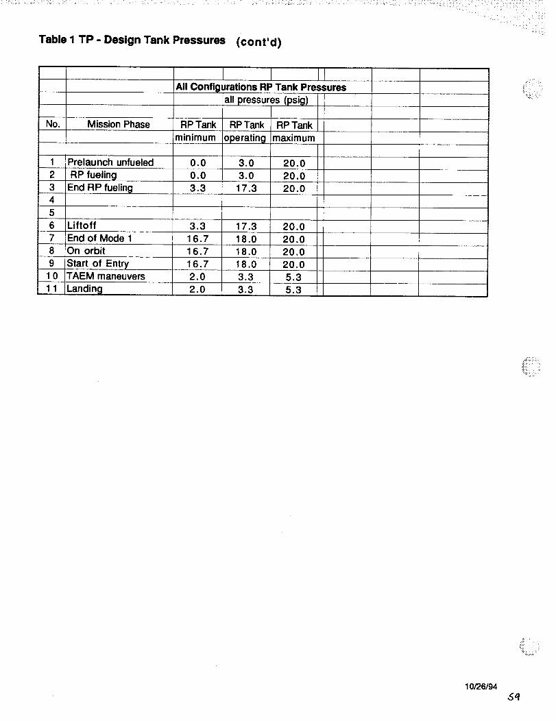
Table I TP - Design Tank Pressures (cont'd)
No. Mission Phase
1 Prelaunch unfueled
2 RP fuelin(
3 End RPfueling4
5
6 Liftoff
7 End of Mode 18 On orbit
9 Start of Entry1 0 TAEM maneuvers
11
I I IrAll Configurations RP Tank Pressures
all pressures (psig)
RPTank RPTank RPTank Iminimum operating maximum
0.0 3.0 20.0
0.0 3.0 20.0
3.3 17.3 20.0
3.3 17.3 20.0
16.7 18.0 20.0
16.7 18.0 20.0
16.7 18.0 20.02.O 3.3 5.3
2.O 3.3 5.3
.:.,:,
"_:i:: _:i ¸_
10/26194_q