requirements and concepts for arctic evacuation
TRANSCRIPT
I
MASTER THESIS
Requirements and concepts for arctic evacuation
Kristian Nedrevåg
Delivered:
14.06.2011
This thesis deals with the subject of evacuation in the Arctic, and design of evacuation systems for this area. One of the challenges of the northward expansion of the oil and gas industry is the performance of evacuation material under arctic conditions. The objective of this thesis is to describe the conditions in the Arctic with emphasis on lifeboat performance, to analyze the hazards and issues of using existing lifeboat systems in the Arctic and to suggest new concepts for arctic evacuation.

II
MASTER THESIS (MASTEROPPGAVE)
FOR
KRISTIAN NEDREVÅG
Spring 2011
REQUIREMENTS AND CONCEPTS FOR ARCTIC EVACUATION
(KRAV OG KONSEPTER FOR EVAKUERING I ARKTISKE STRØK)
Background The global demand for oil is increasing, while large and relatively accessible oil and gas fields are
becoming depleted. Exploration and production of oil and gas resources are therefore moving to new
locations. Amongst other areas, petroleum companies are eager to explore and exploit resources in
the Arctic areas, which have been estimated to hold 25 percent of the global oil and gas reserves.
Operation of manned oil and gas installations in arctic locations is complicated and presents new
challenges. One of the challenges is to maintain the safety of the crew, by obtaining adequate
lifeboat systems for crew evacuation. The master thesis should focus on different methods for
meeting this challenge.
Objectives 1. To compose a specification of requirements for lifeboat systems operating in arctic areas.
2. To analyze existing lifeboat systems and suggest improvements for use in an arctic
environment.
3. To come up with new concepts for evacuation in an arctic environment.
Accomplishments The report should include:
1. A description of the environment in the Arctic with regards to lifeboat operation, with focus
on the Barents Sea.
2. A specification of requirements for lifeboats in arctic operation, with regards to both
regulations and environmental factors.
3. An evaluation of existing conventional and free-fall life boat systems with regards to the
requirements in point two.
4. A description of possibilities for modification of existing lifeboat systems to fulfill the
requirements in point two.

III
5. Basic proposals for new concepts for arctic evacuation, based on the requirements in point
two.
6. A more detailed study of the most promising of the new concepts.
7. A discussion and conclusion on the different concepts.
The work should be carried out in accordance with the rules that apply for Master Thesis
(masteroppgave) at NTNU – Department of Marine Technology
Trondheim, date, year
Stein Ove Erikstad
Professor Supervisor
Date received: 17 January 2011
Date of delivery: 14 June 2011

IV
Preface This master thesis is written by Kristian Nedrevåg in the 10th and final semester at The Norwegian
University of Science and Technology, Faculty of Engineering Science and Technology, Department of
Marine Technology. The work with the thesis counts for 30 credits and has been performed as a
stand-alone project which is not related to my project thesis from the 9th semester.
The subject of the thesis is requirements and concepts for arctic evacuation. Working with this topic
has been very interesting, and has given me the opportunity to gain knowledge in a wide variety of
fields. I have also found it motivating that the increased activity in the far North has been on the
public agenda during the project period.
During the work with the thesis, I have found it necessary to alter the order of the work compared to
the assignment text, as I have concluded that the specification of requirements should be based on
the evaluation of existing lifeboat systems rather than the other way around. I have also found it
suitable to divide the evaluation of existing systems into two different categories; evacuation
material currently in use and existing concepts for arctic evacuation.
I would like to thank Stein Ove Erikstad, who has been my supervising professor for the thesis. I
would also like to thank Arild Lokøy at Umoe Schat-Harding and Sigurd R Jacobsen at Petroleum
Safety Norway, who have given me interesting input during the project.
Finally, I would like to thank my fellow students at office A2.027 for interesting and motivating
discussions on the thesis subject.
Trondheim, 14 June, 2011
Kristian Nedrevåg

V
Table of contents Preface .................................................................................................................................................... IV
Table of contents ..................................................................................................................................... V
List of figures ......................................................................................................................................... VII
List of tables ......................................................................................................................................... VIII
List of appendices ................................................................................................................................... IX
Summary ................................................................................................................................................. X
Conclusion .............................................................................................................................................. XI
Introduction ........................................................................................................................................... XII
1 Background: The history of the modern lifeboat ............................................................................ 1
2 Evacuation ....................................................................................................................................... 3
3 Lifeboats .......................................................................................................................................... 5
3.1 Open lifeboats ......................................................................................................................... 5
3.2 Partially enclosed lifeboats...................................................................................................... 5
3.3 Totally enclosed lifeboats ........................................................................................................ 5
3.4 Free fall lifeboats ..................................................................................................................... 6
3.5 MOB-boats .............................................................................................................................. 7
3.6 Life rafts ................................................................................................................................... 7
3.7 Marine evacuation systems ..................................................................................................... 7
4 The Arctic ......................................................................................................................................... 8
4.1 Definition ................................................................................................................................. 8
4.2 Weather and geographical conditions .................................................................................... 9
5 Evacuation material currently in use ............................................................................................. 16
5.1 Conventional lifeboats........................................................................................................... 16
5.2 Free fall lifeboats ................................................................................................................... 16
6 Hazard identification analysis ........................................................................................................ 18
6.1 Hazard identification analysis ................................................................................................ 18
6.2 What-if analysis ..................................................................................................................... 21
6.3 Conclusions of the analyses................................................................................................... 26
7 Specification .................................................................................................................................. 27
7.1 Existing regulations ............................................................................................................... 27
7.2 Norwegian regulations .......................................................................................................... 28
7.3 Suggestion for basic requirements ........................................................................................ 29
8 Existing arctic evacuation concepts............................................................................................... 32
8.1 Arktos .................................................................................................................................... 32
8.2 AMV Lifeboat ......................................................................................................................... 33
8.3 Seascape ................................................................................................................................ 34
8.4 Polar Haven ........................................................................................................................... 34
8.5 Subevak ................................................................................................................................. 34
9 Evaluation ...................................................................................................................................... 36
9.1 Method .................................................................................................................................. 36
9.2 Arktos .................................................................................................................................... 37
9.3 AMV Lifeboat ......................................................................................................................... 38
9.4 Seascape ................................................................................................................................ 38
9.5 Polar Haven ........................................................................................................................... 39

VI
9.6 Subevak ................................................................................................................................. 39
9.7 Conclusion of the evaluation ................................................................................................. 39
10 Modifications ............................................................................................................................. 40
10.1 Temperature of moving components ................................................................................... 40
10.2 Secondary launching method ................................................................................................ 41
10.3 Alternative evacuation method............................................................................................. 41
10.4 Engine power ......................................................................................................................... 42
10.5 Hull shape .............................................................................................................................. 42
10.6 Hull structure strengthening ................................................................................................. 42
10.7 Propulsion equipment ........................................................................................................... 42
10.8 Sea spray icing ....................................................................................................................... 42
11 Suggested new concepts ........................................................................................................... 43
11.1 Concept 1: The Arctic Free Fall Lifeboat ................................................................................ 43
11.2 Concept 2: The arctic conventional lifeboat ......................................................................... 44
11.3 Concept 3: The arctic survival vehicle ................................................................................... 45
12 The Arctic FFL, concept description........................................................................................... 47
12.1 Goal and focus, general description ...................................................................................... 47
12.2 Main dimensions and capacities ........................................................................................... 47
12.3 Hull design ............................................................................................................................. 48
12.4 Storage .................................................................................................................................. 49
12.5 Launching .............................................................................................................................. 49
12.6 Weight estimation ................................................................................................................. 50
12.7 Operation in ice ..................................................................................................................... 53
12.8 Engine power ......................................................................................................................... 57
12.9 Conning position:................................................................................................................... 57
12.10 Prevention of sea spray icing ............................................................................................ 58
12.11 Propulsion equipment ...................................................................................................... 61
12.12 Concluding comments on the concept ............................................................................. 61
13 Conclusion ................................................................................................................................. 62
14 References ................................................................................................................................. 63
Appendix A ............................................................................................................................................ 64
Appendix B ............................................................................................................................................ 65
Appendix C............................................................................................................................................. 66

VII
List of figures Figure 1: Oil rig surrounded by ice. Picture: oilrig-photos.com ............................................................ XII
Figure 2: "Storm King" arrives in Adelaide, Australia. Picture: Wikimedia commons ............................ 1
Figure 3: The Life-Saving Globe. Picture: Follo Museum ......................................................................... 1
Figure 4: Escape, evacuation and rescue process ................................................................................... 3
Figure 5: Flowchart; Escape, evacuation and rescue .............................................................................. 4
Figure 6: Partially enclosed lifeboat. Picture: Umoe Schat-Harding ....................................................... 5
Figure 7: Conventional lifeboat stored in davit. Picture: Jannicke Nilsen, Teknisk Ukeblad .................. 6
Figure 8: Free fall lifeboats on oil rig. Picture: Victor Gibson, shipsandoil.com ...................................... 6
Figure 9: MOB boat. Picture: Wikimedia commons ................................................................................ 7
Figure 10: Conventional life raft. Picture: Wikimedia commons ............................................................ 7
Figure 11: The Arctic, as defined by the Arctic Circle. Picture: Google Earth ......................................... 8
Figure 12: Satellite photo of a polar low. Image: Wikimedia commons ............................................... 10
Figure 13: The minimum arctic ice cover for certain years. Picture: Wikimedia commons ................. 12
Figure 14: Variations in extent of the arctic ice cover. Picture: Wikimedia commons ......................... 12
Figure 15: Ice cover assessment scale. Figure: Environment Canada ................................................... 13
Figure 16: Range of Sikorsky S-92. Picture generated in Google Earth ................................................. 14
Figure 17: Example of modern stand-by vessel, Stril Herkules. Picture: Skipsrevyen .......................... 15
Figure 18: Full scale free fall lifeboat trial. Photo: Kristian Nedrevåg ................................................... 17
Figure 19: Sunkar Station, equipped with Arktos. Picture: offshore-technology.com ......................... 32
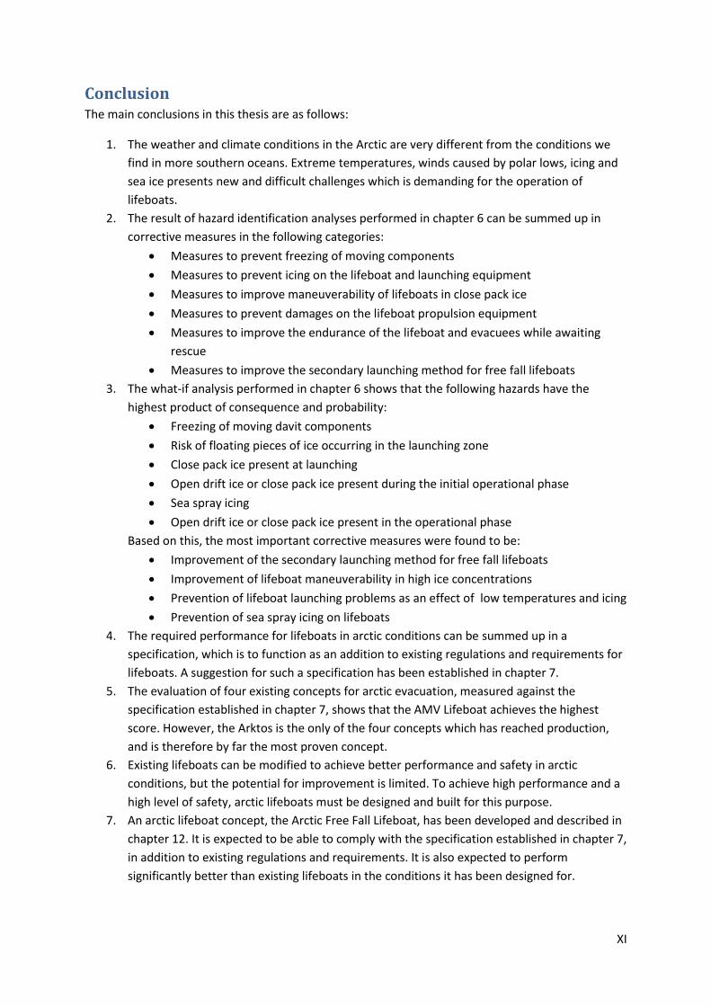
Figure 20: Arktos craft. Picture: Arktos Craft ........................................................................................ 33
Figure 21: Scale model of AMV lifeboat. Picture: Team Innovation Trondheim AS ............................. 33
Figure 22: Seascape lifeboat and launching system. Picture: Seascape 2000 ...................................... 34
Figure 23: Polar Haven. Picture: Mad Rock Marine Solutions .............................................................. 34
Figure 24: The Subevak system. Picture: [1] ......................................................................................... 35
Figure 25: The Arctic FFL. Illustration generated in DELFTship. ............................................................ 48
Figure 26: Bodyplan view from DELFTship ............................................................................................ 54
Figure 27: The Arctic FFL seen from below ........................................................................................... 56
Figure 28: Illustration of counter-rotating Archimedes screws. Illustration generated in Autodesk
Inventor ................................................................................................................................................. 56
Figure 29: Illustration, conning position located in the aft, with view angle indicated ........................ 58
Figure 30: Illustration, conning position located in an extreme forward position, with view angle
indicated ................................................................................................................................................ 58
Figure 31: Layer of ice on an inclining plane ......................................................................................... 59
Figure 32: Required sloping angle as a function of the COF ................................................................. 60

VIII
List of tables Table 1: Summary of trigging events and suggested corrective measures ........................................... 20
Table 2: Extract from summary of trigging events and suggested corrective measures ...................... 21
Table 3: Hazard identification for conventional lifeboats in arctic conditions ..................................... 24
Table 4: Hazard identification for free fall lifeboats in arctic conditions .............................................. 25
Table 5: Summary of evaluation, Arktos ............................................................................................... 37
Table 6: Summary of evaluation, AMV Lifeboat .................................................................................... 38
Table 7: Summary of evaluation: Seascape ........................................................................................... 38
Table 8: Summary of evaluation, Polar Haven ...................................................................................... 39
Table 9: Propulsion methods for use on ice .......................................................................................... 46
Table 10: Dimensions of lifeboats ......................................................................................................... 47
Table 11: Main dimensions for the Arctic FFL ....................................................................................... 48

IX
List of appendices Appendix A: Hazard identification analysis, conventional lifeboat
Hazard identification analysis, free fall lifeboat
What-if analysis, conventional lifeboat
What-if analysis, free fall lifeboat
Appendix B: Evaluation, Arktos
Evaluation, AMV Lifeboat
Evaluation, Seascape
Evaluation, Polar Haven
Appendix C: The Arctic FFL, illustration from DELFTship
The Arctic FFL, hydrostatic data from DELFTship
The Arctic FFL, Line drawings from DELFTship

X
Summary Operation of manned oil and gas installations in arctic locations is complicated and presents new
challenges. One of the challenges is to maintain the safety of the crew, by obtaining adequate
lifeboat systems for crew evacuation. This master thesis focuses on different methods for meeting
this challenge.
The weather and climate conditions in the Arctic are very different from the conditions we find in
more southern oceans. Extreme temperatures, winds caused by polar lows, icing and sea ice presents
new and difficult challenges which is demanding for the operation of lifeboats.
Hazard identification analyses of two types are performed to identify potential hazards of operating
existing lifeboats in arctic conditions. These identify the following hazards as the most critical:
- Freezing of moving davit components
- Risk of floating pieces of ice occurring in the launching zone for free fall lifeboats
- Close pack ice present at the time of evacuation
- Open drift ice or close pack ice present during the initial operational phase
- Sea spray icing on the lifeboat at sea
- Open drift ice or close pack ice present in the operational phase
Based on the hazard identification analyses, a specification of requirements for arctic lifeboats is
established. This specification is intended to supplement, and not replace, the existing regulations
and requirements which apply to lifeboats.
Based on the specification, alternatives for modification of existing lifeboats are suggested and
discussed. The modification alternatives include modifications of launching equipment, hull
strengthening and propulsion equipment. However, full compliance with the specification is not
believed to be achievable by modifications.
Three different concepts for arctic survival crafts are outlined, each intended for a specific set of ice
conditions. Concept one is an arctic free fall lifeboat, intended to be launched by free fall in the ice-
free summer season, and launched by a more conventional method in the ice season. The lifeboat is
designed to be able to operate in higher ice concentrations than existing lifeboats are capable of.
Concept two is an arctic conventional lifeboat, intended to be launched in the same way as existing
conventional lifeboats. It is designed to operate in very high ice concentrations, by use of Archimedes
screws. Concept three is an arctic survival vehicle, designed to operate in continuous ice and very
high ice concentrations. Propulsion is provided by twin pair of tracks.
In the final part of the thesis, the Arctic Free Fall Lifeboat is developed further. Dimensions,
capacities, hull design and features for arctic operation are described. An improved launching
arrangement is also described, capable of operating in two different modes depending on the ice
concentrations in the area.
The thesis concludes that existing lifeboats can be modified to achieve better performance and
safety in arctic conditions, but the potential for improvement is limited. To achieve high performance
and a high level of safety, arctic lifeboats must be designed and built for this purpose.
XI
Conclusion The main conclusions in this thesis are as follows:
1. The weather and climate conditions in the Arctic are very different from the conditions we
find in more southern oceans. Extreme temperatures, winds caused by polar lows, icing and
sea ice presents new and difficult challenges which is demanding for the operation of
lifeboats.
2. The result of hazard identification analyses performed in chapter 6 can be summed up in
corrective measures in the following categories:
Measures to prevent freezing of moving components
Measures to prevent icing on the lifeboat and launching equipment
Measures to improve maneuverability of lifeboats in close pack ice
Measures to prevent damages on the lifeboat propulsion equipment
Measures to improve the endurance of the lifeboat and evacuees while awaiting
rescue
Measures to improve the secondary launching method for free fall lifeboats
3. The what-if analysis performed in chapter 6 shows that the following hazards have the
highest product of consequence and probability:
Freezing of moving davit components
Risk of floating pieces of ice occurring in the launching zone
Close pack ice present at launching
Open drift ice or close pack ice present during the initial operational phase
Sea spray icing
Open drift ice or close pack ice present in the operational phase
Based on this, the most important corrective measures were found to be:
Improvement of the secondary launching method for free fall lifeboats
Improvement of lifeboat maneuverability in high ice concentrations
Prevention of lifeboat launching problems as an effect of low temperatures and icing
Prevention of sea spray icing on lifeboats
4. The required performance for lifeboats in arctic conditions can be summed up in a
specification, which is to function as an addition to existing regulations and requirements for
lifeboats. A suggestion for such a specification has been established in chapter 7.
5. The evaluation of four existing concepts for arctic evacuation, measured against the
specification established in chapter 7, shows that the AMV Lifeboat achieves the highest
score. However, the Arktos is the only of the four concepts which has reached production,
and is therefore by far the most proven concept.
6. Existing lifeboats can be modified to achieve better performance and safety in arctic
conditions, but the potential for improvement is limited. To achieve high performance and a
high level of safety, arctic lifeboats must be designed and built for this purpose.
7. An arctic lifeboat concept, the Arctic Free Fall Lifeboat, has been developed and described in
chapter 12. It is expected to be able to comply with the specification established in chapter 7,
in addition to existing regulations and requirements. It is also expected to perform
significantly better than existing lifeboats in the conditions it has been designed for.

XII
Introduction The global demand for oil is increasing, while large and relatively accessible oil and gas fields are
becoming depleted. Exploration and production of oil and gas resources are therefore moving to new
locations. Amongst other areas, petroleum companies are eager to explore and exploit resources in
the Arctic areas, which have been estimated to hold 25 percent of the global oil and gas reserves.
Operation of manned oil and gas installations in arctic locations is complicated and presents new
challenges. One of the challenges is to maintain the safety of the crew, by obtaining adequate
lifeboat systems for crew evacuation. The master thesis should focus on different methods for
meeting this challenge.
Figure 1: Oil rig surrounded by ice. Picture: oilrig-photos.com
As of today, only one survival craft specifically designed for the Arctic is available, the Arktos. The
Arktos is a tracked amphibious vehicle, which is designed for operation in the far north, where the
conditions mainly consists of flat, continuous ice. For areas with lower ice concentrations, no
purpose built survival craft is available.
The intention of this thesis is to describe the conditions in terms of weather and climate conditions
which are present in the Arctic, to identify the hazards of using existing lifeboats in arctic conditions,
to develop a specification of requirements for arctic lifeboats, and to develop new concepts for arctic
evacuation.

1
1 Background: The history of the modern lifeboat The TEMPSC, Totally Enclosed Motor Propelled Survival Craft, is a relatively new invention. However,
survival crafts have been around for centuries, in different versions. In the late 19th century, when
loss of ships and crew were relatively common, the focus on improvement of safety was growing.
Rescue boats were built and stationed along coastlines to rescue sailors from grounded ships, and
line throwing apparatuses were developed. However, the lifeboats in use on ships were still of a very
simple construction. They had to be launched by manual power, tended to be washed away in harsh
weather, and were open to the elements and supplied little protection for the sailors on board.
The lack of adequate lifeboats concerned many sailors, but few had the resources or power to
change the situation. This was however not the case for Captain S. J. Engelhardt Jørgensen. On its
way from Europe to Australia, his
ship encountered icebergs, which
made him concerned of what would
happen to the crew if the ship was to
collide with them [2]. Inspired by a
water tank the ship carried on deck,
he started to envision the
construction of an enclosed lifeboat
made of metal, in which the crew
could be safe from the sea and
weather, both in cold and tropic
climates. Due to limited space on
deck, his lifeboat would have to be
stored in watertight sections, and
assembled by means of special
clamps when required. Double
bottom tanks filled with water would provide self-righting capability. Jørgensen built a prototype of
the lifeboat, the first totally enclosed survival craft ever built, and named it “Storm King”. He
presented it to engineers and ship builders, who claimed that a boat assembled from sections would
not be able to withstand the forces it would encounter on the open ocean. The captain, certain of
the advantages of his design, offered to prove the seaworthiness of his lifeboat by sailing it from
London, England to Adelaide, Australia. It arrived safely with both crew members in good health after
ten months. This was considered a huge achievement, both of the crew and the boat, and it drew a
lot of attention. However, due to the high cost of the lifeboat, only the prototype was ever built, and
the world fleet continued the use of open lifeboats.
In the following years, other sailors and inventors had ideas
similar to Jørgensen’s. Amongst these, we find Captain
Dønvig, who constructed The Life-Saving Globe in 1902 [3].
The globe was a spherical steel vessel with no means of
propulsion or steering, but in incorporated a ground-breaking
concept. It was designed to be launched freely from the deck
of a vessel, and can therefore be said to be the very first
Figure 3: The Life-Saving Globe. Picture: Follo Museum
Figure 2: "Storm King" arrives in Adelaide, Australia. Picture: Wikimedia commons

2
version of the free-fall lifeboat. Another captain and inventor, Ole M. Brude, constructed the Brude
Egg and sailed it across the Atlantic Ocean in 1904. This was an egg-shaped vessel with many of the
same characteristics as the “Storm King”, but without the need for assembly before launching.
Both the Brude Egg and Dønvig’s spherical vessel was produced in a limited number in the following
years and was used on board vessels. But due to their high cost and other factors, such as the fact
that they were unable to pick up sailors from the sea, they never gained widespread popularity.
Around 1910, depending on the flag state, lifeboats were to a certain degree required on all larger
ships. However, where required, the number of lifeboats was often based on the ship’s gross
tonnage rather than the number of people on board. The overall safety level for passengers and
crew was largely left to be decided by the ship owner, who would often prioritize economic
considerations before the safety of the people on board.
In April of 1912, the Titanic struck an iceberg and sank. It carried a total of 2227 persons on board,
but was constructed to carry a maximum of 3547. Of the 2227 people on board, 1517 died [4]. The
Titanic carried 20 lifeboats, constructed to carry a total of 1178 persons, which amounts to 52,8 % of
the people on board at the time of the accident, or 33,2 % of the maximum allowed number of
people on board. However, this was in full compliance with the rules which applied at the time,
namely those of the British Board of Trade. As a response to the sinking of the Titanic, a new set of
rules was constructed and implemented in 1914, describing amongst other, requirements for
lifeboats and other lifesaving equipment. This set of rules, the International Convention for the
Safety of Life at Sea (SOLAS) has since been updated regularly, and is still the most important
international treaty on safety at sea.
During World War 2, convoys sailed across the Northern Atlantic Ocean, from the US to the Soviet
Union. When the convoys were attacked and ships sank, the sailors did not survive for long in the
open lifeboats. The US Navy therefore took the initiative to start production of enclosed lifeboats, to
improve the survivability for shipwrecked sailors in cold waters. After the war, the production and
use of enclosed lifeboats continued. Eventually enclosed lifeboats dominated the market and today
open lifeboats are no longer allowed on new ships.
In 1973, as a result of major catastrophes happening in the years before, the Nordic maritime
authorities asked the Norwegian Ship Research Institute to start development of a new and
improved launching system for lifeboats [5]. The result, a free fall lifeboat capable of being launched
from a height of 20 meters, was built and tested in 1976, and was approved for use in 1978. Free fall
launching systems had been proposed as early as 1897, and again in 1939, but never came into
production. A Dutch company had built an aluminum lifeboat in 1961 which was dropped from a
height of six meters, but only one was ever produced. The free fall lifeboat is now a common sight on
ships, oil rigs and platforms, and is the only approved means of evacuation for a range of ships and
offshore installations.

3
2 Evacuation In the maritime industry, as in all other industries, various degrees of undesired events occur from
time to time. Although much effort is put into avoiding situations which can be harmful to human
health, the possibility of an emergency is always present. On petroleum installations, such as drilling
rigs, drill ships, oil production platforms, etc., the presence of explosive and combustible substances
increases the potential risk of fires and explosions. The recent catastrophe in the Gulf of Mexico
Emergency illustrates the potential effects of undesired events on a petroleum installation.
Emergency preparedness is therefore a key issue in such activities.
When a situation arises which is dangerous for the crew, the solution is often to move the entire
crew to a safer location. This operation involves three phases:
Figure 4: Escape, evacuation and rescue process
The three phases will be discussed in this chapter. However, the thesis as a whole focuses on the
evacuation phase. This chapter is therefore meant to provide some context to the rest of the thesis.
Phase one is the evacuation phase, which consists of movement from one part of the installation to
another. The crew moves to a lifeboat mustering station or a helicopter deck, where they board a
lifeboat or a helicopter. The goal is to prepare for the next phase, which is evacuation.
Phase two is the evacuation phase. The goal of this phase is to move the crew away from immediate
danger. Before the operation enters this phase, the situation has escalated to a level where it is no
longer safe for the crew to stay on the installation. They must therefore be evacuated to location
where they can stay in relative safety until they can be rescued to a more permanent refuge. The
evacuation can be carried out by helicopter or by lifeboats. As helicopters are in daily use for
transportation in the oil industry, they are preferred also for evacuation. The operation can be
performed as an ordinary transport operation, with a high degree of routine and a very low risk. The
crew can be moved dry-shoed at a very high speed to another installation. However, due to the
limited capacity of each helicopter, this type of evacuation is time consuming. It is also subject to
weather limitations. Lifeboat evacuation is therefore preferred when time is of the essence and
when the weather conditions do not allow helicopter evacuation. The lifeboat evacuates the crew
from the installation to a location where they can wait for rescue in relative safety.
Escape
•The crew aborts their activity on the installation and moves to a mustering station, where they prepare for evacuation
Evacuation
•The crew is evacuated to a temporary location of relative safety
Rescue
•The crew is transferred to a safe refuge, such as an installation or rescue ship

4
Phase three is the rescue phase. The goal is to transfer the crew from the temporary refuge reached
in phase to, to a safe location. In practice, this involves transfer of the evacuees from life rafts and
life boats to land, rescue vessels or other petroleum installations. The transfer can be performed
directly or via helicopters and MOB boats.
The three phases are illustrated as a flowchart in Figure 5.
Figure 5: Flowchart; Escape, evacuation and rescue

5
3 Lifeboats Since the beginning of the 20th century, an incredible improvement in safety at sea has taken place.
Much of the improvement has to do with technical and operational improvements in ship and
offshore technology and equipment, with the aim to avoid dangerous situations or limit the damage
when a situation has occurred. Watertight bulkheads, fireproof materials, separated engine rooms
etc. have been designed and developed to do just this; to prevent escalation of a dangerous
situation. Other systems aim to resolve dangerous situations or limit the damage by use of systems
on board, such as firefighting systems, bilge pumps etc. However, in severe emergencies, these
systems may not be sufficient to resolve the situation. The initial incident, such as an explosion or a
ship-to-ship collision, may escalate to a situation where it is no longer safe for the crew to stay on
board the ship or installation. The only option is then to abandon ship, i.e. for the crew to leave the
ship or installation and find a safe refuge in a lifeboat, another ship, offshore structure or on land.
When the decision to abandon ship has been made, the crew members have to rely on the lifesaving
equipment, which can consist of several different components. Although the subject of this thesis is
lifeboats in arctic conditions, a more general overview of commercially available evacuation
equipment is presented below.
3.1 Open lifeboats The open lifeboat was once, by far, the most common type of lifeboat. Due to SOLAS requirements,
open lifeboats are no longer installed on ships or platforms.
3.2 Partially enclosed lifeboats Partially enclosed lifeboats are, as the name suggests, lifeboats which are not totally enclosed. The
superstructure of the lifeboat has large openings for efficient embarkation, and to allow pick-up of
people from the sea. The openings can
be covered by tarpaulins or similar
arrangements to provide protection
from the weather. Launching is
performed by means of winches, wires
and hooks by controlled lowering to sea
level.
One area of use for these boats is on
passenger vessels, e.g. cruise ships,
where lifeboats with a high capacity are
required to evacuate a large number of
passengers and crew with a relatively
small number of lifeboats. Some partially
enclosed lifeboats are multifunctional, i.e. they can be used in situations other than evacuation, such
as transport of passengers between an anchored cruise ship and shore.
3.3 Totally enclosed lifeboats Totally enclosed lifeboats, often referred to as TEMPSC (totally enclosed motor propelled survival
crafts), protect the occupants from weather, waves and cold temperatures. All openings in the
superstructure are in the form of hatches which can be closed. The lifeboats are stored in davits,
Figure 6: Partially enclosed lifeboat. Picture: Umoe Schat-Harding

6
connected to winches, wires and hooks for controlled lowering to sea level. The lifeboat is boarded in
the stored position or at an embarkation deck, and then lowered to the water surface with the
occupants on board. The hooks are
released when the lifeboat is fully
lowered and is afloat, and the lifeboat
then maneuvers away from the
abandoned vessel or installation under
its own power. The propulsion gear
consists of a diesel engine,
conventional propeller and a propeller
nozzle for steering. The conning
position is positioned in the stern.
Totally enclosed lifeboats are used on
ships, drilling rigs and offshore
platforms. In general, they have lower
weight than free fall lifeboats, which may be a significant argument for ships and floating
installations where the deadweight is limited.
3.4 Free fall lifeboats Free fall lifeboats are stored in davits, either hanging by wire and quick release hook or standing on
sloping skids, held back by a retaining mechanism. The lifeboat is boarded in the stored position.
When boarding is completed and all occupants are secured in their seats, the hook or retaining
mechanism is released and the lifeboat falls freely to the surface. The energy from the fall is
converted to a forward motion,
securing that the lifeboat moves
quickly away from the abandoned
vessel.
Free fall lifeboats are in wide use on
oil platforms and on new drilling
rigs. They are also required on
certain ships, such as new ore
carriers and tankers. The maximum
approved launch height is up to 35
meters, depending on model and
manufacturer. In full scale trials
lifeboats have been dropped from
55 meters. [6]
Figure 7: Conventional lifeboat stored in davit. Picture: Jannicke Nilsen, Teknisk Ukeblad
Figure 8: Free fall lifeboats on oil rig. Picture: Victor Gibson, shipsandoil.com

7
3.5 MOB-boats Man over board (MOB) boats, are open, light,
high-speed boats, which are used to rescue people
who have fallen over board. They also have a role
in an evacuation situation, where their task is to
rescue people from the water and/or towing life
rafts to a secure location away from a sinking or
burning vessel. MOB boats are also often used on
a daily basis when a light craft is required for
different tasks.
3.6 Life rafts Life rafts are usually of the inflatable type, stored un-inflated in a container. When required, the
container is released and falls freely to the water surface, where the container opens and the raft
auto-inflates. When fully inflated, the raft is connected to the mother ship by a rope, and is ready for
boarding. In the case of a sinking ship, the rafts
will automatically release when submerged.
Life rafts are equipped with food, water, first
aid kits etc. necessary for survival, but are not
equipped with any propulsion system. They
therefore rely on other crafts, such as lifeboats
or MOB-boats, to tow them to a safe location.
Some life rafts are davit launched. These are
inflated while hanging from a davit. They are
boarded from an embarkation deck and
lowered with the occupants inside. Otherwise,
they are similar to other life rafts. [7]
Life rafts are often used in addition to lifeboats,
to provide additional safety in an evacuation situation. They take up very little deck space, and have a
low weight. Different sizes of rafts are available, with a capacity range of one to more than a hundred
persons.
3.7 Marine evacuation systems Marine evacuation systems consists one or more life rafts and a launching and boarding system.
These systems provide fast and dry-shoed evacuation of a large number of people. When activated,
the system will launch life rafts to the water surface, where they are auto-inflated. The rafts are
connected to a boarding system consisting of a chute, slide or gangway, meaning that when the rafts
are fully inflated, the occupants can board the rafts without going into the water first. Gangway
models are usually used on ships with a low freeboard, while chute and slide models are used where
the evacuation deck is further from the water surface.
Figure 9: MOB boat. Picture: Wikimedia commons
Figure 10: Conventional life raft. Picture: Wikimedia commons

8
4 The Arctic
4.1 Definition The Arctic region can be defined in different ways, and the following definitions are in common use:
The area north of the Arctic Circle. This definition includes all areas north of latitude 66: 33’
N, comprising the Arctic Ocean and land areas in Canada, the United States, Russia,
Greenland (Denmark), Norway, Sweden, Finland and Iceland.
Northern areas where the average temperature is lower than 10: C for the warmest month
of the year. This definition is roughly equivalent to the area where it is too cold for trees to
grow naturally.
The region in the northern hemisphere where the climate is classified as ET or EF in the
Köppen climate classification system. This definition relies on the system developed by
Wladimir Köppen, which makes unsuitable for marine use, as the system is based on onshore
climate conditions.
The area covered by the marine ice cap in the Arctic Ocean.
For the purposes of this thesis, the first definition will be used, regarding all areas north of the Arctic
Circle as arctic areas. The Arctic Circle is shown as a yellow ring in the figure below, with a more
detailed view on the right. Some areas which fall within the definition may have a more hospitable
climate than some areas which does not fall within the definition. Therefore, findings in this thesis
may apply to some regions which are considered non-arctic, and may not apply to some regions
which are considered arctic. The focus in this thesis will be on areas in the Arctic which are not
covered by a permanent ice sheet, but where ice is present for parts of the year. Examples of such
locations are the northern and eastern parts of the Barents Sea.
Figure 11: The Arctic, as defined by the Arctic Circle. Picture: Google Earth

9
The land in the Arctic belongs to different nations, and the borders are quite clear. At sea however,
the borders are less defined. Norway, Russia, USA (Alaska), Canada and Denmark (Greenland) all
have borders to the Arctic, and will claim their rights to exploitation of resources such as oil and gas.
The location, i.e. which country, a petroleum installation or ship is operating in is important as it
defines what rules apply and what guidelines must be followed.
By using the mentioned definition of the Arctic, several ocean regions are included. Some of these
are already the scene for production of petroleum, and others will follow in the years to come.
Without going into details, the following regions of the Arctic Sea can be mentioned as relevant:
- The Barents Sea
- The Beaufort Sea
- Baffin Bay
- The Kronprins Christian Basin
- The Kara Sea
- The Laptev Sea
- The East Siberian Sea
- The Hope Basin
- The North Chukchi Sea
- The Pecora Sea
4.2 Weather and geographical conditions The Arctic Ocean is large and diverse, and describing the weather conditions in the whole area in
general terms is not practical. Therefore, the different weather and climate phenomena in the Arctic
will be described separately.
The northernmost arctic ice, the ice sheet which surrounds The North Pole, is not necessarily the
most extreme area, as it frequently experiences calm and cloudy weather. The surrounding region
however, in the transition from solid ice to open sea, can experience very severe weather with very
difficult conditions. A range of weather phenomena, such as roll clouds and mid-latitude storms, but
most notably polar lows, are initiated when cold air moves from the cold central arctic ice sheet to
the warmer open sea. This happens mainly in the seas between Greenland and Norway, including the
Barents Sea. [8]
4.2.1 Temperature
One of the first things that come to mind when discussing the Arctic is the low temperatures in the
area. Generally, the highest temperatures occur in July, during the short arctic summer. In spite of
the 24 hour sunlight, the average air temperature for July is normally no higher than 10 :C even in
the southernmost parts of the Arctic. During the cold, long winter, the temperature is lower; with
extremes lower than -50 :C and more commonly, temperatures around -40 :C. The temperature
varies with season, location and weather. Temperatures are higher in the southern parts of the
Arctic, and in particular in the Barents Sea due to the Gulf Stream. In addition to issues concerning
icing, low air temperatures can affect both moving and static components in technical systems.
Fluids, such as hydraulic oil, are affected by freezing or by increased viscosity. Moving mechanical
components can fail due to thermal contraction or fracture as they become more brittle. The latter
also affects static components.

10
The water temperature in the Arctic ranges from a few degrees above 0 :C in the summer and the
freezing point of seawater in the winter, which is approximately -1.7 :C. Naturally, the water
temperature will sink to the minimum temperature during the autumn, and stay at the freezing point
during the winter season as ice forms on the surface. In the spring, the water temperature is kept
low by the melting ice. Close to the permanent ice sheet, the water temperature is relatively stable
year around, as it does not get much higher than the freezing temperature.
4.2.2 Wind
Polar lows, sometimes called arctic hurricanes, are systems of low atmospheric pressure which are
short-lived and relatively small compared to other weather systems. They develop when cold air
moves from the ice sheet to open water, which is warm compared to the ice. The polar low systems
can result in strong winds which occur very abruptly, and the term is usually used for systems causing
wind speeds higher than 17 m/s, up to 30 m/s. They are difficult to predict by the meteorological
methods currently available, and can therefore emerge unexpectedly or on short notice. This is a
challenge for operation in the affected area, as weather conditions can only be reliably predicted for
a short time span. Information about polar lows have been
gathered over time in the Barents and Norwegian Seas, and
occurs during autumn and winter with a frequency of 2 to 4
times per month [9]. In addition to the wind, polar lows can
cause heavy snowfall, which reduces visibility and covers
equipment with a layer of snow. A combination of snow
and wind can cause a so-called “white-out”, where visibility
is close to zero.
Due to the short duration of polar lows, they do not create
large waves, but create a chaotic situation on the surface.
Combined with snowfall and risk of icing, the winds can
cause problems for launching, maneuvering, sea keeping
and evacuation of lifeboats.
4.2.3 Atmospheric icing:
A combination of low temperatures and snow-, sleet- or rainfall can cause an evenly distributed layer
of ice to build up on the vessel. For this to occur, the precipitation must be wet (rain, sleet) or go
through a melting process on the surface before freezing (snow). Further, the icing surface and/or
the surrounding air must hold a temperature below freezing.
Generally, atmospheric icing results in a thinner layer of ice than sea spray icing, and presents a
minor risk compared to sea spray icing. For operation of lifeboats after launch, atmospheric icing is
therefore not considered to be a major challenge. However, it can constitute a problem for stored
lifeboats and launching equipment, by creating a layer of ice which may prevent equipment from
working as intended.
4.2.4 Sea spray icing:
Sea spray icing is not a weather phenomenon in itself, but an interaction between weather
conditions and vessel properties such as speed, size, hull form etc. When a vessel is moving through
the water in a combination of wind, waves and low temperature, sea water (spray) is spread in drops
through the air and hits decks, superstructures, etc. above the waterline. The water is cooled by the
Figure 12: Satellite photo of a polar low. Image: Wikimedia commons

11
air, and freezes on impact with surfaces. A layer of ice accumulates on decks, superstructure and
appendages such as winches, railings, etc. Due to the fact that sea spray icing occurs as an effect of
seawater being transported from the water surface to the icing surface, icing will generally only occur
up to a certain height, depending on the properties mentioned earlier. Therefore, in a lifeboat
context, it is mainly an issue for vessels on the water and not for stored vessels and launching
equipment. This, however, depends on how high above the water the davits are positioned.
According to an article by Peter Guest [10] three factors must be in place for icing to occur on
vessels:
- The wind speed must be above a certain limit, depending on vessel length. For small vessels,
such as lifeboats, the wind speed must be above approximately 5 m/s.
- The air temperature must be below the freezing temperature for sea water (-1,7 :C)
- The water temperature must be lower than approximately 7 :C
As we see, icing can occur even if the sea water temperature is well above freezing. This means that
if the wind picks up and the air temperature decreases, icing conditions can arise within a relatively
short time. It also means that icing can occur in any part of the Arctic and even further south.
Due to the high density of ice, even a relatively thin layer of ice represents a significant amount of
weight. As the ice layer is only accumulated above the water line, and the waves often prevent icing
from the water line up to a certain height depending on wave height etc, the ice weight is centered
quite high on the vessel. This raises the centre of gravity for the whole vessel. When the centre of
gravity is raised, the vessel stability decreases. If the weight of the ice is large enough and positioned
high enough, the vessel will start to list, and may capsize. The impact of icing on stability for lifeboats
has been investigated by Sigurd R Jacobsen in his report, Evacuation from Petroleum Facilities
Operating in the Barents Sea [9]. His conclusion includes the following:
“The meteorological data and calculations indicate that stability of lifeboats could be
impaired due to ice accretion. (…) Ice accretion is an issue that the designers and producers of
lifeboats are aware of, but has not been investigated in any detail. Proper consideration of ice
accretion and lifeboat stability is required”
To safely operate lifeboats in the Arctic, sea spray icing must therefore be addressed as a significant
issue.
4.2.5 Sea ice
To a large, but varying degree, arctic waters are covered by ice. The extent of the ice cover varies
with the season, meaning that large amounts of the ice melts during the summer season, and a new
ice layer is built up during the winter season. In the farthest northern parts of the Arctic Ocean,
around the pole, a permanent ice sheet covers the ocean. The approximate extent of this permanent
cover can be seen in Figure 13.
South of this the extent of the ice cover varies with the location and season. Areas with a fully
covering ice sheet in winter may have open water in the summer and partial ice-cover in spring and
autumn. The most southern parts of the Arctic and areas which are heavily influenced by the Gulf
Stream, such as parts of the Barents Sea, can be open even in the coldest part of the winter. There

12
Figure 14: Variations in extent of the arctic ice cover. Picture: Wikimedia commons
are also variations from year to year, which means that the extent of the ice must be predicted by
means of statistical methods and weather forecasting models.
Although today, a lot of focus is on variation due to long-time climate effects, we see from Figure 14
that the long-time variation is significantly smaller than the seasonal variation. The main factor for
operational considerations is therefore
the seasonal variation.
When considering lifeboat operation in
the Arctic, detailed statistical models of
ice coverage are of limited interest.
When an emergency occurs, and launch
of lifeboats is required, waiting for the
right conditions is not an option. The
lifeboats must be able to handle the
prevailing conditions. The main concern
is therefore whether or not ice can be
expected, and what types of ice
concentrations one must expect to
operate the lifeboat in. Ice conditions can
be divided into categories, and an
assessment can be made as to what categories one can expect in each specific geographical area.
As the winter sets in, and the ice layer starts to increase in size, different variants of ice is created. In
the first phase slush ice, small ice floes and pancake ice is created when waves prevent the ice from
forming a continuous ice sheet. When the
smaller ice floes form a new ice sheet, so-called
first-year ice is created. This ice has a relatively
smooth and flat surface, broken by ice ridges.
Where new ice forms from the “leftovers” from
the year before or from several years, so-called
multi-year ice is formed. The first-year ice is
denser than multi-year ice and therefore lays
lower in the water. Multi-year ice is positioned
higher in the water due to its lower density,
and the surface is dominated by puddles and
draining ditches from the melting process
during the summer season. When spring arrives, the ice cover breaks into ice floes, which again
break into smaller ice floes and lumps of ice.
Due to the variation in coverage and extent of ice in the Arctic over the season, different ice
conditions can be found in different locations at different times of the year.
Figure 13: The minimum arctic ice cover for certain years. Picture: Wikimedia commons

13
In general, the ice coverage is evaluated on a
scale from one to ten, as illustrated in Figure 15
[11]. The number on the scale roughly represents
the percentage of the surface area covered by
ice, in such a way that 1/10 represents 10 %
coverage, and 7/10 represents 70 % coverage. On
the lower end of the scale, we find waters not
covered by ice, but with floes or lumps of ice
floating freely in the water. On the upper end of
the scale, the ice is so concentrated that it is in
reality a continuous cover of ice.
Although ice is formed along the surface, creating
flat floes of ice, the resulting ice surface can be
uneven. Movement in the ice causes floes to
break or flip to a vertical position. This creates ice
ridges, which are vertical or inclined walls of ice
extending up to several meters above the
surrounding ice floe. The underwater part of an ice
ridge, which is called the ice keel, can extend up to
50 meters below the surface. Ice ridges can present a significant challenge for ice breaking vessels
and for vehicles travelling on top of the ice.
4.2.6 Ice bergs
Ice bergs are not formed at sea, but originate from glaciers on land. Where the glacier meets the sea,
ice bergs break off from their own weight, and floats off to sea. Smaller bits, called bergy bits or
growlers, may break off and float away. Where ice bergs are a threat to petroleum exploration or
production, the movement of ice bergs is monitored, and measures such as towing of the ice bergs or
relocation of installations are performed before the ice bergs come to close. The biggest risk for
lifeboat operation in terms of ice bergs, are the small growlers. These ice blocks, with a size of a few
meters or less in length and width, are small enough to be allowed to float in the area around
petroleum platforms or rigs, but are large enough to create problems for lifeboats in the event of a
collision and to prevent free fall launch.
4.2.7 Polar night
Due to the Earth’s tilted axis in relation to the sun, in the arctic region as defined by the Arctic Circle
the sun does not rise and set in the same way as further south. During summer, the sun shines both
day and night; the phenomenon called The Midnight Sun. During winter, the sun is not visible at all
for an extended period, and this is what we call The Polar Night. The transition into The Polar Night is
gradual, and in the beginning and end of the polar night there is some light during daytime, so-called
polar twilight. However, after the transition is complete there is a period of days, weeks or months
with total darkness. The length of the Polar Night and the length of the transition period depend on
how far north of the Arctic Circle your position is.
During The Polar Night the advantages of daylight cannot be utilized, and all activities which normally
would be done in daylight must be performed under artificial lighting or by the use of equipment
Figure 15: Ice cover assessment scale. Figure: Environment Canada

14
which compensates for the lack of natural light. Even though this is generally not an issue of vital
importance (after all operation at night is common at sea) lack of daylight can complicate emergency
and rescue operations, such as evacuation, lifeboat operation, search and rescue, helicopter
operations etc.
4.2.8 Distances
In the Arctic, the distance to the nearest inhabited land or harbor may be very large. In an evacuation
situation this is challenging. Assistance from ships and helicopters which are not stationed in the area
may arrive several days after they have been alerted, or may not be able to arrive at all. Mainly,
there are two separate issues; speed limitations and range limitations. Ships have a large operational
range, but the transit speed is low. Helicopters on the other hand, have a very high transit speed, but
a limited range.
In areas with harsh weather, such as the North Sea and the southern Barents Sea, the helicopter is
the backbone of passenger transport in the oil industry. In search and rescue operations as well as
evacuation, the helicopter also plays an important role. The transit speed is high, in the range of 150
knots. However, the range is limited. As an example, Figure 16 shows a circle positioned with its
center in Longyearbyen, Svalbard. The radius is 296 nautical miles, which is the maximum one-way
range of a Sikorsky S-92 helicopter[12]. This type is in daily use for transport in The North Sea oil
industry. The range does not include any operational time on site, range reduction due to weather or
safety factor. Therefore, the practical range is significantly lower. Still, the sketch illustrates the point.
Offshore vessels generally operate at medium speeds, in the range of 12-18 knots. Ice-breaking
vessels operate at somewhat lower speeds, average speeds of 9-11 knots have been reported
following the Northern Sea Route in the summer season [13]. The average speed is significantly lower
when operating in heavy ice. Response time for vessels in an emergency will rely on location, ice
conditions and weather, but most of all it relies on the distance the ship needs to sail, i.e. the
infrastructure of bases, sailing routes and stand-by vessels which is established when new oil and gas
fields are put into production. The circle in Figure 16, which shows the range of an S-92 helicopter,
Figure 16: Range of Sikorsky S-92. Picture generated in Google Earth

15
can also be used to illustrate the transit speed of an offshore vessel. The radius of the circle
corresponds to the distance a ship can sail in 24 hours at 12.5 knots.
Figure 17: Example of modern stand-by vessel, Stril Herkules. Picture: Skipsrevyen

16
5 Evacuation material currently in use
5.1 Conventional lifeboats Conventional lifeboats can generally be divided into three segments; open lifeboats, totally enclosed
lifeboats and partially enclosed lifeboats. In practice, open lifeboats are no longer in use. Partially
enclosed lifeboats are used extensively on passenger ships. Open and partially enclosed lifeboats are
not suitable for arctic conditions, due to their very limited protection in low temperatures and harsh
weather. Therefore, only totally enclosed lifeboats will be discussed further.
The totally enclosed lifeboat has, as the name suggests, a totally enclosed superstructure which
covers the entire length of the vessel. Openings for embarkation, access to the deck, etc. are covered
by watertight hatches which are normally closed when at sea. The enclosed superstructure provides
self-righting capability without water ingression into the craft, and protection from wind, waves and
extreme temperatures.
Propulsion is provided by an inboard diesel engine and a conventional propeller. Steering is usually
provided by a propeller nozzle, which also protects people in the sea from coming in contact with the
propeller. Navigation is performed from a conning position which is located in the aft of the lifeboat.
Launching of conventional lifeboats is performed by a davit, a steel structure containing winches for
launching and recovery of the lifeboat. The lifeboat is stored in the davit. When launching is required,
the boat is boarded while in the stored position, or in an intermediate position between the davit
deck and sea level. The davit then lowers the lifeboat to the sea level by two wires connected to the
bow and stern of the lifeboat. At sea level, the wires are released, and the lifeboat is maneuvered to
safety.
Totally enclosed lifeboats are used on ships and oil rigs, where a partially enclosed lifeboat would not
provide sufficient protection for the people on board.
5.2 Free fall lifeboats Free fall lifeboats are totally enclosed lifeboats, and is similar to the enclosed lifeboats in some ways.
Openings for embarkation etc. are covered by watertight hatches which must be closed before
launch. Propulsion is provided by an inboard diesel engine and a conventional propeller, and steering
is provided by a propeller nozzle. Navigation is performed from the conning position, which on most
free fall lifeboats is positioned in the aft of the boat.
Free-fall lifeboats are stored and boarded in the davit. They are stored on sloping longitudinal skids
which are approximately the same length as the craft, with locking devices which hold it in position.
When the boat is released it slides longitudinally off the skids and falls freely to the water surface
without any ropes or wires connecting it to the ship or installation from which it is launched. Some
models have an alternative arrangement without skids, where the lifeboat is released in a direct
vertical direction, and enters the water with no initial forward velocity. In both alternatives, the
lifeboat hits the water with the bow first at a forward heeling angle, which causes it to move forward
and away from the ship or installation. The launching process is illustrated in Figure 18, which shows
a full size life boat trial performed by launching the lifeboat from a steel frame which acts as the
davit. For the trial, the steel frame is suspended in a floating crane. Compared to conventional
lifeboats, free-fall lifeboats provide a very quick escape, and the launching method involves a low risk

17
for incidents during the launch which may occur for conventional lifeboats. Free fall lifeboats are
therefore in use on many oil rigs, platforms, bulk carriers and ships which carry dangerous cargo.
Figure 18: Full scale free fall lifeboat trial. Photo: Kristian Nedrevåg
Free fall lifeboat davits are purpose built for each lifeboat model, and are able to launch the lifeboat
both by the free-fall method and a secondary launching method involving wires, winches and a lifting
frame. They are also capable of recovering the lifeboat to the stored position.
A wide variety of lifeboat models is available with different sizes and specifications, depending on the
needs of the vessel in question and the applicable rules and regulations.
Free fall lifeboats can be recovered by some modern stand-by vessels. This is done by sailing the
lifeboat into a slipway in the stand-by vessels transom, where it is pulled further in by the slipway
mechanism. One example of a ship with this system installed is the Stril Herkules, which is pictured in
Figure 17.

18
6 Hazard identification analysis Two analyses have been performed, based on two different methods, both with the goal of
identifying potential hazards of launching and operating existing lifeboats in arctic conditions, and
developing a list of suggested corrective measures. Each analysis is divided into two separate parts,
one for conventional lifeboats and one for free fall lifeboats. They do not take into account hazards
which are not related to conditions specific for the Arctic. The two analyses are described separately
in this chapter, under the titles Hazard identification analysis and What-if analysis.
6.1 Hazard identification analysis To clarify the issues related to operating conventional and free fall lifeboats in an arctic environment,
a preliminary hazard analysis is performed. The method used is based on the approach described in
Risk Analysis and Safety Management of Maritime Transport [14]. The result of the analysis is a list of
suggested corrective measures. In this chapter a summary of the analysis is provided. The full
analysis is attached to this report, in appendix A.
The system which is analyzed is limited to the lifeboat, the launching arrangement (davit) and the
environmental conditions such as ice and weather. The analysis covers the launching phase, the
operational phase and the lifeboat specific aspects of the rescue phase. Aspects of the pre-launch
phase which are relevant for the ability to launch the lifeboat efficiently are also covered.
The method of analysis has been adapted to analyse lifeboat operation by defining the specific
environmental conditions one can find in the Arctic as hazardous elements. Primary trigging events
have been defined, which will lead to hazardous conditions. Secondary trigging events which escalate
the situation to the point of potential accidents and effects are also found. The result of the analysis
is a list of suggested corrective measures.
As the goal of the entire evacuation and rescue operation is to safely move the personnel to a safe
location, such as a rescue vessel or helicopter, failure to do so is regarded as an accident. Delayed
rescue is also regarded as an accident, as the time it takes to evacuate personnel to a safe location is
of great importance to their safety.
6.1.1 Conventional lifeboats
The analysis has been performed with regards to a conventional lifeboat system, where a totally
enclosed lifeboat is stored in a davit, and is boarded and lowered to sea level when required. The
lowering is performed by a set of winches, and lowers the lifeboat by means of two wires connected
to hooks in the bow and stern of the lifeboat. When the lifeboat is afloat, the hooks release the
lifeboat from the wires and the lifeboat maneuvers away from the installation by means of a diesel
engine, a conventional propeller and a propeller nozzle for steering. Rescue from the lifeboat can be
performed in three ways; by using a helicopter hoisting the occupants from the lifeboat, by
transferring the occupants to a MOB boat or a daughter craft and from there on to a rescue vessel, or
by recovering the entire lifeboat by means of a rescue vessel equipped with a stern slipway designed
specifically for lifeboat recovery.
On the next pages, a summary of the primary trigging events and suggested corrective measures is
provided. The full analysis is provided in appendix A.

19
Trigging event 1 Suggested corrective measures
1
Low temperature causes the engine
fluids to freeze on board the lifeboat
Engine fluids should be treated with anti-freeze. The engine temperature
should be kept higher than the ambient temperature when needed, by
means of a heating system.
2 The low temperature has caused
moving components to freeze
Measures should be implemented to ensure that the temperature of moving
components is kept higher than the ambient temperature when required.
3
The temperature is lower than the
specifications for the materials used in
load-carrying components
Design calculations and documentation should be reviewed before lifeboat is
set in operation in the Arctic. Components should be exchanged if the
intended safety factors are not maintained.
4
Wind acts on the lifeboat during
lowering
Measures to reduce the horizontal movement of the lifeboat during launch
should be implemented. One option could be to install guide wires which are
connected to the davit and a fixed position below the water surface, which
guides the lifeboat towards the surface.
5
Strong winds occurring in the initial
operational phase
To maneuver in strong wind conditions, the lifeboat must have sufficient
engine power and a steering arrangement which provides sufficient
maneuvering capability
6
Strong winds occurring in the initial
operational phase
To maneuver in strong wind conditions, the lifeboat must have sufficient
engine power and a steering arrangement which provides sufficient
maneuvering capability
7
Wind in combination with snow causes
a "white-out"
Navigational aids should be installed in the lifeboat. The system should be
able to visualize the location of the installation, stand-by/rescue vessels and
other lifeboats
8
Strong wind and large wave height
prevents pick-up from the lifeboat to a
helicopter
Efforts to simplify the hoisting operation should be taken in the design of the
lifeboat. Rafts could be attached to the aft of the lifeboat to give the
helicopter rescue swimmer a larger area to work with, and fewer obstacles to
work around.
9
Wind and large wave height prevent
transfer of the occupants to a rescue
vessel via a MOB boat or daughter
craft
Further improvement in daughter crafts could lead to the acceptable wave
height increasing further. The stand-by vessels should be equipped with a
stern slipway, which allows lifeboat recovery in larger waves
10
Wind and wave conditions prevent
transfer of the occupants to a rescue
vessel via the vessel's stern slipway
Improved interface between lifeboats and the stand-by vessel could improve
the performance somewhat
11 The lifeboat is covered in snow or
atmospheric icing during storage
Regular removal of accumulated snow and ice, or storage of the unit in a
heated environment
12 The launching equipment is covered in
snow or atmospheric icing
Covering of vital, moving components, monitoring of snow/ice accretion,
frequent removal of accumulated snow/ice
13 Sea spray icing occurs shortly after
launch
Heating or defrosting arrangements in the cockpit windows
14
Sea spray icing causes a significant
amount of layer over time
Measures to prevent sea spray icing on the lifeboat's superstructure should
be implemented, by altering the shape and the roughness of the
superstructure surface and minimizing the amount of protruding
appendages. Key areas and equipment should be heated to prevent build-up
of ice. Access to the top deck of the lifeboat should be maintained during
icing to allow manual removal of the ice.
15 Open drift ice (1-6/10) is present under
the davit during launching
Monitoring of the ice conditions, to launch the lifeboats which are in the
most favorable location

20
16
Close pack ice (7-8/10) is present
under the davit during launch
Monitoring of the ice conditions, to assess the situation and take action
before launch of the lifeboat becomes impossible. When the ice
concentration is such that the lifeboat no longer can be launched in an
acceptable time, the correct measure may be to evacuate the platform via
helicopter until the concentration is back to an acceptable level.
17
Very close pack or compact ice (9-
10/10) is present under the davit
during launching
Alternative evacuation methods must be established and commenced before
the ice concentration reaches a level of 9-10. Conventional lifeboats are not
an appropriate means of evacuation in close pack ice or compact ice.
18
Open drift ice (1-6/10) is present in the
area around the installation
The engine power should be increased if necessary to operate in open drift
ice. The hull should be optimized to break ice of relatively low thickness, and
specifically the ice which has appeared between ice floes. The hull structure
should be reinforced in the waterline area, to avoid structural damage in
contact with ice. The propeller and propeller nozzle should be of a
construction which allows the lifeboat to operate in ice conditions without
damage occurring.
19
Close pack ice (7-8/10) is present in the
area around the installation
The engine power should be increased to operate in close pack ice. The hull
should be optimized to break ice, specifically the ice which has appeared
between ice floes. The hull structure should be reinforced in the waterline
area, to avoid structural damage in contact with ice. The propeller and
propeller nozzle should be of a construction which allows the lifeboat to
operate in heavy ice conditions without damage occurring. Means of
propelling the lifeboat on ice, or alternative means of evacuation should be
considered.
20
Very close pack or compact ice (9-
10/10) is present around the
installation
If propulsion is regarded as important under these conditions, an alternative
propulsion system must be introduced, with tracks or screws propelling the
lifeboat over the ice. To ensure survival after the lifeboat has been caught in
the ice, interior heating devices should function even in a situation where the
lifeboat is somewhat structurally damaged and independently from the main
engine.
21
Ice interaction with the propeller The propulsion system should be designed with a sufficient strength to
survive and be operable after repeated contact with ice. Testing is required to
evaluate the required blade thickness and hub size for the propeller, and
dimensions for the propeller nozzle.
22
Pieces of ice are blocking the propeller
nozzle
The propulsion system should be designed with a sufficient strength to
survive and be operable after repeated contact with ice. Testing is required to
evaluate the required blade thickness and hub size for the propeller, and
dimensions for the propeller nozzle. The protection grating in front of the
propeller nozzle should be designed to lead large pieces of ice to the sides of
the nozzle.
23
The response time for helicopter or
rescue vessel is longer than 24 hours
The fuel capacity should be increased, to allow for a longer waiting period
between launching and rescue. The water and food capacity should be
somewhat increased for the same reason.
Table 1: Summary of trigging events and suggested corrective measures
The hazard identification analysis results in an extensive list of hazards and suggested corrective
measures. However, it does not rank the risk level of each hazard or the importance of each
corrective measure. The analysis can be used as a tool to get an overview of potential hazards, but to
make decisions on what measures to take, further studies must be performed.
Based on the summary of the hazard identification analysis, we can sum up a few categories of
suggested corrective measures:
- Measures to prevent freezing of moving components

21
- Measures to prevent icing on the lifeboat and launching equipment
- Measures to improve maneuverability in close pack ice
- Measures to prevent damages on the propulsion equipment
- Measures to improve the endurance of the lifeboat and evacuees
6.1.2 Free fall lifeboats
The analysis has been performed with regards to a free fall lifeboat system, where a totally enclosed
lifeboat is store on sloping skids in a davit, and is boarded and launched by free fall to sea level when
required. The release of the lifeboat is performed by release of a retaining mechanism which holds
the lifeboat back until the launch is commenced. When released, the lifeboat slides down the sloping
skids, and gains an initial forward speed. At sea level, the lifeboat hits the water at a forward angle,
penetrates the water surface, partially or fully, and resurfaces. The initial speed ensures that the
lifeboat moves away from the installation immediately. After resurfacing, the lifeboat propels itself
away from the installation.
When there is a risk of ice in the area, the lifeboat is launched by a secondary launching method. A
lifting frame lifts the lifeboat from the skids by means of a winch, wires and a hook. The lifting frame
is tilted forward, which moves the lifeboat a few meters away from the installation. The lifeboat is
then lowered to sea level. At sea level, the hook is released, the propeller is engaged, and the
lifeboat maneuvers away from the installation. Rescue from the lifeboat can be performed in three
ways; by using a helicopter hoisting the occupants from the lifeboat, by transferring the occupants to
a MOB boat or a daughter craft and from there on to a rescue vessel, or by recovering the entire
lifeboat by means of a rescue vessel equipped with a stern slipway designed specifically for lifeboat
recovery.
The trigging events and suggested corrective measures are mainly the same as for conventional
lifeboats, and a full summary is therefore not necessary. However, as the launching operation relies
on the secondary launching method whenever there is a risk of ice in the area, this launching method
will be used far more often than what is usual in more southern waters. Therefore, a key suggestion
of this analysis is improvement of this launching method.
Trigging event 1 Suggested corrective measures
5.1
Pieces of ice are present in the area around the
installation
Monitoring of the ice conditions. Switch to secondary launching
mode. The secondary launching method should be improved to
be available without the use of external power, and to lower the
lifeboat in a safer and more efficient way.
Table 2: Extract from summary of trigging events and suggested corrective measures
The full analysis can be found in appendix A.
6.2 What-if analysis An analysis for conventional and free fall lifeboats has been performed based on the What if-method
described in Hazard Identification Methods [15]. The analysis is performed by asking questions of the
type What if…? for a set of predefined phases. For each question the causes, consequences and
effects are listed, as well as existing and easily implementable safeguards. The probability and
severity of the consequences are rated on a scale from one to three, where three indicates the
highest probability or severity. To compare the importance of the different scenarios to each other, a

22
criticality number is found by multiplying the probability and severity ratings. The result of the
analysis is a list of recommendations for corrective measures. The suggested corrective measures
are to a large degree the same as in the hazard identification analysis. A summary of the analysis is
given here, and the full analysis is attached in appendix A.
The conditions considered are as generally as stated in chapter 3. In terms of ice, the conditions will
be defined as an area where open sea (0/10) and open drift ice (1-6/10) are considered normal
conditions, and close pack ice (7-8/10) is considered probable, but rare. Very close pack ice and
compact ice (9-10/10) is considered less probable and very rare.
The launch and operation of the lifeboat is divided into five phases:
1. Phase one covers events occurring before an incident leads to the need for evacuation. The
goal of this phase is to ensure that the lifeboats are ready for operation at all times.
2. Phase two covers the launching procedure, where the lifeboat is lowered or dropped to the
water surface. The goal in this phase is to safely set the lifeboat afloat with all the occupants
on board, in as short time as possible.
3. Phase three covers the initial operational phase, where the lifeboat has been launched and is
free from the launching gear. The goal is to transport the occupants to a safe distance from
the rig or installation.
4. Phase three, the operational phase, follows after the lifeboat has moved to a safe distance
from the rig or platform. In this phase, the goal is to keep the occupants alive and safe until
they can be transferred to a better refuge.
5. Phase five is the rescue phase, where the occupants are transferred from the lifeboat to a
safer refuge, such as an oil platform or land via helicopter, or to a stand-by/rescue vessel
directly or via a daughter craft.
The severity of the consequences of an event is rated on a scale from one to three:
1. Minor consequences, which will normally not lead to serious injury or death of personnel.
Example: Minor delays in evacuation procedure.
2. Medium consequences, such as damage to vital equipment, may cause serious injury or
death to personnel in rare situations. Example: Risk of structural damage to the lifeboat or
severely delayed rescue.
3. Major consequences, likely to lead to serious injury or death of personnel. Examples: Failure
to launch the lifeboat.
The probability of an event occurring is rated on a scale from one to three:
1. Improbable, can only occur under extreme circumstances
2. Probable, can occur under special circumstances, such as harsh weather conditions.
3. Very probable, can occur under normal circumstances, such as normal weather conditions.
The full hazard identification sheets for conventional and free fall lifeboats are provided in appendix
A. A short summary, including the what if-sentences is provided in Table 3 and Table 4. A short
conclusion has been written for each analysis; these can be found in the end of this chapter.

23
6.2.1 Conventional lifeboats
ID
Severity Probability Criticality
Phase 1: Pre-launch
1.1 What if the low temperature causes the engine fluids
to freeze on board the lifeboat?
2 2 4
1.2 What if the low temperature has caused moving
components to freeze?
3 2 6
1.3 What if the temperature is outside the specifications
for the materials used in load-carrying components?
2 1 2
1.4a What if the lifeboat is covered in snow or
atmospheric icing?
3 1 3
1.4b What if the lifeboat is covered in snow or
atmospheric icing?
2 1 2
1.5 What if the launching equipment is covered in snow
or atmospheric icing?
2 1 2
1.6 What if planned maintenance can only be performed
in daylight?
1 2 2
Phase 2: Launching
2.1 What if wind causes the lifeboat to swing back and
forth during launch?
2 2 4
2.2 What if the surface beneath the davit is covered by
open drift ice (1-6/10)?
1 3 3
2.3 What if the surface is covered by close pack ice (7-
8/10)
3 2 6
2.4 What if the surface is covered by very close or
compact ice (9-10/10)?
3 1 3
Phase 3: Initial operational phase
3.1 What if strong winds are hampering the maneuvering
of the lifeboat away from the installation?
2 2 4
3.2 What if wind in combination with snow causes a
"white-out"?
2 2 4
3.3 What if sea spray icing occurs during this stage? 2 1 2
3.4 What if the surface beneath the davit is covered by
open drift ice (1-6/10)?
2 3 6
3.5 What if the surface is covered by close pack ice (7-
8/10)
3 2 6
Phase 4: Operational phase
4.1 What if sea spray icing occurs? 3 2 6
4.2 What if pieces of ice come in contact with the
propeller?
2 1 2
4.3 What if pieces of ice are blocking the propeller
nozzle?
2 2 4

24
4.4 What if the surface is covered by open drift ice (1-
6/10)?
2 3 6
4.5 What if the surface is covered by close pack ice (7-
8/10)
3 2 6
4.6 What if the surface is covered by very close or
compact ice (9-10/10)?
3 1 3
4.7 What if the response time for helicopter or rescue
vessels is long?
2 2 4
Phase 5: Rescue
5.1 What if wind and wave conditions prevent pick-up
from the lifeboat to a helicopter?
1 2 2
5.2
What if wind and wave conditions prevent transfer of
the occupants to a rescue vessel via a MOB boat or
daughter craft?
1 3 3
5.3
What if wind and wave conditions prevent transfer of
the occupants to a rescue vessel via the vessel's stern
slipway?
2 2 4
Table 3: Hazard identification for conventional lifeboats in arctic conditions
From the what-if analysis we see that the no hazards have been evaluated with major consequences
and very probable, but that a number of hazards result in either major consequences and probable,
or medium consequences and very probable. These are marked in orange in the table, and can be
summed up as follows:
- Freezing of moving davit components
- Close pack ice present during the launching operation
- Open drift ice or close pack ice present in the initial operational phase
- Sea spray icing
- Open drift ice or close pack ice present in the operational phase
6.2.2 Free fall lifeboats
ID What if… Severity Probability Criticality
Phase 1: Pre-launch
1.1 What if the low temperature causes the engine fluids to freeze
on board the lifeboat? 2 2 4
1.2 What if the low temperature has caused moving components to
freeze? 3 2 6
1.3 What if the temperature is outside the specifications for the
materials used in load-carrying components? 2 1 2
1.4a What if the lifeboat is covered in snow or atmospheric icing? 3 1 3
1.4b What if the lifeboat is covered in snow or atmospheric icing? 2 1 2
1.5 What if the launching equipment is covered in snow or
atmospheric icing? 2 1 2

25
1.6 What if planned maintenance can only be performed in
daylight? 1 2 2
Phase 2: Launching
2.1 What if wind causes the lifeboat to swing back and forth during
lowering by the secondary launching method? 2 1 2
2.2 What if there is a risk of pieces of ice in the launching zone? 2 3 6
2.3 What if the surface beneath the davit is covered by open drift
ice (1-6/10)? 2 2 4
2.4 What if the surface is covered by close pack ice (7-8/10) 3 2 6
2.5 What if the surface is covered by very close or compact ice (9-
10/10)? 3 1 3
Phase 3: Initial operational phase
3.1 What if strong winds are hampering the maneuvering of the
lifeboat away from the installation? 2 2 4
3.2 What if wind in combination with snow causes a "white-out"? 2 2 4
3.3 What if sea spray icing occurs during this stage? 2 1 2
3.4 What if the surface beneath the davit is covered by open drift
ice (1-6/10)? 2 3 6
3.5 What if the surface is covered by close pack ice (7-8/10) 3 2 6
Phase 4: Operational phase
4.1 What if sea spray icing occurs? 3 2 6
4.2 What if pieces of ice come in contact with the propeller? 2 1 2
4.3 What if pieces of ice are blocking the propeller nozzle?
2 2 4
4.4 What if the surface beneath the davit is covered by open drift
ice (1-6/10)? 2 3 6
4.5 What if the surface is covered by close pack ice (7-8/10) 3 2 6
4.6 What if the surface is covered by very close or compact ice (9-
10/10)? 3 1 3
4.7 What if the response time for helicopter or rescue vessels is
long? 2 2 4
Phase 5: Rescue
5.1 What if wind and wave conditions prevent pick-up from the
lifeboat to a helicopter? 1 2 2
5.2
What if wind and wave conditions prevent transfer of the
occupants to a rescue vessel via a MOB boat or daughter craft? 1 3 3
5.3 What if wind and wave conditions prevent transfer of the
occupants to a rescue vessel via the vessel's stern slipway? 2 2 4
Table 4: Hazard identification for free fall lifeboats in arctic conditions

26
From the what-if analysis we see that the no hazards have been evaluated with major consequences
and very probable, but that a number of sentences results in either major consequences and
probable, or medium consequences and very probable. These are marked in orange in the table, and
can be summed up as follows:
- Freezing of moving davit components
- Risk of floating pieces of ice occurring in the launching zone
- Close pack ice present at launching
- Open drift ice or close pack ice present during the initial operational phase
- Sea spray icing
- Open drift ice or close pack ice present in the operational phase
6.3 Conclusions of the analyses The analyses show that a large range of improvements could be implemented on existing lifeboats. In
short, the most important categories of improvements are measures to prevent low temperatures
and icing from hindering the launching of lifeboats, measures to improve maneuverability in high ice
concentrations and measures to prevent the effects of sea spray icing on lifeboats. In addition,
measures should be taken to improve the secondary launching method for free fall lifeboats, both to
level out the forward heeling angle during lowering and to ensure that launching can be performed
without external electric power.

27
7 Specification To be approved for use, lifeboats must fulfill a set of rules and requirements. These are general and
applicable to all lifeboats, including lifeboats for arctic use. The existing rules and requirements will
be briefly described in this chapter. However, these rules and requirements are general and do not
take arctic conditions into consideration, and may therefore be inadequate in terms of describing the
conditions an arctic lifeboat must be able to withstand. This can be illustrated with an example, from
the Norwegian Offshore Standard DNV-OS-E406, Sec. 1 A102:
The standard has been written for general world-wide application with the limitation that
free fall lifeboats for use under arctic conditions are not covered.
In this chapter, the existing regulations regarding the design and function of lifeboats will be briefly
discussed, followed by a suggestion of basic requirements for lifeboats intended for arctic operation.
7.1 Existing regulations The rules for design, operation and launch of lifeboats, and free fall lifeboats in particular, depend on
the area in which the lifeboats are to be used and the organizations involved. We can divide them
into the following categories:
International conventions
National legislation and requirements
Classification societies’ rules
7.1.1 International conventions:
International Convention for the Safety of Life at Sea (SOLAS) [16]:
The SOLAS convention is an international convention on the safety for crew and passengers on ships
in international trade. It can be traced back to the aftermath of the Titanic disaster, but the current
version is the 1974 convention. Regular amendments to the convention keep it up to date. SOLAS
applies to passenger ships and all types of cargo vessels, and contains requirements on construction
of the vessel, fire protection, radio communication, navigation, dangerous cargo, management, etc.
Chapter three of SOLAS contains rules on life-saving equipment, including lifeboats. It specifies the
number and capacity of lifeboats to be carried, availability, launching arrangements, equipment to be
carried on board the lifeboats, training, etc. It also contains specifications regarding the construction
of lifeboats, but in quite general terms.
International Life-Saving Appliance (LSA) Code[17]
The LSA code provides international standards for the construction etc. of life saving equipment
which is required by the SOLAS convention, chapter III. Chapter IV of the LSA code contains
requirements for partially enclosed lifeboats, totally enclosed lifeboats and free fall lifeboats.
Chapter VI contains requirements for launching appliances, such as davits.
7.1.2 National legislation and requirements:
In addition to the international rules such as SOLAS and LSA, flag state requirements and
requirements for certain geographical areas may apply. In the Arctic, this may concern Norwegian,
Danish, American, Canadian or Russian regulations. For the international conventions to be binding in
a given country, they must be implemented in the national legislation, and this is achieved through

28
national laws or regulations which make references to the international convention. These may
include additions or exceptions valid in the particular country. National regulations may also state
that lifeboats should be constructed in accordance with the rules of a classification society, or be
approved by a classification society and/or a national authority.
7.1.3 Classification societies’ rules:
Classification societies certify lifeboats according to their own rules on the matter. The classification
societies also checks that the requirements in SOLAS and LSA are fulfilled, through approval of the
lifeboat and classification of ships and installations. For serial production, a type approval can be
issued to be valid for a type or model of lifeboat, meaning that each lifeboat does not need to
undergo extensive testing or approval.
7.2 Norwegian regulations For Norwegian offshore installations, lifeboats are required to be of the free fall type. However,
conventional lifeboats have been accepted on mobile installations such as jack-up rigs and semi
submersibles. This has to do with an exception allowing mobile units to be regarded as ships with
relation to lifesaving appliances.
After an incident on the Veslefrikk B oil field in 2005, where a lifeboat drop trial caused structural
damage and water ingression in an unmanned lifeboat, it was found that the existing requirements
for design of free fall lifeboats was insufficient. A process was initiated to develop a new set of
requirements for free fall lifeboats on the Norwegian continental shelf. The result, the Offshore
Standard DNV-OS-E406[18], was ready in 2010. It was developed by Det Norske Veritas (DNV) in
cooperation with Statoil and The Norwegian Oil Industry Association (OLF), and is currently the
applicable standard for designing and building new free fall lifeboats for the Norwegian shelf. Only
one lifeboat model has currently been developed to the new standard, the Umoe Schat-Harding
FF1200. Other lifeboat manufacturers and petroleum companies are working on implementing the
standard, and have been instructed by the Petroleum Safety Authority (PSA) Norway to finish this
process within the end of 2014. The PSA have also stated that they will make changes to the current
regulations, so that the safety level established in DNV-OS-E406 will be applicable to all lifeboats on
the Norwegian shelf from 2015, including conventional lifeboats which are not launched by free fall.
This does, however, not mean that all lifeboats must be of the free fall type, but does mean that
conventional lifeboats must provide the same safety level as free fall lifeboats to be accepted by the
PSA.

29
7.3 Suggestion for basic requirements In an Arctic environment, with ice and harsh weather conditions one only find in the far north (and
the far south), only lifeboats made or adapted for these conditions can be expected to perform
adequately. To identify the factors which separate an Arctic lifeboat from an ordinary lifeboat, a
specification must be established. This specification will identify the key properties which an arctic
lifeboat needs to have, in form of a description of the conditions it must be designed for and the
results it needs to achieve in those conditions. Specifications for lifeboat systems, based on the
existing regulations, are location specific, and take the expected weather conditions on the site or
operational area into consideration. For the purpose of the specification in this thesis, a more general
approach must be taken, with the general conditions one can expect in the Arctic in mind. The
specification will only cover the requirements which arise as a direct result of the arctic conditions, as
the existing regulations sufficiently covers other, more general conditions, e.g. waves and currents.
For the specification to have the intended value, the goal and scope of the specification must be
clarified. This specification is written to be applicable for lifeboats which are to operate in areas
where the ice conditions vary through the year, and not for areas where a permanent and
continuous ice-cover is present through the summer season. The goal has been to develop a
specification for lifeboats which must be able to operate in open water, in open water with some ice
and in moderate pack ice. Further, the goal has been that launch and survival of the lifeboat should
be possible also in the event that close pack ice is present.
The specification is written for the specific features one finds in the Arctic in terms of environmental
conditions. However, in periods when little or no ice is present, wind and wave conditions can be at
least as harsh as in more southern areas. Compliance with the suggested specification should
therefore not be achieved by sacrificing compliance with the existing regulations. This means that an
arctic survival craft should fulfill all requirements for operation in a non-arctic area, with the arctic
adaptations as additional features. The suggested specification is therefore meant as a supplement
to the existing regulations.
1. Temperature
1.1. Storage of the lifeboat in a cold environment must not be allowed to prevent the system
from being ready for launch at all times.
1.2. Cold temperatures must be taken into consideration with regards to the materials used in
lifeboats, davits and related equipment. According to the Norwegian regulations, material
qualities and equipment designed for the specified minimum temperature should be used if
the daily mean temperature is considerably lower than 0:C [19]. For the Arctic, where
temperatures can be as low as -50 :C, particular care must be taken to ensure that the
materials are certified for such temperatures.
1.3. Engines must be ready for startup without any pre-operation priming or heating. This should
be achieved directly by heating of the engine during storage, or indirectly by heating the
environment in which the lifeboat is stored.
1.4. Freezing of cooling systems while the lifeboat is stored must be prevented. This should be
achieved directly by heating of the engine’s cooling liquid during storage, or indirectly by
heating the environment in which the lifeboat is stored.
1.5. The launching system must be operable while the operator is dressed in thick clothes, gloves
etc.

30
1.6. The lifeboat shall be equipped with a heating system capable of heating the interior of the
lifeboat independent of the function of the main engine.
2. Wind
2.1. Launching of the lifeboat must be possible in all expectable wind conditions, including
during winds occurring as a result of polar lows. Launching of the lifeboat must therefore be
possible in wind conditions where the wind speed, calculated as a ten minute mean at a
height of ten meter above the still water level, of 30 m/s.
2.2. When lowered by means of wires, horizontal movement of the lifeboat should be restricted
to avoid structural damage to the lifeboat and injury to the occupants
3. Atmospheric icing
3.1. Atmospheric icing must be taken into consideration with regards to icing on the lifeboat, on
the propulsion gear, hatches, windows, etc.
3.2. Atmospheric icing must be taken into consideration with regards to launching equipment,
including all rotating components (winches, pulleys, joints, etc.) and all other components
where icing can prevent the proper function of the launching equipment (skids, levers,
hooks, etc.)
3.3. Particular attention must be taken to avoid or control icing on the davit skids, the retaining
mechanism, the lifting frame joints and pulleys, the lowering winch and the wires.
3.4. Prevention of atmospheric icing should be achieved by controlling the temperature of the
potential icing surfaces directly by local heating or indirectly by storage in a heated
environment. Alternatively, established routines for monitoring and removal of ice can keep
the amount of accumulated ice at an acceptable level.
4. Sea spray icing
4.1. The risk of sea spray icing must be considered in the design of lifeboats. The superstructure
must be of a construction which allows accumulated ice to come loose and fall off.
4.2. Hatches in the superstructure must be provided to allow manual removal of ice.
4.3. The surface of the superstructure must be produced or coated in a material which has a low
coefficient of friction in combination with ice.
4.4. The amount of protruding appendages which may keep the ice from being removed must be
kept at a minimum. Necessary appendages must be of a design which minimizes their ability
to retain ice.
4.5. If sea spray icing is expected to possible on davits, stored lifeboats or related equipment,
measures to prevent sea spray icing must be implemented. Sea spray icing is normally
expected to be possible at a height of 25 meters above sea level and lower.
5. Ice
5.1. The lifeboat must be able to move and maneuver in open drift ice and close pack ice,
equivalent to approximately 8/10.
5.2. The lifeboat must be able to break a reasonably thick layer of ice.
5.3. In the event that the lifeboat encounters ice in excess of what it is able to break, the lifeboat
should preferably be able to climb onto the ice from the water.
5.4. In the event that the lifeboat is surrounded by pack ice, and is no longer able to maneuver,
the pack ice can cause large loads on the hull. The hull should be designed in such a way that
this will cause the lifeboat to be lifted upwards by this pressure.

31
5.5. For maneuvering in ice, the helmsman position must provide sufficient view of the area in
immediate vicinity of the bow.
5.6. The propeller must be dimensioned for the loads it may experience during propulsion in ice.
The blade thickness and boss size must be adequate for the propeller to survive and
continue functioning after repeated impacts with pieces of ice, the size of which is as large
as permitted by the openings in the propeller protection grating.
5.7. The propeller nozzle must be dimensioned for the loads it may experience during propulsion
in ice. The nozzle should be equipped with a propeller protecting grating, which should be
of a form which directs large pieces of ice sideways away from the propeller.
6. Distances
6.1. The fuel capacity for the lifeboat shall be sufficient to power the lifeboat at full speed for 4
hours, followed by 44 hours at 60 % of maximum engine power.
6.2. The lifeboat shall be provided with fuel for interior heating devices sufficient for 72 hours of
operation.
6.3. The lifeboat shall be equipped with drinking water and emergency food rations for a total of
72 hours.

32
8 Existing arctic evacuation concepts A wide range of lifeboats are on the market today, and the manufacturers’ continuous work in
product development will result in new models and concepts. Several concepts have been developed
with arctic evacuation in mind, most of which have not reached production. The arctic oil and gas
industry is still a narrow market, but great expansion is expected in the coming years. Growing
demand will therefore cause an increase in the arctic evacuation craft market, which is likely to lead
to further development of existing concepts as well as development of new concepts.
Some of the proposed or existing arctic evacuation concepts are pure concepts or scale models,
others have reached limited production or prototyping. Generally speaking, the concepts can be
divided into three categories:
- Lifeboats optimized for use in the Arctic, propelled by propellers or water jets. Examples,
which will be discussed further later in this chapter, are the Seascape and the Polar Haven.
- Amphibious vehicles for arctic evacuation, propelled by devices other than propellers or
water jets, such as tracks, Archimedes screws or air fans. Examples of such concepts are the
Arktos and the AMV Lifeboat
- Submarine evacuation crafts, utilizing submerged crafts for evacuation. One example of
submarine evacuation systems is the Subevak.
To give an overview of the situation in the current market, the mentioned concepts will be briefly
described on the following pages. An evaluation of the concepts will be performed in chapter 9.
8.1 Arktos The Arktos was developed with the goal to invent a craft for evacuation from oil fields in the Beaufort
Sea, north of the Canadian mainland and Alaska. The Beaufort Sea is frozen through most of the year,
but during a short summer a relatively narrow belt of the sea is open. Evacuation in this area
therefore requires a craft which is very capable of travelling over ice, but with additional open water
capability. The result of the research
was the Arktos, which has been
produced in a limited but significant
number. For evacuation purposes, it is
used on oil production facilities located
on artificial islands in the Beaufort Sea
and the Caspian Sea. These facilities
have a low freeboard, which eliminates
the need for vertical launching.
Instead, the Arktos can be driven
directly onto the ice or into the water.
The Arktos is an amphibious craft
consisting of two enclosed vehicles,
linked together by a hydraulically
controllable link. Each vehicle is
propelled by tracks and water jet,
driven by a diesel engine positioned in the aft of each vehicle. The tracks provide the propulsion on
Figure 19: Sunkar Station, equipped with Arktos. Picture: offshore-technology.com
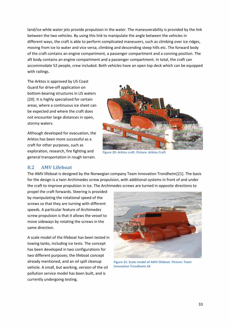
33
land/ice while water jets provide propulsion in the water. The maneuverability is provided by the link
between the two vehicles. By using this link to manipulate the angle between the vehicles in
different ways, the craft is able to perform complicated maneuvers, such as climbing over ice ridges,
moving from ice to water and vice versa, climbing and descending steep hills etc. The forward body
of the craft contains an engine compartment, a passenger compartment and a conning position. The
aft body contains an engine compartment and a passenger compartment. In total, the craft can
accommodate 52 people, crew included. Both vehicles have an open top deck which can be equipped
with railings.
The Arktos is approved by US Coast
Guard for drive-off application on
bottom-bearing structures in US waters
[20]. It is highly specialized for certain
areas, where a continuous ice sheet can
be expected and where the craft does
not encounter large distances in open,
stormy waters.
Although developed for evacuation, the
Arktos has been more successful as a
craft for other purposes, such as
exploration, research, fire fighting and
general transportation in rough terrain.
8.2 AMV Lifeboat The AMV lifeboat is designed by the Norwegian company Team Innovation Trondheim[21]. The basis
for the design is a twin Archimedes screw propulsion, with additional systems in front of and under
the craft to improve propulsion in ice. The Archimedes screws are turned in opposite directions to
propel the craft forwards. Steering is provided
by manipulating the rotational speed of the
screws so that they are turning with different
speeds. A particular feature of Archimedes
screw propulsion is that it allows the vessel to
move sideways by rotating the screws in the
same direction.
A scale model of the lifeboat has been tested in
towing tanks, including ice tests. The concept
has been developed in two configurations for
two different purposes; the lifeboat concept
already mentioned, and an oil spill cleanup
vehicle. A small, but working, version of the oil
pollution service model has been built, and is
currently undergoing testing.
Figure 21: Scale model of AMV lifeboat. Picture: Team Innovation Trondheim AS
Figure 20: Arktos craft. Picture: Arktos Craft

34
8.3 Seascape The idea behind Seascape is to develop a lifeboat
which can be launched to a safe distance from the
platform, but with a lowering rate far lower than free
fall. This is to avoid damage if the water contains ice
lumps or is ice covered. Launching is done by lowering
the lifeboat sitting on the end of a long truss/boom,
which is hinged in the middle, as shown on the figure
below [22]. The boom is lowered and extended, so
that the lifeboat reaches the water a certain distance
from the platform. The lifeboat is an aluminum
construction, and appears more similar to an ordinary
boat than to other lifeboats. Once on the water, the
lifeboat functions as an ordinary boat, with
conventional propeller and steering.
The development of Seascape started in the 1980’s,
and full scale testing was performed 2002-2004. The
tests results are unknown. The concept is currently
believed to be in the prototype phase.
8.4 Polar Haven The Polar Haven concept is a Canadian design, developed for use in an arctic environment by Mad
Rock Marine Solutions Inc. The concept consists of a catamaran hull with an enclosed superstructure,
propelled by two fans of the
hovercraft propulsion fan type.
The concept is under development,
and is awaiting full scale prototype
construction and testing. According
to the manufacturer’s website,
launch of a full scale prototype is
expected to occur in 2013. [23]
8.5 Subevak The submarine evacuation system has not been developed specifically for arctic conditions, but is
nevertheless worth mentioning. The system is based on the use of an underwater survival craft
(submarine) for evacuation from petroleum installations or ships. The submarine is stored in a
submarine bay under the waterline of the installation, for example in the pontoons of a semi-
submersible rig. When evacuation is ordered, the submarine is boarded, the hatches are shut, and
the bay is filled with water. Doors to the sea are opened, and the lifeboat propels itself out of the bay
on a roller system.
Figure 22: Seascape lifeboat and launching system. Picture: Seascape 2000
Figure 23: Polar Haven. Picture: Mad Rock Marine Solutions

35
The concept is described in a patent [1] registered in 2004, by Subevak Systems Inc. However, little
other information is to be found on the system or the company, and the details of the concept and
progress are therefore unknown. It is also unknown whether the concept has been developed further
than what is stated in the patent.
The idea and concept is that the submarine does not come in contact with the weather conditions on
the surface. Issues with wind, waves, low visibility and icing are therefore avoided. At the same time,
it avoids the issues related to floating ice of any concentration. This could potentially make the
evacuation system suitable for arctic use.
The intended endurance of the submarine, i.e. how long it can stay submerged, is unknown. The
patent states that the submarine should be propelled to a predetermined location remote of the
offshore unit. This could imply that a certain infrastructure or refuge location is needed to ensure
transfer of the occupants to a permanent refuge.
Figure 24: The Subevak system. Picture: [1]

36
9 Evaluation The arctic evacuation concepts presented in the previous chapter represent a wide variety of
watercrafts. The Seascape and the Polar Haven can clearly be defined as boats, while the Arktos and
the AMV Lifeboat are more similar to amphibious vehicles. The Subevak concept is more similar to a
military submarine than a lifeboat, and therefore represents yet another approach to the question of
arctic evacuation. The five concepts are essentially designed to perform the same task; evacuation
from a petroleum installation, but in different conditions depending on their intended operational
area within the Arctic. Comparing the concepts could therefore be complicated, and a systematic
approach must be taken.
In chapter 7 of this thesis, a specification was drawn up. The goal of this chapter is to evaluate how
existing concepts hold up to that specification. However, the specification was designed to apply to a
certain environment, which was defined as:
This specification is written to be applicable for lifeboats which are to operate in areas where
the ice conditions vary through the year, and not for areas where a permanent and
continuous ice-cover is present through the summer season. The goal has been to develop a
specification for lifeboats which must be able to operate in open water, in open water with
some ice and in moderate pack ice. Further, the goal has been that launch and survival of the
lifeboat should be possible also in the event that close pack ice is present.
This means that an evaluation with respect to the specification will only illustrate how well the
different concepts can perform in those conditions, conditions which may be different than in the
intended operational area for each concept. However, evaluating if the existing concepts can be put
into use in the mentioned conditions is valuable as a comparison between the different crafts.
9.1 Method The method used for evaluation is to apply a hierarchic weighted evaluation to each of the concepts.
An evaluation hierarchy is established, where all the categories and articles in the specification are
included. For each article, a rating is performed based on best judgment, giving a score on a scale
from one to five. One indicates that the evaluated concept does not comply with the specification
article. Five indicates full compliance. The intermediate values (2, 3, 4) are used to indicate varying
degrees of partial compliance.
Each article is weighted, meaning that compliance with some articles is considered more important
than others. Based on this weighting and the article scores, a score is calculated for the category.
An applicability factor separates applicable articles from non-applicable articles. The factor is set to
zero for articles which are not applicable to the craft in question, or when rating cannot be
performed due to lack of information. When an article is not applicable, the score is also set to zero.
Note therefore that a score of zero does not indicate a lower degree of compliance than a score of
one. The intention of introducing the applicability factor is to avoid that non-applicable articles
influences the total score.
The categories are also weighted. Based on category scores and weighting, an overall score is
calculated for the craft.

37
The calculation method and symbols used are as follows:
.
.
.
,
,
, .
,
, .
,
,
n
n m
n
n m
n
n m
S Score total
n category number
m article number
S Score category n
S Score article n m
w weighting factor category n
w weighting factor article n m
a applicability factor category n
a applicability factor a
.
. . .
. .
.
0 0. : 1
( )
( )
( )
( )
n n m n
n m n m n m
n
n m n m
n n n
n n
rticle n m
a if a Otherwise a
S a wS
a w
S a wS
a w
The evaluation is performed in Excel, with one separate sheet for each craft. The full evaluation
sheets can be found in the appendices. A compressed version of the sheets will be presented and
discussed in this chapter.
9.2 Arktos
Category Weight Score
Temperature 0,15 5,00
Wind 0,10 3,00
Atmospheric icing 0,10 5,00
Sea spray icing 0,20 2,45
Ice 0,30 3,17
Distances 0,15 1,40
Total 3,20
Table 5: Summary of evaluation, Arktos
The Arktos, which is made for and proven in arctic conditions, performs very well in the temperature
and atmospheric icing categories. However, it scores significantly lower in the sea spray icing and
wind categories. Due to its limited endurance of 12 hours, the distance score is very poor. The total
score is 3.20, which is slightly lower than the AMV lifeboat.
As opposed to the other concepts, the Arktos is a well proven craft. It has demonstrated very good
performance in areas where continuous ice and very close pack ice are the main conditions. On the
other hand, the performance in open water and light ice conditions is less impressive. It is only

38
approved for drive off application, meaning that it can only be launched from installations with a very
low freeboard, such as artificial islands.
9.3 AMV Lifeboat
Category Weight Score
Temperature 0,15 5,00
Wind 0,10 3,00
Atmospheric icing 0,10 3,30
Sea spray icing 0,20 3,06
Ice 0,30 3,70
Distances 0,15 0,00
Total 3,65
Table 6: Summary of evaluation, AMV Lifeboat
The AMV lifeboat performs well on the temperature category and quite good on the other
categories. However, due to the early stage of the project and resulting lack of information, several
scores have been marked as not applicable. The foundation for the total score is therefore not as
good as for the Arktos. Still, the AMV lifeboat has the highest total score of the four evaluated
concepts.
The AMV lifeboat project is still in a early phase, and no full size prototype has been built. However,
the concept is promising. The AMV Lifeboat could prove to be a well suited concept for areas with
high ice concentrations or continuous ice. It must therefore be seen as a competitor to the Arktos,
rather than a competitor or alternative to existing lifeboats.
9.4 Seascape
Category Weight Score
Temperature 0,15 2,30
Wind 0,10 4,40
Atmospheric icing 0,10 1,30
Sea spray icing 0,20 2,25
Ice 0,30 3,48
Distances 0,15 3,00
Total 2,85
Table 7: Summary of evaluation: Seascape
The Seascape shows good performance in the wind category, due to its launching system and the
construction and performance of the craft itself. However, the craft has poor resistance to icing, both
atmospheric and sea spray. The total score is therefore relatively low compared to the other
concepts.
The Seascape system has been tested in full scale, and has showed potential. However, in open
water it cannot compete with free fall lifeboats when it comes to time required for launching. In ice
conditions, it shows approximately the same performance as other lifeboats. Further development
could show the Seascape launching system to be more valuable than the craft itself.

39
9.5 Polar Haven
Category Weight Score
Temperature 0,15 3,70
Wind 0,10 3,00
Atmospheric icing 0,10 3,00
Sea spray icing 0,20 2,50
Ice 0,30 3,56
Distances 0,15 0,00
Total 3,20
Table 8: Summary of evaluation, Polar Haven
The Polar Haven project is still in a very early phase, thus very limited information is available. The
foundation for evaluation is therefore also limited. The score is more or less average in all categories,
and the total score is also average.
Due to the unconventional propulsion system and twin hull design, it will be very interesting to see
how the Polar Haven performs when a full scale prototype is ready.
9.6 Subevak The Subevak concept has not been included in the evaluation. The reason for this is that it is a
submarine concept, which is different than the other concepts in virtually all aspects of the design.
Although the task, evacuation from a petroleum installation, is the same for the Subevak as the other
concepts, the approach to the task is so different that a direct comparison would be meaningless.
The amount of information about the concept is also very limited.
The Subevak could be a very promising concept. Issues regarding ice conditions, wind, waves, icing
etc. are all eliminated by performing the evacuation under water. However, a submerged system
meets many other difficult challenges. The underwater environment is lethal to human life, meaning
that if a fault occurs, the effects can be fatal to all occupants. In the case of engine failure, rescue
from a submerged evacuation vessel is virtually impossible, unless the vessel emerges to the surface,
where it is subject to ice, weather, waves, etc. which is not designed to operate in. Last, but not least,
getting a certification and approval for a civilian manned submarine will be a difficult to say the least.
9.7 Conclusion of the evaluation The evaluations of the four concepts show that the total scores are relatively evenly distributed, with
an average of 3.23. The AMV lifeboat has the highest score, with 3.65, which is slightly above the
Arktos and the Polar Haven, and significantly better than the Seascape. The evaluation must be seen
in the light of the conditions which are assumed in the analysis. The assumed conditions may not be
the conditions the different concepts were developed for. However, the evaluation gives an unbiased
ranking of the concepts, where they are evaluated on equal terms.
One aspect which has not been included in the evaluation, is how proven the different concepts are.
However, the Arktos is by far the most tested and proven of the concepts, and is the only one which
has reached serial production.

40
10 Modifications In this chapter, suggestions will be made for improvement of existing evacuation systems. The suggestions will be limited to apply to conventional and free fall lifeboats, meaning that improvements to the concepts described in chapter 8 will not be discussed. The intention of the improvements is to improve the performance of existing conventional and free fall lifeboats in an arctic environment. Ideally, the result of the improvements would be full compliance to the specification set up in chapter 7. This would be very extensive. Different areas of improvement must therefore be prioritized, to select the improvement measures which are of highest importance.
In chapter 6, a what-if analysis was performed. The analysis, for conventional lifeboats and free fall lifeboats, can be found in appendix X. For each item in the analysis, recommendations for improvements are listed, and the criticality of the item is determined. The criticality can be used to rank the importance of implementing the recommendations. The analysis did not result in any items having a criticality of 9, which is the highest possible criticality in the analysis. However, a number of items have a criticality of 6, the second highest possible criticality.
By inspecting the items of the analysis with a criticality of 6, we find that the items with a high criticality are, with one exception, the same for conventional and free fall lifeboats. We can sum up the appurtenant recommendations for improvement in a short form:
1. Measures should be implemented to ensure that the temperature of moving davit components is kept higher than the ambient temperature.
2. Free fall only: The secondary launching method should be improved to function independent of external electrical power and to launch the lifeboat without a forward heeling angle.
3. Alternative evacuation methods should be established for use when the ice concentration is higher than the lifeboats can operate in.
4. The engine power should be increased to improve performance in open drift ice. 5. The hull shape should be modified to improve the ice breaking capability of the lifeboats. 6. The hull structure should be reinforced in the waterline area, to avoid structural damage in
contact with ice. 7. The propeller and propeller nozzle should be modified to withstand contact with ice. 8. Measures to prevent sea spray icing effects should be implemented.
10.1 Temperature of moving components To avoid freezing and immobility of moving components, their temperature can be controlled directly or indirectly.
If the direct approach is taken, the temperature must be controlled and altered locally on the component, by use of heating elements. These heating elements must be mounted externally or internally on the component it is meant to heat, along with a device for temperature monitoring. The temperature can then be regulated automatically. The advantage of the direct heating method is that it can be installed with little or no modification of the lifeboat launching arrangement, other than the heating and control components. This allows the launching operation to be performed uninterrupted by the heating arrangements. On the other side, if there are many components to be heated, the system will be relatively complex. Local external heating systems are also vulnerable to damage.
If the indirect approach is taken the moving component must be located (stored) in a heated environment. For lifeboat davits, this would mean that an enclosure or garage must be built around the davit. By monitoring and heating the air inside of the enclosure, the temperature off all components within the enclosure can be regulated. The advantage of the heated environment

41
approach is that it heats the entire lifeboat launching arrangement to the same temperature, and protects against atmospheric and sea spray icing. It is also a relatively simple system with a single heating device. On the other side, inclosing the launching arrangement in an enclosed lifeboat garage will complicate the launching operation, as the garage must be opened before launching can take place.
As the indirect heated environment solution provides heating of all components, both lifeboat and launching arrangement, and also protects against icing, this solution is recommended.
10.2 Secondary launching method For free fall lifeboats, which cannot be launched by free fall if ice is present, improvement of the secondary launching method is recommended. The improvement should include implementation of an uninterrupted power supply or energy storage system for the lifting boom, and a heeling angle leveling arrangement to reduce the forward heeling angle during lowering.
On existing free fall lifeboat systems, the lifting boom for the secondary launching system is tilted by a hydraulic system which requires electricity from the installation to function. In a blackout situation, where the installation power supply is down, lowering of the lifeboat is therefore not possible. This should be solved by the implementation of an independent system to deliver hydraulic pressure to the lifting boom cylinders. The system can be either hydraulic or electric. In the hydraulic version, oil under pressure is stored in accumulators. When lifting is required, the hydraulic cylinders are powered by oil pressure from the accumulators. In the electric version, a battery bank provides electrical power to a hydraulic power unit, which provides hydraulic pressure to the cylinders.
The hydraulic version of the system is assumed to be more reliable and require less maintenance. This version is therefore recommended.
Modern free fall lifeboats are stored on skids in the davit, with a forward heeling angle of approximately 35 degrees. This angle is maintained during lowering with the secondary launching arrangement, and the result is that the lifeboat reaches sea level with the bow first. This is not ideal, and should be avoided. The lowering is performed by two wires, one on each side, connected to two-leg wire assemblies, which are connected to four lifting points on the lifeboat. By increasing the number of lowering wires to four, or by rearranging them so that the one wire is connected to the aft lifting points and the other to the forward lifting points, the forward heeling angle can be reduced during the lowering. The aft wire lowering rate must be higher than the forward. This can be solved by increasing the drum diameter for the aft lowering wire, or by increasing the number of winches from one to two.
To ensure that the system is not too complex, a system with one aft lowering wire and one forward lowering wire, controlled by a common winch but with different drum diameters, is recommended.
10.3 Alternative evacuation method If the ice concentration around the installation is forecasted to be too high for the lifeboats to be used, the installation must either be equipped with a secondary means of evacuation usable in high ice concentrations, or evacuate the personnel before the conditions reaches the limit of the lifeboats. If this is a probable scenario, an upgrade of the evacuation material is needed. The issue only arises if the lifeboats cannot be used, and modification of the lifeboats can therefore only prevent the issue from arising, but not provide a solution.
The recommendation is therefore a general upgrade of the evacuation equipment to systems fit for use in higher ice concentrations.

42
10.4 Engine power Existing lifeboats are generally equipped with engines capable of propelling the lifeboat at the required speed of six knots, but little more. The engine power is therefore limited. In ice conditions, increased engine power can be an advantage, and can increase the maneuverability of the lifeboat. A significant increase of the engine power is therefore recommended.
10.5 Hull shape The hull shape is important for maneuverability in high ice concentrations, and vital for the ability to
break ice. However, modification of the hull shape on existing lifeboats is very comprehensive. It is
highly doubtful if such modification serves any purpose, compared to development of new lifeboat
models.
Hull modification on existing lifeboats is not recommended. That being said, hull shape is very
important for propulsion in ice, and should therefore be given much consideration in the
development of future lifeboat models.
10.6 Hull structure strengthening When a lifeboat hull comes in contact with larger ice floes, large forces act on the relatively light
lifeboat from the heavy ice floe. This occurs in the vicinity of the waterline. It is therefore vital that
the lifeboat has enough structural strength to withstand such impacts. Free fall lifeboats, which are
built to withstand impact with the water surface at a high speed, may have enough structural
strength to withstand the loads from ice floes. The situation for conventional lifeboats is more
uncertain. Therefore, the impact loads from ice floes on lifeboats should be investigated. Based on
this, the lifeboats can be strengthened if required. Structural strengthening of existing lifeboats,
although comprehensive, is feasible and has been performed. It is therefore recommended that the
loads are investigated and strengthening performed if required.
10.7 Propulsion equipment In contact with ice, the propeller experiences great load, which can cause damage to the blades and the hub. The protective grid which is installed on lifeboats will protect the propeller from contact with large pieces of ice, but the pieces which are allowed through the grid can also cause damage. The propeller can also be damaged if large pieces of ice are sucked into the protective grid, blocking the water flow to the propeller. This can cause loads on the propeller which are of the same magnitude as contact loads. Due to the requirements in existing regulations, propellers are dimensioned to withstand impacts with floating debris. Investigations or test can determine if this is sufficient for the propeller to survive ice contact.
To avoid damage to the propeller, it should have a blade thickness and hub size which allows it to withstand the loads which occurs in contact with ice. Investigations to determine if this is already fulfilled should be performed and replacement of the propellers are recommended if the blade thickness and hub size are insufficient.
10.8 Sea spray icing Sea spray icing can be a threat to the stability of lifeboats. To reduce the ice accretion on the
superstructure of existing lifeboats, the superstructure surface can be coated with low friction paint,
which will delay the initiation of ice accretion. Unnecessary protruding appendages on the
superstructure should be avoided, removed or relocated.

43
11 Suggested new concepts In this chapter, a few concepts will be suggested based on the conditions describe in chapter 3. The
concepts will be briefly described and discussed.
11.1 Concept 1: The Arctic Free Fall Lifeboat Free fall (FF) lifeboats have been used for over 25 years on offshore installations. They are capable of
evacuating a large number of people in a very short time compared to conventional lifeboats, and
the risk of incidents occurring during the launch is low. After impact, the lifeboat has a positive
headway, which ensures that the it is not dead in the water under the installation in the case of
engine failure. In open water, the free fall lifeboat is therefore the safest and most efficient
alternative for maritime evacuation. This has also been stated by The Petroleum Safety Authority
Norway [24]:
The current free-fall technology with skid launched lifeboats and drop lifeboats is the safest
method for ensuring that the means of evacuation moves personnel away from the offshore
facility as quickly as possible. The Petroleum Safety Authority Norway (PSA) considers free-fall
life boats to be the best technology available at present within lifeboat evacuation on the
Norwegian shelf.
When using the free fall launching method, the lifeboat reaches the water surface with a high vertical
speed. The kinetic energy of the lifeboat is therefore large, and impact with floating, solid objects
could be catastrophic to its structural integrity. If there is a risk of sea ice in the launching zone, free
fall launching must therefore be avoided. The solution is then to utilize the secondary launching
method, which in many ways is similar to the lowering of a conventional lifeboat, and provides a
controlled lowering of the lifeboat to the surface of the sea.
In southern areas of the Arctic, the water is free from ice floes and growlers for a significant part of
the year. These are also the areas where much of the oil exploration and production will take place
in the years to come. In the ice-free season, free fall lifeboats would be preferable on installations in
these areas, due to their superiority in comparison to conventional lifeboats. By using and improving
the secondary launching method, it should also be possible to develop a satisfactory solution for
launching of free fall lifeboats in the ice season. This leads to a concept for a new lifeboat system,
which functions as a free fall system in the ice-free season, but which is also fully usable in the ice
season. This could be achieved by improving the secondary launching method and equipping the
lifeboat itself with features which enables it to operate in a wider range of ice conditions.
A brief description of the proposed concept:
- The capacity and size of the lifeboat should be sufficient to function as means of evacuation
on oil rigs, platforms, etc.
- During the ice-free summer season, the lifeboat should be able to operate as a fully
functioning free fall lifeboat. The exterior design of the lifeboat is therefore forced to be
quite similar to an ordinary free fall lifeboat of the same capacity.
- During the ice season, the lifeboat should be launched by the secondary launching method,
which involves lowering the lifeboat to sea level by means of a system of wires, winches and
hooks. The lowering method should be improved to function as the main launching method
during the ice season.

44
- In terms of requirements and regulations, the lifeboat should fulfill all requirements which
apply to free fall lifeboat. Preferably, the new DNV-OS-E406 standard should be used, as this
is the newest and strictest offshore lifeboat standard, and compliance with this standard will
enable the lifeboat to operate on the Norwegian continental shelf.
- The lifeboat should be stored in a heated environment to prevent malfunction as an effect of
the cold climate, and to prevent atmospheric icing.
- The lifeboat should be designed to avoid ice accumulation (sea spray icing) and to remove
the ice efficiently and safely if a layer of ice accumulates.
- Maneuvering should be possible in close pack ice conditions (8/10). This should be achieved
through optimizing the hull shape and propulsion equipment for ice maneuvering.
- The lifeboat should be able to break ice of reasonable thickness.
- If the lifeboat encounters very close pack ice or compact ice, it should preferably be able to
climb onto the ice edge and have limited maneuvering capability on the ice.
- With respect to the distances and transit times which exists in the Arctic, the fuel capacity of
the lifeboat should be increased compared to what is required in the existing regulations
By designing the lifeboat around these key points, the result will be a lifeboat which fulfills the
requirements set up in the specifications found in chapter 5 of this thesis, and which is suitable for
areas where the dominant ice conditions are in the range of open water (0/10) to close pack ice
(8/10).
This concept will be described and discussed further in chapter 12.
11.2 Concept 2: The arctic conventional lifeboat While free fall launching of lifeboats is preferable in open waters, it cannot be performed in ice
infested waters due to the high vertical velocity and the serious consequences of an impact with ice.
In partially ice covered water, lifeboats must therefore be launched in a more controlled fashion. The
conventional launching method, where the lifeboat is lowered to sea level via a system of winches,
pulleys, wires and hooks, and released when afloat, is suitable for this environment. A lifeboat
launched by the conventional method could therefore be a good solution in areas where the risk of
ice floes, growlers or pack ice is present most of the year.
During periods where the ice concentration is open drift ice or lower, the maneuverability of
ordinary non-arctic lifeboats is satisfactory [25]. In higher ice concentrations, the ice will prevent the
boat from making progress, particularly if the majority of ice is large ice floes. If the majority of ice
floes are smaller, some improvement can be gained by increasing the engine power, and thereby the
bollard pull. Ice breaking capabilities or unconventional propulsion methods can be introduced to
improve maneuverability in higher ice concentrations and between larger ice floes.
One unconventional propulsion method, which has been suggested and developed for propulsion in
ice conditions, is Archimedes screw propulsion. This is used on the AMV lifeboat described in chapter
6. The propulsion gear consists of two rotating cylinders with protruding, helical blades along the
entire length to provide traction. Counter-rotating the cylinders provides a forward force which can
propel the craft forward. Steering is performed by regulating the relative rotational speeds for the
cylinders. The craft can also move sideways by rotating the cylinders in the same direction, and
reverse by changing the direction of the rotation. Archimedes screw propulsion is well suited for

45
propulsion on continuous layers of ice or ice floes, and could be utilized for on-ice propulsion for an
otherwise conventional lifeboat.
A brief description of the proposed concept:
- The capacity and size of the lifeboat should be sufficient to function as means of evacuation
on oil rigs, platforms, etc.
- During seasons with open drift ice, very open drift ice or open water, the lifeboat should
function similarly to a conventional lifeboat.
- During seasons with close pack ice, the lifeboat should be able to propel itself through the
water if possible, and climb onto the ice if progression is no longer achieved in the water.
This should be achieved by Archimedes screw propulsion.
- During seasons with very close pack ice or a continuous layer of ice, the lifeboat should be
launched directly onto the ice and be able to propel itself and have sufficient steering on the
ice by means of two large Archimedes screws, one on each side of the craft.
- The screws should be accounted for in the hull design, so that the hull is shaped to fit
between the screws. During operation in open water, the volume in between the blades on
the screws should be filled by an inflatable device to reduce drag.
- In terms of requirements and regulations, the lifeboat should fulfill all existing requirements
which apply to conventional lifeboats.
- The lifeboat should be stored in a heated environment to prevent malfunction as an effect of
the cold climate, and to prevent atmospheric icing.
- During lowering, measures should be implemented to avoid extensive horizontal movement
of the lifeboat.
- The lifeboat should be designed to avoid ice accumulation (sea spray icing) and to remove
the ice efficiently and safely if a layer of ice accumulates.
- With respect to the distances and transit times which exists in the Arctic, the fuel capacity of
the lifeboat should be increased compared to what is required in the existing regulations
By designing the lifeboat around these key points, the result will be a lifeboat which fulfills the
requirements set up in the specifications found in chapter 5 of this thesis. It will be suitable for areas
where the ice concentrations range from open water to continuous ice depending on the season, but
where the risk of ice is present for most of the year.
11.3 Concept 3: The arctic survival vehicle In the most northern areas of the Arctic, where continuous ice or very close pack ice is present
through the entire year, floating survival crafts are of little use. This is also the case for areas where
the summer season only provides slightly lower ice concentration than in winter. When floating
survival crafts cannot be used, other survival crafts must be used to provide opportunities for
evacuation from petroleum installations. When navigating through water is not an option, the
solution is to travel on top of it. The surface of continuous ice is relatively flat, with steep ice ridges
breaking the surface. However, one cannot simply utilize ordinary vehicles as one would in the
Antarctic, due to the risk of breaking through the ice or encountering open stretches of water. A
survival craft for use on the ice must also be able to cross significant stretches of open water, drift ice
and pack ice.

46
An Arctic survival vehicle must be propelled in a way completely different from lifeboats, but must
still be able to propel itself through water. Two different approaches can be taken:
- One set of propulsion equipment, which is able to propel the vehicle through water and on
top of the ice. This is the approach taken by the designers of the AMV lifeboat.
- Two sets of propulsion equipment, where the operator switches between the systems when
the vehicle moves from one element to the other. This is the approach taken by the team
behind the Arktos craft.
Several different means of propulsion are available for propulsion on ice. In Table 9, a short
presentation of the alternatives, along with advantages and disadvantages, is provided:
Description Advantages Disadvantages
Single pair of tracks A single pair of tracks, mounted on the sides of the vehicle, stretches along the length of the vehicle.
Well proven Low complexity
Not very suited for climbing onto ice floes
Twin pair of tracks, single vehicle
Two pairs of tracks mounted in the ends of one vehicle
Somewhat proven in arctic conditions Very flexible
Twin pair of tracks, twin vehicles
Two pairs of tracks mounted on two interconnected vehicles.
Good maneuverability Relies on complex and vulnerable joint between the vehicles
Archimedes screws Counter-rotating Archimedes screws mounted parallel to each other and the centerline of the vehicle.
High gripping power on ice
Novel design, not proven under arctic conditions
Propulsion fan and skids
Aircraft-type propulsion fans in combination with skids.
High speed Low complexity
Poor fuel efficiency Limited thrust
Propulsion fan and air cushion
Aircraft-type propulsion fans in combination with an air cushion for lift.
High speed Propulsion possible over any surface
Air cushion control is complicated Poor fuel efficiency
Table 9: Propulsion methods for use on ice
The twin pair of tracks, single vehicle concept should be considered for an arctic survival vehicle. A
single vehicle with one set of tracks in each corner, where the tracks extend beyond the vehicle body
in all directions and each set of tracks can be controlled separately, is known to perform well on the
ice in the Antarctic. It could also prove to be very well suited for climbing onto ice floes and a large
vehicle body between the tracks can provide sufficient buoyancy.
The construction, function and performance of an arctic survival vehicle is bound to be very different
from existing lifeboats and lifeboat-like designs. Therefore, details of a vehicle concept will not be
discussed further in this thesis.

47
12 The Arctic FFL, concept description In the previous chapter, three concepts were described, each designated for specific ice conditions.
Concept number one, the Arctic Free Fall Lifeboat, will be developed further in this chapter. The
name of the concept is shortened to the Arctic FFL for simplicity.
12.1 Goal and focus, general description The concept has been presented in the form of a list of features in the previous chapter. The goal of
this chapter is to develop and describe a lifeboat system which fulfills the requirements on that list,
as well as the specification set up in chapter 7. In addition, the lifeboat system should also be able to
fulfill all existing requirements for lifeboats, such as the DNV-OS-E406. However, compliance with
existing requirements will not be discussed in detail in this chapter.
12.2 Main dimensions and capacities To determine the main dimensions and capacities for the Arctic FFL, it is useful to look at boats with a
similar purpose and capacity. In Table 10, the capacity and main dimensions are listed for four
lifeboat models currently in use in the oil industry. These four will be used and referred to as the
reference boats. It should be noted that only the FF1200 is designed to meet the new requirements
of DNV-OS-E406, while the others are designed to fulfill the SOLAS requirements.
Manufacturer Model Capacity (persons)
Free fall height [m]
Length L o.a. [m]
Breadth B [m]
Height H [m]
L/B L/H
Umoe Schat-Harding
FF1000 64 30 12,6 3,4 4,3 3,7 2,9
Umoe Schat-Harding
FF1200 70 33 16,0 (approx.)
3,9 (approx.)
4,9 (approx.)
4,1 3,3
Norsafe GES 40 64 30 12,0 2,8 3,4 4,3 3,5
Norsafe GES50 MKII
70 37 15,0 3,8 4,4 3,9 3,4
Table 10: Dimensions of lifeboats
Currently, free fall lifeboats in use in the oil industry, such as the four models described in Table 10,
have a capacity of 64 to 70 persons [26] [27]. As described in the previous chapter, the capacity of
the Arctic FFL should be sufficient to be used for evacuation on petroleum installations. The capacity
is therefore set to 70 persons.
When determining the length of the Arctic FFL, the intended bow design should be kept in mind. An
ice breaking bow of the suggested type must be relatively narrow and shallow, which means that to
achieve the necessary displacement while maintaining a modest draught, the lifeboat should be
quite long. The overall length of the vessel is therefore set to 16.0 meters, which corresponds to the
length of the longest of the reference boats, the FF1200.
The breadth of the Arctic FFL is set on basis of the length and a length to breadth ratio of 4.0, giving a
design breadth of 4.0 meters.
The height of a free fall lifeboat depends on the location of the conning position, as the cockpit is
normally the highest point. On the Arctic FFL, the conning position will be located near the bow,

48
which allows it to be placed slightly lower than if it was located abaft. The length to height ratio is
therefore set to 3.55, giving a height of 4.5 meters.
Capacity 70 persons
Length overall 16.0 meters
Breadth overall 4.0 meters
Height overall 4.5 meters
Table 11: Main dimensions for the Arctic FFL
12.3 Hull design The hull is designed in the free version of DELFTship, a computer program for hull form modeling and
calculation of hydrostatical data [28]. It would have been advantageous to use the more advanced
full version of the program, but due to issues with the NTNU license for the program, it has not been
available. DELFTship is used to produce a simple three-dimensional model of the hull, which
illustrates the intended hull form and can be used to calculate a range of hydrostatical data. The hull
model can be found on the CD attached to this thesis.
The hull design is initiated by defining the length and breadth, from which DELFTship produces an
initial model of a general hull. The position of points on a control net is then extensively altered
manually to obtain the intended hull form. Stations, buttocks and waterlines are altered
automatically when points on the control net are moved. Hydrostatical data can also be obtained
during the design process as input for further changes. Finally, when the hull model has taken the
desired shape, the waterline for different loading conditions can be found on basis of the weight
displacement.
Figure 25: The Arctic FFL. Illustration generated in DELFTship.
For the Arctic FFL, as for many lifeboats, there is no clear transition between hull and superstructure.
Therefore, the design of the hull and superstructure is performed simultaneously in DELFTship, with
the superstructure as a natural continuation of the hull. However, in terms of the way surfaces are
produced in DELFTship, the inclining top surface is defined as a deck.

49
The final shape of the hull is determined by the desired properties of the finished hull. These
properties have significantly influenced the shape of the hull and superstructure, but will be
discussed separately. Figure 25 shows the finished hull design. More illustrations, including line
drawings and hydrostatical data can be found in appendix C.
12.4 Storage As discussed earlier in this thesis, there are several issues which can be avoided by storing a lifeboat
in an enclosed and heated environment. Examples are problems with atmospheric icing and starting
of engines at low temperatures. The Arctic FFL should therefore be stored within a heated lifeboat
garage.
The garage must be large enough to contain the lifeboat and the davit, and must be heated to a
temperature of no less than freezing. On the sides of the davit and under the davit, permanent walls
will not be in the way for the launch. In the front off the lifeboat and within the reach of the lifting
frame however, the garage walls and ceiling must consist of doors or movable walls. When launching
of the lifeboat is required, the garage must be opened within a period of time short enough to avoid
delay of the launching operation. This means that the doors must be opened within the time it takes
to complete boarding of the lifeboat. The doors should not rely on external power for operation, and
should therefore be opened by gravitational force alone. Alternatively, soft walls which can be rolled
up when required could be used, as these can be opened by means of the force from a loaded spring
or a small amount of stored hydraulic pressure.
12.5 Launching The Arctic FFL launching system should be designed to operate in two modes; free fall launching in
the ice-free summer season, and conventional lowering in the winter season.
In the free fall launching mode, the lifeboat should behave as any other skid-launched, free fall
lifeboat. To achieve this, the hull and superstructure must be designed to be quite similar to proven
free fall lifeboat designs. This is the main reason that free fall lifeboats are used as reference boats,
and that the design of the lifeboat is not radically different from existing free fall lifeboats.
In the secondary launching mode, the lifeboat is lowered to sea level while suspended from winches
on the davit, at a limited speed. For existing lifeboats, the secondary launching method is primarily a
recovering method, which also can be used for launching. It is, at least by regulation, not intended
for launching of a fully loaded lifeboat. For the Arctic FFL, the secondary launching method should be
improved to allow it to be used as launching method for significant parts of the year. The capacity
and structural strength of the secondary launching arrangement should therefore be designed and
tested for the loads imposed by a fully loaded lifeboat, to ensure that safe and reliable launching can
be performed when required.
Free fall lifeboats are stored in the davit with a forward heeling angle of approximately 35 degrees.
The secondary launching method lifts the lifeboat from the skids, moves it forward a distance of
approximately one boat length and lowers it to sea level without altering the forward heeling angle.
This causes the lifeboat to reach the water surface bow first. During lowering, this angle should be
leveled out by the launching arrangement, so that the lifeboat has no forward heel when reaching
sea level. On existing systems, two lowering wires are connected to two-leg wire assemblies, which
are connected to four lifting points on the lifeboat, two on each side. If instead a different approach

50
is taken, with one wire for each lifting point, the forward heeling angle could be evened out during
lowering, by lowering the two aft wires at a slightly higher speed than the two forward lowering
wires. Alternatively, the lifting wires could be rearranged so that one wire is connected to the aft
lifting points and the other to the forward lifting points. The aft wire lowering rate must be higher
than the forward. This can be solved by increasing the drum diameter for the aft lowering wire, or by
increasing the number of winches from one to two.
To ensure that the system is not too complex, a system with one aft lowering wire and one forward lowering wire, controlled by a common winch but with different drum diameters, is recommended.
Launching of the lifeboat should be possible without assistance from external systems. On existing
systems, the lifting frame is tilted forwards by a hydraulic system, powered by electricity from the
installation. To ensure successful lowering in a blackout (dead ship) situation, the lowering winch and
hydraulic cylinders controlling the lifting boom should be self-sufficient for at least one launch. This
can be achieved by storing mechanical energy in hydraulic accumulators located on the davit. It could
also be achieved by giving the hydraulic unit a separate electrical supply in the form of a battery bank
or designated generator set.
The launching operation should be controlled by the lifeboat helmsman from his position in the
lifeboat, without assistance from operators on the installation. This could be achieved by controlling
the launch through a wireless remote control system running on an uninterrupted power supply.
12.6 Weight estimation
12.6.1 Hull
A rough estimate of the weight of the hull could be calculated from the total outer hull area. This is
done by finding the outer area of the hull, the density and average thickness of the material used.
These values are then multiplied to find the weight. Additional structural weight, such as beams,
reinforcements, foundations, tanks etc which are also part of the hull structure, are accounted for by
introducing an additional weight coefficient, under the assumption that the weight of the mentioned
parts is proportional to the weight of the hull skin. For the Arctic FFL, the average thickness value and
additional weight coefficient are unknown. The values are set based on loose assumptions, to show
the calculation method, but due to the poor quality of these values, the accuracy of the result is
uncertain.
The total area of the hull (superstructure included) is found by totally submerging the DELFTship
model and calculate the resulting submerged area. The total area for the Arctic FFL is approx. 182 m2.
The hull skin weight can be found by multiplying the area with the average thickness of the hull
laminate and the density of the material.
The material used in the Arctic FFL should be fiberglass reinforced polyester (FRP). The density of FRP
depends on the composition of the laminate, i.e. the amount of fiber compared to resin. However,
for high tensile strength FRP laminates, the density is within the range of 1.8 to 2.0 tons per cubic
meter. For the purpose of weight calculation, the density is assumed to be 2.0 tons per cubic meter.
The average thickness of the laminate is set to 15 millimeters. The additional weight coefficient is set
to 1.33, assuming that the weight of stiffeners, beams, tanks, foundations, etc. is one third of the hull
skin weight.

51
2
3
182[ ]
15[ ] 0,015[ ]
2,0[ ]
1,33
Hull
Hull
Hull
FRP
add
Hull
Hull
FRP
add
Hull Hull Hull FRP
H
M Mass of thehull
A Hull area
t averagethickness of hull laminate
Density of FRP
c Additional weight coefficient
A m
t mm m
ton
m
c
M A t
M
(182 0,015 2,0) 1,33 7,3[ ]ull ton
12.6.2 Diesel engine
According to Design of Advanced Marine Vehicles [29] the weight specific power of high speed diesel
engines is approx. 400 kW per ton. To allow for the weight of gear box, auxiliary systems, propeller
and other equipment directly related to propulsion, the calculated engine weight is given an addition
of 40%. Based on this, we can easily calculate the assumed weight of the engine based on its power.
,
200[ ]
400[ ]
1,40
1 1200 1,40 0,70[
400
engine
Engine
HSD
aux
Engine
HSD
aux
engine Engine aux
HSD
M Enginemass
P Engine power
c weight specific power high speed diesel engine
c additional weight coefficient
P kW
kWc
ton
c
M P cc
]ton
12.6.3 Equipment
Lifeboats are only equipped with the most necessary equipment, such as seats and navigational
equipment. This weight is difficult to estimate, and is assumed to be 1.5 tons.
.
. 1,5[ ]
Equip
Equip
M Weight of onboard equipment
M ton
12.6.4 Deadweight
The deadweight for a lifeboat consists of the weight of people on board, the weight of fuel and the
weight of food and water. These are calculated separately and added to find the total deadweight.

52
The weight of people on board is calculated on the basis of an average weight. Here, the average
weight is set to the same as in DNV-OS-E406, which is 100 kg per person. The capacity of the lifeboat
is 70 persons.
,
,
,
, ,
,
100[ ]
70[ ]
100 70 7000[ ] 7,00[ ]
P tot
P one
P
P one
P
P tot P one P
P tot
M Total weight of peopleonboard
M Weight of one person
n number of peopleonboard
kgM
person
n persons
M M n
M kg ton
The weight of fuel is calculated on the basis of maximum engine power, assumed specific fuel
consumption (sfc) and a maximum operating time of 48 hours, whereof 44 hours at 60% of maximum
engine power, according to the specification set up in chapter 7.
100%
60%
100%
60%
100% 60%
,
,
4[ ]
44[ ]
200[ ]
0,200[ ]
(
fuel
Engine
Engine
fuel
M Weight of fuel
t operating time full speed
t operating time reduced speed
P Maximumengine power
sfc sepcific fuel consumption
t h
t h
P kW
kgsfc
kWh
M t t
0,6)
(4 44 0,6) 200 0,2 1216[ ] 1,22[ ]
Engine
fuel
P sfc
M kg ton
The weight of food and water on board is calculated on basis of the number of people on board, and
the necessary amount of food and water per person per day. The amount of water is set to two liters
per person per day, and the amount of food is set to 1 kg per person per day. As according to the
specification set up in chapter 7, the maximum intended operational time is set to three days.

53
,
,
,
, ,
3 1 4[ ]
70[ ]
72[ ] 3[ ]
4 70
FW
FW one
P
FW one
P
FW FW one P
M Total weight of fuel and water
M Weight of fuel and water one person oneday
n number of peopleonboard
t maximumoperational time
kgM
person day
n persons
t h days
M M n t
3 840[ ] 0,84[ ]kg ton
The total deadweight is calculated on basis of the calculated weights
,
7,00 1,22 0,84 9,06[ ]
P tot fuel FWDWT M M M
DWT ton
12.6.5 Total weight
The total weight of the Arctic FFL is summed up from the calculated weights.
.
7,3 0,7 1,5 9,1 18,6[ ]
Boat
Boat Hull Engine Equip
Boat
M Weight of fully loaded lifeboat
M M M M DWT
M tons
The calculated weight is based on assumptions. Some assumptions are correct, while others are very
uncertain. Therefore, the calculated weight is not to be taken as an accurate description of what the
lifeboat would weigh if it was built. However, the calculations describe the method for finding the
weight at an early design stage. By comparing with the reference boats used earlier in the chapter,
we find that the calculated weight is not too far off. The weight of the Umoe Schat-Harding FF1000
for example, is 11.1 tons plus the weight of the people on board. If we deduct the weight of the
persons on board from the calculated 18.6 tons of the Arctic FFL, we end up at 11.6 tons, which is
relatively close to the weight of the FF1000.
12.7 Operation in ice The Arctic FFL should be capable of maneuvering through close pack ice (8/10), which corresponds to
ice covering 80% of the water surface. Model tests indicate that existing lifeboats in use in the oil
industry, both conventional and free fall, have very limited or no maneuvering capability in ice
conditions above open drift ice (6/10) [25]. The maneuverability is slightly increased if the ice
condition is combined with waves.
12.7.1 Bow
The Arctic FFL is designed with a V-shaped bow which is changed to a narrow flat keel well below the
waterline, as illustrated on the bodyplan view from DELFTship. The flat section will be discussed later
in this chapter. The narrow V-shaped bow has two intentions.

54
Figure 26: Bodyplan view from DELFTship
Firstly, it provides improved progress in slush ice and low ice concentrations, by leading the ice away
from the path of the lifeboat, with as little resistance as possible due to the low entrance angle. The
force from the ice is lead in a more transverse direction than on an ordinary bow. Although this
reduces the resistance from the ice, it will require that the bow is reinforced to withstand the
transverse load.
Secondly, it works as an icebreaking bow. The intention is not to break continuous, thick ice or large
ice flows, but to break thinner layers of ice and to break small ice floes away from each other. One
example is pancake ice, which consists of many small ice floes, floating next to each other or frozen
together by a thinner layer of ice. An ordinary lifeboat bow would usually not be able to maneuver
through such ice. The Arctic FFL, with the narrow V-shaped bow will be able to break its way through
the ice at a limited speed. As on a larger icebreaker, the lifeboat must climb onto the ice to transfer
its weight onto the ice edge. When enough weight is transferred to the ice, it will break under the
load, and the boat is able to move forward.
To climb onto the ice, the ice resistance must be overcome by the propeller thrust. The ice resistance
is the horizontal force which works on the boat when it encounters an ice edge, and counters the
boats effort to climb onto the ice. Therefore, if the ice resistance is reduced, the lifeboats ability to
climb onto the ice will be improved. The ability to climb onto the ice is vital, as the longer up on the
ice floe the lifeboat is positioned, the more of the boat weight is supported by the ice. When the
amount of weight in the ice reaches the limit for what the ice can withstand, it breaks and allows the
lifeboat to go forward. Therefore, when the ice resistance is reduced, the amount of ice which can be
broken is increased.
The geometry of the bow is vital to reduce the ice resistance. The smaller the stem rake angle is (i.e.
more horizontal stem), the lower the ice resistance. The exact thickness of ice which can be broken
by the lifeboat will vary on the composition and structure of the ice.
The propeller thrust, which is determined by the engine power, is also important for the ice breaking
capability. When the engine power is increased, the amount of ice resistance which can be overcome

55
is also increased, and thereby the ice breaking capability. The engine power will be discussed later in
this chapter.
12.7.2 Very close pack ice or continuous ice
When a lifeboat encounters ice which is to dense to maneuver through, and to thick to break, it has
run out of options in terms of navigating through water. In this situation, existing lifeboats must
simply lie still in the water, and wait for rescue. This could be dangerous in two ways. Firstly, if this
occurs to close to the installation from which the lifeboat was launched, the lifeboat has failed its
primary task; evacuating the crew to a safe distance from the installation. Secondly, if the lifeboat
hull is not constructed to withstand ice forces, the pack ice could trap the lifeboat between ice floes
and impose very large forces on the hull. The effect could be severe structural damage from crushing,
and eventually total loss of the lifeboat.
The crushing effect can be avoided by designing the hull to direct the forces from the ice in the
correct direction. The effect of large forces from the ice will then not be crushing, but lifting of the
lifeboat. This approach has been well known since it was proven by the Arctic vessel Fram from 1893
to 1896 [30]. The main idea is to design the hull without vertical hull sides below the waterline, and
to reinforce the hull to avoid severe deformation from the ice forces. Most existing lifeboats have a
hull form with a rounded shape below the waterline, and ice crushing is therefore not a severe
problem for lifeboats. Nevertheless, it is an issue which must be taken into account when designing
and dimensioning the hull structure.
As mentioned, if a lifeboat is trapped in ice which it cannot navigate through, and this occurs within a
short distance from the installation, the lifeboat has failed its primary task; evacuating the occupants
to a safe distance. Existing lifeboats have no options left when the ice conditions are too heavy for it
to navigate in, other than to wait for rescue. It therefore seems as it would be advantageous to find a
way for the lifeboat to climb onto the ice edge and continue moving away from the installation as a
vehicle. Although this may only be achievable on flat ice floes, and only in a straight direction, it
could be enough to reach a safe distance from the installation.
The bow of the Arctic FFL is designed to break ice, by pushing the bow onto the ice edge by use of
propeller thrust. If the propeller thrust is large enough, the flat section under the bow will reach the
ice edge. At that point, about one third of the lifeboat length is actually positioned over the ice, but it
is not likely that the propeller provides enough thrust to move the lifeboat further.
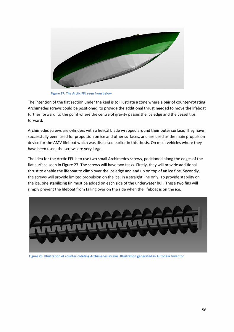
56
The intention of the flat section under the keel is to illustrate a zone where a pair of counter-rotating
Archimedes screws could be positioned, to provide the additional thrust needed to move the lifeboat
further forward, to the point where the centre of gravity passes the ice edge and the vessel tips
forward.
Archimedes screws are cylinders with a helical blade wrapped around their outer surface. They have
successfully been used for propulsion on ice and other surfaces, and are used as the main propulsion
device for the AMV lifeboat which was discussed earlier in this thesis. On most vehicles where they
have been used, the screws are very large.
The idea for the Arctic FFL is to use two small Archimedes screws, positioned along the edges of the
flat surface seen in Figure 27. The screws will have two tasks. Firstly, they will provide additional
thrust to enable the lifeboat to climb over the ice edge and end up on top of an ice floe. Secondly,
the screws will provide limited propulsion on the ice, in a straight line only. To provide stability on
the ice, one stabilizing fin must be added on each side of the underwater hull. These two fins will
simply prevent the lifeboat from falling over on the side when the lifeboat is on the ice.
Figure 27: The Arctic FFL seen from below
Figure 28: Illustration of counter-rotating Archimedes screws. Illustration generated in Autodesk Inventor

57
The screws will be powered hydraulically by the lifeboats main engine, via a hydraulic pump driven
by a power take-off on the gear box. This way, power can be distributed to the screws when
required, while maintaining partial power transfer to the propeller.
For the Archimedes screw system to be feasible, it must not cause unsolvable problems during free
fall launch. The blades will cause a large resistance component during both free fall launch and
transit on the water. If no particular measures are taken to avoid it, damages to the screws are likely
to occur during free fall launch. However, the screws could be protected by a system which covers
the volume between the blades, resulting in a nearly smooth surface. This system consists of an
inflatable and disposable tube wrapped around the centre cylinder. When operation of the screws is
required, the tube is punctured, and falls off.
The Archimedes screw propulsion system has, to my knowledge, not been used in this configuration
before. There are issues which needs to be looked into and solved before the system could be used,
one of which is the support and power transfer to the screws. Another is adapting the flat surface
under the hull to a half-tunnel shape which reduces the protrusion of the screws. However, if the
idea could be developed to a functioning system, it would be advantageous for the Arctic LFF’s ability
to navigate in very close pack ice.
12.8 Engine power The engine power of a lifeboat has generally been limited, with engines in the range of around 40 kW
and top speeds of little more than the required 6 knots. However, with the introduction of the new
requirements for lifeboats on the Norwegian continental shelf, the DNV-OS-E406, this seems to
change. The Umoe Schat-Harding FF1200, which is designed to comply with the DNV-OS-E406, has a
much larger engine power than previous lifeboats. Different engines have been used in different
versions, ranging from 134 kW to 216 kW. This gives the FF1200 a top speed of more than ten knots.
Small high speed diesel engines come in a limited range of models and detailed studies of required
power is not necessarily suitable. The final choice of engine is governed by available engine models
and price more than the specific required power. For the Arctic FFL, the engine power is therefore
set to 200 kW, a value roughly equivalent to the engine power in the mentioned FF1200.
The fuel capacity of the FFL should be sufficient to power the lifeboat at full speed for four hours,
followed by 60% of maximum engine power for 44 hours, as according to the specification in chapter
7. The required amount of fuel has already been calculated to 1216 kg in chapter 12.6.3.
12.9 Conning position: Most lifeboats have the conning position positioned in the aft end of the craft, with the exception of
lifeboat tenders which often have the conning position placed forward. In an Arctic environment, the
lifeboat will need to maneuver in between ice floes and lumps of ice. This requires a good view of the
area near the bow of the lifeboat. From a conning position placed aft in the vessel the view is
obstructed by the bow, which gives a large distance to the nearest observable point on the water
surface. A forward conning position will improve the view of obstructions such as ice floes and
lumps, and therefore improve the helmsman’s ability to maneuver the craft in ice. The difference
between forward and aft conning positions and the lowest view angles is illustrated in two simple
sketches, Figure 29 and Figure 30.

58
Figure 29: Illustration, conning position located in the aft, with view angle indicated
Figure 30: Illustration, conning position located in an extreme forward position, with view angle indicated
Although a forward conning position provides a better view for the helmsman, it is also brings along
some disadvantages. The cockpit will be a protruding part of the superstructure in the bow, which
can be a disadvantage in terms of hydrodynamic behavior during free fall launch. To minimize the
loads on the cockpit structure and the windows, a stream lined design will be preferable. The
location and shape of the lookout structure can be optimized through computer simulation and tank
trials, trying to achieve a compromise between sufficient view from the conning position and the
hydrodynamic behavior during launch.
12.10 Prevention of sea spray icing Sea spray icing is very common in the Arctic, even in areas where sea ice is not an issue. The result of
sea spray icing is ice accretion of the vessel, which can represent substantial weight. This weight is
normally positioned above the centre of gravity, reducing the stability of the vessel. Sea spray icing
must therefore be prevented if possible.
12.10.1 Hull design measures
On most existing lifeboats, the superstructure cross-section is curved or even almost box-shaped. On
top of the superstructure, near the centerline, the outer surface is flat, while towards the sides of the
craft the surface is almost or completely vertical. The transition is typically a rounded shape.
When sea spray icing occurs on flat surfaces, there are no forces acting on the ice to remove it from
the surface. The weight of the ice is acting in a vertical direction, which for flat surfaces is
perpendicular to the surface, and the force parallel to the surface is zero. For sloping surfaces, the
vertical weight can contribute in pushing the ice away from the surface. If the slope angle is large
enough the forces acting along the surface will be larger than the friction forces holding the ice in

59
place, and the ice layer slides along the surface. This is illustrated in Figure 31, where the case is
simplified to a block of ice (grey) on a smooth, inclining plane.
The force parallel to the surface can be utilized to remove an ice layer formed by sea spray icing, by
giving the superstructure a shape with few or no horizontal surfaces. Instead of the typical
superstructure cross-section with a horizontal surface along the centerline, and a transition into
vertical sides, the superstructure must have a top surface with a constant slope in the transverse
direction, and a short transition into completely vertical sidewalls. Assuming that measures are
implemented to prevent icing on the crest along the centerline, icing will then form layers of ice on
the sloping surface, which will slide sideways off the lifeboat if the slope angle is large enough and
the coefficient of friction low enough. The slope angle required for the ice to start sliding can easily
be calculated if the static coefficient of friction is known.
Figure 31: Layer of ice on an inclining plane
F m g
F Force fromiceon surface
m Massof ice
x
y
F Force parallel to surface
F Force perpendicular to surface
Angleof heel for the surface
cos
sin
y
x
F
F F
F F
c Coefficient of friction
The mass of the ice, and therefore the force from the ice on the surface depends on the thickness of
the ice and the area it covers. However, as we will see, the mass of the ice does not influence the
required slope angle. The coefficient of friction, on the other side, is very important, and depends on
the materials involved. The value of this coefficient is discussed later.
Slope angle required for the ice to start sliding:
1
sin cos
sin cos
sin
cos
tan
tan ( )
x y F
F
F
F
F
req F
F F c
F F c
c
c
c
c
The required slope angle is determined by the coefficient of friction (COF) alone. In general, we
separate between kinetic and static COF, the latter generally being higher than the former. For ice
accretion on surfaces, the static COF takes the form of a breakaway COF, which defines the force

60
needed for the ice to separate from the surface it is formed on. Figure 32 shows the required sloping
angle for slipping to occur as a function of the COF.
Figure 32: Required sloping angle as a function of the COF
The COF must always be determined for a combination of two materials, in this case for the
combination of ice and the outer layer of coating on the surface of the superstructure. For lifeboats
built from FRP, the outer layer is usually a form of gelcoat, based on epoxy or unsaturated polyester
resin. The COF between the materials depends on several factors, such as smoothness of the gelcoat
surface, the specific chemical composition of the gelcoat, irregularities in the surface, etc. Ambient
temperatures, fouling of the gelcoat surface and other variable factors are also influential, and the
coefficient is therefore difficult to determine. However, according to Friction Science and
Technology[31], the breakaway coefficient is found to be in the area of 0.25 on PTFE (Teflon)
coatings, and as low as 0.13 on epoxy in laboratory tests. These results are achieved under ideal
conditions on smooth steel surfaces with an epoxy or PTFE coating, and irregularities in the surfaces
will increase the actual COF. If the higher of these values, 0.25 for PTFE, is used, and we assume that
an addition of 50% will give sufficient room for variations due to irregularities in the surface,
temperature variations etc, then a COF of 0.375 can be used for the purposes of this thesis.
By using the COF of 0.375, the required slope angle for the ice to slip is 20.5 degrees. The top surface
of the Arctic FFL is designed with a slope angle larger than 20.5 degrees. In practice, the slope angle
compared to the horizontal plane will alternate as the lifeboat rolls, and will therefore periodically be
substantially smaller and larger for short periods of time.
Coatings which are specifically made to reduce ice accretion by reducing the COF are available, and
are in use one icebreakers and other arctic vessels. The effect of these coatings is variable, but this
type of coating should nevertheless be used on the Arctic FFL.
12.10.2 Protruding parts
In addition to friction, ice will also be held in place by protruding parts on the surface of the
superstructure, such as hand rails, flooding pipes, brackets, hatches etc. It is possible to minimize the
0,00
5,00
10,00
15,00
20,00
25,00
30,00
35,00
40,00
0,0
5
0,1
0,1
5
0,2
0,2
5
0,3
0,3
5
0,4
0,4
5
0,5
0,5
5
0,6
0,6
5
0,7
0,7
5
Required slopeangle
Coefficient of friction

61
amount of such protruding parts, but not to avoid them altogether. Therefore, the correct
philosophy is to design the protruding in such a way that their ability to retain ice is reduced.
Existing lifeboats have two flooding pipes running parallel to the centerline, on top of the
superstructure. These pipes are part of a water spray system which is capable of spraying the
exterior of the vessel with seawater for protection. The position of these pipes is such that in sea
spray icing conditions, they will prevent accumulated ice from sliding off the lifeboat. Icing around
the pipe brackets will also form an anchoring point for the ice further to the sides of the lifeboat.
Therefore, the positions if these pipes are not ideal. On the Arctic FFL, the flooding pipes will be
combined into one single flooding pipe, running along the centerline on the superstructure crest. To
allow equivalent flooding capacity compared to existing lifeboats, the pipe diameter will have to be
increased. The pipe must be equipped with nozzles on both sides to allow effective flooding of all
outer surfaces. To avoid ice accretion on the crest, low pressure heated water can be circulated in
the pipe, to keep the outer temperature of the pipe above freezing. This requires a system for
opening the nozzles from within the lifeboat.
12.11 Propulsion equipment To avoid damage on the propulsion equipment from contact with ice, the propeller and propeller
nozzle on the Arctic FFL should be dimensioned for ice interaction. This would require a large blade
thickness and a large propeller hub. The protective grid which lifeboats are required to have in front
of the propeller nozzle, should be of a construction which leads pieces of ice away from the nozzle. In
practice, this means that the grid must be conic.
12.12 Concluding comments on the concept The Arctic FFL concept which has been described in this chapter is believed to fulfill the specification
in chapter 7, as well as the list of requirements from chapter 11. The concept mainly includes
features which are known from existing lifeboats and other types of crafts. Further development and
construction of the craft is therefore believed to be feasible. The main challenge would be to
successfully implement the Archimedes screw system described in 12.7.2. However, if this feature
was to be taken out of the concept at a later stage, the Arctic FFL would still be expected to perform
better than existing survival crafts under the environmental conditions described in chapter 11.1.

62
13 Conclusion The main conclusions in this thesis are as follows:
8. The weather and climate conditions in the Arctic are very different from the conditions we
find in more southern oceans. Extreme temperatures, winds caused by polar lows, icing and
sea ice present new and difficult challenges which is demanding for the operation of
lifeboats.
9. The result of hazard identification analyses performed in chapter 6 can be summed up in
corrective measures in the following categories:
Measures to prevent freezing of moving components
Measures to prevent icing on the lifeboat and launching equipment
Measures to improve maneuverability of lifeboats in close pack ice
Measures to prevent damages on the lifeboat propulsion equipment
Measures to improve the endurance of the lifeboat and evacuees while awaiting
rescue
Measures to improve the secondary launching method for free fall lifeboats
10. The what-if analysis performed in chapter 6 shows that the following hazards have the
highest product of consequence and probability:
Freezing of moving davit components
Risk of floating pieces of ice occurring in the launching zone
Close pack ice present at launching
Open drift ice or close pack ice present during the initial operational phase
Sea spray icing
Open drift ice or close pack ice present in the operational phase
Based on this, the most important corrective measures were found to be:
Improvement of the secondary launching method for free fall lifeboats
Improvement of lifeboat maneuverability in high ice concentrations
Prevention of lifeboat launching problems as an effect of low temperatures and icing
Prevention of sea spray icing on lifeboats
11. The required performance for lifeboats in arctic conditions can be summed up in a
specification, which is to function as an addition to existing regulations and requirements for
lifeboats. A suggestion for such a specification has been established in chapter 7.
12. The evaluation of four existing concepts for arctic evacuation, measured against the
specification established in chapter 7, shows that the AMV Lifeboat achieves the highest
score. However, the Arktos is the only of the four concepts which has reached production,
and is therefore by far the most proven concept.
13. Existing lifeboats can be modified to achieve better performance and safety in arctic
conditions, but the potential for improvement is limited. To achieve high performance and a
high level of safety, arctic lifeboats must be designed and built for this purpose.
14. An arctic lifeboat concept, the Arctic Free Fall Lifeboat, has been developed and described in
chapter 12. It is expected to be able to comply with the specification established in chapter 7,
in addition to existing regulations and requirements. It is also expected to perform
significantly better than existing lifeboats in the conditions it has been designed for.

63
14 References 1. Subevak Systems Inc., Submarine evacuation system, W.I.P. Organization, Editor. 2004. p. 43. 2. Knutsen, A., Verdens lengste livbåtferd. Båtmagasinet, 1998(9). 3. Norsk Rikskringkasting, Brudeegget og andre livbåter, in Schrödingers katt, I. Grydeland,
Editor. 4. Ottmers, R. United States Senate Inquiry Report. 5. Ellmark, C. and M. Käck, Frittfallslivbåtars begränsningar. 6. Umoe Schat-Harding, FF1200 (brochure). 7. Viking. Davit launched liferaft. [cited 2011; Manufacturers web page, describing
commercially available davit launched life rafts]. Available from: http://www.viking-life.com/vikien/davit_launched_liferaft.html.
8. The Bjerknes Centre (2007) Changing severe weather in the Arctic. 2011. 9. Jacobsen, S.R., Evacuation from Petroleum Facilities in the Barents Sea. 2010: p. 46. 10. Guest, P., Vessel icing. Mariners Weather Log, 2005. 49(3): p. 6. 11. Canadian Ice Service. Egg Code tables. 2003 2003 [cited 2011; Decription of ice assessment].
Available from: http://ice-glaces.ec.gc.ca/app/WsvPageDsp.cfm?Lang=eng&lnid=3&ScndLvl=yes&ID=167#table3.
12. Sikorsky Aircraft Corp. S-92. [cited 2011; Available from: http://tinyurl.com/nqhjzz. 13. Skipsrevyen, Nordøstpassasjen – realistisk sjørute eller ny flopp?, in Skipsrevyen. 2011. 14. Kristiansen, S., Risk Analysis and Safety Management of Maritime Transport. 2001. 15. Crawley, F. and B. Tyler, Hazard Identification Methods. 2003. 16. The International Maritime Organization (IMO), International Convention for the Safety of
Life at Sea, 1974, IMO, Editor. 17. The International Maritime Organization (IMO), International Life-Saving Appliance (LSA)
Code, IMO, Editor. 18. The Petroleum Safety Authority of Norway, Circular concerning design of evacuation
equipment and launch arrangements 2011. 19. The Norwegian Ministry of Trade and Industry, FOR 2007-07-04 nr 853: Forskrift om
evakuerings- og redningsredskaper på flyttbare innretninger (redningsforskriften), in FOR 2007-07-04 nr 853, The Norwegian Maritime Directorate, Editor.
20. Arktos International SA. arktoscraft.com. Information about Arktos]. Available from: http://www.arktoscraft.com.
21. Team Innovation Trondheim. Team Innovation Trondheim AS. [cited 2011; Available from: http://teaminnovationtrondheim.com/TIT/Pictures/Pictures.html.
22. O'Brien, D.P., Seascape system of evacuation. 2004. 23. Mad Rock Marine Solutions Inc. Polar Haven Lifeboat. [cited 2011; Manufacturers
description of concept]. Available from: http://www.madrock.ca/madrock/page?a=371&lang=en-CA.
24. Petroleum Safety Authority Norway, Free-fall lifeboats safest means of evacuation at sea, Petroleum Safety Authority Norway, Editor. 2005: Stavanger.
25. Simoes et al., Performance of lifeboats in ice, in 7th International Conference and Exhibition on Performance of Ships and Structures in Ice: Banff, Alberta.
26. Norsafe. Norsafe products, Development and design. Available from: http://norsafe.no/en/Products/.
27. Umoe Schat-Harding. Umoe Schat-Harding, Products. Available from: http://www.schat-harding.no/index.cfm?tmpl=butikk&a=list&b_kid=636693.
28. Delftship Marine Software, DELFTship free. p. Hull form modeling and hydrostatical data. 29. D. Stapersma et al., Design of Advanced Marine Vehicles (Reader). 2000. 30. The Fram Museum, FRAM, The Fram Museum, Editor. 31. Blau, P.J., Friction science and technology, from concepts to applications. 2009, CRC Press.

64
Appendix A
Contains: Hazard identification analysis, conventional lifeboat
Hazard identification analysis, free fall lifeboat
What-if analysis, conventional lifeboat
What-if analysis, free fall lifeboat

ID
Hazardous
element
Trigging event 1 Hazardous condition Trigging event 2 Potential accident Potential effects Existing preventive
measures
Suggested corrective measures
1.1 Temperature
Low temperature causes the
engine fluids to freeze on
board the lifeboat
The engine cannot be started.
The lifeboat cannot be
maneuvered away from the
installation.
Fire or explosion on the
installation
Structural damage. Fire. Failure to evacuate. Serious
injury. Fatalities.
Engine start-up should be possible in
temperatures of -15 ⁰C or lower
Engine fluids should be treated with anti-freeze. The engine
temperature should be kept higher than the ambient
temperature when needed, by means of a heating system.
1.2 Temperature
The low temperature has
caused moving components to
freeze
Launching of the lifeboat
delayed or prevented
Fire or explosion on the
installation
Structural damage. Fire. Failure to evacuate. Serious
injury. Fatalities.
Measures should be implemented to ensure that the
temperature of moving components is kept higher than the
ambient temperature when required.
1.3 Temperature
The temperature is lower than
the specifications for the
materials used in load-carrying
components
Increased risk of material
fracture in load carrying
components
Load is applied to the
components
Material fracture Loss of lifeboat lowering
control. The lifeboat falls to sea
level. Serious injury or death.
Material safety factors Design calculations and documentation should be reviewed
before lifeboat is set in operation in the Arctic. Components
should be exchanged if the intended safety factors are not
maintained.
2.1 Wind
Wind acts on the lifeboat
during lowering
Uncontrolled horizontal
movement of the lifeboat
Impact with other lifeboat.
Impact with installation
Structural damage. Large
accelerations.
Serious injury. Fatalities. Measures to reduce the horizontal movement of the lfieboat
during launch should be implemented. One option could be to
install guide wires which are connected to the davit and a fixed
position below the water surface, which guides the lifeboat
towards the surface.
2.2 Wind
Strong winds occuring in the
initial operational phase
The lifeboat connot be
maneuvered away from the
installation
Fire or explosion on the
installation
Structural damage. Fire. Failure to evacuate. Serious
injury. Fatalities.
To maneuver in strong wind conditions, the lifeboat must have
sufficient engine power and a steering arrangement which
provides sufficient maneuvering capability
2.3 Wind
Strong winds occuring in the
initial operational phase
The lifeboat connot be
maneuvered safely away from
the installation
Collison with the installation.
Collision with other lifeboat.
Collision. Structural damage.
Large accelerations.
Serious injury. Fatalities. To maneuver in strong wind conditions, the lifeboat must have
sufficient engine power and a steering arrangement which
provides sufficient maneuvering capability
2.4 Wind
Wind in combination with snow
causes a "white-out"
Visibility is reduced to zero Collision with the installation.
Collision with other lifeboat
Collision. Structural damage.
Large accelerations.
Serious injury. Fatalities. Navigational aids should be installed in the lifeboat. The system
should be able to visualize the location of the installation, stand-
by/rescue vessels and other lifeboats
2.5 Wind
Strong wind and large
waveheight prevents pick-up
from the lifeboat to a
helicopter
Rescue is delayed. Fewer
rescue alternatives.
Wind lasts for a long period of
time
Rescue delayed. Rescue must
be performed to a rescue
vessel or daughter craft.
Delayed rescue. Rescue helicopters are allowed to
operate beyond their limitations if
the pilot finds it necessary and
sufficiently safe
Efforts to simplify the hoisting operation should be taken in the
design of the lifeboat. Rafts could be attached to the aft of the
lifeboat to give the helicopter rescue swimmer a larger area to
work with, and fewer obstacles to work around.
2.6 Wind
Wind and large waveheight
prevent transfer of the
occupants to a rescue vessel via
a MOB boat or daughter craft
Rescue is delayed. Fewer
rescue alternatives.
Wind lasts for a long period of
time
Rescue delayed. Rescue must
be performed to a rescue
vessel.
Delayed rescue. Improvements in MOB boats and
daughter crafts has lead to an
increase in the acceptable wave
height
Further improvement in daughter crafts could lead to the
acceptable wave height increasing further. The stand-by
vessels should be equipped with a stern slipway, hich allows
lifeboat recovery in larger waves
2.7 Wind
Wind and wave conditions
prevent transfer of the
occupants to a rescue vessel via
the vessel's stern slipway
Rescue is delayed. No
alternative rescue methods.
Wind lasts for a long period of
time
Rescue delayed. Delayed rescue. Improved interface between lifeboats and the stand-by vessel
could improve the performance somewhat
3.1 Atmospheric icing
The lifeboat is covered in snow
or atmospheric icing during
storage
The total weight of the lifeboat
is increased.
The launching equipment is
overloaded
Launching equipment failure Structural damage to the
lifeboat. Serious injury.
Fatalities.
Regular removal of accumulated snow and ice, or storage of
the unit in a heated environment
3.2 Atmospheric icing
The launching equipment is
covered in snow or
atmospheric icing
The equipment is not ready for
immediate use
Fire or explosion on the
installation
Failure to launch. Structural
damage. Fire.
Serious injury. Fatalities. Covering of vital, moving components, monitoring of snow/ice
accretion, frequent removal of accumulated snow/ice
4.1 Sea spray icing
Sea spray icing occurs shortly
after launch
Icing blocks the helmsman's
view
Collison with the installation.
Collision with other lifeboat.
Collision. Structural damage.
Large accelerations.
Serious injury. Fatalities. Heating or defrosting arrangements in the cockpit windows
Hazard identification, conventional lifeboat

4.2 Sea spray icing
Sea spray icing causes a
significant amount of layer over
time
The stability of the lifeboat is
reduced
The ice cannot be removed Permanent list. Rescue
operations are complicated.
Capsizing.
Serious injury. Fatalities. Measures to prevent sea spray icing on the lifeboat's
superstructure should be implemented, by altering the shape
and the roughness of the superstructure surface and
minimizing the amount of protruding appendages. Key areas
and equipment should be heated to prevent build-up of ice.
Access to the top deck of the lifeboat should be maintained
during icing to allow manual removal of the ice.
5.1 Ice
Open drift ice (1-6/10) is
present under the davit during
launching
The launch of the lifeboat is
delayed
Fire or explosion on the
installation
Structural damage. Fire. Serious injury. Fatalities. Monitoring of the ice conditions, to launch the lifeboats which
are in the most favourable location
5.2 Ice
Close pack ice (7-8/10) is
present under the davit during
launch
The launch of the lifeboat is
severly delayed or not possible
Fire or explosion on the
installation
Structural damage. Fire. Serious injury. Fatalities. Monitoring of the ice conditions, to assess the situation and
take action before launch of the lifeboat becomes impossible.
When the ice concentration is such that the lifeboat no longer
can be launched in an acceptable time, the correct measure
may be to evacuate the platform via helicopter until the
concentration is back to an acceptable level.
5.3 Ice
Very close pack or compact ice
(9-10/10) is present under the
davit during launching
Launching is not possible Fire or explosion on the
installation
Structural damage. Fire. Serious injury. Fatalities. Alternative evacuation methods must be established and
commenced before the ice concentration reaches a level of 9-
10. Conventional lifeboats are not an appropriate means of
evacuation in close pack ice or compact ice.
5.4 Ice
Open drift ice (1-6/10) is
present in the area around the
installation
Maneuvering is slow and
difficult. Ice interaction with
the propeller and propeller
nozzle
The lifeboat is unable to
maneuver away from the
installation
Delayed evacuation Delayed evacuation The engine power should be increased if necessary to operate
in open drift ice. The hull should be optimized to break ice of
relatively low thickness, and specifically the ice which has
appeared between ice floes. The hull structure should be
inforced in the waterline area, to avoid structural damage in
contact with ice. The propeller and propeller nozzle should be
of a construction which allows the lifeboat to operate in ice
conditions without damage occuring.
5.5 Ice
Close pack ice (7-8/10) is
present in the area around the
installation
Maneuvering is very slow and
very difficult. Severe ice
interaction with the propeller
and propeller nozzle
The lifeboat is unable to
maneuver to a safe distance
from the installation.
Delayed evacuation Delayed evacuation The engine power should be increased to operate in close pack
ice. The hull should be optimized to break ice, specifically the
ice which has appeared between ice floes. The hull structure
should be inforced in the waterline area, to avoid structural
damage in contact with ice. The propeller and propeller nozzle
should be of a construction which allows the lifeboat to
operate in heavy ice conditions without damage occuring.
Means of propelling the lifeboat on ice, or alternative means of
evacuation should be considered.
5.6 Ice
Very close pack or compact ice
(9-10/10) is present around the
installation
Maneuvering is not possible. The lifeboat is unable to
maneuver to a safe distance
from the installation.
Failure to evacuate Failure to evacuate If propulsion is regarded as important under these conditions,
an alternative propulsion system must be introduced, with
tracks or screws propelling the lifeboat over the ice. To ensure
survival after the lifeboat has been caught in the ice, interior
heating devices should funtion even in a situation where the
lifeboat is somewhat structurally damaged and independetly
from the main engine.
5.7 Ice
Ice interaction with the
propeller
Propeller damage The lifeboat is unable to
maneuver
Failure to evacuate to a safe
distance.
Failure to evacuate to a safe
distance.
The propeller nozzle and protection
around the propeller, which lifeboats
are normally fitted with, will protect
against large pieces of ice. The
propulsion system is required by the
LSA code to "be designed with due
regard to (...) the possibility of
damage to the propulsion system by
floating debris".
The propulsion system should be designed with a sufficient
strength to survive and be operable after repeated contact
with ice. Testing is required to evaluate the required blade
thickness and hub size for the propeller, and dimensions for
the propeller nozzle.

5.8 Ice
Pieces of ice are blocking the
propeller nozzle
Propeller damage The lifeboat is unable to
maneuver
Failure to evacuate to a safe
distance.
Failure to evacuate to a safe
distance.
The propulsion system is required by
the LSA code to "be designed with
due regard to (...) the possibility of
damage to the propulsion system by
floating debris".
The propulsion system should be designed with a sufficient
strength to survive and be operable after repeated contact
with ice. Testing is required to evaluate the required blade
thickness and hub size for the propeller, and dimensions for
the propeller nozzle. The protection grating in front of the
propeller nozzle should be desgned to lead large pieces of ice
to the sides of the nozzle.
6.1 Large distances
The response time for
helicopter or rescue vessel is
longer than 24 hours
Fuel shortage. Drinking water
shortage. Food shortage.
Engine failure The lifeboat is dead in the
water. Insufficient interior
heating.
Dead ship. Hypothermia. According to existing regulations,
lifeboats should have enough fuel for
24 hours. The LSA code requires 3
litres of drinking water, or equipment
for producing the equivalent amount
of water, to be stored onboard the
lifeboats. Food equivalent to slightly
more than one days normal calory
intake is also stored on board.
The fuel capacity should be increased, to allow for a longer
waiting period between launching and rescue. The water and
food capacity should be somewhat increased for the same
reason.

ID
Hazardous
condition
Trigging event 1 Hazardous condition Trigging event 2 Potential accident Potential effects Existing preventive
measures
Suggested corrective measures
1.1 Low temperature
Low temperature causes the
engine fluids to freeze on
board the lifeboat
The engine cannot be started.
The lifeboat cannot be
maneuvered away from the
installation.
Fire or explosion on the
installation
Structural damage. Fire. Failure to evacuate. Serious
injury. Fatalities.
Engine start-up should be possible in
temperatures of -15 ⁰C or lower
Engine fluids should be treated with anti-freeze. The engine
temperature should be kept higher than the ambient
temperature when needed, by means of a heating system.
1.2 Low temperature
The low temperature has
caused moving components to
freeze
Launching of the lifeboat
delayed or prevented
Fire or explosion on the
installation
Structural damage. Fire. Failure to evacuate. Serious
injury. Fatalities.
Measures should be implemented to ensure that the
temperature of moving components is kept higher than the
ambient temperature when required.
1.3 Low temperature
The temperature is lower than
the specifications for the
materials used in load-carrying
components
Increased risk of material
fracture in load carrying
components
Load is applied to the
components
Material fracture Loss of lifeboat lowering
control in secondary launching
mode. The lifeboat falls to sea
level, with risk of hitting ice.
Serious injury or death.
Material safety factors Design calculations and documentation should be reviewed
before lifeboat is set in operation in the Arctic. Components
should be exchanged if the intended safety factors are not
maintained.
2.1 Strong winds
Wind acts on the lifeboat
during lowering in secondary
launching mode
Uncontrolled horizontal
movement of the lifeboat
Impact with other lifeboat.
Impact with installation
Structural damage. Large
accelerations.
Serious injury. Fatalities. Measures to reduce the horizontal movement of the lifeboat
during launch should be implemented. One option could be to
install guide wires which are connected to the davit and a fixed
position below the water surface, which guides the lifeboat
towards the surface.
2.2 Strong winds
Strong winds occurring in the
initial operational phase
The lifeboat cannot be
maneuvered away from the
installation
Fire or explosion on the
installation
Structural damage. Fire. Failure to evacuate. Serious
injury. Fatalities.
To maneuver in strong wind conditions, the lifeboat must have
sufficient engine power and a steering arrangement which
provides sufficient maneuvering capability
2.3 Strong winds
Strong winds occurring in the
initial operational phase
The lifeboat cannot be
maneuvered safely away from
the installation
Collision with the installation.
Collision with other lifeboat.
Collision. Structural damage.
Large accelerations.
Serious injury. Fatalities. To maneuver in strong wind conditions, the lifeboat must have
sufficient engine power and a steering arrangement which
provides sufficient maneuvering capability
2.4 Strong winds
Wind in combination with snow
causes a "white-out"
Visibility is reduced to zero Collision with the installation.
Collision with other lifeboat
Collision. Structural damage.
Large accelerations.
Serious injury. Fatalities. Navigational aids should be installed in the lifeboat. The system
should be able to visualize the location of the installation, stand-
by/rescue vessels and other lifeboats
2.5 Strong winds
Strong wind and large wave
height prevents pick-up from
the lifeboat to a helicopter
Rescue is delayed. Fewer
rescue alternatives.
Wind lasts for a long period of
time
Rescue delayed. Rescue must
be performed to a rescue
vessel or daughter craft.
Delayed rescue. Rescue helicopters are allowed to
operate beyond their limitations if
the pilot finds it necessary and
sufficiently safe
Efforts to simplify the hoisting operation should be taken in the
design of the lifeboat. Rafts could be attached to the aft of the
lifeboat to give the helicopter rescue swimmer a larger area to
work with, and fewer obstacles to work around.
2.6 Strong winds
Wind and large wave height
prevent transfer of the
occupants to a rescue vessel via
a MOB boat or daughter craft
Rescue is delayed. Fewer
rescue alternatives.
Wind lasts for a long period of
time
Rescue delayed. Rescue must
be performed to a rescue
vessel.
Delayed rescue. Improvements in MOB boats and
daughter crafts has lead to an
increase in the acceptable wave
height
Further improvement in daughter crafts could lead to the
acceptable wave height increasing further. The stand-by
vessels should be equipped with a stern slipway, which allows
lifeboat recovery in larger waves
2.7 Strong winds
Wind and wave conditions
prevent transfer of the
occupants to a rescue vessel via
the vessel's stern slipway
Rescue is delayed. No
alternative rescue methods.
Wind lasts for a long period of
time
Rescue delayed. Delayed rescue. Improved interface between lifeboats and the stand-by vessel
could improve the performance somewhat
3.1 Atmospheric icing
The lifeboat is covered in snow
or atmospheric icing during
storage
The total weight of the lifeboat
is increased.
The launching equipment is
overloaded (secondary
launching mode)
Launching equipment failure Structural damage to the
lifeboat. Serious injury.
Fatalities.
Regular removal of accumulated snow and ice, or storage of
the unit in a heated environment
3.2 Atmospheric icing
The launching equipment is
covered in snow or
atmospheric icing
The equipment is not ready for
immediate use
Fire or explosion on the
installation
Failure to launch. Structural
damage. Fire.
Serious injury. Fatalities. Covering of vital, moving components, monitoring of snow/ice
accretion, frequent removal of accumulated snow/ice
4.1 Sea spray icing
Sea spray icing occurs shortly
after launch
Icing blocks the helmsman's
view
Collision with the installation.
Collision with other lifeboat.
Collision. Structural damage.
Large accelerations.
Serious injury. Fatalities. Heating or defrosting arrangements in the cockpit windows
Hazard identification, free fall lifeboat

4.2 Sea spray icing
Sea spray icing causes a
significant layer of ice to
accumulate over time
The stability of the lifeboat is
reduced
The ice cannot be removed Permanent list. Rescue
operations are complicated.
Capsizing.
Serious injury. Fatalities. Measures to prevent sea spray icing on the lifeboat's
superstructure should be implemented, by altering the shape
and the roughness of the superstructure surface and
minimizing the amount of protruding appendages. Key areas
and equipment should be heated to prevent build-up of ice.
Access to the top deck of the lifeboat should be maintained
during icing to allow manual removal of the ice.
5.1 Ice
Pieces of ice are present in the
area around the installation
The launch of the lifeboat is
delayed. Primary launching
method cannot be used.
Fire or explosion on the
installation
Structural damage. Fire. Serious injury. Fatalities. Monitoring of the ice conditions. Switch to secondary launching
mode. The secondary launching method should be improved to
be available without the use of external power, and to lower
the lifeboat in a safer and more efficient way.
5.2 Ice
Open drift ice (1-6/10) is
present in the area around the
installation
The launch of the lifeboat is
delayed. Primary launching
method cannot be used.
Fire or explosion on the
installation
Structural damage. Fire. Serious injury. Fatalities. Monitoring of the ice conditions. Switch to secondary launching
mode. Launch the lifeboats which are in the most favorable
location
5.3 Ice
Close pack ice (7-8/10) is
present in the area around the
installation
The launch of the lifeboat is
severely delayed or not
possible. Primary launching
method cannot be used.
Fire or explosion on the
installation
Structural damage. Fire. Serious injury. Fatalities. Monitoring of the ice conditions, to assess the situation and
take action before launch of the lifeboat becomes impossible.
When the ice concentration is such that the lifeboat no longer
can be launched in an acceptable time, the correct measure
may be to evacuate the platform via helicopter until the
concentration is back to an acceptable level.
5.4 Ice
Very close pack or compact ice
(9-10/10) is present under the
davit during launching
Launching is not possible Fire or explosion on the
installation
Structural damage. Fire. Serious injury. Fatalities. Alternative evacuation methods must be established and
commenced before the ice concentration reaches a level of 9-
10. Conventional lifeboats are not an appropriate means of
evacuation in close pack ice or compact ice.
5.5 Ice
Open drift ice (1-6/10) is
present in the area around the
installation
Maneuvering is slow and
difficult. Ice interaction with
the propeller and propeller
nozzle
The lifeboat is unable to
maneuver away from the
installation
Delayed evacuation Delayed evacuation The engine power should be increased if necessary to operate
in open drift ice. The hull should be optimized to break ice of
relatively low thickness, and specifically the ice which has
appeared between ice floes. The hull structure should be
reinforced in the waterline area, to avoid structural damage in
contact with ice. The propeller and propeller nozzle should be
of a construction which allows the lifeboat to operate in ice
conditions without damage occurring.
5.6 Ice
Close pack ice (7-8/10) is
present in the area around the
installation
Maneuvering is very slow and
very difficult. Severe ice
interaction with the propeller
and propeller nozzle
The lifeboat is unable to
maneuver to a safe distance
from the installation.
Delayed evacuation Delayed evacuation The engine power should be increased to operate in close pack
ice. The hull should be optimized to break ice, specifically the
ice which has appeared between ice floes. The hull structure
should be reinforced in the waterline area, to avoid structural
damage in contact with ice. The propeller and propeller nozzle
should be of a construction which allows the lifeboat to
operate in heavy ice conditions without damage occurring.
Means of propelling the lifeboat on ice, or alternative means of
evacuation should be considered.
5.7 Ice
Very close pack or compact ice
(9-10/10) is present around the
installation
Maneuvering is not possible. The lifeboat is unable to
maneuver to a safe distance
from the installation.
Failure to evacuate Failure to evacuate If propulsion is regarded as important under these conditions,
an alternative propulsion system must be introduced, with
tracks or screws propelling the lifeboat over the ice. To ensure
survival after the lifeboat has been caught in the ice, interior
heating devices should function even in a situation where the
lifeboat is somewhat structurally damaged and independently
from the main engine.

5.8 Ice
Ice interaction with the
propeller?
Propeller damage The lifeboat is unable to
maneuver
Failure to evacuate to a safe
distance.
Failure to evacuate to a safe
distance.
The propeller nozzle and protection
around the propeller, which lifeboats
are normally fitted with, will protect
against large pieces of ice. The
propulsion system is required by the
LSA code to "be designed with due
regard to (...) the possibility of
damage to the propulsion system by
floating debris".
The propulsion system should be designed with a sufficient
strength to survive and be operable after repeated contact
with ice. Testing is required to evaluate the required blade
thickness and hub size for the propeller, and dimensions for
the propeller nozzle.
5.9 Ice
Pieces of ice are blocking the
propeller nozzle
Propeller damage The lifeboat is unable to
maneuver
Failure to evacuate to a safe
distance.
Failure to evacuate to a safe
distance.
The propulsion system is required by
the LSA code to "be designed with
due regard to (...) the possibility of
damage to the propulsion system by
floating debris".
The propulsion system should be designed with a sufficient
strength to survive and be operable after repeated contact
with ice. Testing is required to evaluate the required blade
thickness and hub size for the propeller, and dimensions for
the propeller nozzle. The protection grating in front of the
propeller nozzle should be designed to lead large pieces of ice
to the sides of the nozzle.
6.1 Distances
The response time for
helicopter or rescue vessel is
longer than 24 hours
Fuel shortage. Drinking water
shortage. Food shortage.
Engine failure The lifeboat is dead in the
water. Insufficient interior
heating.
Dead ship. Hypothermia. According to existing regulations,
lifeboats should have enough fuel for
24 hours. The LSA code requires 3
liters of drinking water, or equipment
for producing the equivalent amount
of water, to be stored onboard the
lifeboats. Food equivalent to slightly
more than one days normal calorie
intake is also stored on board.
The fuel capacity should be increased, to allow for a longer
waiting period between launching and rescue. The water and
food capacity should be somewhat increased for the same
reason.

ID What if...? Cause Consequence Effect Safeguards ID RecommendationsSeverity Probability Criticality
1.1
What if the low temperature
causes the engine fluids to
freeze on board the lifeboat?
Engine fluids reach their freezing point Engine cannot be started in an emergency. The lifeboat
cannot be maneuvered away from the installation.
Failure to start engine,
failure to maneuver1.1 2 2 4
Engine fluids should be treated with anti-freeze. In extreme
temperatures, the engine temperature should be kept higher
than the ambient temperature by means of a heating system.
1.2
What if the low temperature
has caused moving
components to freeze?
Moving components exposed to low
temperatures
The launching of the lifeboat can be hampered or rendered
impossible
Delayed launch or
launch prevented1.2 3 2 6
Measures should be implemented to ensure that the
temperature of moving components is kept higher than the
ambient temperature.
1.3
What if the temperature is
outside the specifications for
the materials used in load-
carrying components?
The ambient temperature is lower than
allowed for in the design of the equipment
Increased risk of material fracture in load carrying
components
Material fracture Safety factors
1.3 2 1 2
Design calculations and documentation should be reviewed
before lifeboat is set in operation in the Arctic. Components
should be exchanged if the intended safety factors are not
maintained.
1.4a
What if the lifeboat is covered
in snow or atmospheric icing?
Lifeboat exposed to low temperatures in a
combination with water in the form of
rain, sleet, snow or high humidity
The lifeboat is heavier than specified and dimensioned for,
which may lead to overloading of the launching winches,
wires and hooks. This may lead to injury and death of
occupants
Serious injury, death Covering of vital, moving components,
monitoring of snow/ice accretion, frequent
removal of accumulated snow/ice1.4a 3 1 3
Regular removal of accumulated snow and ice or storage in a
heated environment
1.4b
The stability of the lifeboat may be insufficient due to the
added weight and raised centre of gravity. This may lead to
insufficient maneuvering capabilities, permanent listing or
capsizing
Hampered
maneuvering, capsizing
Monitoring of snow/ice accretion, frequent
removal of accumulated snow/ice1.4b 2 1 2
Regular removal of accumulated snow and ice, or storage of
the unit in a heated environment
1.5
What if the launching
equipment is covered in snow
or atmospheric icing?
Launching equipment exposed to low
temperatures in combination with water in
the form of rain, sleet, snow or high
humidity
The equipment may not function as intended, and may fail to
work in a evacuation situation
Functional failure Covering of vital, moving components,
monitoring of snow/ice accretion, frequent
removal of accumulated snow/ice1.5 2 1 2
Regular removal of accumulated snow and ice, or storage of
the unit in a heated environment
1.6
What if planned maintenance
can only be performed in
daylight?
24-hour darkness has not been allowed for
in the design of the lifeboat system
Planned maintenance cannot be carried out according to plan
during the winter season
Maintenance level
insufficient
Artificial lighting
1.6 1 2 2
The amount of artificial lighting should be controlled and, if
necessary, improved before arctic operations are
commenced
2.1
What if wind causes the
lifeboat to swing back and
forth during launch?
The wind acts on the lifeboat, which
issuspended by vertical wires which allow
horizontal movement
Wind can cause the lifeboat to swing violentlyduring
lowering. This could cause an impact with the installation
structure, such as platform legs. The impact can cause
structural damage to the lifeboat and serious injury to the
occupants. If the damaged lifeboat is in a condition where
launch cannot be completed, the evacuation fails.
Structural damage,
failure to launch, serious
injury, death
2.1 2 2 4
Measures to reduce the horizontal movement of the lfieboat
during launch should be implemented. One option could be
to install guide wires which are connected to the davit and a
fixed position below the water surface, which guides the
lifeboat towards the surface.
2.2
What if the surface beneath
the davit is covered by open
drift ice (1-6/10)?
Open drift ice has gathered or appeared
around the installation
The lifeboat may have to be lowered into water scattered
with pieces of ice, which may delay the launch or otherwise
complicate the operation
Delayed launch Monitoring of the ice conditions, to launch the
lifeboats which are in the most favourable
location2.2 1 3 3
2.3
What if the surface is covered
by close pack ice (7-8/10)
Close pack ice have gathered or appeared
around the installation
The lowering of the lifeboat to the surface may be very
difficult or impossible due to lack of open water. The risk of
failure to launch is imminent.
Delayed launch, failure
to launch, failure to
avacuate
Monitoring of the ice conditions, to assess the
situation and take action before launch of the
lifeboat becomes impossible. When the ice
concentration is such that the lifeboat no longer
can be launched in an acceptable time, the
correct measure may be to evacuate the
platform via helicopter until the concentration is
back to an acceptable level.
2.3 3 2 6
If close pack ice is a probable event, alternative evacuation
methods must be established, or the installation abandoned
in periods of unfavourable ice conditions. In close pack ice,
conventional lifeboats cannot be regarded as satisfactory
means of evacuation.
2.4
What if the surface is covered
by very close or compact ice (9-
10/10)?
Very close pack ice has gathered or
appeared around the installation
The lack of open water renders lowering of the lifeboat to the
water surface meaningless, as it will not be able to maneuver
away from the installation.
Failure to launch, failure
to evacuate
Monitoring of the ice conditions, to assess the
situation and take action before launch of the
lifeboat becomes impossible. When the ice
concentration is such that the lifeboat no longer
can be launched, the correct measure is to
evacuate the platform via helicopter until the
concentration is back to an acceptable level.
2.4 3 1 3
Alternative evacuation methods must be established and
commenced before the ice concentration reaches a level of 9-
10. Conventional lifeboats are not an appropriate means of
evacuation in close pack ice or compact ice.
3.1
What if strong winds are
hampering the maneuvering
of the lifeboat away from the
installation?
Strong winds, e.g. due to polar low activity Maneuvering of the lifeboat may become difficult. Worst
case scenario is that the lifeboat collides with solid material,
such as platform legs or hull sides, and structural damage
occurs
Failure to maneuver,
collision, structural
damage
Sufficient engine power and steering
arrangements.
3.1
2 2 4 To maneuver in strong wind conditions, the lifeboat must
have sufficient engine power and a steering arrangement
which provides sufficient maneuvering capability
What if analysis, conventional lifeboatCriticality
1: Pre-launch
2: Launching
3: Initial operational phase

3.2
What if wind in combination
with snow causes a "white-
out"?
A combination of wind and snow causes
the visibility to be reduced to zero
Navigation may be difficult, and the helmsman may become
disorientated. This may lead to maneuvering difficulties and
collision.
Failure to navigate,
collision
3.2
2 2 4 Navigational aids should be installed in the lifeboat, to be
used for navigation. The system should be able to visualize
the location of the installation, and preferably also stand-
by/rescue vessels and other lifeboats
3.3
What if sea spray icing occurs
during this stage?
Combination of wind speed, low air
temperature and normal arctic water
temperature causes a layer of ice to
accumulate on the lifeboat
Sea spray icing in the initial phase can cause difficulties in
terms of reduced visibility through windows, and may
therefor reduce the helmsmans ability to maneuver. This may
lead to collisions with installation or other lifeboats, and
increase the risk of being obstructed by ice
Failure to maneuver,
collision, structural
damage, delayed
evacuation away from
the installation
Heating or defrosting arrangements in the
cockpit windows
3.3
2 1 2 Sea spray icing occurs over time, and critical sea spray icing
on the windows is therefore improbable in the initial phase.
However, due to the consequnces, defrosting arrangements
should be installed on the cockpit windows
3.4
What if the surface beneath
the davit is covered by open
drift ice (1-6/10)?
Open drift ice has gathered or appeared
around the installation
Maneuvering of the lifeboat may be difficult, and the speed
will be reduced. Ice concentrations may force the helmsman
to choose a route away from the installation which is not in a
straight line. Collisions with pieces of ice may cause structural
damage to the lifeboat. The ice may cause damage to
propeller and propeller nozzle.
Reduced ability to
maneuver, reduced
speed, delays due to
alternative route,
collision, propeller
failure, steering failure
Sufficient engine power can reduce the
maneuvering difficulties. Careful operation by
the helmsman will reduce the risk of structural
damage in interaction with ice. The propeller
nozzle will provide some protection to the
propeller in low ice consentrations.
3.4
2 3 6 The engine power should be increased if necessary to
operate in open drift ice. The hull should be optimized to
break ice of relatively low thickness, and specifically the ice
which has appeared between ice floes. The hull structure
should be inforced in the waterline area, to avoid structural
damage in contact with ice. The propeller and propeller
nozzle should be of a construction which allows the lifeboat
to operate in ice conditions without damage occuring.
3.5
What if the surface is covered
by close pack ice (7-8/10)
Close pack ice have gathered or appeared
around the installation
Maneuvering of the lifeboat is very difficult, and the speed is
severly reduced. Evacuation away from the installation will
be severly delayed by the ice. Ice contact will cause large
loads on the hull structure, and the ice is very likely to cause
damage on the propeller and propeller nozzle.
Severly reduced ability
to maneuver, severly
delayed evacuation to
safe distance, hull
damage, propeller
failure, steering failure
Sufficient engine power can reduce the
maneuvering difficulties. Careful operation by
the helmsman will reduce the risk of structural
damage in interaction with ice. The propeller
nozzle will provide some protection to the
propeller in low ice consentrations. 3.5
3 2 6 The engine power should be increased to operate in close
pack ice. The hull should be optimized to break ice,
specifically the ice which has appeared between ice floes. The
hull structure should be inforced in the waterline area, to
avoid structural damage in contact with ice. The propeller
and propeller nozzle should be of a construction which allows
the lifeboat to operate in heavy ice conditions without
damage occuring. Means of propelling the lifeboat on ice, or
alternative means of evacuation should be considered.
4.1
What if sea spray icing occurs? A combination of wind speed, low air
temperature and normal arctic water
temperature causes a layer of ice to
accumulate on the lifeboat
Sea spray icing in the operational phase may cause layer of
ice to reach a thickness and mass where the stability of the
lifeboat is significantly reduced. The worst case scenario is
that the lifeboat capsizes, and that self-righting does not
occur due to the location of ice's centre of gravity.
Reduced stability,
capsizing
4.1
3 2 6 Measures to prevent sea spray icing on the lifeboat's
superstructure should be implemented, by altering the shape
and the roughness of the superstructure surface and
minimizing the amount of protruding appendages. Key areas
and equipment should be heated to prevent build-up of ice.
Access to the top deck of the lifeboat should be maintained
during icing to allow manual removal of the ice.
4.2
What if pieces of ice come in
contact with the propeller?
Drifting pieces of ice come in contact with
the propeller blades
Ice contact inflict large forces on the propeller blades, and
can cause damage to the propeller. Severe damage can cause
the propeller to fail or become very inefficient, for example if
a blade is lost.
Reduced speed, reduced
thrust, propulsion
failure
The propeller nozzle and protection around the
propeller, which lifeboats are normally fitted
with, will protect against large pieces of ice. The
propulsion system is required by the LSA code to
"be designed with due regard to (...) the
possibility of damage to the propulsion system
by floating debris".
4.2
2 1 2 The propulsion system should be designed with a sufficient
strength to survive and be operable after repeated contact
with ice. Testing is required to evaluate the required blade
thickness and hub size for the propeller, and dimensions for
the propeller nozzle.
4.3
What if pieces of ice are
blocking the propeller nozzle?
Drifting pieces of ice are sucked into the
protective mesh in the propeller nozzle
and block the flow of water to the
propeller
Blocking of the water flow through the nozzle inflicts large
forces on the propeller, which are of the same order as direct
contact between ice and propeller. Blocking can therefore
lead to the same type of damage as direct ice contact.
Reduced speed, reduced
thrust, propulsion
failure
The propulsion system is required by the LSA
code to "be designed with due regard to (...) the
possibility of damage to the propulsion system
by floating debris". 4.3
2 2 4 The propulsion system should be designed with a sufficient
strength to survive and be operable after repeated contact
with ice. Testing is required to evaluate the required blade
thickness and hub size for the propeller, and dimensions for
the propeller nozzle. The protection grating in front of the
propeller nozzle should be desgned to lead large pieces of ice
to the sides of the nozzle.
4.4
What if the surface is covered
by open drift ice (1-6/10)?
Open drift ice is encountered at sea Maneuvering of the lifeboat is difficult, and the speed is
reduced. There is a risk of the lifeboat getting trapped in ice.
Collisions with pieces of ice may cause structural damage to
the lifeboat. Ice may cause damage to the propeller and
propeller nozzle.
Reduced ability to
maneuver, risk of
getting trapped,
structural damage,
propeller failure,
steering failure
Sufficient engine power can reduce the
maneuvering difficulties. Careful operation by
the helmsman will reduce the risk of structural
damage in interaction with ice. The propeller
nozzle will provide some protection to the
propeller in low ice consentrations.
4.4
2 3 6 The engine power should be increased if necessary to
operate in open drift ice. The hull should be optimized to
break ice of relatively low thickness, and specifically the ice
which has appeared between ice floes. The hull structure
should be inforced in the waterline area, to avoid structural
damage in contact with ice. The propeller and propeller
nozzle should be of a construction which allows the lifeboat
to operate in ice conditions without damage occuring.
4: Operational phase

4.5
What if the surface is covered
by close pack ice (7-8/10)
Close pack ice ice encoutered at sea, or
developing from lower concentrations of
ice
Maneuvering of the lifeboat is very difficult, and the speed is
severly reduced. There is a severe risk of the lifeboat getting
trapped in the ice. Ice contact will cause large loads on the
hull structure, and the ice is very likely to cause damage on
the propeller and propeller nozzle.
Reduced ability to
maneuver, severe risk of
getting trapped,
structural damage,
propeller failure,
steering failure
Sufficient engine power can reduce the
maneuvering difficulties. Careful operation by
the helmsman will reduce the risk of structural
damage in interaction with ice. The propeller
nozzle will provide some protection to the
propeller in low ice consentrations. 4.5
3 2 6 The engine power should be increased to operate in close
pack ice. The hull should be optimized to break ice,
specifically the thinner ice which has appeared between ice
floes. The hull structure should be inforced in the waterline
area, to avoid structural damage in contact with ice. The
propeller and propeller nozzle should be of a construction
which allows the lifeboat to operate in heavy ice conditions
without damage occuring. Means of propelling the lifeboat
on ice should be considered.
4.6
What if the surface is covered
by very close or compact ice (9-
10/10)?
Very close pack ice or compact ice is
encoutered at sea, or developing from
lower concentrations of ice
At this ice concentration, there is little or no open water, and
the lifeboat will therefore be trapped in the ice. Eventually,
the lifeboat will be lifted by the forces from the ice leaving it
on top of the ice, or be crushed by the same forces,
depending on the shape and construction of the hull.
Failure to maneuver,
structural damage,
If the lifeboat has the correct hull shape, i.e.
correct deadrise angles and no submerged
vertical sides, structural damage can be reduced
or avoided as the ice acts on the lifeboat. 4.6
3 1 3 If propulsion is regarded as important under these
conditions, an alternative propulsion system must be
introduced, with tracks or screws propelling the lifeboat over
the ice. To ensure survival after the lifeboat has been caught
in the ice, interior heating devices should funtion even in a
situation where the lifeboat is somewhat structurally
damaged and independetly from the main engine.
4.7
What if the response time for
helicopter or rescue vessels is
long?
For arctic installations, the distance to the
nearest ship or helicopter base may be
larger than in other areas
The lifeboat will have to operate longer than in other
circumstances to wait for assistance. This could lead to a
shortage on fuel, drinking water and food. When the lifeboat
runs out of fuel it is no longer able to maneuver, which can be
a problem both in terms of weather, ice and the rescue
operation. Without fuel, heating devices will no longer
function, which can cause hypothermia for the occupants. A
shortage of drinking water will lead to dehydration for the
occupants. In severe cases, hyothermia and dehydration are
deadly.
Failure to maneuver,
hypothermia,
dehydration
According to existing regulations, lifeboats
should have enough fuel for 24 hours. The LSA
code requires 3 litres of drinking water, or
equipment for producing the equivalent amount
of water, to be stored onboard the lifeboats.
Food equivalent to slightly more than one days
normal calory intake is also stored on board.
4.7
2 2 4 The fuel capacity should be increased, to allow for a longer
waiting period between launching and rescue. The water and
food capacity should be somewhat increased for the same
reason.
5.1
What if wind and wave
conditions prevent pick-up
from the lifeboat to a
helicopter?
The wind conditions are outside the
helicopter's operational limitations, or the
wind is too strong for the occupants to be
safely hoisted from the lifeboat
If pick-up by helicopter is not possible, the rescue operation
must be performed from a ship, or put on hold until the wind
speed has reduced
Helicopter pick-up not
possible, delayed rescue
Rescue helicopters are allowed to operate
beyond their limitations if the pilot finds it
necessary and sufficiently safe 5.1
1 2 2 Efforts to simplify the hoisting operation should be taken in
the design of the lifeboat. Rafts could be attached to the aft
of the lifeboat to give the helicopter rescue swimmer a larger
area to work with, and fewer obstacles to work around.
5.2
What if wind and wave
conditions prevent transfer of
the occupants to a rescue
vessel via a MOB boat or
daughter craft?
The wave height is larger than the
operational limitations for daughter crafts,
which is approx. 4 meters for MOB boats
and approx. 7 meters for enclosed
daughter crafts
The occupants will have to be transferred to a rescue vessel
via other means or wait for better weather conditions
Delayed rescue Improvements in MOB boats and daughter crafts
has lead to an increase in the acceptable wave
height 5.2
1 3 3 Further improvement in daughter crafts could lead to the
acceptable wave height increasing further. The stand-by
vessels should be equipped with a stern slipway, hich allows
lifeboat recovery in larger waves
5.3
What if wind and wave
conditions prevent transfer of
the occupants to a rescue
vessel via the vessel's stern
slipway?
With modern stand-by vessels, lifeboats
can be picked up via a slipway in the stern,
but this solution is restricted to wave
conditions lower than 9 meters significant
wave height.
The lifeboat occupants will have to wait for better weather
conditions before rescue can be accomplished
Delayed rescue
5.3
2 2 4
5: Rescue

ID What if...? Cause Consequence Cons., short Safeguards ID RecommendationsSeverity Probability Criticality
1.1
What if the low temperature
causes the engine fluids to
freeze on board the lifeboat?
Engine fluids reach their freezing point Engine cannot be started in an emergency. The lifeboat
cannot be maneuvered away from the installation.
Failure to start engine,
failure to maneuver1.1 2 2 4
Engine fluids should be treated with anti-freeze. In extreme
temperatures, the engine temperature should be kept higher
than the ambient temperature by means of a heating system.
1.2
What if the low temperature
has caused moving
components to freeze?
Moving components exposed to low
temperatures
The launching of the lifeboat can be hampered or rendered
impossible
Delayed launch or
launch prevented1.2 3 2 6
Measures should be implemented to ensure that the
temperature of moving components is kept higher than the
ambient temperature.
1.3
What if the temperature is
outside the specifications for
the materials used in load-
carrying components?
The ambient temperature is lower than
allowed for in the design of the equipment
Increased risk of material fracture in load carrying
components
Material fracture Safety factors
1.3 2 1 2
Design calculations and documentation should be reviewed
before lifeboat is set in operation in the Arctic. Components
should be exchanged if the intended safety factors are not
maintained.
1.4a
What if the lifeboat is covered
in snow or atmospheric icing?
Lifeboat exposed to low temperatures in a
combination with water in the form of
rain, sleet, snow or high humidity
The lifeboat is heavier than specified and dimensioned for,
which may lead to overloading of the launching winches,
wires and hooks during lowering by the secondary launching
method. This may lead to injury and death of occupants.
Serious injury, death Covering of vital, moving components,
monitoring of snow/ice accretion, frequent
removal of accumulated snow/ice 1.4a 3 1 3
Regular removal of accumulated snow and ice, or storage in a
heated area
1.4b
The stability of the lifeboat may be insufficient due to the
added weight and raised centre of gravity. This may lead to
insufficient maneuvering capabilities, permanent listing or
capsizing
Hampered
maneuvering, capsizing
Monitoring of snow/ice accretion, frequent
removal of accumulated snow/ice1.4b 2 1 2
Regular removal of accumulated snow and ice or storage in a
heated area
1.5
What if the launching
equipment is covered in snow
or atmospheric icing?
Launching equipment exposed to low
temperatures in combination with water in
the form of rain, sleet, snow or high
humidity
The equipment may not function as intended, and may fail to
work in a evacuation situation
Functional failure Covering of vital, moving components,
monitoring of snow/ice accretion, frequent
removal of accumulated snow/ice1.5 2 1 2
Regular removal of accumulated snow and ice or storage in a
heated area
1.6
What if planned maintenance
can only be performed in
daylight?
24-hour darkness has not been allowed for
in the design of the lifeboat system
Planned maintenance cannot be carried out according to plan
during the winter season
Maintenance level
insufficient
Artificial lighting
1.6 1 2 2
The amount of artificial lighting should be controlled and, if
necessary, improved before arctic operations are
commenced
2.1
What if wind causes the
lifeboat to swing back and
forth during lowering by the
secondary launching method?
The wind acts on the lifeboat, and the
lifeboat is suspended by vertical wires
which allow horizontal movement
Wind can cause the lifeboat to swing violentlyduring
lowering. This could cause an impact with other lifeboats or
other solid surfaces. The impact can cause structural damage
to the lifeboat and serious injury to the occupants. If the
damaged lifeboat is in a condition where launch cannot be
completed, the evacuation fails.
Structural damage,
failure to launch, serious
injury, death
2.1 2 1 2
Measures to reduce the horizontal movement of the lfieboat
during launch should be implemented. One option could be
to install guide wires which are connected to the davit and a
fixed position below the water surface, which guides the
lifeboat towards the surface.
2.2
What if there is a risk of pieces
of ice in the launching zone?
Pieces of ice have drifted into the
launching zone
Ice is a very serious threat to free fall lifeboats, as the impact
with ice during the high speed launching will cause serious
structural damage to the lifeboat. The consequence is
therefore that the lifeboat has to be launched by the
secondary launching method when there is a risk of ice
Switch to secondary
launching method,
delayed launch
Secondary launching method is available as long
as electrical power is available
2.2 2 3 6
Free fall launching is not safe if ice is present. The secondary
launching method should be improved to function without
external electrical power available, to launch the vessel
horizontally on the water surface and to reduce the
horizontal movement of the lifeboat during launch.
2.3
What if the surface beneath
the davit is covered by open
drift ice (1-6/10)?
Open drift ice has gathered or appeared
around the installation
The lifeboat has to be launched by the secondary launching
method, and may have to be lowered into water scattered
with pieces of ice, which may delay the launch or otherwise
complicate the operation
Switch to secondary
launching method,
delayed launch
Monitoring of the ice conditions, to launch the
lifeboats which are in the most favourable
location2.3 2 2 4
Free fall launching is not safe if ice is present. The secondary
launching method should be improved to function without
external electrical power available, to launch the vessel
horizontally on the water surface and to reduce the
horizontal movement of the lifeboat during launch.
2.4
What if the surface is covered
by close pack ice (7-8/10)
Close pack ice have gathered or appeared
around the installation
The secondary launching method has to be applied. The
lowering of the lifeboat to the surface may be very difficult or
impossible due to lack of open water. The risk of failure to
launch is imminent.
Switch to secondary
launching method,
delayed launch, failure
to launch, failure to
avacuate
Monitoring of the ice conditions, to assess the
situation and take action before launch of the
lifeboat becomes impossible. When the ice
concentration is such that the lifeboat no longer
can be launched in an acceptable time, the
correct measure may be to evacuate the
platform via helicopter until the concentration is
back to an acceptable level.
2.4 3 2 6
If close pack ice is a probable event, alternative evacuation
methods must be established, or the installation abandoned
in periods of unfavourable ice conditions. In close pack ice,
free fall lifeboats cannot be regarded as satisfactory means of
evacuation.
2.5
What if the surface is covered
by very close or compact ice (9-
10/10)?
Very close pack ice has gathered or
appeared around the installation
The lack of open water renders lowering of the lifeboat to the
water surface by the secondary launching method
meaningless, as it will not be able to maneuver away from
the installation.
Failure to launch, failure
to evacuate
Monitoring of the ice conditions, to assess the
situation and take action before launch of the
lifeboat becomes impossible. When the ice
concentration is such that the lifeboat no longer
can be launched, the correct measure is to
evacuate the platform via helicopter until the
concentration is back to an acceptable level.
2.5 3 1 3
Alternative evacuation methods must be established and
commenced before the ice concentration reaches a level of 9-
10. Free fall lifeboats are not an appropriate means of
evacuation in close pack ice or compact ice.
What if analysis, free fall lifeboatCriticality
1: Pre-launch
2: Launching

3.1
What if strong winds are
hampering the maneuvering
of the lifeboat away from the
installation?
Strong winds, e.g. due to polar low activity Maneuvering of the lifeboat may become difficult. Worst
case scenario is that the lifeboat collides with solid material,
such as platform legs or hull sides, and structural damage
occurs
Failure to maneuver,
collision, structural
damage
Initial forward speed from free fall launching,
sufficient engine power and steering
arrangements. 3.1 2 2 4
To maneuver in strong wind conditions, the lifeboat must
have sufficient engine power and a steering arrangement
which provides sufficient maneuvering capability
3.2
What if wind in combination
with snow causes a "white-
out"?
A combination of wind and snow causes
the visibility to be reduced to zero
Navigation may be difficult, and the helmsman may become
disorientated. This may lead to maneuvering difficulties and
collision.
Failure to navigate,
collision
3.2 2 2 4
Navigational aids should be installed in the lifeboat, to be
used for navigation. The system should be able to visualize
the location of the installation, and preferably also stand-
by/rescue vessels and other lifeboats
3.3
What if sea spray icing occurs
during this stage?
Combination of wind speed, low air
temperature and normal arctic water
temperature causes a layer of ice to
accumulate on the lifeboat
Sea spray icing in the initial phase can cause difficulties in
terms of reduced visibility through windows, and may
therefore reduce the helmsmans ability to maneuver. This
may lead to collisions with installation or other lifeboats, and
increase the risk of being obstructed by ice
Failure to maneuver,
collision, structural
damage, delayed
evacuation away from
the installation
Heating or defrosting arrangements in the
cockpit windows
3.3 2 1 2
Sea spray icing occurs over time, and critical sea spray icing
on the windows is therefore improbable in the initial phase.
However, due to the consequnces, defrosting arrangements
should be installed on the cockpit windows
3.4
What if the surface beneath
the davit is covered by open
drift ice (1-6/10)?
Open drift ice has gathered or appeared
around the installation
Maneuvering of the lifeboat may be difficult, and the speed
will be reduced. Ice concentrations may force the helmsman
to choose a route away from the installation which is not in a
straight line. Collisions with pieces of ice may cause structural
damage to the lifeboat. The ice may cause damage to
propeller and steering nozzle.
Reduced ability to
maneuver, reduced
speed, delays due to
alternative route,
collision, propeller
failure, steering failure
Sufficient engine power can reduce the
maneuvering difficulties. Careful operation by
the helmsman will reduce the risk of structural
damage in interaction with ice. The propeller
nozzle will provide some protection to the
propeller in low ice consentrations. 3.4 2 3 6
The engine power should be increased if necessary to
operate in open drift ice. The hull should be optimized to
break ice of relatively low thickness, and specifically the ice
which has appeared between ice floes. The hull structure
should be inforced in the waterline area, to avoid structural
damage in contact with ice. The propeller and steering nozzle
should be of a construction which allows the lifeboat to
operate in ice conditions without damage occuring. The
helmsmans position should be placed in such a way that his
view of the area in front of the lifeboat is not obstructed by
the bow.
3.5
What if the surface is covered
by close pack ice (7-8/10)
Close pack ice have gathered or appeared
around the installation
Maneuvering of the lifeboat is very difficult, and the speed is
severly reduced. Evacuation away from the installation will
be severly delayed by the ice. Ice contact will cause large
loads on the hull structure, and the ice is very likely to cause
damage on the propeller and steering nozzle.
Severly reduced ability
to maneuver, severly
delayed evacuation to
safe distance, hull
damage, propeller
failure, steering failure
Sufficient engine power can reduce the
maneuvering difficulties. Careful operation by
the helmsman will reduce the risk of structural
damage in interaction with ice. The propeller
nozzle will provide some protection to the
propeller in low ice consentrations. 3.5 3 2 6
The engine power should be increased if necessary to
operate in open drift ice. The hull should be optimized to
break ice of relatively low thickness, and specifically the ice
which has appeared between ice floes. The hull structure
should be inforced in the waterline area, to avoid structural
damage in contact with ice. The propeller and steering nozzle
should be of a construction which allows the lifeboat to
operate in ice conditions without damage occuring. The
helmsmans position should be placed in such a way that his
view of the area in front of the lifeboat is not obstructed by
the bow.
4.1
What if sea spray icing occurs? A combination of wind speed, low air
temperature and normal arctic water
temperature causes a layer of ice to
accumulate on the lifeboat
Sea spray icing in the operational phase may cause layer of
ice to reach a thickness and mass where the stability of the
lifeboat is significantly reduced. The worst case scenario is
that the lifeboat capsizes, and that self-righting does not
occur due to the location of ice's centre of gravity.
Reduced stability,
capsizing
4.1 3 2 6
Measures to prevent sea spray icing on the lifeboat's
superstructure should be implemented, by altering the shape
and the roughness of the superstructure surface and
minimizing the amount of protruding appendages. Key areas
and equipment should be heated to prevent build-up of ice.
Access to the top deck of the lifeboat should be maintained
during icing to allow manual removal of the ice.
4.2
What if pieces of ice come in
contact with the propeller?
Drifting pieces of ice come in contact with
the propeller blades
Ice contact inflict large forces on the propeller blades, and
can cause damage to the propeller. Severe damage can cause
the propeller to fail or become very inefficient, for example if
a blade is lost.
Reduced speed, reduced
thrust, propulsion
failure
The propeller nozzle and protection around the
propeller, which lifeboats are normally fitted
with, will protect against large pieces of ice. The
propulsion system is required by the LSA code to
"be designed with due regard to (...) the
possibility of damage to the propulsion system
by floating debris".
4.2 2 1 2
The propulsion system should be designed with a sufficient
strength to survive and be operable after repeated contact
with ice. Testing is required to evaluate the required blade
thickness and hub size for the propeller, and dimensions for
the propeller nozzle.
4.3
What if pieces of ice are
blocking the propeller nozzle?
Drifting pieces of ice are sucked into the
protective mesh in the propeller nozzle
and block the flow of water to the
propeller
Blocking of the water flow through the nozzle inflicts large
forces on the propeller, which are of the same order as direct
contact between ice and propeller. Blocking can therefore
lead to the same type of damage as direct ice contact.
Reduced speed, reduced
thrust, propulsion
failure
The propulsion system is required by the LSA
code to "be designed with due regard to (...) the
possibility of damage to the propulsion system
by floating debris". 4.4 2 2 4
The propulsion system should be designed with a sufficient
strength to survive and be operable after repeated contact
with ice. Testing is required to evaluate the required blade
thickness and hub size for the propeller, and dimensions for
the propeller nozzle. The protection grating in front of the
propeller nozzle should be desgned to lead large pieces of ice
to the sides of the nozzle.
3: Initial operational phase
4: Operational phase

4.4
What if the surface is covered
by open drift ice (1-6/10)?
Open drift ice is encountered at sea Maneuvering of the lifeboat is difficult, and the speed is
reduced. There is a risk of the lifeboat getting trapped in ice.
Collisions with pieces of ice may cause structural damage to
the lifeboat. Ice may cause damage to the propeller and
steering nozzle.
Reduced ability to
maneuver, risk of
getting trapped,
structural damage,
propeller failure,
steering failure
Sufficient engine power can reduce the
maneuvering difficulties. Careful operation by
the helmsman will reduce the risk of structural
damage in interaction with ice. The propeller
nozzle will provide some protection to the
propeller in low ice consentrations.
4.3 2 3 6
The engine power should be increased if necessary to
operate in open drift ice. The hull should be optimized to
break ice of relatively low thickness, and specifically the ice
which has appeared between ice floes. The hull structure
should be inforced in the waterline area, to avoid structural
damage in contact with ice. The propeller and steering nozzle
should be of a construction which allows the lifeboat to
operate in ice conditions without damage occuring.
4.5
What if the surface is covered
by close pack ice (7-8/10)
Close pack ice ice encoutered at sea, or
developing from lower concentrations of
ice
Maneuvering of the lifeboat is very difficult, and the speed is
severly reduced. There is a severe risk of the lifeboat getting
trapped in the ice. Ice contact will cause large loads on the
hull structure, and the ice is very likely to cause damage on
the propeller and steering nozzle.
Reduced ability to
maneuver, severe risk of
getting trapped,
structural damage,
propeller failure,
steering failure
Sufficient engine power can reduce the
maneuvering difficulties. Careful operation by
the helmsman will reduce the risk of structural
damage in interaction with ice. The propeller
nozzle will provide some protection to the
propeller in low ice consentrations. 4.5 3 2 6
The engine power should be increased to operate in close
pack ice. The hull should be optimized to break ice,
specifically the thinner ice which has appeared between ice
floes. The hull structure should be inforced in the waterline
area, to avoid structural damage in contact with ice. The
propeller and steering nozzle should be of a construction
which allows the lifeboat to operate in heavy ice conditions
without damage occuring. Means of propelling the lifeboat
on ice should be considered.
4.6
What if the surface is covered
by very close or compact ice (9-
10/10)?
Very close pack ice or compact ice is
encoutered at sea, or developing from
lower concentrations of ice
At this ice concentration, there is little or no open water, and
the lifeboat will therefore be trapped in the ice. Eventually,
the lifeboat will be lifted by the forces from the ice leaving it
on top of the ice, or be crushed by the same forces,
depending on the shape and construction of the hull.
Failure to maneuver,
structural damage,
If the lifeboat has the correct hull shape, i.e.
correct deadrise angles and no submerged
vertical sides, structural damage can be reduced
or avoided as the ice acts on the lifeboat. 4.6 3 1 3
If propulsion is regarded as important under these
conditions, an alternative propulsion system must be
introduced, with tracks or screws propelling the lifeboat over
the ice. To ensure survival after the lifeboat has been caught
in the ice, interior heating devices should funtion even in a
situation where the lifeboat is somewhat structurally
damaged and independetly from the main engine.
4.7
What if the response time for
helicopter or rescue vessels is
long?
For arctic installations, the distance to the
nearest ship or helicopter base may be
larger than in other areas
The lifeboat will have to operate longer than in other
circumstances to wait for assistance. This could lead to a
shortage on fuel, drinking water and food. When the lifeboat
runs out of fuel it is no longer able to maneuver, which can be
a problem both in terms of weather, ice and the rescue
operation. Without fuel, heating devices will no longer
function, which can cause hypothermia for the occupants. A
shortage of drinking water will lead to dehydration for the
occupants. In severe cases, hyothermia and dehydration are
deadly.
Failure to maneuver,
hypothermia,
dehydration
According to existing regulations, lifeboats
should have enough fuel for 24 hours. The LSA
code requires 3 litres of drinking water, or
equipment for producing the equivalent amount
of water, to be stored onboard the lifeboats.
Food equivalent to slightly more than one days
normal calory intake is also stored on board.
4.7 2 2 4
The fuel capacity should be increased, to allow for a longer
waiting period between launching and rescue. The water and
food capacity should be somewhat increased for the same
reason.
5.1
What if wind and wave
conditions prevent pick-up
from the lifeboat to a
helicopter?
The wind conditions are outside the
helicopter's operational limitations, or the
wind is too strong for the occupants to be
safely hoisted from the lifeboat
If pick-up by helicopter is not possible, the rescue operation
must be performed from a ship, or put on hold until the wind
speed has reduced
Helicopter pick-up not
possible, delayed rescue
Rescue helicopters are allowed to operate
beyond their limitations if the pilot finds it
necessary and sufficiently safe 5.1 1 2 2
Efforts to simplify the hoisting operation should be taken in
the design of the lifeboat. Rafts could be attached to the aft
of the lifeboat to give the helicopter rescue swimmer a larger
area to work with, and fewer obstacles to work around.
5.2
What if wind and wave
conditions prevent transfer of
the occupants to a rescue
vessel via a MOB boat or
daughter craft?
The wave height is larger than the
operational limitations for daughter crafts,
which is approx. 4 meters for MOB boats
and approx. 7 meters for enclosed
daughter crafts
The occupants will have to be transferred to a rescue vessel
via other means or wait for better weather conditions
Delayed rescue Improvements in MOB boats and daughter crafts
has lead to an increase in the acceptable wave
height 5.2 1 3 3
Further improvement in daughter crafts could lead to the
acceptable wave height increasing further. The stand-by
vessels should be equipped with a stern slipway, hich allows
lifeboat recovery in larger waves
5.3
What if wind and wave
conditions prevent transfer of
the occupants to a rescue
vessel via the vessel's stern
slipway?
With modern stand-by vessels, lifeboats
can be picked up via a slipway in the stern,
but this solution is restricted to wave
conditions lower than 9 meters significant
wave height.
The lifeboat occupants will have to wait for better weather
conditions before rescue can be accomplished
Delayed rescue
5.3 2 2 4
5: Rescue

65
Appendix B
Contains: Evaluation, Arktos
Evaluation, AMV Lifeboat
Evaluation, Seascape
Evaluation, Polar Haven

Score, total Weight Category Applic. Score No. Weight Applic. Score Comment
wn n an Sn n.m wn.m an.m Sn.m
0,15 1 1 5,0
1.1 0,25 1 5 Arktos can be stored in a designated garage
1.2 0,10 1 5 The Arktos is designed for arctic temperatures
1.3 0,25 1 5 Heated storage
1.4 0,15 1 5 Heated storage
1.5 0,10 0 0 N.A.
1.6 0,15 1 5 Believed to comply
0,10 2 1 3,0
2.1 0,60 1 3
Launchin is possible in wind, but could be hampered by
wave conditions as an effect of the wind
2.2 0,40 0 0 N.A.
0,10 3 1 5
3.1 0,30 1 5 Heated storage
3.2 0,40 0 0 N.A.
3.3 0,15 0 0
3.4 0,15 1 5
0,20 4 1 2,45
4.1 0,25 1 1
4.2 0,15 1 4
4.3 0,25 1 3
4.4 0,20 1 2
4.5 0,15 1 3 Variable, as the storage arrangement varies.
0,30 5 1 3,17
5.1 0,20 1 5
5.2 0,20 1 1
5.3 0,16 1 5
5.4 0,20 1 1
5.5 0,08 1 5
5.6 0,08 1 4
5.7 0,08 0 0
0,15 6 1 1,40
6.1 0,40 1 2
6.2 0,40 1 1
6.3 0,20 1 1
The arktos is designed for 12 hours of operation
3,2
Arktos

Score, total Weight Category Applic. Score No. Weight Applic. Score Comment
wn n an Sn n.m wn.m an.m Sn.m
0,15 1 1 5,0
1.1 0,25 0 0The intended storage arrangement is unknown
1.2 0,10 1 5
1.3 0,25 0 0
The intended storage arrangement is unknown
1.4 0,15 0 0
1.5 0,10 1 5
1.6 0,15 1 5
0,10 2 1 3,0
2.1 0,60 1 3
Launchin is possible in wind, but could be hampered by wave
conditions as an effect of the wind
2.2 0,40 0 0
0,10 3 1 3,3
3.1 0,30 1 3 The design of the lifeboat is not optimal in terms of atmospheric
icing. However, heated storage is an option.
3.2 0,40 0 0
3.3 0,15 0 0
3.4 0,15 1 4 Heated storage is possible
0,20 4 1 3,06
4.1 0,25 1 3
4.2 0,15 1 2
Access to the lower parts of the vehicle is limited
4.3 0,25 1 3
4.4 0,20 1 4
4.5 0,15 0 0
0,30 5 1 3,70
5.1 0,20 1 5
5.2 0,20 1 1
5.3 0,16 1 5
5.4 0,20 1 3
5.5 0,08 1 5
5.6 0,08 1 5
5.7 0,08 0 0
0,15 6 0 0,00
6.1 0,40 0 0
6.2 0,40 1 0
6.3 0,20 1 0
3,65
Uncertain. However, the requirements can easily be fulfilled before
production
Launching arrangement unknown
AMV Lifeboat

Score, total Weight Category Applic. Score No. Weight Applic. Score Comment
wn n an Sn n.m wn.m an.m Sn.m
0,15 1 1 2,3
1.1 0,25 1 2
1.2 0,10 1 4
1.3 0,25 1 1
The available information does not indicate
heated storage or similar measures
1.4 0,15 1 1
1.5 0,10 1 5
1.6 0,15 1 3
0,10 2 1 4,4
2.1 0,60 1 4
2.2 0,40 1 5
0,10 3 1 1,3
3.1 0,30 1 2
3.2 0,40 1 1
3.3 0,15 1 1
3.4 0,15 1 1
0,20 4 1 2,25
4.1 0,25 1 2
4.2 0,15 1 3
4.3 0,25 1 3
4.4 0,20 1 2
4.5 0,15 1 1
0,30 5 1 3,48
5.1 0,20 1 5
5.2 0,20 1 5
5.3 0,16 1 1
5.4 0,20 1 2
5.5 0,08 1 3
5.6 0,08 1 5
5.7 0,08 0 0
0,15 6 1 3,00
6.1 0,40 1 3
6.2 0,40 1 3
6.3 0,20 1 3
Little is known about capacity and
endurance. Changes may be applied for a
potential production model
2,85
Seascape

Score, total Weight Category Applic. Score No. Weight Applic. Score Comment
wn n an Sn n.m wn.m an.m Sn.m
0,15 1 1 3,7
1.1 0,25 1 3 Storage of the hovercraft-type propulsion
units could be problematic
1.2 0,10 1 5
1.3 0,25 1 3
1.4 0,15 0 0
1.5 0,10 1 4
1.6 0,15 1 5
0,10 2 1 3,0
2.1 0,60 1 3
2.2 0,40 0 0
0,10 3 1 3,0
3.1 0,30 1 3
3.2 0,40 0 0
3.3 0,15 0 0
3.4 0,15 0 0
0,20 4 1 2,50
4.1 0,25 1 2
4.2 0,15 1 4
4.3 0,25 0 0
4.4 0,20 1 2
4.5 0,15 0 0
0,30 5 1 3,56
5.1 0,20 0 0 Unknown
5.2 0,20 1 4
5.3 0,16 1 4
5.4 0,20 1 2
5.5 0,08 1 4
5.6 0,08 1 5
5.7 0,08 0 0
0,15 6 0 0,00
6.1 0,40 1 0
6.2 0,40 1 0
6.3 0,20 1 0
3,20
Assumed
Polar Haven

66
Appendix C
Contains: The Arctic FFL, illustration from DELFTship
The Arctic FFL, hydrostatic data from DELFTship
The Arctic FFL, Line drawings from DELFTship


