report: remedial investigation/feasibility study work plan
TRANSCRIPT
TO IK
98434300262
REMEDIAL INVESTIGATION/FEASIBILITY STUDY WORK PLAN
FOR
ROCKAWAY BOROUGH WELL FIELD SITEOPERABLE UNIT #3FOR PROPERTY OF
KLOCKNER & KLOCKNERROCKAWAY BOROUGH, NEW JERSEY
SUBMITTED TO:
USEPA - REGION IIEMERGENCY & REMEDIAL RESPONSE DIVISION
NEW YORK, NEW YORK
SUBMITTED BY:
THE WHITMAN COMPANIES, INC.EAST BRUNSWICK, NEW JERSEY
ON BEHALF OF KLOCKNER & KLOCKNER
IN ACCORDANCE WITH:
ADMINISTRATIVE ORDER ON CONSENTINDEX NO. II-CERCLA-95-0104
MAY
Michael N. MetlitzProject Manager
Ira L. Whitman, Ph.D., P.E.Principal Consultant
44 West Ferris Street, East Brunswick, New Jersey 08816
F:\WPDOCS\REPORTS\950302.RIF

u
i
300263
REMEDIAL INVESTIGATION/FEASIBILITY STUDY WORK PLANill KLOCKNER & KLOCKNERW ROCKAWAY BOROUGH, NEW JERSEY
TABLE OF CONTENTS
m 1.0 INTRODUCTION 1
II 1.1 Report Organization 1
HI 1.2 Klockner Property Location 2
2.0 BACKGROUND 3
IH 2.1 Site Conditions 32.1.1 Site Geology/Hydrogeology 3
B 2.1.2 Topography/Drainage 4
2.2 Site History 5
Ul 2.3 Previous Investigations 62.3.1 Investigation Under the New Jersey Environmental Cleanup
ID Responsibility Act (ECRA) - Building 12 Property 6IK 2.3.2 Investigation Following Withdrawal from the New Jersey Environmental
Cleanup Responsibility Act (ECRA) - Building 12 Property 10H| 2.3.3 Building 13 Property 10
2.4 Klockner Property History 11
W 3.0 SUMMARY REPORT 11
H| 3.1 Hazardous Substance Use at Klockner Property 11
3.2 Results of Previous Site Investigation Activities 12
3.3 Summary of Areas Requiring Further Investigation 13
IH 3.4 Acceptability of Existing Data 19
HI 4.0 RI/FS SCOPE OF WORK 19
HI4.1 Evaluation of Impacts on Potential Receptors 19
B 4.1.1 Exposure Pathways 194.1.2 Impacts from Vapor Emissions 204.1.3 Impact from Direct Contact 21
||] F:\WPDOCS\REPORTS\950302.RIF

II
m 4.1.4 Impact on Ground Water System 21II 4.1.5 Impact on Surface Water 22
m 4.2 Identification of Remedial Alternatives 22|l 4.2.1 Source Area Characterization and Remediation Difficulties 22
4.2.2 Remedial Alternatives for the Source Area 23
HI 4.3 Determination of Applicable or Relevant and Appropriate Requirements(ARARs) 24
|| 4.4 Summary of RI/FS Objectives 25
fii 4.5 Data Requirements 26
4.6 Data Quality Objectives 27
II 5.0 TASK DESCRIPTIONS FOR THE REMEDIALINVESTIGATION/FEASIBILITY STUDY 29
III
ininininin
5.1 Task 1 - Scoping 295.1.1 Subtask 1.1 - Work Plan 305.1.2 Subtask 1.2 - Summary Report 305.1.3 Subtask 1.3 - Field Operations Plan 305.1.4 Subtask 1.4 - Site Management Plan 31
5.2 Task 2 - Community Relations 31
5.3 Task 3 - Characterization of the Klockner Property 315.3.1 Subtask 3.1 - Field Investigations 325.3.2 Subtask 3.2 - Data Analysis 405.3.3 Subtask 3.3 - Data Management Procedures 415.3.4 Subtask 3.4 - Monthly Progress Reports 425.3.5 Subtask 3.5 - Characterization Summary Report 42
5.4 Task 4 - Identification of Candidate Technologies 43
5.5 Task 5 - Treatability Studies 43
5.6 Task 6 - EPA's Baseline Risk Assessment 43
5.7 Task 7 - Remedial Investigation Report 44
5.8 Task 8 - Development of Remedial Action Objectives and Screening ofRemedial Alternatives 455.8.1 Subtask 8.1 - Development and Screening of Remedial Alternatives . 45
300264
F:\WPDOCS\REPORTS\950302.RIF

IIIIIIII
III
ninin
5.9 Task 9 - Feasibility Study Report 485.9.1 Subtask 9.1 - Detailed Analysis of Alternatives 485.9.2 Subtask 9.2 - Feasibility Study Report 50
6.0 PROJECT ORGANIZATION, RESPONSIBILITY AND SCHEDULE 51
6.1 Project Organization and Responsibility 51
6.2 Schedule of RI/FS Activities 51
7.0 REFERENCES 51
TABLES
1 Remedial Alternatives Considered For The Source Area(s)2 Preliminary Listing of Potential Federal and State Applicable or Relevant and
Appropriate Requirements3A Summary of Proposed Soil Gas Samples3B Summary of Proposed Soil Sampling4 Summary of Preservation Methods, Sample Containers, Holding Times and Analytical
Methods5 Remedial Investigation Report - Table of Contents6 Feasibility Study Report - Table of Contents7 Schedule
FIGURES
1.1 Site Location on USGS Dover Quadrangle1.2 Site Map of Klockner Property1.3 Rockaway Borough Well Location Map2.1 Geologic and Hydrogeologic Cross Section2.2 Topography of Klockner & Klockner Property3.1 Site Map Building 123.2 Site Map Building 135.1 Proposed Soil Gas Survey - Building 125.2 Proposed Soil Sample Location - Building 125.3 Proposed Soil Gas Survey - Building 13
APPENDIX
1. February 1994 NJDEP Soil Cleanup Criteria Guidelines
300265
F:\WPDOCS\REPORTS\95030ZRIF
111
1
01no
IK1
REMEDIAL INVESTIGATION/FEASIBILITY STUDY WORK PLAN
FORROCKAWAY BOROUGH WELL FIELD SITE
OPERABLE UNIT #3
FOR PROPERTY OF
KLOCKNER & KLOCKNERROCKAWAY BOROUGH, NEW JERSEY
1.0 INTRODUCTION
This Remedial Investigation/Feasibility Study (RI/FS) Work Plan has been preparedby The Whitman Companies, Inc. on behalf of Klockner & Klockner (Klockner) inaccordance with Chapter VIII, Paragraph 28 of the Administrative Order on Consent (AOC)entered into by Klockner and the United States Environmental Protection Agency (EPA),and Task I, Item C of the Statement of Work (SOW) (USEPA, 1995). The purpose of theRI/FS Work Plan is to describe the activities to be conducted during the RI/FS for theRockaway Borough Wellfield Site (Site) - Operable Unit #3 at Block 5, Lots 1 and 6, andBlock 7, Lots 7 and 8, in the Borough of Rockaway (Klockner Property). Operable Unit#3 consists of response activities associated with source areas of groundwater contaminationat the Site. The RI/FS also is designed to identify and characterize soil contamination andpotential sources of groundwater contamination, identify potential applicable or relevant andappropriate requirements (ARARs), and develop a range of remedial alternatives for sourceareas located above the water table.
1.1 Report Organization
The RI/FS Work Plan is organized as follows:
Section 1 - this section presents the purpose and organization of the RI/FS WorkPlan and the location of the Klockner Property.
Section 2 - this section presents a history of the Site and Klockner Property, and adescription of the conditions at the Klockner Property.
Section 3 - this section presents information concerning hazardous substancespresent on the IClockner Property and a summary of the findings of pastenvironmental investigations of the Klockner Property.
300266
F:\WPDOCS\REPORTS\950302.RIF 1

0
I
1III
IB
300267
Section 4 - this section presents a preliminary evaluation of impacts on potentialreceptors, remedial alternatives, and applicable or relevant and appropriaterequirements (ARARs), which will be used as guidance during development andevaluation of remedial alternatives, as well as a summary of the RI objectives, datarequirements and data quality objectives (DQO).
Section 5 - this section presents a description of each task to be performed duringthe RI/FS. The RI/FS consists of the nine standard RI/FS tasks identified in theSOW and described in EPA Office of Solid Waste and Emergency Response(OSWER) Directive 9355.3-01, October, 1988 (USEPA, 1988a).
Section 6 - this section presents project organization and responsibility and aschedule for conducting the RI/FS.
Section 7 - this section presents references.
The tables, figures and appendices are located in the tabulated sections identified as"Tables", "Figures", and "Appendices."
1.2 Klockner Property Location
The Klockner Property is located at the intersection of Stickle Avenue and Elm Streetin the north end of the Borough of Rockaway in Morris County, New Jersey. The KlocknerProperty is a portion of the Site, which itself encompasses approximately 2.1 square miles.See Figure 1.1 for the Klockner Property location on a U.S.G.S. Dover, NJ. quadrangle.A site map of the Klockner Property is included as Figure 1.2.
The Rockaway Borough well field is located approximately 600 feet southwest of theKlockner Property. The location of the Rockaway Borough well field and the KlocknerProperty are indicated on Figure 1.3.
The Klockner Property consists of two separate properties. One of the properties islocated north of Stickle Avenue and is currently owned by Klockner. This portion of theKlockner Property, Block 5, Lots 1 and 6, has been known for many years as the Building12 Property, and will be referred to as such in this report. The second portion of theKlockner Property is located south of Stickle Avenue and consists of Block 7, Lots 7 and 8.This portion of the Klockner Property has been known as the Building 13 Property and willbe referred to as such in this report. Lot 7 is currently owned by Norman Iverson andoperated by F.G. Clover Co. Lot 8 is currently owned by Klockner and is used as parking
F:\WPDOCS\REPORTS\950302.RIF 2

IIII01
01
IIIII
IIIIII
300268
for Building 12 tenants. However, Lot 8 of the Building 13 Property was historicallyassociated with Lot 7 and the operations thereon. Accordingly, Lot 8 will be discussed aspart of the Building 13 Property, even though it is now owned by Klockner.
The Building 12 Property consists of 1.34 acres. The majority (approximately 93%) ofit is covered by building structures and pavement. The building structure consists ofapproximately 50,000 square feet of one and two story space used for manufacturing, officespace and storage. The Building 12 Property is bordered to the south by Stickle Avenue,to the west by Oak Street and residential housing, to the north by Ford Road and to theeast by Elm Street.
Lot 7 of the Building 13 Property consists of approximately 1.07 acres, and Lot 8consists of approximately 0.5 acres. There are two building structures present on Lot 7 ofthe Building 13 Property. Lot 8 is a partially paved area with no structures. The buildingcoverage is approximately 12,400 square feet. Approximately 50% of the Building 13Property is covered by building structures and pavement. The Building 13 Property isbordered to the north by the Building 12 Property (across Stickle Avenue), to the west byresidential properties (across Elm Street), to the south by residential property, and to theeast by a railroad line.
2.0 BACKGROUND
2.1 Site Conditions
2.1.1 Site Geology/Hydrogeology (FE, 1989c)
As determined through regional studies conducted by the New Jersey Department ofEnvironmental Protection (NJDEP) forj the Rockaway Borough and Township well fields,the Klockner Property lies within a region in which the geology is characterized as consistingof glacial till deposited over shallow bedrock. However, valley-fill deposits have been foundto include other materials. The Klockner Property is situated on the remnants of theterminal moraine that developed during the Wisconsin glaciation. In addition, stratified andunstratified drift, alluvial deposits, and lacustrine silts and clays were found to be presentin the typical lithologic section at the site. These glacial sediments may be as thick as 150feet in the area.
Two distinct aquifers have been defined in this area, which are referred to herein as theshallow and deep aquifers. These aquifers are separated by a silty-clay confining unit.
F:\WPDOCS\REPORTS\950302.RIF 3
11
I
niniiinii
IDIK01aiiin
Examination of the data collected during the drilling and geologic sampling for siteinvestigations, pursuant to the New Jersey Environmental Cleanup Responsibility Act(ECRA), shows that the Klockner Property is underlain with a layer of surficial fill materialsthat range in thickness from 2 to 8 feet. The fill materials are generally composed of sands,silts, clays and some gravel. Underlying the fill is a yellow or tan sandy alluvial depositwhich forms the shallow aquifer. The saturated thickness of the sandy alluvium is as greatas 10 feet and appears to thin toward the north. This unit acts as the water table aquiferbeneath most of the site.
The sandy alluvium beneath the Klockner Property lies on an irregular surface oflacustrine, laminated silt and clay which ranges in thickness from about 10 to more than20 feet. The top of this silty clay unit slopes toward the surface at the north end of theKlockner Property and rises above the elevation of the water level in the shallow aquifer.In this area the alluvium thins to about 4 feet and becomes unsaturated. The contactbetween the alluvium and the lacustrine sediments is often detected as a color change fromyellow or tan to gray which accompanies the lithologic change. As indicated by theapproximate 9 foot head difference between the shallow and deep aquifer water levels, thelacustrine sediments form an areally extensive confining unit between the shallow and deepaquifers beneath the Klockner Property. The lithologic character of the confining unitranges from sandy silt to silty clay.
Beneath the silty-clay confining unit is the thickest and most permeable unit of thevalley-fill deposits, which forms the deep aquifer. The materials encountered during drillingof the deep wells on the Klockner Property were reworked glacial till including silt, sand,coarse gravel, cobbles and boulders. Groundwater levels in the deep aquifer generally riseabove the top of the aquifer, indicating that the unit is semi-confined locally although it hasbeen depicted as the water table aquifer elsewhere. A cross section of the subsurfacegeology is provided in Figure 2.1.
2.1.2 Topography/Drainage
The southern portion of the Building 12 Property is covered by building structures. Thenorthern portion of the Building 12 Property is paved and slopes to the south. The southernportion of Lot 7 of the Building 13 Property slopes to the southwest, and the northernportion slopes to the north. The Lot 8 portion of the Building 13 Property is relatively flatwith an increase in elevation on the east end. The Klockner Property is located at anelevation of 520 to 525 feet above mean sea level. A survey of the Klockner Propertytopography is provided in Figure 2.2. 300269
F:\WPDOCS\REPORTS\950302.RIF

111
111
II
0
In general, drainage from Building 12 is collected in storm sewer catch basins and stormdrains which discharge to the Borough of Rockaway storm sewer system. Building 13drainage is collected in an on-site storm sewer catch basin and in catch basins located onStickle and Elm Streets that discharge to the Borough of Rockaway storm sewer system.The storm sewer system discharges to the former Morris Canal, located approximately 800feet south of the Klockner Property. The former Morris canal drains into the Beaver Brook.The Beaver Brook is located approximately 1,000 feet east of the Klockner Property. TheRockaway River is located approximately 1,800 feet southeast of the Klockner Property.The site location on the U.S.G.S. Dover, New Jersey Quadrangle is indicated on Figure 1.1.
2.2 Site History
The Site is a municipal well field that serves approximately 10,000 people. RockawayBorough's three water supply wells (#1,5 and 6) draw water from an unconsolidated glacialaquifer from a depth ranging from 54 to 84 feet below grade. The supply wells are locatedoff of Union Street and are southwest of the Klockner Property.
Contamination of the Site groundwater was first discovered in 1979. The primarycontaminants identified were Trichloroethylene (TCE) and Tetrachloroethylene (PCE).Several inorganic contaminants, including Chromium, Lead and Nickel, were also identified.In December 1982, the Site was placed on the EPA's National Priorities List of Superfundsites.
Following discovery of ground water contamination, NJDEP conducted an RI/FS (SAIC,1986), which was known as Operable Unit 1 (OU1), and EPA conducted a second RI/FS(ICF, 1991a and b), which was known as Operable Unit 2 (OU2). Through these studies,the Klockner Property was identified as one of the potential source areas of the Sitecontamination.
The remediation of the plume of groundwater contamination originating from theKlockner Property area is being addressed by Thiokol Corporation pursuant to a ConsentDecree entered into between it and EPA in 1994. An RI/FS of contaminated soils andsources of groundwater contamination at the Klockner Property is being under taken byKlockner in accordance with the October 1995 AOC and SOW.
300270
0 F:\WPDOCS\REPORTS\950302.RIF
1II0
ni
in
inin
0IV
3002712.3 Previous Investigations of Klockner Property
2.3.1 Investigation Under the New Jersey Environmental Cleanup Responsibility Act(ECRA) - Building 12 Property
In August 1985, ECRA was triggered by a pending sale of the Building 12 Property.The operations of two tenants, Service Metal Fabricating (ECRA Case #85552) and MasdenIndustries/Multiform Metals (ECRA Case #85551) were subject to ECRA. As a result ofthe ECRA trigger, a comprehensive environmental investigation of the Building 12 Propertyensued, under NJDEP review and oversight.
In November 1985, the ECRA Site Evaluation Submission (SES) for Masden Industrieswas submitted to NJDEP. The SES included a Sampling and Analysis Plan for the Building12 Property. The report identified areas of potential environmental concern, including threeunderground heating oil tanks. The tanks were identified as Tanks #1, #2, and #3. Tanks#1 and #2 were 1,000 gallons in capacity, and tank #3 was 5,000 gallons in capacity. Soilsampling around each of the tanks was proposed. The Sampling and Analysis Plan wasrevised on December 3, 1985 based on NJDEP comments issued on November 21, 1985.
On December 23, 1985, the Service Metal Fabricating facility was inspected by theNJDEP ECRA case manager (Ground/Water Technology, Inc. [GTI], 1986 Appendix B).No deficiencies were noted. The presence of chromium solutions was indicated. All thatremained to close the Service Metal Fabrication ECRA Case was the submittal of aNegative Declaration.
The Masden Industries facility was also inspected on December 23, 1985. Elevendeficiencies and actions to be taken were noted (NJDEP, 1985) (see First AmendedSummary Report Attachment 1). Two additional areas of potential environmental concernwere identified prior to the commencement of the Sampling and Analysis Plan for theMasden facility. These areas were the storm sewer catch basins on the north side of thefacility and a 1,000 gallon underground waste oil tank (Tank #4). The catch basin wasidentified as an area of concern based upon the presence of drum storage in this vicinity,
i
as noted in the December 23, 1985 NJDEP Site Inspection Report. The waste oil tankcontents were sampled, and analysis indicated the contents consisted of TCE at 92%concentration.
The three underground heating oil tanks and the waste oil tank were removed in April1986. Post-excavation soil samples were collected from the excavations by GTI anddelivered to ICM Laboratory (ICM) (New Jersey Certified Laboratory #14116) for the
F:\WPDOCS\REPORTS\950302.RIF 6 W

1I
II
II1i
III
300272
appropriate analysis. Analytical results indicated the presence of Petroleum Hydrocarbons(PHC) at two of the heating oil tanks. PHC and VOC were detected in the waste oil tankexcavation. The sediments were removed from the catch basins. A sample of the sedimentwas delivered to ICM for appropriate analysis. Analytical results indicated the presence ofPHC and VOC.
On May 22, 1986, based upon the April 1986 post-excavation sample results, additionalsoil excavation was conducted at two of the heating oil tank locations and the waste oil tanklocation. All of the excavated contaminated soils were properly disposed off-site. Post-excavation soil samples were collected from the excavations by GTI and delivered to ICMLaboratory for the appropriate analysis. The post excavation samples indicated that nofurther actions were necessary.
The analytical results for the sampling activities were submitted to NJDEP on June 25,1986. On September 11, 1986, NJDEP issued comments recommending the installation ofboth shallow and deep monitoring wells to investigate the potential impact of the waste oiltank on groundwater quality.
The results of the April and May 1986 sampling activities and a proposal for furthersampling activities were submitted to NJDEP in the November 1986 Sampling Plan(Revised) (GTI, 1986). No further actions were proposed for the three heating oil tankexcavations. An integrity test was proposed for the storm sewer system, followed byexcavation if the system leaked. Investigation of groundwater was proposed based upon theresults of the waste oil tank excavation activities.
The November 1986 revised Sampling Plan was approved by NJDEP in a letter datedMarch 5, 1987. Following NJDEP's approval, the storm sewer was integrity tested andfound to leak. A fifth underground storage tank (Tank #5) was found, and excavated duringAugust 1987. The tank contained gasoline and had a capacity of 550 gallons. Post-excavation samples were collected and preliminary indications were that no further actionwas necessary for this area. Groundwater monitoring wells were installed in April and June1987 by Moretrench Environmental Services (MES). The wells were sampled during theperiod of June 30 to July 2, 1987. A second round of groundwater sampling was conductedon August 7 and August 10, 1987. The analytical results indicated the presence of VOCs,primarily TCE and USEPA Priority Pollutant Metals (Metals).
The results of the approved November 1986 revised Sampling Plan activities and aproposal for further sampling activities were reported to NJDEP in the October 1987Sampling Plan Results (MES, 1987). No further action was proposed for the gasoline tank
F:\WPDOCS\REPORTS\950302.RIF 7

II1
IIII
I
11
300273
excavation. The further investigation of groundwater contamination and soil sampling at thestorm sewer system were proposed.
During October 1987, a fourth deep monitoring well was installed. Soil samples forlaboratory analysis were collected from the well boring to determine the vertical distributionof VOC contamination in soil below the water table. The analytical results indicated thepresence of VOCs in the soil well below 1 part per million (ppm). The monitoring well wassampled for laboratory analysis on November 25,1987. The analytical results indicated thepresence of TCE in the groundwater.
In November 1987, an engineering construction drawing for a degreaser pit located inBuilding 12 was found. The pit was located, and field head space samples were analyzedfrom the sub-base below the pit with a portable gas chromatograph. The results wereinconclusive.
On December 14, 1987, a former leaching pit was uncovered and soil samples werecollected for laboratory analysis. The leaching pit was located at the southwest corner ofthe Building 12 Property. The analytical results indicated the presence of VOCs.
On April 15, 1988, NJDEP issued comments concerning the October 1987 SamplingPlan Results. NJDEP required the installation of additional monitoring wells to furtherdelineate groundwater contamination. In August 1988, an ECRA Sampling Plan Addendumwas submitted to NJDEP by First Environment on behalf of Klockner in response toNJDEP's April 15, 1988 comments.
On October 26,1988, the storm sewer system was exposed and investigatory soil sampleswere collected for laboratory analysis. The analytical results indicated the presence ofVOCs and Petroleum Hydrocarbons.
During November 1988, the fifth and sixth shallow monitoring wells were installed. Allof the on-site shallow monitoring wells were sampled for laboratory analysis in December1988. The analytical results indicated the presence of VOCs and Metals.
On June 8, 1989, a conditional approval of the August 1988 ECRA Sampling PlanAddendum was issued by NJDEP.
During February 1989, contaminated soils detected at the former leaching pit and oneof the storm sewer catch basins were excavated. The quantity of soil excavated from thestorm sewer catch basin excavation was approximately 53 cubic yards. The quantity of soil
F:\WPDOCS\REPORTS\950302.RIF 8

11flI
II
IIIIIfli
II
300274
excavated from the leach pit was approximately 10 cubic yards. Post-excavation soil sampleswere collected and the soils were properly disposed off-site. The post excavation samplesindicated that no further actions were necessary with respect to the contaminants analyzed.
During August 1989, a Sampling Results Report and At Risk Sampling Results Report(First Environment [FE], 1989a & b) were submitted to NJDEP by First Environment onbehalf of Klockner. The results of the remediation of the storm sewer system and leachingpit were provided. No further actions were proposed for these two areas. The furtherinvestigation of the degreaser pit area was proposed. The results of the groundwaterinvestigation and proposal for a groundwater pump test were provided.
On September 18, 1989, a response to NJDEP's June 8, 1989 comment letter wassubmitted to NJDEP by First Environment on behalf of Klockner.
On September 21,1989, soil samples were collected from the soil beneath the degreaserpit for VOCs laboratory analysis. No contamination was detected.
During August and September 1989, four additional monitoring wells (2 shallow and 2deep) and two shallow piezometers were installed. The monitoring wells were sampled onSeptember 25 and September 27, 1989 for VOCs laboratory analysis. The analytical resultsindicated the presence of VOCs. A pump test of the shallow aquifer beneath the Building12 Property was conducted from October 26, 1989 to November 7, 1989.
On November 13, 1989, NJDEP issued a letter requesting submittal of an ECRAwithdrawal affidavit as there no longer existed an ECRA trigger at the Building 12 Property,due to the termination of negotiations for the sale of the Building 12 Property.
In December 1989, a Sampling Results report (FE, 1989c) was prepared by FirstEnvironment for Klockner. The report indicated that the former use of the degreaser pithad not impacted underlying soils. The results of the September 1989 groundwater samplingand the October/November 1989 shallow aquifer pump test were presented. FirstEnvironment concluded that the principal source of TCE groundwater contaminationappeared to be the alleyway where the waste oil tank had been located. First Environmentconcluded that the principal source of PCE contamination was from an off-site sourcelocated south of the Building 12 Property.
On January 12, 1990, NJDEP issued a letter requesting submittal of the groundwatersampling results (see First Amended Summary Report Attachment 2). The letter alsoprovided a conditional approval of the August 1989 Sampling Plan Addendum. The
F:\WPDOCS\REPORTS\950302.RIF 9

IIIIII
iIIII
III
HI
III
i
III
inII
conditions included a requirement to resample the gasoline tank (Tank #5) excavation forVOCs analysis by EPA Method 624 and to remediate PHC contaminated soil at catch basin#2 of the storm sewer system.
2.3.2 Investigation Following Withdrawal from the New Jersey Environmental CleanupResponsibility Act (ECRA) - Building 12 Property
Klockner continued to investigate sources of TCE contamination after withdrawing fromECRA. The activities conducted were directed toward identifying and delineating potentialTCE and PCE source areas. The areas investigated included the degreaser pit area, thealleyway between the quonset hut and the Masden Industries leasehold, the quonset hut andthe southwest loading dock area. A majority of the sampling activities involved the use offield screening for VOCs vapors with a Photovac 10S50 or 10S70 portable gaschromatograph (GC). Field screening was conducted in accordance with NJDEP's "FieldDelineation of Volatile Contamination Using Ambient Temperature Head Space Analysis."The investigation was conducted by First Environment.
On July 24, 1990, soil samples for laboratory analysis were collected from the scaleroom and alleyway. The analytical results indicated the presence of VOCs. Metal chipswere observed in the alleyway and sampled to identify the composition of the chips. Thechips were identified as aluminum.
During December 1991 and January 1992, several rounds of soil vapor field samplingand soil samples for laboratory analysis were collected from the degreaser pit area, thealleyway, the quonset hut and scale room. The analytical results indicated the presence ofVOCs in the soil gas samples collected from all four areas. The presence of VOCs weredetected in the soil samples from all of the areas except the degreaser pit area.
2.3.3 Building 13 Property
Sampling has been conducted at thejBuilding 13 Property as part of the RI/FSs for theSite, which were performed in 1986 and 1991 in connection with OU1 (SAIC, 1986)andOU2 (ICF, 199la and b), respectively, and by NJDEP in 1986 during tank removal activitiesconducted by F.G. Clover.
A soil gas survey was conducted by Tracer Research Corporation during October 1985as part of the OU1 RI/FS. One of the sixty-two locations sampled in this survey includedthe Building 13 Property. The results indicated that the Building 13 Property was apotential source of PCE groundwater contamination. 300275
F:\WPDOCS\REPORTS\950302.RIF 10

Ia
in
ii
ni
IDi
A deep monitoring well (SAI-07) also was installed on Lot 8 of the Building 13 Propertyas part of the OU1 RI/FS. The well has been sampled several times as part of the OU1and OU2 RI/FS activities. The contaminant of concern identified in this well was TCE.A shallow monitoring well (FG-1) was installed on the Building 13 Property in 1989 by F.G.Clover. Sampling of this well was conducted as part of the OU2 RI/FS. Both PCE andTCE were detected in FG-1.
During October 1986, F.G. Clover removed two underground heating oil tanks. Thetanks had capacities of 500 and 1,000 gallons. NJDEP personnel visited the site onOctober 9,1986 (NJDEP, 1986a). A 1,000 gallon dry well, which had been installed by F.G.Clover for its waste process water, was identified during the site visit. Process waste waterwas discharged to the dry well. NJDEP collected a sample from the dry well and from oneof the excavated tanks for laboratory analysis. The analytical results indicated the presenceof organic compounds, but no TCE or PCE was detected. The dry well was subsequentlyremoved from service by F.G. Clover. The discharge to the dry well was routed to theBorough's sanitary sewer system and the dry well was filled with sand during May 1987.Monitoring well FG-1 was installed to investigate this area under NJDEP oversight.Mr. Iverson indicated that based on groundwater sample results, NJDEP did not require anyfurther remedial activities. In April 1996, NJDEP was contacted concerning the status ofthe case associated with the dry well. NJDEP personnel indicated that the case was referredfrom NJDEP's Bureau of Field Operations to the Bureau of Federal Case Management(BFCM) approximately 4l/2 years ago. Donna Gaffigan of BFCM was contacted andindicated that the status of the case associated with the dry well was not readily available.
2.4 Klockner Property History
Detailed descriptions of the historical ownership and operations at the KlocknerProperty, and review of Sanborn Insurance Maps and aerial photographs are included inSections 2.2, 2.3 and 2.4 of the First Amended Summary Report.
3.0 SUMMARY REPORT
3.1 Hazardous Substance Use at Klockner Property
Hazardous substances have been used in current and past operations at the KlocknerProperty. Information concerning hazardous substance use is presented in Section 3.1 of theFirst Amended Summary Report.
j U U ^ / O
F:\WPDOCS\REPORTS\950302.RIF U

1III
II
IIIII
01IIIillininininin
3.2 Results of Previous Site Investigation Activities
The presence of soil contamination and groundwater contamination has beeninvestigated at the Klockner Property through activities associated with the OU1 and OU2RI/FSs, ECRA compliance at the Building 12 Property, investigation for the purpose ofRockaway Borough litigation at the Building 12 Property, and NJDEP investigations at theBuilding 12 and 13 Properties. The following areas of potential environmental concern wereidentified during the previous site investigation activities and recent site inspectionsconducted as part of this RI/FS:
Building 12 Property
Underground Heating Oil TanksUnderground Gasoline TankUnderground Waste Oil TankStorm Sewer SystemLeaching PitDegreaser PitAlleywayScale RoomQuonset HutLoading Dock AreaGroundwater
• Other
Building 13 Property
Underground Heating Oil Tanks• Dry Well
Soil Gas SurveyGroundwaterFormer Aboveground Oil Tanks
• Oil Storage ShedScrap Metal Storage ShedStorm DrainDischarge PipeCooling Water DischargesFloor Drains
• DumpsterPad 300277
F:\WPDOCS\REPORTS\950302.RIF 12

11
III
IIIIII
A summary of the findings in each of the above areas is provided in Section 3.2 of theFirst Amended Summary Report. The locations of the areas listed above are indicated onFigures 3.1 and 3.2.
3.3 Summary of Areas Requiring Further Investigation
The sampling activities conducted at the Building 12 Property have resulted inidentification of the alleyway and adjoining areas as a potential source of TCE and PCEgroundwater contamination. The former drum storage area north of Building 12 remainsto be investigated. The delineation of the VOCs contamination in the alleyway andadjoining areas is proposed as part of the RI/FS. A soil vapor survey will be conducted,followed by soil sampling. To satisfy outstanding NJDEP concerns, additional sampling willbe conducted at the areas of the catch basin and Tank #5. Sampling also will be conductedat the former leach pit to verify if metals are present at levels of environmental concern.A soil gas survey will be conducted at the Building 13 Property to identify potential sourcesof TCE and PCE contamination.
The following is a synopsis of proposed activities to be undertaken during the RI/FSfor the areas of potential environmental concern identified at the Klockner Property:
1. Heating Oil Tanks
2. Underground Gasoline Tank
Building 12 Property
NJDEP did not require any further action inthis area based on the remediation conductedunder ECRA. No further action is proposedfor this area of potential environmentalconcern.
The collection and analysis of the samplesrequested by NJDEP will be conducted underthe RI/FS.
300278
F:\WPDOCS\REPORTS\950302.RIF 13

1VII11
3. Waste Oil Tank
4. Catch Basin/Storm Sewer
II
I 5. Leaching Pit
1
Building 12 Property
Sampling is proposed to investigate thehorizontal extent of the chlorinated volatileorganic compounds (CVOC) detected at adepth of 7 - 7.5 feet on the east and south sidesof the former tank excavation. Tank #4 waslocated in an area where shallow TCE soilcontamination also has been detected. Furtherinvestigation of this contamination is proposed(see Alleyway).
Due to the presence of metals in the ground-water above the GWQS, investigation of thisarea will include analysis for metals.
In accordance with N.J.A.C. 7:26E, a soilsample will be collected from the location withthe highest PHC concentration, and tested forBNs and Metals analysis to determine if furtherremediation is warranted.
No further action was proposed to NJDEP forthis area. However, it does not appear thatany soil samples for BNs or Metals werecollected from this area and the purpose of thepit was never determined. On December 14,1988, the shallow groundwater in MW-6S wasanalyzed for BNs and Metals (FE, 1989a), andmetals were detected at levels above thecurrent NJDEP GWQS. Therefore, samplingfor Metals in this area is proposed.
III F:\WPDOCS\REPORTS\950302.RIF
300279
14

III
6. Degreaser Pit
I
II
H7. Alleyway
HIIII
8. Scale Room
II
III
9. Quonset Hut
10. Loading Dock
Building 12 Property
It does not appear that any further action isnecessary in this area. However, the fieldsample results do not correlate well with thelab results, raising the question as to whetherthe soil sample delivered to the lab wasproperly handled. Therefore, a confirmatorysample for laboratory analysis is proposed forthis area.
Shallow soil contamination has been detectedin this area. Tanks #3 and #4 also werelocated in the alleyway. Additional soilsampling, consisting of a soil gas surveyfollowed by soil sampling to define the limits ofthe contamination detected, is proposed. Thesoil gas survey will include other areas ofconcern located within the vicinity of thealleyway.
A scale is located in the center of the room.The underside of the scale will be inspected todetermine if a drain is below it. Any sludgeremaining there will be removed and properlydisposed. Additional soil sampling to definethe limits of the contamination detected in thisarea is proposed.
Additional soil sampling to define the limits ofthe contamination detected in this area isproposed.
Previous investigation of this area did notindicate the presence of contaminants at levelsof concern. No further investigation of thisarea is proposed.
300280
F:\WPDOCS\REPORTS\950302.RIF 15

II1IIII
II
11. Groundwater Contamination
12. Opening for Boiler Piping
13. Drum Storage Shed
14. Drum Storage in Alleyway
15. North Drum Storage Area
16. Sump
17. Sanitary Discharges
III
Building 12 Property
Investigation and remediation of thegroundwater beneath the Building 12 Propertyis being conducted by Thiokol, and will not beaddressed in the OU3 RI/FS for the KlocknerProperty.
NJDEP did not require any furtherinvestigation of this area and none is proposed.
Sampling is proposed to investigate this area.
Sampling is proposed to investigate this area.
Soil gas followed by soil sampling, if indicated,is proposed to investigate this area.
Sampling is proposed to investigate this area.
No further investigation of this area isproposed.
Building 13 Property
III
I
II'
I
II
1. Underground Heating Oil Tanks The exact locations of the former tanks are notknown. An NJDEP inspection report indicatedthe absence of any obvious soil contaminationin the tank excavations. Soil gas samples areproposed in the vicinity of the former tanklocations. Soil sampling will be conducted ifthe presence of contamination is indicated bythe soil gas survey.
300281
F:\WPDOCS\REPO RTS\950302.RIF 16

1IIVII
II
III
II
Building 13 Property
2. Dry Well The drywell was taken out of service and filledwith sand, and downgradient groundwaterquality was investigated. The drywell had beeninstalled by the current owner aftergroundwater contamination of the Site hadbeen detected. No further investigation of thisarea is proposed, although a soil gas surveysample will be collected in the vicinity of thisarea as part of the investigation of source areasof TCE and PCE contamination.
3. Soil Gas Survey A soil gas survey to investigate potentialsources of TCE and PCE contamination isproposed. Soil sampling will be conducted ifthe presence of contamination is indicated bythe soil gas survey.
4. Groundwater Investigation and remediation of thegroundwater beneath the Building 13 Propertyis being conducted by Thiokol, and will not beaddressed in the OU3 RI/FS for the KlocknerProperty.
5. Former Aboveground Oil Tanks The collection of soil gas samples is proposedat the former tank locations to determine ifthey are source areas. Soil sampling will beconducted if the presence of contamination isindicated by the soil gas survey.
6. Oil Storage Shed The collection of a soil gas sample is proposedat the discharge pipe in this location. Soilsampling will be conducted if the presence ofcontamination is indicated by the soil gassurvey.
n300282
F:\WPDOCS\REPORTS\950302-RIF 17
111 Building 13 Property
7. Scrap Metal Storage Shed
IIII
8. Storm Drain
II
I9. Pipe
III
III10. Cooling Water Discharges
II
III 11. Floor Drains
II
The collection of a soil gas sample in this -location is proposed to determine if it is asource area. Soil sampling will be conducted ifthe presence of contamination is indicated bythe soil gas survey.
The collection of a soil gas sample at the stormsewer catch basin is proposed to determine if itis a source area. Soil sampling will beconducted if the presence of contamination isindicated by the soil gas survey.
The previous purpose of the pipe through thebuilding wall is not known. The collection of asoil gas sample at this location is proposed todetermine if it is a source area. Soil samplingwill be conducted if the presence ofcontamination is indicated by the soil gassurvey.
The filtered contact cooling water dischargedto the ground surface at Building 14 every 2 to3 years is not considered significant enough towarrant investigation. However, the collectionof a soil gas sample at this location isproposed. Soil sampling will be conducted ifthe presence of contamination is indicated bythe soil gas survey.
The collection of soil gas samples is proposedin the vicinity of the floor drains to determineif they are source areas. Soil sampling will beconducted if the presence of contamination isindicated by the soil gas survey.
300283
F:\WPDOCS\REPORTS\950302-RIF 18

I
1
fIII
III
III
I
IIII
Building 13 Property
12. Dumpster Pad The collection of soil gas samples is proposedat this location to determine if it is a sourcearea. Soil sampling will be conducted if thepresence of contamination is indicated by thesoil gas survey.
3.4 Acceptability of Existing Data
A review of the existing data indicates that it was generated by following theappropriate NJDEP procedures required at the time of sampling. Soil samples, exceptwhere noted, were analyzed by a New Jersey certified laboratory using EPA analyticalmethods as required by NJDEP.
The existing laboratory data is acceptable for the purpose of identifying areas requiringeither further investigation or no further investigation. The existing soil gas data isacceptable for determining the location of potential sources of VOCs contamination and toguide any further sampling activities.
4.0 RI/FS SCOPE OF WORK
This section provides an evaluation of impacts on potential receptors, preliminaryidentification of remedial alternatives, a preliminary identification of applicable or relevantand appropriate requirements (ARARs) that will be used as guidance during developmentand evaluation of remedial alternatives, a summary of the RI objectives, data requirementsand data quality objectives (DQO).
4.1 Evaluation of Impacts on Potential Receptors
4.1.1 Exposure Pathways
Potential exposure pathways for contamination with chlorinated hydrocarbons at theKlockner Property include the following:
• Vapor emissions 300284
F:\WPDOCS\REPORTS\950302.RIF 19
I!IIIIII
I
1
III1III
Direct physical contactGround WaterSurface Water
4.1.2 Impacts from Vapor Emissions
The results of soil gas data indicated that further examination of potential occupationalhealth risks was warranted based upon possible emission of VOCs into the atmosphere. Wehave concluded that because of the low soil gas concentration and lack of exposurepotential, these soil gasses pose no health risk.
The highest soil gas reading at the Klockner Property was 96 ppm for TCE and 97 ppmfor PCE at the degreaser pit area of Building 12. The OSHA-permissible exposure limits(PEL) for TCE and PCE are 100 ppm, based on a time weighted average (TWA) forbreathing zone concentrations during an 8-hr work day maintained for a 40-hr work week.NIOSH considers TCE and PCE to be potential occupational carcinogens.
The soil gas results are from samples collected from beneath the concrete floor in thedegreaser pit area, where vapor concentrations were confined due to the low gaspermeability of concrete, reducing the rate of diffusion of gases like TCE and PCE into theatmosphere. The soil gas results for TCE and PCE were obtained by drawing air throughthe soil with a pump. Natural diffusion rates of TCE and PCE from soil into theatmosphere would be much slower, even without the concrete covering. In addition,concentrations of soil vapors such as TCE and PCE measured in this manner will be greatlyreduced when released to the atmosphere and mixed with atmospheric gases.
Therefore, it is very unlikely that the resulting soil gas concentrations would produceaverage concentrations in the breathing zone that would exceed the OSHA criterion of 100ppm for each contaminant. Additionally, the TCE and PCE soil gas concentrations detectedare well below the NIOSH immediately dangerous to life or health (IDLH) values of 1,000ppm and 150 ppm, respectively. The IDLH value is considered to be a concentrationbeyond which a 30-min exposure would have irreversible health effects to humans.
There is no potential for exposure from the soil gas at Building 12 because the buildingwas built on concrete slabs and all of the parking lots around the buildings are paved. Thepotential for exposure to soil gas at the Building 13 Property cannot be assessed until datais available from the proposed RI/FS activities.
300285
F:\WPDOCS\REPORTS\950302-RIF 20

Ii
niiiiiiiiiii
4.1.3 Impact from Direct Contact
The potential for a direct contact with contaminated soils and ground water at theBuilding 12 Property is limited due to the presence of the building and the asphalt coverover the majority of the area. A comparison of the historic soil sampling data to the currentNJDEP Soil Cleanup Criteria indicates that contaminant levels present in the soil at theBuilding 12 Property are below the current residential soil cleanup criteria.
Building 13 contains a large unpaved area which is covered with vegetation. Thepotential for direct contact with contaminated soils exists if contamination is present in thesurface soil. Such contact may come about through lawn care activities. This is probablyunlikely due to the age of the potential discharge and volatile nature of the primarycontaminants of concern.
Since the area is fully developed, no construction activities involving subsurfaceexcavation are planned in the foreseeable future. There is a potential, however, for someutility work/repairs on the utility lines running through the Klockner Property. Directcontact exposure to contaminated soil, during such utility works, if any, is likely to be of ashort-term character and therefore of minimal concern.
4.1.4 Impact on Ground Water System
4.1.4.1 Impact on Shalllow Ground Water
The shallow ground water appears to have been impacted by contaminant dischargesfrom the Klockner Property. The shallow ground water is present above a silty-clayconfining unit. There is the potential for the presence of residual dense non-aqueous phaseliquids (DNAPL) below the water table which may continue to impact shallow groundwater.The remediation of the shallow groundwater is being conducted by Thiokol.
4.1.4.2 Potential for Deeper Ground Water Contamination
The deep groundwater has been impacted by contaminant discharges. The deeperground water system occurs within glacial till including silt, sand, coarse gravel, cobbles andboulders. The deeper groundwater is used for public water supply in Rockaway Borough.The remediation of the deeper groundwater is being conducted by Thiokol.
300286
F:\WPDOCS\REPORTS\950302.RIF 21

II
II
i
n
u
HII
3002874.1.5 Impact on Suiface Water
Stormwater runoff is discharged from the Klockner Property to the municipal stormsewer system. The municipal storm sewer system discharges to a drainage ditch at theformer Morris Canal. The drainage ditch discharges to the Beaver Brook which flows intothe Rockaway River.
It is highly improbable that surface water runoff from the Klockner Property is adverselyimpacting surface water bodies. A majority of the Klockner Property is either covered withbuildings, asphalt or vegetation. The main contaminants of concern are volatile and, dueto the age of the suspected discharge(s), are not likely present at levels that could impactstormwater runoff. Surface water and sediment samples collected from the Rockaway Riverand Beaver Brook under the OU1 RI/FS did not indicate the presence of the maincontaminants of concern. The results of the OU2 RI/FS also indicate that migration ofcontaminants from the groundwater to the Rockaway River and other surface water bodiesin the area was unlikely. Under the conditions existing in 1991, the pumping of groundwaterfrom the well field was inducing river water and other nearby surface water to recharge togroundwater.
Based on the information presented above, it is concluded that the impact of dischargesof stormwater runoff and contaminated ground water originating from the Klockner Propertyon surface water are negligible to non-existent.
4.2 Identification of Remedial Alternatives
4.2.1 Source Area Characterization and Remediation Difficulties
In view of the presence of chlorinated solvents in the soil and groundwater at theKlockner Property, and the current understanding of problems posed by chlorinatedhydrocarbon contamination at other sites, the Klockner Property may need to be considereda potential DNAPL site. At DNAPL sites, areas containing droplets, blobs or pools ofchlorinated product beneath the water table provide a source for continued generation ofdissolved plume through contact with moving ground water. Although there is no indicationthat pool(s) of free waste solvents may be present at the Klockner Property, there ispotential that residual blobs and droplets of waste solvents may be present in the sourcearea below the water table. In this context, control or mitigation of the source area may benecessary to mitigate the dissolved plume. Klockner is responsible for the RI/FS activitiesassociated with the soil column above the water table, which shall not extend below thelowest water level measurements taken on or before January 16, 1991, and investigation of
F:\WPDOCS\REPORTS\950302.RIF 22

I
11
iiI
II'
300288
DNAPL below the water table is beyond the scope of Klockner's responsibility under theAOC.
Several site-specific problems may hamper source area delineation and remediationefforts at the Klockner Property. These include:
A portion of the potential source area at Building 12 appears to be located underthe building structure. This possibility is suggested by the results of soil gas surveyand soil samples collected by First Environment (see Figures 3.17 and 3.18 in theFirst Amended Summary Report). Furthermore, based on the current NJDEP SoilCleanup Criteria which include residential, non-residential and impact to groundwater soil cleanup criteria, no contamination has been detected above theresidential soil cleanup criteria in the remaining known contaminated areas, andonly moderate concentrations of chlorinated compounds were detected at levelsabove the impact to groundwater soil cleanup criteria in soil samples collectedoutside the building in the alleyway area. This is an indirect indication that thesource area may be either located under the building (i.e. the scale room funnelarea) or the remaining source is weak in terms of concentrations.
The source area contamination that generates the dissolved plume most likely islocated at or below the water table, which is beyond the scope of Klockner'sresponsibility under the AOC.
Any soil delineation and remediation measures must consider the presence ofunderground utility mains (gas, water, and sewer) running through the KlocknerProperty and through any potential source areas.
4.2.2 Remedial Alternatives for the Source Area
Partial source control measures already implemented/existing at the Klockner Propertyinclude: 1) excavation of contaminated soil from above the water table and 2) partialcapping of potential source area(s) with an asphalt and building cover. These measureshave likely reduced the flux of dissolved contaminated from the source area(s) located abovethe water table. However, contamination possibly present under the building may remainunmitigated.
Table 1 summarizes the preliminary remedial source control alternatives considered forthe Klockner Property. Some of these alternatives are not feasible due to site-specificproblems (contamination under the building) and high implementation costs. It appears that
F:\WPDOCS\REPORTS\950302.RIF 23

II
i
DII
III
III
11IB
none of these alternatives or their combinations is capable of achieving a high degree ofremoval of contamination from the source area at a reasonable cost.
Soil vapor extraction (SVE) is a presumptive remedy available for the VOCcontamination at the Klockner Property. Additional site specific information will have tobe obtained to determine the appropriateness of this remedy to the site conditions.
Nevertheless, it may be possible to mitigate the source area located outside the buildingusing excavation or vapor extraction, and the source area(s) located beneath the buildingusing vapor extraction. Also, the use of engineering and institutional controls may beappropriate based upon contaminant levels and site conditions. The use of any of thesemethods needs to be preceded by an additional investigation to delineate the contaminatedsource area and to obtain parameters necessary for the final selection and design of theremedial action.
4.3 Determination of Applicable or Relevant and Appropriate Requirements (ARARs)
The Superfund Amendments and Reauthorization Act (SARA) emphasizes selection ofpermanent remedies which ensure protection of human health and the environment. Thecriteria mandated by SARA for making these decisions are known collectively as applicableor relevant and appropriate requirements, or ARARs. SARA (Section 121) defines anARAR as:
• Any standard, requirement, criterion, or limitation under Federal environmentallaw; or
• Any promulgated standard, requirement, criterion, or limitation under a stateenvironmental or facility siting law that is more stringent than the associatedFederal standard, requirement, criterion, or limitation.
The purpose of ARARs is to ensure that response actions are consistent with otherpertinent federal and state requirements for public health and environmental protection thatwould be legally required or applicable in sufficiently similar circumstances to thoseencountered at hazardous waste sites. In addition, SARA now requires that state ARARsbe considered during the assembly of remedial alternatives if they are more stringent thanFederal requirements. EPA has also indicated that "other" criteria, advisories, andguidelines must be considered in evaluating remedial alternatives. ARARs are categorized,using current EPA practice, as contaminant-specific, location-specific, and action-specific.
300289
F:\WPDOCS\REPORTS\950302.RIF 24

IIII1
III
in
A list of potential Federal and State of New Jersey ARARs for the site is given inTable 2. The values identified as criteria under each of the statutes will be evaluated in theRI/FS according to their appropriateness, relevance, and applicability to the evaluationprocess.
In accordance with New Jersey Department of Environmental Protection's February 3,1994 Soil Cleanup Criteria guidance document (Appendix 1), the potential soil cleanupobjectives for the primary contaminants identified at the Klockner Property are listed belowin parts per million (ppm).
Health Based Health Based Non- Impact to GroundResidential Soil Residential Soil Water Soil
Contaminant Cleanup Criteria Cleanup Criteria Cleanup Criteria
Tetrachloroethene (PCE) 4 ppm 6 ppm 1 ppm
Trichloroethene (TCE) 23 ppm 54 ppm 1 ppm
t-l,2-Dichloroethene 1,000 ppm 1,000 ppm 50 ppm(tDCE)
A comparison of the Building 12 historic soil sampling data to the NJDEP Soil CleanupCriteria indicates that contaminant levels present in the soil at the Building 12 Property arebelow the residential soil cleanup criteria. However, contaminant levels are present abovethe impact to groundwater soil cleanup criteria in several locations.
4.4 Summary of RI/FS Objectives
Based on the available information on the Klockner Property, as presented in the FirstAmended Summary Report, the primary objectives of the RI/FS at the Klockner Propertyare to:
1. Identify, characterize, and delineate potential source areas of soil and groundwatercontamination at the Building 12 portion of the Klockner Property. This willinclude the filling of data gaps in areas identified through previous sampling, andinvestigation of new areas as identified in the First Amended Summary Report.
2. Identify, characterize and delineate potential source areas of TCE and PCEgroundwater contamination at the Building 13 portion of the Klockner Property.
3. Supplement the geological characterization of the site by collecting select soilsamples for grain size analysis and organic carbon content.
F:\WPDOCS\REPORTS\950302.RIF 25
IIII
II
I
II11
4. Satisfy outstanding sampling requirements identified by NJDEP in its commentsdated January 12, 1990.
In conjunction with previously collected data, the collected information will be used to:
• conduct a Risk Assessment (by USEPA);conduct an evaluation of potential remedial alternatives;aid in estimating the volumes of impacted soil.
4.5 Data Requirements
Because of the existing data gaps identified, additional site specific information must beobtained and evaluated. The RI tasks proposed in this RI/FS Work Plan are designed toensure that the RI/FS objectives are met. The remedial investigation will focus onidentifying source areas of soil and groundwater contamination (above the water table) andcharacterizing and delineating these areas. The data obtained will be used to evaluate thehealth risk posed by the contamination and potential remedial alternatives.
Building 12 Property
Sampling and analysis is described in Section 5.3.1.1. Based on the Summary Report,additional sampling is necessary to fill data gaps with respect to contaminated soils foundin the Building 12 Alleyway area. This would include the Scale Room and Quonset Hutareas. Additional soil sampling is required at the former underground gasoline tank (Tank#5), catch basin/storm sewer, leaching pit and degreaser pit to confirm that no furtheractions are required based on previous sampling results. Soil sampling is proposed at theformer shed location, former drum storage area, and sump area, to determine if soilcontamination is present.
Soil gas sampling will be conducted as part of the RI due to the volatile nature of theprimary contaminants of concern at the Building 12 Property. The information obtained willbe used to locate and define TCE and PCE contaminated soil areas. The appropriate soilsamples will be collected to confirm the soil gas results as indicated.
Four soil samples will be collected for total organic carbon analysis and grain sizedistribution. Additional samples may be collected based on field observations. Thisinformation will be used in evaluating remedial alternatives.
300291
F:\WPDOCS\REPORTS\950302.RIF 26

1fl
1ilI
III
II1
III
Air monitoring will be conducted during all field activities as part of the health andsafety plan.
Building 13 Property
Sampling and analysis is described in Section 5.3.1.2. Based on the Summary Report,sampling is necessary to identify potential source areas of TCE and PCE contaminationdetected in the ground water. A soil gas survey will be conducted to identify potentialsource areas followed by confirmatory soil sampling as indicated. Additional soil samplingmay be necessary to characterize and delineate any source areas identified.
Soil samples will be collected for total organic carbon analysis and grain sizedistribution. The number of samples collected will depend on the results of the soil gassurvey. This information will be used in evaluating remedial alternatives.
Air monitoring will be conducted during all field activities as part of the health andsafety plan.
4.6 Data Quality Objectives
Data Quality Objectives (DQOs) are qualitative and quantitative statements that specifythe quality of the data required to support decisions made during site-related activities.DQOs are based on the end uses of the data to be collected. As such, different data usesmay require different levels of data quality. There are five analytical levels that addressvarious data uses and the QA/QC effort and methods required to achieve the desired levelof quality. These levels are:
Level I - Field Screening: This level is characterized by the use of field instrumentsand field chemical kits which can provide real-time data to assist in theoptimization of sampling point locations and for health and safety support. Level Idata can be used in refining sampling plans and determining the extent, presence,or absence of chemical constituents at a site.
• Level II - Field Analysis: Level II field analyses are characterized by the use ofportable analytical instruments which can be used on site or in mobile laboratoriesstationed near a site (close-support labs). Qualitative and quantitative data can beobtained, depending upon the types of contaminants, sample matrix, and personnelskills. Level II data are used to provide "quick turnaround" results for on-going
300292
F:\WPDOCS\REPORTS\950302.RIF 27
0IIII
field activities or where initial data will provide information for furtherinvestigation.
• Level III - Laboratory Analysis using Methods other than the Contract LaboratoryProgram (CLP) Routine Analytical Services (RAS): This level involves the use ofstandard USEPA-approved procedures. Some procedures may be equivalent toCLP RAS containing the same rigorous QA/QC protocols as used in Level IVanalyses, but without the CLP requirements for documentation. Some Level IIIdata are used for site characterization, environmental monitoring, confirmation offield data, and to support engineering studies. Level III analyses can be used toprovide data for risk assessment requirements.
Level IV - CLP RAS: This level is characterized by rigorous QA/QC protocols anddocumentation and provides qualitative and quantitative analytical data. The useof SW-846 methods with CLP requirements for documentation provides a Level IVequivalent data package. Level IV data are typically used for the confirmation oflower level data, risk assessment, and in obtaining highly documented data.
• Level V - Non-Standard Methods: Analyses which may require methodmodification and/or development. CLP and Special Analytical Services (SAS) areconsidered Level V. Level V support is used to provide data that cannot beobtained through standard methods. Analysis of samples at this level may involveresearch, development, and documentation of a new method or the modification ofan existing method.
Level III data management will be utilized by Whitman for soil samples collected forlaboratory analysis. Level III data has been selected because the assessment data will beutilized for site characterization, confirmation of field data, risk assessment and evaluationand design of remedial alternatives.
A soil gas survey will be conducted to identify potential source areas of previouslydetected chlorinated organic compounds and will represent analytical Level II. The resultsobtained will be used to identify locations requiring further investigation through samplingfor laboratory analysis by L-evel III. Samples for grain size analysis and total organic carbonfor use in remedial alternative evaluation will represent analytical level III. Total OrganicVapor Detection using portable field instrumentation will represent analytical Level I.
The DQOs have been determined in accordance with applicable USEPA guidance
documents. 300293
F:\WPDOCS\REPORTS\950302.RIF 28
11i111
IIIin
5.0 TASK DESCRIPTIONS FOR THE REMEDIAL INVESTIGATION/FEASIBILITYSTUDY
This section presents a description of each task to be performed during the RI/FS atthe Klockner Property. The RI/FS consists of the nine standard RI/FS tasks identified inthe SOW and described in EPA Office of Solid Waste and Emergency Response (OSWER)Directive 9355.3-01, October, 1988 (USEPA, 1988a) and includes:
Task 1 - Scoping (Summary Report, RI/FS Work Plan, Field Operations Plan, SiteManagement Plan)
Task 2 - Community RelationsTask 3 - Characterization of the Klockner Property (Field Investigation, Data Analysis,
Data Management, Monthly Progress Reports, Characterization Report)Task 4 - Identification of Candidate TechnologiesTask 5 - Treatability StudiesTask 6 - EPA's Baseline Risk AssessmentTask 7 - Remedial Investigation ReportTask 8 - Remedial Action Objectives and Screening of Remedial AlternativesTask 9 - Feasibility Study Report
A description of the scope of work for each task is presented in the following sections.
5.1 Task 1 - Scoping
Task 1 activities include the following subtasks:
1.1 RI/FS Work Plan Preparation consisting of:
Kick-off MeetingSite VisitRI/FS brainstorming sessionCollection and review of existing dataPreliminary Risk AssessmentPreliminary Identification of Remedial AlternativesScoping MeetingsData quality objectives determinationDetermination of ARARs
11 c t, 3002941.2 Summary Report
F:\WPDOCS\REPORTS\95030ZRIF 29
1
II«
IIII
iIII
HI
1.3 Draft Field Operations Plan (FOP) including:
Sampling and Analysis Plan (SAP)Quality Assurance Project Plan (QAPP)Health and Safety Plan (HASP)
1.4 Site Management Plan (SMP)
5.1.1 Subtask 1.1 - Work Plan
This Work Plan describes the activities required to identify sources of groundwatercontamination, delineate the extent of soil contamination, assess the public health risks, andevaluate appropriate remedial action alternatives for soil and sources of groundwatercontamination. The Work Plan defines the scope of work, level of effort, costs and scheduleassociated with each RI/FS work task.
5.1.2 Subtask 12 - Summary Report
A draft Summary Report was prepared and submitted to EPA on December 6, 1995.A First Amended Summary Report, incorporating EPA's March 21, 1996, comments, isbeing submitted concurrently with this RI/FS Work Plan. The Background and SummaryReport sections of the First Amended Summary Report set forth the site description,including the geographic location of the property; a synopsis of the Klockner Property'shistory and a description of previous response activities conducted at the Klockner Propertyby local, state, federal or private parties; and a summary of the existing data in terms ofphysical and chemical characteristics of the contaminants identified, and their distributionamong the environmental media at the Klockner Property.
5.1.3 Subtask 1.3 - Field Operations Plan
The Field Operations Plan (FOP) is a stand-alone document being submittedconcurrently with this Work Plan. The FOP is composed of three main sections:
Sampling and Analysis Plan (SAP) The SAP details sampling and analyticalobjectives; the number, location, and rationale for each media samples; sitespecific quality assurance requirements; detailed sampling and analysis procedures;decontamination of sampling equipment procedures; and data managementelements. 300295
F:\WPDOCS\REPORTS\950302.RIF 30

11
II
IIIIII
IIIIII
IB1IIII
• Quality Assurance Project Plan (QAPP) The QAPP summarizes data usage,analytical parameters, and QA/QC requirements for sample collection and analyses.
• Health and Safety Plan (HASP) The HASP includes: site-specific health andsafety information, a hazard assessment, training requirements, health and safetymonitoring procedures and personnel decontamination and disposal procedures.The HASP will be updated on a subtask-specific basis as needed.
5.1.4 Subtask 1.4 - Site Management Plan
The Site Management Plan (SMP) was prepared and submitted to EPA on October 19,1995, in accordance with the SOW. The SMP provides a description of the site managementteam for Operable Unit #3 at the Klockner Property.
Task 1 will be complete following EPA's approval of the final RI/FS Work Plan, theSummary Report and the FOP.
5.2 Task 2 - Community Relations
Community relations will be the responsibility of the EPA. Klockner's representativeswill assist EPA as needed in addressing any concerns or questions by the public inconnection with this site. Possible activities associated with assisting EPA include, but arenot limited to, the following:
Attend public meetings.
Provide information to EPA concerning possible questions, issues and concernscitizens have about the project.
5.3 Task 3 - Characterization of the Klockner Property
The characterization will provide for the conduct of the field investigation activitiesproposed in the RI/FS Work Plan and FOP. The purpose of the field investigationactivities will be to implement and document field support activities, investigate and definesite physical and biological characteristics, define sources of contamination, and describe thenature and extent of contamination. In addition, this task includes provisions for dataanalysis, data management procedures, and preparation of monthly Progress Reports and
a Characterization Summary Report. 300296
F: \WPDOCS\REPO RTS\950302.RIF 31

« 300297
5.3.1 Subtask 3.1 - Field Investigations|
The field investigation at the Klockner Property will consist of the following subtasks:
II Subtask 3.1.1 - Soil Gas Survey, Soil Borings and Soil Sampling - Building 12
II Subtask 3.1.2 - Soil Gas Survey, Soil Borings and Soil Sampling - Building 13
B This section describes the objective of each subtask, and summarizes the scope of eachsubtask. For each subtask, the proposed soil gas surveys will be conducted initially, followedby soil sampling as needed. This work will be performed in accordance with the New Jersey
[I Technical Requirements for Site Remediation, N.J.A.C. 7:26E.
II 5.3.1.1 Subtask 3.1.1 - Soil Gas Survey, Soil Borings and Soil Sampling - Building 12
BThe scope of this subtask includes the collection of subsurface soil gas and soil samples
to identify and evaluate potential source areas within the study area. The proposed samplelocations are indicated on Figures 5.1 and 5.2. Sample designations are listed in Tables 3A
111 and 3B.
HI A total of approximately 40 soil gas sampling locations will be field screened using a gasill chromatograph (GC) for the presence of contamination. Based on the results, soil samples
will be collected and analyzed as warranted.
Soil samples will also be collected for area specific parameters from eleven (11)
M potential areas of environmental concern. Locations were selected to provide representativecoverage of the specific potential Areas of Environmental Concern (AECs) identified and
m the characterization of these areas.
Soil gas survey samples will be collected and analyzed for one of the following
III parameters depending on the AEC:
0 . GC Purgeable Halocarbons (PHAL) by EPA Method 8010;• GC Volatile Organics Compounds by EPA Methods 8010 & 8020.
Hi The soil samples will be collected and analyzed 'for all or certain of the following
parameters, depending on the AEC:
• • GC Purgeable Halocarbons (PHAL) by EPA Method SW-846 8010;
F:\WPDOCS\REPORTS\950302.RIF 32

1
i
i
ill
300298
• GC/MS Volatile Organic Compounds with +10 Library Search (VOCs) by EPAMethod SW-846 8240;GC/MS Base/Neutral Extractable Organic Compounds with +15 Library Search(BNs) by EPA Method SW846 8270;
• Target Analyte List (TAL) Metals by appropriate EPA Methods SW-846 6010 &7000; andCyanide as specified in the CLP SOW Methodology for Inorganic Analysis Multi-Media, Multi-Concentration, document ILM03.0;
• Petroleum Hydrocarbons (PHC) by EPA Method 418.1 modified for soils.
Soil gas samples will be collected from 1/2 inch holes created by using a manual slidehammer or drive rod. Soil samples for laboratory analysis will be collected using a pushsampling devise, such as a Geoprobe. In some areas, a hole will have to be drilled throughconcrete to allow for sample collection. Hand augers will be used to collect samples fromareas not accessible by larger sampling equipment. Each six-inch interval will be visuallyexamined for the presence of residual staining and screened with a Photo Vac TIP. Whena predetermined depth has not been identified for analysis by prior sampling in AECs, theinterval with obvious staining or with the highest Photo Vac TIP reading will be selected forlaboratory analysis. During soil boring installation, the types of soils encountered will berecorded in order to evaluate contaminant migration and evaluate remedial alternatives.In order to supplement the geological characterization of the site, four (4) soil samples willbe collected for grain size analysis and organic carbon content. Additional samples for theseanalyses may be collected based on field observations of subsurface soil types.
Field Blanks will be collected at the rate of one per day or at a rate of 10% of the totalnumber of samples collected throughout the event. Trip Blanks will not be collected for anon-aqueous matrix. Duplicate samples are to be included for each matrix at a minimumrate of one for every twenty samples and be submitted to the lab as "blind" samples. If lessthan twenty samples are collected during a particular sampling episode, one duplicate willbe performed.
Sampling will be conducted as detailed below:
1. Underground Gasoline Tank
Post-excavation soil samples collected previously from the gasoline tank (Tank #5)excavation were analyzed for VOCs by EPA Method 503.1. This method for VOCs was notacceptable to NJDEP. Although the results were none detected, NJDEP required additionalsampling using EPA Method 624. The collection and analysis of two soil samples for
F;\WPDOCS\REPORTS\950302.RIF 33
1
III
ID
Volatile Organic Compounds +10 (VOC) will be conducted to satisfy NJDEP's January 12,1992 comments. The samples will be collected from beneath the tank fill material along theformer tank center line.
2. Waste Oil Tank
The 1,000 gallon underground waste oil tank (Tank #4) was located in the alleyway.The tank was excavated under ECRA. Two soil samples will be collected to investigate thehorizontal extent of the chlorinated volatile organic compounds (CVOC) formerly detectedat a depth of 7 - 7.5 feet on the east and south sides of the former tank excavation. Basedon the previous analytical results obtained under the ECRA program, the samples collectedat this AEC will be analyzed for Purgeable Halocarbons (PHAL). One of the samples willinclude analysis for TAL Metals, due to the presence of metal contamination in the groundwater in this area at levels above NJDEP's Ground Water Quality Standards (GWQS).
Shallow TCE soil contamination has also been detected in this area (see Item 7Alleyway) and the proposed samples will also be used for the investigation of the Alleyway.
3. Catch Basin/Storm Sewer
Seventeen soil samples for PHC and VOCs analysis were collected from soil within afoot below the invert of the three (3) catch basins and connecting storm sewer lines underECRA. One location contained VOCs in excess of 1 ppm. This location was remediatedby excavating to a clean zone. Another location (SS-8) along the sewer line contained PHCat a concentration of 3,000 ppm. A soil sample will be collected from previous samplelocation SS-8 for Base/Neutral Extractable Organic Compounds + 15 (BNs) and TALMetals analysis to determine if further remediation is warranted in accordance with N.J.A.C.7:26E. The sample will be collected from a depth of 2 - 2.5 feet.
4. Leaching Pit
VOCs contaminated soil was excavated from the leaching pit under ECRA. Soilsamples collected were only analyzed for VOCs. A groundwater sample collected fromadjacent monitoring well MW-6S indicated the presence of metals contamination at levelsabove the current NJDEP Groundwater 'Quality Standards (GWQS). Therefore, a samplewill be collected from previous sample location SS-25 for TAL Metals. The sample will becollected from a depth of 12 - 12.5 feet.
300299
F:\WPDOCS\REPORTS\950302.RIF 34

11
II
II
I
III
3003005. Degreaser Pit
Two (2) soil samples collected from beneath the degreaser pit under ECRA were nonedetected for VOCs. A soil gas survey was subsequently conducted and indicated a plumeof vapor phase VOCs in the soil beneath the floor in the area adjacent to the degreaser pit.Two (2) soil samples were collected at a depth of 2.5-3 feet below the floor in the locationshowing high vapor readings in the vapor plume area. The samples were analyzed forVOCs. TCE and PCE were detected at levels below the applicable NJDEP soil cleanupcriteria. A soil sample will be collected for PHAL analysis from the area showing thehighest soil gas concentrations during the previous soil gas survey (soil gas samples VD-13and VD-14). The sample will be collected from a depth of 2.5-3 feet.
6. Alleyway
This area will include the alleyway, adjacent quonset hut and indoor area between thealleyway and degreaser pit. CVOCs were detected in the soil and soil gas in this areaduring previous sampling events. As the VOC contaminants previously detected consist ofchlorinated compounds, soil gas samples for PHAL analysis in a mobile laboratory will becollected from this area. Approximately 20 to 30 samples will be collected from a grid.One (1) sample will be collected from each location from a depth of 3 feet. The samplegrid will be set up as indicated in Figure 5.1. The results of the soil gas survey will beevaluated to determine the appropriate locations for soil samples to characterize anddelineate the VOCs contamination. It is anticipated that up to seven (7) boring locationswill be installed to collect soil samples for laboratory analysis. Samples will be collectedfrom a minimum of two (2) depths from the borings. The sample collection depths will bedetermined by field screening with a portable photoionization detector.
7. Scale Room
A scale is located in the center of the room. The underside of the scale will beinspected to determine if a. drain is located below it. Any sludge found will be removed andproperly disposed. Soil gas samples will be collected in this area as part of the soil gassurvey for the Building 12 Property. The results of the soil gas survey will be used to selectsoil sample locations for horizontal delineation of the VOC contamination previouslydetected. Three (3) borings will be installed to collect soil samples to define the limits ofthe CVOC contamination previously detected in this area. One (1) boring will be installedat the location of prior sample "Funnel Area" to define the vertical extent of the CVOCcontamination. A sample will be collected at a depth determined by field screening forlaboratory analysis. The other two (2) boring locations will be based on the soil gas survey.
F:\WPDOCS\REPORTS\950302.RIF 35
11
II
II
II
1
IT
A soil sample will be collected from these two borings at a depth just below the concretefloor to define the horizontal limits of the contamination. The soil samples will be analyzedfor PHAL.
8. Quonset Hut
See Item 6, Alleyway.
9. Drum Storage Shed
A soil sample will be collected from the soil below the location of the former drumstorage shed to determine if contamination has resulted from the historic storage ofchemicals. The sample will be analyzed for PHCs, VOCs, BNs, and TAL Metals. Thesample will be collected from a depth of 0 to 6 inches below paving material. The samplefor VOCs analysis will be collected from a six inch interval at a location between 0 to 2 feetbelow grade to be determined by field screening.
10. Drum Storage in Alleyway
A soil sample will be collected from the soil below the reported location of the spilledmaterial (cyanide containing solution and lead tin solution) resulting from historical drumstorage in the alleyway. The sample will be analyzed for TAL Metals and Total Cyanides.The sample will be collected from a depth of 0 to 6 inches below paving material.
11. North Drum Storage Area
A soil gas survey will be conducted to determine if VOCs have been discharged in thisarea. The soil gas samples will be field analyzed for VOCs. The soil gas sample grid willbe setup as indicated in Figure 5.1. The soil gas samples will be collected from a depth of3 feet and field analyzed for VOCs.
Soil samples for laboratory analysis will be collected from one to two locations basedon the soil gas survey results. The soil sample will be analyzed for PHCs, VOCs, and TALMetals. The sample will include analysis for BNs if PHC contamination is detected above100 mg/kg. This soil sample(s) will be collected from a depth of 0 to 6 inches below pavingmaterial. The sample for VOCs analysis will be collected from a six inch interval at alocation between 0 to 2 feet below grade to be determined by field screening with aphotoionization detector.
300301
F:\WPDOCS\REPORTS\950302-RIF 36
II0
I
II
IIIn11
,, e 30030212. Sump
A soil sample will be collected from a depth of 1 to 1.5 feet below the sump invert toverify the sump's integrity. The soil sample will be analyzed for PHCs, VOCs, and TALMetals. The sample will include analysis for BNs if PHC contamination is detected above100 mg/kg.
5.3.1.2 Subtask 3.1.2 - Soil Gas Survey, Soil Borings and Soil Sampling - Building 13
A total of between 40 and 60 soil gas sampling locations will be field screened for thepresence of contamination and soil samples will be collected and analyzed as warranted.Locations were selected to provide representative coverage of the specific AECs identifiedand the characterization of these areas. The proposed soil gas sample locations areindicated on Figure 5.3. Sample designations are listed in Tables 3A and 3B.
The soil gas survey samples will be collected and analyzed for the following parameters:
• GC Purgeable Halocarbons by EPA Method 8010.
If soil sampling is necessary, the samples will be collected and analyzed for all or aportion of the following parameters depending on the AEC:
• GC Purgeable Halocarbons by EPA Method SW-846 8010;GC/MS Volatile Organic Compounds with +10 Library Search by EPA MethodSW-846 8240;GC/MS Base/Neutral Extractable Organic Compounds with +15 Library Searchby EPA Method SW846 8270;
• Target Analyte List Metals by appropriate EPA Methods SW-846 6010 & 7000; and• Petroleum Hydrocarbons (PHC) by EPA Method 418.1 modified for soils.
Soil gas samples will be collected from 1/2 inch holes created by using a manual slidehammer or drive rod. Soil samples for laboratory analysis will be collected using a pushsampling devise, such as a Geoprobe. In some areas, a hole will have to be drilled throughconcrete to allow for sample collection. Hand augers will be used to collect samples fromareas not accessible by larger sampling equipment. Each six-inch interval will be visuallyexamined for the presence of residual staining and screened with a Photo Vac TIP. Whena predetermined depth has not been identified for analysis by prior sampling, the intervalwith obvious staining or with the highest Photo Vac TIP reading will be selected forlaboratory analysis. During soil boring installation, the types of soils encountered will be
F:\WPDOCS\REPORTS\950302.RIF 37

1I
iID111
I
IIIHi
recorded in order to prepare a geologic cross-section of the property, evaluate contaminantmigration and evaluate remedial alternatives. In order to supplement the geologicalcharacterization of the site, samples will be collected for grain size analysis and organiccarbon content. The number of samples collected for these analyses will be based on theresults of the soil gas survey.
Field Blanks will be collected at the rate of one per day or at a rate of 10% of the totalnumber of samples collected throughout the event. Trip Blanks will not be collected for anon-aqueous matrix. Duplicate samples are to be included for each matrix at a minimumrate of one for every twenty samples and be submitted to the lab as "blind" samples. If lessthan twenty samples are collected during a particular sampling episode, one duplicate willbe performed.
Sampling will be conducted as detailed below:
1. Underground Heating Oil Tanks
The exact location of the two former underground heating oil tanks is not known. Soilgas samples will be collected in the vicinity of the location of the two underground tanks.The samples will be collected as part of the soil gas survey described below. If the soil gassurvey indicates that a tank location is a potential source area, then a soil sample will becollected for PHAL laboratory analysis. The sample would be collected from beneath tankfill material if encountered.
2. Soil Gas Survey
A soil gas survey will be conducted to identify potential source areas for TCE and PCEcontamination previously detected in soil gas and ground water samples collected at theBuilding 13 Property. Sample analysis will be for Volatile Organic Compounds in a fieldlaboratory. The samples will be collected from a property-wide sampling grid with nodesspaced at 50 feet intervals. Samples will be placed near potential areas of concern whereapplicable. The samples will be collected from a depth of 4 feet. The sample grid andproposed sample locations are presented in Figure 5.3.
If the results of the site-wide soil gas survey indicate the presence of PHAL, further soilgas sampling will be conducted in the areas with the highest soil gas concentrations. A gridwill be established and soil gas samples will be collected at two (2) depths to be determinedin the field. The soil gas samples will be analyzed for PHAL.
300303
F:\WPDOCS\REPORTS\950302-RIF 38

IIIIIIII
II
Soil samples will be collected from any potential source area identified through the soilgas survey. Sample depth and frequency will be dependent on site conditions.
3. Former Abovegroimd Oil Tanks
Soil gas samples collected as part of the site-wide soil gas survey will be collected fromthe locations of the three former aboveground storage tanks. If soil gas samples indicatethe presence of contamination in a former tank location, a soil sample for PHAL laboratoryanalysis will be collected. The sample depths will be based on field screening results.
4. Oil Storage Shed
A soil gas sample collected as part of the site-wide soil gas survey will be collected atthe discharge point of the pipe from the oil storage shed. If soil gas samples indicate thepresence of contamination in this area, a soil sample for PHAL laboratory analysis will becollected. The sample depth will be based on field screening results.
5. Scrap Metal Storage Shed
A soil gas sample collected as part of the site-wide soil gas survey will be collected atthe scrap metal storage shed area. If soil gas samples indicate the presence ofcontamination in this area, a soil sample for PHAL laboratory analysis will be collected.The sample depth would be based on field screening results.
6. Storm Drain
A soil gas sample collected as part of the site-wide soil gas survey will be collected atthe location of the storm drain catch basin. If soil gas samples indicate the presence ofcontamination in this area, a soil sample for PHAL laboratory analysis will be collected.The sample depth would be based on field screening results.
7. Pipe
A soil gas sample collected as part of the site-wide soil gas survey will be collected atthe location of the pipe through the east wall of Building 13. If soil gas samples indicatethe presence of contamination in this area, a soil sample for PHAL laboratory analysis willbe collected. The sample depth would be based on field screening results.
300304
F:\WPDOCS\REPORTS\950302.RIF 39
111II
III
8. Cooling Water Discharge 300305
A soil gas sample collected as part of the site-wide soil gas survey will be collected atthe cooling water discharge area east of Building 14. If soil gas samples indicate thepresence of contamination in this area, a soil sample for PHAL laboratory analysis will becollected. The sample depth would be based on field screening results.
9. Floor Drains
Floor drains are located in the vibratory cleaner area, basement bathroom andhydroform press at south end of Building 13. Soil gas samples collected as part of the site-wide soil gas survey will be collected in the vicinity of the floor drains. If soil gas samplesindicate the presence of contamination near the floor drains, a soil sample(s) for PHALlaboratory analysis will be collected. The sample depth would be based on field screeningresults.
10. Dumpster Pad
A soil gas sample collected as part of the site-wide soil gas survey will be collected atthe down slope side of the dumpster pad. If soil gas samples indicate the presence ofcontamination in this area, a soil sample for PHAL laboratory analysis will be collected.The sample depth would be based on field screening results.
5.3.2 Subtask 3.2 - Data Analysis
Data obtained in Subtask 3.1 will be assembled, reviewed, and carefully evaluated tosatisfy the objectives of the investigation. The data evaluation task will be performedconcurrently with Tasks 3.1 and 3.3 to ensure timely completion of the RI/FS.
The data collected for characterization of the Klockner Property will be reduced andanalyzed so as to identify the Klockner Property's physical and biological characteristics;contaminant source characteristics; the nature and extent of contamination; and contaminantfate and transport. Results of the Klockner Property's physical characteristics, sourcecharacteristics, and extent of contamination analysis will be used in the analysis ofcontaminant fate and transport. The evaluation will include the actual and potentialmagnitude of the releases from the sources, and horizontal and vertical spread ofcontamination as well as mobility and persistence of the contaminants. The RI data will bepresented in a format to facilitate EPA's preparation of the baseline risk assessment. Anydata gaps identified by EPA for the completion of the baseline risk assessment will be
F:\WPDOCS\REPORTS\950302.RIF 40

I1
III
IBn01
300306
addressed. Also, this evaluation will provide any information relevant to the KlocknerProperty's characteristics necessary for the evaluation of the need for remedial action in thebaseline risk assessment and for the development and evaluation of remedial alternatives.
5.3.3 Subtask 3.3 - Data Management Procedures
Data management procedures detailed in the FOP will be followed to document thequality and validity of laboratory and field data compiled during the RI. This subtask willbe performed in accordance with the requirements of N.J.A.C. 7:26E.
The information gathered will be consistently documented and recorded in field logsand laboratory reports as detailed in the FOP. Field reports, sample shipment records,analytical results, and QA/QC reports will be maintained to ensure that only validatedanalytical data are reported and utilized in the evaluation of remedial alternatives.Analytical results developed under the RI/FS Work Plan will be reported in theCharacterization Summary Report, accompanied by or cross-referenced to a correspondingQA/QC report. Data security to prevent loss, damage or alteration of projectdocumentation will be detailed in the FOP.
5.3.3.1 Sample Analysis/Validation
The sample analyses to be performed are summarized in Table 3. A summary ofanalytical methods is provided in Table 4.
5.3.3.2 Laboratory Procurement and Coordination
Envirotech Research, Inc., located in Edison, New Jersey, will be used for all laboratoryanalyses. Envirotech Research, a certified laboratory in New Jersey (certification No.12543), is also certified for USEPA-CLP analysis procedures.
A mobile laboratory will be used for field analysis of soil gas samples. The mobilelaboratory will be supplied by and operated by Target Environmental Services, Inc. ofColumbia, Maryland.
5.3.3.3 Sample Management
All samples collected at the site will be assigned a unique sample identification number,which will indicate the sample type (soil gas, soil, etc.) and location. Sample collectionprocedures and containers will be in accordance with the approved FOP. Sample handling
F:\WPDOCS\REPO RTS\950302.RIF 41

I
I
i
Iff
and shipping will follow U.S. Department of Transportation (USDOT) or State DOTprotocols, whichever are more stringent.
5.33.4 Data Validatiion
Richard Britton of The Whitman Companies, Inc. will act as the QualityAssurance/Quality Control (QA/QC) Officer. He will overview and review field QA/QC,review laboratory QA/QC, and conduct data validation.
5.3.4 Subtask 3.4 - Monthly Progress Reports
Monthly progress reports describing the technical progress at the Klockner Property willbe prepared and submitted to EPA by the fifteenth of each month. The progress reportswill include the following information where applicable:
Status of work arid progress to date;Percentage of work completed and the status of the schedule;Difficulties encountered and corrective actions to be taken;A summary of results of all sampling, test results or other data received orgenerated during the performance of the Work;The activities planned for the next reporting period; andAny changes in key project personnel.
5.3.5 Subtask 3.5 - Characterization Summary Report
Upon completion of the field sampling analysis activities, a preliminary CharacterizationSummary Report will be prepared and submitted to EPA. This report will review theinvestigative activities that have taken place, and describe and display data documenting thelocation and characteristics of surface and subsurface features and contamination at theKlockner Property including the affected medium, location, types, physical state,concentration of contaminants and quantity. The location, dimensions, physical conditionand varying concentrations of each contaminant throughout each source and the extent ofcontaminant migration through each of the affected media will be documented. TheCharacterization Summary will provide EPA with a preliminary reference for developing therisk assessment, and evaluating the development and screening of remedial alternatives andthe refinement and identification of ARARs.
300307
F:\WPDOCS\REPORTS\950302.RIF 42

I
II
«
III
i
in
i
300308
5.4 Task 4 - Identification of Candidate Technologies
Candidate technologies for a treatability studies program will be identified in a technicalmemorandum, subject to EPA review and approval, during project planning (Task 1). Thelisting of candidate technologies will cover the range of technologies required for alternativeanalysis (Task 9). A preliminary evaluation of remedial alternatives is presented in Section4.2. The specific data requirements for the testing program will be determined and refinedduring site characterization and the development and screening of remedial alternatives(Task 2 and 8, respectively).
A literature survey will be conducted to gather information on performance, relativecosts, applicability, removal efficiencies, operation and maintenance requirements, andimplementability of candidate technologies.
5.5 Task 5 - Treatability Studies
In order to consider SJoil Vapor Extraction and other, innovative remedial alternatives,the physical characteristics of subsurface materials at the site must be understood. Asdescribed in Section 5.3.1, and more thoroughly in the SAP, select soil samples will becollected and analyzed for organic carbon content and grain size analysis.
The need for treatability studies will be evaluated more thoroughly after the samplingdescribed in Section 5.3 has been completed and evaluated.
If treatability studies are warranted, a Treatability Testing Work Plan, a TreatabilityStudy FOP and a Treatability Study Evaluation Report will be prepared and submitted toEPA. The Treatability Testing Work Plan and Treatability Study FOP may be submittedas addenda to the RI/FS Work Plan.
5.6 Task 6 - EPA's Baseline Risk Assessment
EPA will perform the baseline risk assessment for the Klockner Property, utilizinginformation provided by Klockner in the Summary Report and Characterization SummaryReport. The major components of the baseline risk assessment include contaminantidentification, exposure assessment, toxicity assessment, and human health and ecologicalrisk characterization. EPA shall provide Klockner with the opportunity to comment oninterim risk assessment deliverables and the final baseline risk assessment report as requiredby CERCLA, the NCP, and all applicable EPA guidance documents. ARARs (NJDEP'sFebruary 1994 Soil Cleanup Criteria) exist in New Jersey with respect to the primary
F:\WPDOCS\REPORTS\950302.RIF 43

I1
II
III
III
contaminants of concern already identified at the Klockner Property. This should alleviatethe need for a quantitative risk assessment.
5.7 Task 7 - Remedial Investigation Report
A draft RI Report, summarizing the results of field activities to characterize theKlockner Property, sources of contamination, nature and extent of contamination and fateand transport of contaminants, will be prepared at the completion of the field investigationand evaluation of data. This report will present a discussion of field procedures used andanalytical results found on a task by task basis. The report will also present analyticalfindings and a summary of conclusions, specifically those from Task 3.1 (Field Investigation),Task 3.2 (Data Analyses), Task 3.3 (Data Management), and Task 6 (Risk Assessment).The proposed Table of Contents of the report is presented in Table 5. This task will becomplete upon submittal of a final RI Report incorporating review and comments on thedraft report by the EPA.
The Executive Summary to the Draft RI Report will provide a brief overview of thefield investigative tasks and the types of data collected. This section will focus on theinterpretation of data, present the findings of the investigation, and discuss the extent thatthese findings meet the PJ objectives.
Section 1.0, Introduction, will address four major areas: site background information,the nature and extent of contamination, the objectives of each field investigation task, andan overview of the report's contents.
Section 2.0, Study Area Investigation, will present an overview of the field activitiesassociated with the characterization of the site.
Section 3.0, Physical Characteristics of the Study Area, will include data on demography,land use, natural resources and their use, climatology, topography, and hydrology.
Section 4.0, Nature and Extent of Contamination, will provide a detailed description ofsampling procedures, sampling conditions, equipment decontamination procedures, andsample handling.
Section 5.0, Contaminant Fate and Transport, will present conceptual site modelsshowing contaminant migration pathways.
300309
F:\WPDOCS\REPORTS\950302.RIF 44
II1i
in
DiitiiiiIi
300310
Section 6.0, Risk Assessment, will be prepared based on the results of the EPA's RiskAssessment. A summary of the results of EPA's Risk Assessment will be presented.
Section 7.0, Summary and Conclusions, will present the findings of this investigation.
5.8 Task 8 - Development of Remedial Action Objectives and Screening of RemedialAlternatives
Based on the RI data, remedial action objectives that EPA has identified for eachactually or potentially contaminated medium will be reviewed and, if necessary, refinedmore fully. Prior to refining these objectives, significant site problems and contaminantpathways will have been identified. Considering these problems and pathways, the remedialaction objectives which should eliminate or minimize risks to public health and theenvironment will be developed further, including a refinement of the ARARs whichemphasize site-specific conditions.
This task will be conducted after existing information has been analyzed and anunderstanding of potential risks has been determined by EPA (Task 6). If determinednecessary by EPA based on the above information, general response actions will bedeveloped for each medium of interest defining containment, treatment, excavation, or otheractions, singly or in combination, to satisfy the remedial action objectives.
A presentation will be made to EPA which will identify the remedial action objectives,summarize the technology types and process options, and summarize the results andreasoning employed in screening. The presentation will array alternatives that remain afterscreening, and identify the action-specific ARARs for those alternatives. Any EPAcomments will be addressed in the document.
5.8.1 Subtask 8.1 - Development and Screening of Remedial Alternatives
The objective of this task is to develop a range of waste management options that willbe evaluated. The development and screening of remedial alternatives will be inconformance with the requirements of CERCLA and NCP. The detailed analysis of thealternatives will be in accordance with all EPA guidance documents which are determinedby EPA to be appropriate. Guidance documents may include those related to EPA'sSuperfund Accelerated Cleanup Model and presumptive remedies.
The range of alternatives evaluated will include as appropriate:
F:\WPDOCS\REPORTS\950302.RIF 45
II
_ • options in which treatment is used to reduce the toxicity, mobility, or volume ofJ| wastes, but varying in the types of treatment, the amount treated, and the manner
in which long-term residuals or untreated wastes are managed;
• options involving containment with little or no treatment;
(If • options involving both treatment and containment; and
|H • a no action alternative.
« A range of waste management options that, at a minimum, ensure protection of humanhealth and the environment will begin to be developed and evaluated concurrently with theRI characterization task. A brief description of possibly applicable remedial technologies
III is provided in Table 1 and discussed in Section 4.2.
B This task will involve the development and screening of remedial alternatives throughconduct of the following activities:
|Jf • identifying areas or volumes of media to which general response actions may apply;
Iff • identifying, screening and documenting applicable remedial technologies;111
M • assembling and documenting alternatives;
refining alternatives; and
conducting and documenting a screening evaluation of each alternative.
•II 5.8.1.1 Identifying Areas or Volumes of Media to Which General Response Actions May
IAreas or volumes of media (excluding groundwater) to which general response actions
111 may apply will be identified. Requirements for protectiveness, as identified in the remedial™ action objectives and the chemical and physical characterization of the Klockner Property,n> will be taken into account.
II
1
300311
F:\WPDOCS\REPORTS\950302.RIF 46
III
I
1
II!in
5.8o 1.2 Identifying, Screening and Documenting Applicable Remedial Technologies
Technologies applicable to each general response action will be identified and evaluatedto eliminate those which cannot be implemented at the Klockner Property. Generalresponse actions will be refined to identify remedial technology types. Technology processoptions for each of the technology types will be identified either concurrent with theidentification of technology types, or following the screening of the considered technologytypes. The process options will be evaluated on the basis of effectiveness, implementability,and cost factors to select and retain one or more representative processes for eachtechnology type.
5.8.1.3 Assembling and Documenting Alternatives
Selected representative technologies will be assembled into alternatives for eachmedium. Together, all of the alternatives will represent a range of treatment andcontainment combinations that will address contamination at the Klockner Property.
5.8.1.4 Refining Alternatives
The remedial alternatives will be refined to identify contaminant volume addressed bythe proposed process and sizing of critical unit operations as necessary. Sufficientinformation will be collected for a comparison of alternatives. Remediation goals for eachchemical in each medium will also be modified as necessary to incorporate any new riskassessment information presented in EPA's baseline risk assessment report. Action specificARARs will be updated as the remedial alternatives are refined.
5.8.1.5 Conducting and Documenting a Screening Evaluation of Each Alternative
A final screening process may be performed based on short-term and long-term aspectsof effectiveness, implementability, and relative cost. This screening process may benecessary if there are many feasible alternatives available for detailed analysis. If necessary,the screening of alternatives will be conducted to assure that only the alternatives with themost favorable composite evaluation of all factors are retained for further analysis, it shouldbe noted that presumptive remedies are available for VOC contaminated soil and may limitthe need for screening of additional alternatives. As appropriate, the screening will preservethe range of treatment and containment alternatives that was initially developed. The rangeof remaining alternatives will include options that use treatment technologies and permanentsolutions to the maximum extent practicable. 300312
F:\WPDOCS\REPORTS\950302.RIF 47
II1III
II
I
In1Iii
3003135.9 Task 9 - Feasibility Study Report
The detailed analysis of remedial alternatives will be conducted to provide EPA withinformation needed to allow for the selection of a remedy. The results of this analysis willbe presented in the Feasibility Study Report.
5.9.1 Subtask 9.1 - Detailed Analysis of Alternatives
The remedial alternatives which pass the initial screening process will be subject to adetailed evaluation in conformance with the requirements of CERCLA and NCP. Thedetailed analysis of the alternatives will be in accordance with all EPA guidance documentswhich are determined by EPA to be appropriate. Guidance documents may include thoserelated to EPA's Superfund Accelerated Cleanup Model and presumptive remedies.
This evaluation will be based on the following nine (9) criteria:
1. Overall Protection of Human Health and the Environment
The general goal of a selected remedial action, as specified in SARA Section121(b), is to protect human health and the environment. The overall evaluation ofeach criteria must assure that this goal is met.
2. Compliance with ARARs
As required by SARA (Section 121[d]), remedial alternatives must be evaluated asto their ability to meet all Federal and State ARARs which may be specific forindividual contaminants, the location of the site, or for a particular remedialtechnology. ARARs may include, where appropriate, a deed restriction withapplicable engineering and/or institutional controls. Preference will be given toremedial alternatives which attain ARARs. However, waivers can be consideredas provided in SARA Section 121(d) (4).
3. Long-Term Effectiveness and Permanence
The evaluation will consider the degree to which remedial alternatives achieve apermanent reduction of health and environmental risks. The long-term
effectiveness and permanence criteria weigh the advantages and disadvantages ofremedial alternatives which involve years of treatment before the contamination is
F:\WPDOCS\REPORTS\950302.RIF 48

I
I
I
IV
1i
ii
11
reduced to safe, acceptable levels identified through the risk assessment andARARs.
4. Reduction of Toxicity. Mobility, and Volume of Contamination
The effectiveness of remedial alternatives in reducing the risks to human health andthe environment by reducing the toxicity, mobility, and volume of contaminationwill be evaluated. Alternatives which apply treatment technologies and result in aminimum of residual contamination are more preferable.
5. Short-Term Effectiveness
The advantages and disadvantages of remedial alternatives that are effective inreducing the toxicity, mobility, and volume of contamination, but which may poseshort-term health risks, will be considered.
6. Implementability
The criterion of implementability will consider a remedial alternative's availability,technical feasibility, feasibility of construction, operational reliability, and the levelof effort required to meet institutional and administrative approval and permitrequirements.
7. Cost
The evaluation of the cost of each remedial alternative will include capital costs,operation and maintenance costs, and equipment replacement costs. If a remedialalternative results in contamination remaining on site, a review of the continuedeffectiveness of the action must take place every 5 years. The cost of these reviewswill be included in the evaluation.
8. State Acceptance
It is expected that the State will have a substantial and meaningful involvementthroughout the duration of the RI/FS. The evaluation process will consider NewJersey's preferences for remedial action. The remedial technologies that the Statestrongly opposes, has some reservations about, or supports will be evaluatedaccordingly. 300314
F:\WPDOCS\REPORTS\950302.RIF 49

II
9. Community Acceptance
IThe evaluation of remedial alternatives will consider the concerns of the residents
J as to their continued health and safety, the availability of information, the extentof contamination, and the schedule for cleanup. The selected remedial alternatives
_ will be presented to the community in order to solicit their comments.
IfThe review of each alternative will provide:
II™ • a description of the alternative that outlines the waste management strategy
Binvolved and identifies the key ARARs associated with the alternative,
a discussion of the individual criterion assessment.
A comparative analysis between the remedial alternatives will be performed.
5.9.2 Subtask 92 - Feasibility Study Report
JIJ The preparation of the Feasibility Study Report will consist of the following subtasks:
« summarizing each alternative in terms of detailed technology, reliability,implementability, public health, environment, institutional requirements, and costevaluation
comparing and contrasting each of the remedial alternatives
Ipreparing the draft and final FS report
|l The FS report will consist of four sections as shown on Table 6.
II • The Executive Summary will provide a brief overview of the FS process, theanalyses used in the evaluations, and the remedial alternatives evaluated.
Section 1.0, Introduction, will address background information as summarized from, the RI Report.
ISection 2.0, Identification and Screening of Technologies, will discuss the remedial
I action objectives. 300315
I F:\WPDOCS\REPORTS\950302.RIF 50
II
Section 3.0, Development and Screening of Alternatives, will focus on theI development of remedial alternatives.
jl • Section 4.0, Detailed Analysis of Alternatives, will describe the alternatives, provide™ an assessment of each alternative and include a comparison of alternatives.
J The report will be produced in draft and final forms.
6.0 PROJECT ORGANISATION. RESPONSIBILITY AND SCHEDULE
6.1 Project Organization and Responsibility
11
m
I
I
The Whitman Companies, Inc. maintains overall technical responsibility for conductingthe RI/FS for the Klockner Property. As such, The Whitman Companies, Inc. will performthe field investigations, tabulate and assess the data, provide QA/QC oversight, and preparethe appropriate reports under the RI/FS.
II The direct management of the technical and administrative aspects of the project willbe accomplished by representatives of The Whitman Companies, Inc. and the law firm of
|1| Riker, Danzig, Scherer, Hyland & Perretti.
Details concerning project organization and responsibility are provided in the QAPPI submitted in conjunction with this RI/FS Work Plan and the October 1995 SMP.
• 6.2 Schedule of RI/FS Activities
t The estimated schedule to complete the tasks outlined in the RI/FS is detailed inTable 7. This schedule may change or be amended as site and analytical data becomeavailable. EPA will be notified of any changes in the schedule.
^^f
7.0 REFERENCES
First Environment, Inc., 1989a. Sampling Results, Masden Industries - Multiform MetalsDivision (Klockner & Klockner Property). ECRA Case #85551, August 1989.
300316
F:\WPDOCS\REPORTS\950302.RIF 51

II
First Environment, Inc., 1989b. At Risk Sampling Results Addendum, Conclusions andI Recommendations, Masden Industries - Multiform Metals Division (Klockner &
Klockner Property). ECRA Case #85551, August 1989.
First Environment, Inc., 1989c. Sampling Results, Masden Industries - Multiform MetalsDivision (Klockner &. Klockner Property). ECRA Case #85551, December 1989.
Ground/Water Technology, 1986. Environmental Cleanup Responsibility Act Sampling Plan(Revised), Klockner & Klockner Pro]ECRA Case #85551, November 1986.
Iff' (Revised), Klockner & Klockner Property, Masden Industries - Multiform Metals.
llj ICF Technology, Inc., 1991a. Remedial Investigation Report - Rockaway Borough WellField Site (Draft Final). USEPA Contract No. 68-W8-0124, July 18, 1991.
ICF Technology, Inc., 199 Ib. Feasibility Study Report - Rockaway Borough Well Field Site|g (Draft Final). USEPA Contract No. 68-W8-0124, August 1991.
Moretrench Environmental Services, Inc., 1987. Sampling Plan Results - Masden IndustriesIj - Multiform Metals Division. ECRA Case #85551, October 9, 1987.
« New Jersey Department of Environmental Protection. ECRA Inspection Report of MasdenIndustries, December 23, 1985.
I"
New Jersey Department ol: Environmental Protection, 1986a. Bureau of Field OperationsInspection Report of F.G. Clover Co., Inc., October 16, 1986.
Iv Science Applications International Corporation, 1986. Draft Final Report - RemedialM Investigation and Feasibility Study of Rockaway Borough Well Field Site, June 1986.
United States Environmental Protection Agency, 1995. Administrative Order on Consent,• Index No. II-CERCLA-95-104, between Klockner and Klockner and United States
Environmental Protection Agency, Effective October 7, 1995.
m United States Environmental Protection Agency. 1988a. Draft Guidance for ConductingRemedial Investigations and Feasibility Studies Under CERCLA, OSWER Directive
| 9355.3-01300317
I
| F:\WPDOCS\REPORTS\950302.RIF 52
I1IIi
niiitfiiiii
TABLES
1 Remedial Alternatives Considered For The Source Area(s)2 Preliminary Listing of Potential Federal and State Applicable or Relevant and
Appropriate Requirements3A Summary of Proposed Soil Gas Samples3B Summary of Proposed Soil Sampling4 Summary of Preservation Methods, Sample Containers, Holding Times and Analytical
Methods5 Remedial Investigation Report - Table of Contents6 Feasibility Study Report - Table of Contents7 Schedule
300318
F:\WPDOCS\REPORTS\950302.RIF

00KCO
300319

TABLE 1
KLOCKNER PROPERTYREMEDIAL ALTERNATIVES CONSIDERED
FOR THE SOURCE AREA(S)
ALTERNATIVE
1. No further action
2. Partial Excavation of Soils inthe Source Area
3. Complete Excavation
4. Capping
5. Full Encapsulation
6. Soil Vapor Extraction (SVE)
MAIN FEATURES & ADVANTAGES
No additional cost
Excavation of contaminant soils outside the buildingoffers a permanent, albeit partial, mitigation
Excavation expanded under the building
Capping prevents infiltration through the sourcearea
A slurry wall or sheet piling plus capping create apassive barrier.
A vacuum applied to extraction well(s) volatilizesVOC. A proven technology for permeable soil and apresumptive remedy for VOC contaminated soil.
LIMITATIONS
May not be acceptable to the regulatory agency if notprotective of human health and environment.
The presence of utility mains and the buildingfoundation may create problems. Dewatering requiredfor contaminated soil below the water table mayincrease the cost. Off-site disposal may be costly, on-site treatment may not be feasible due to the sitelocation (mixed residential/industrial) and availableopen space for on-site treatment
Infeasible due to requirements for a demolishing of thebuilding. Very expensive off-site disposal. Noassurance that all contaminated soil will be successfullyremoved.
Does not eliminate lateral flow of ground waterthrough the area extending from the seasonally lowwater table to the seasonally high water table. Onlypartial mitigation is achieved at a low cost.
The presence of the building and utility mains makethis option infeasible.
Feasible for the vadose zone. Special measuresrequired for its use under the building. Would requiredewatering to be applied below the water table.Moderate soil permeability would limit theeffectiveness of SVE.
300320
F:\WPDCCS\REPORTS\950301RJF

TABLE 1 (Continued)
KLOCKNER PROPERTYREMEDIAL ALTERNATIVES CONSIDERED
FOR THE SOURCE AREA(S)
ALTERNATIVE MAIN FEATURES & ADVANTAGES LIMITATIONS
7. Air Sparging with SVE Air sparging used for treatment of the watersaturated zone, SVE for the vadoss zone and tocapture vapors generated by sparging.
Limited applicability and effectiveness. Low tomoderately permeable soil and the potential presenceof product droplets in the saturated zone. A completecleanup generally not possible. Risk of spreadingcontamination outward and upward. Sparging is stillan experimental technology.
8. Thermal Methods (Steamand Hot Water Injection)
Higher temperature enhances volatilization ofchlorinated hydrocarbons. May be used inconjunction with other methods.
The control of the sweep of the treatment fluidsthrough the treated zone difficult under site-specificconditions. Special equipment set-up required. Onlyvery low quality steam could be injected at shallowdepth. Experimental technology.
9. SurfactantFlooding/Flushing
Surfactant solution is flushed through the subsurfaceto enhance the solubility of the contaminants.
The same limitations as above. Problems withsurfactant selections and treatment/recovery.Expensive. Experimental technology.
300321
F\WPDOCS\REPaRTS\95030ZRF

1TABLE 2
II
KLOCKNER PROPERTYPRELIMINARY LISTING OF POTENTIAL
FEDERAL AND STATE APPLICABLE OR RELEVANT AND APPROPRIATE REQUIREMENTS
III
III
II
1
1
1
1
I
I
ACTION-SPECIFIC
Hazardous Waste Requirements (RCRASubtitle C, 40 CFR, Part 264)
Safe Drinking Water Act
Underground Injection ControlRegulations (40 CFR, Parts 144, 145,146, and 147)
Clean Water Act
- NPDES permit
Clean Air Act
Public health basis to list pollutants ashazardous under Section 112 of theClean Air Act
OSHA Requirements (29 CFR, Parts1910, 1926, and 1904)
DOT Rules for Hazardous MaterialsTransport (49 CFR, Parts 107, 171.1-171.500)
EPA's Ground Water Protection Strategy
New Jersey's Technical Requirements forSite Remediation (N.J.A.C. 7:26E)
Closure and Post-Closure Requirements(N.J.A.C. 7:26-9)
Air Pollution Control (N.J.A.C. 7:27)
RATIONALE
Standards applicable to treating, storingand disposing of hazardous waste
May be applicable to on-site ground waterrecirculation systems
Contamination pattern or remedialalternative may include discharge tosurface waters
Remedial alternatives may includevolatilization technologies
Required for workers engaged in on siteremedial activities
Remedial alternatives may include off-sitetreatment and disposal
Remedial alternatives must consider EPAclassification of ground water conditionsat the site
Regulations constituting the minimumtechnical requirements to investigate andremediate contaminated sites
Apply to long-term monitoring of siteconditions.
Must be evaluated as soil vapor extractionis a potential remedial alternative.
300322
F:\WPDOCS\REPORTS\950302.RIF
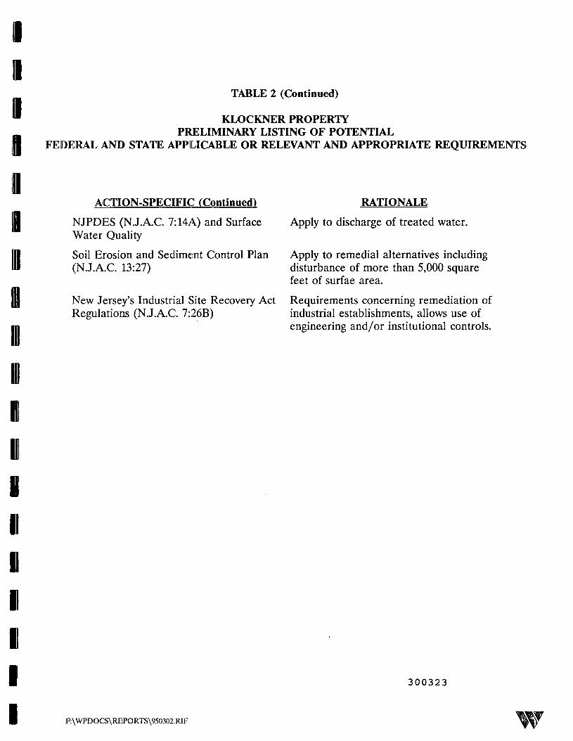
11
uI
III1111I
TABLE 2 (Continued)
* KLOCKNER PROPERTYPRELIMINARY LISTING OF POTENTIAL
II FEDERAL AND STATE APPLICABLE OR RELEVANT AND APPROPRIATE REQUIREMENTS
ACTION-SPECIFIC (Continued) RATIONALE
NJPDES (N.J.A.C. 7:14A) and Surface Apply to discharge of treated water.Water Quality
Soil Erosion and Sediment Control Plan Apply to remedial alternatives including(N.J.A.C. 13:27) disturbance of more than 5,000 square
feet of surfae area.
New Jersey's Industrial Site Recovery Act Requirements concerning remediation ofRegulations (N.J.A.C. 7:26B) industrial establishments, allows use of
engineering and/or institutional controls.
300323
F:\WPDOCS\REPORTS\950302.RIF

IllIIIIIininininininiiii
iiiiii
nii
TABLE 2 (continued)
KLOCKNER PROPERTYPRELIMINARY LISTING OF POTENTIAL
FEDERAL AND STATE APPLICABLE OR RELEVANT AND APPROPRIATE REQUIREMENTS
CONTAMINANT-SPECIFIC
Safe Drinking Water Act
Health Advisories, EPA Office ofDrinking Water
Clean Water Act (PL92-500); FederalWater Quality Criteria (FWQC)
Clean Air Act (42 USC 7401); NationalAmbient Air Quality Standards (NAAQS)for six criteria pollutants (40 CFR Part50)
Water Quality Regulations Title 6,Chapter X, Parts 700-705
Ground Water Classifications, QualityStandards and Effluent Standards and/orLimitations (N.J.A.C. 7:9-6)
Classes and quality standards forground water
Effluent standards and/or limitationsfor discharge to ground water
NJDEP Soil Cleanup Objectives
Surface Water Standards and Criteria
RATIONALE
Remedial actions may provide clean up tothe Maximum Contaminant Levels(MCLs)
Maximum Contaminant Level Goals(MCLGs) are promulgated Federalcriteria and include VOCs
RI activities identified presence ofchemicals for which health advisories arelisted
Contamination pattern or remedialalternative may include discharge tosurface waters
Remedial alternatives may includevolatilization technologies
Provides surface water and groundwaterclassifications and standards
Remedial action may require cleanup tostate standards if they are more stringentthan federal
State of New Jersey requires protection ofground water for use as potable water andcleanup to these standards.
Remedial alternatives may impact groundwater on site.
Remedial alternatives may address soiltreatment.
Remedial alternatives may impact surfacewater.
300324
F:\WPDOCS\REPORTS\950302.RIF
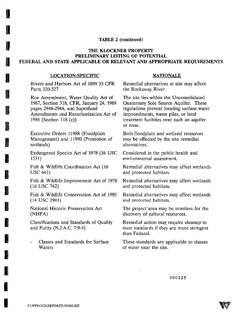
0
TABLE 2 (continued)
THE KLOCKNER PROPERTYPRELIMINARY LISTING OF POTENTIAL
FEDERAL AND STATE APPLICABLE OR RELEVANT AND APPROPRIATE REQUIREMENTS
ill
IBIII
IIBIID1P1I1
LOCATION-SPECIFIC
Rivers and Harbors Act of 1899 33 CFRParts 320-327
Roe Amendment, Water Quality Act of1987, Section 318, CFR, January 24, 1989pages 2946-2948, and SuperfundAmendments and Reauthorization Act of1986 (Section 118 (c))
Executive Orders 11988 (FloodplainManagement) and 11990 (Protection ofwetlands)
Endangered Species Act of 1978 (16 USC1531)
Fish & Wildlife Coordination Act (16USC 661)
Fish & Wildlife Improvement Act of 1978(16 USC 742)
Fish & Wildlife Conservation Act of 1980(14 USC 2901)
National Historic Preservation Act(NHPA)
Classifications and Standards of Qualityand Purity (N.J.A.C. 7:9-4)
Classes and Standards for SurfaceWaters
RATIONALE
Remedial alternatives at site may affectthe Rockaway River
The site lies within the UnconsolidatedQuaternary Sole Source Aquifer. Theseregulations prevent locating surface waterimpoundments, waste piles, or landtreatment facilities over such an aquiferor zone.
Both floodplain and wetland resourcesmay be affected by the site remedialalternatives.
Considered in the public health andenvironmental assessment.
Remedial alternatives may affect wetlandsand protected habitats.
Remedial alternatives may affect wetlandsand protected habitats.
Remedial alternatives may affect wetlandsand protected habitats.
The project area may be sensitive for thediscovery of cultural resources.
Remedial action may require cleanup tostate standards if they are more stringentthan Federal.
These standards are applicable to classesof water near the site.
300325
F:\WPDOCS\REPORTS\950302.RIF

TABLE 3A
KLOCKNER PROPERTYSUMMARY OF PROPOSED SOIL GAS SAMPLES
III
III
in
AreaAlleyway AreaBuilding 12
II
II
Soil Gas SampleDesignation
SGA-04ASGA-13SGA-14
SGA-14ASGA-15SGA-21SGA-22SGA-23SGA-24SGA-25
SGA-3A1SGA-3A2SGA-33SGA-34SGA-35SGA-36SGA-43SGA-44SGA-45
SGA-4A6SGA-51SGA-52SGA-53SGA-54SGA-55SGA-63SGA-64SGA-65
AnalyticalParameters
PHALPHALPHALPHALPHALPHALPHALPHALPHALPHALPHALPHALPHALPHALPHALPHALPHALPHALPHALPHALPHALPHALPHALPHALPHALPHALPHALPHAL
300326
F:\WPDOCS\REPO RTS\950302.RIF

300327
nTABLE 3A (Continued)
KLOCKNER PROPERTYSUMMIARY OF PROPOSED SOIL GAS SAMPLES
III
ID
I11Iiiiii
AreaNorth Drum StorageArea - Building 12
Soil Gas Survey -Building 13
Soil Gas SampleDesignation
SGN-11SGN-12SGN-13SGN-20SGN-21SGN-22SGN-23SGN-31SGN-32SGN-33SGN-42SGN-43
SG-OOASG-01ASG-10SG-11SG-12
SG-12ASG-13SG-14SG-15SG-20
SG-20ASG-21
SG-22ASG-23SG-24SG-25SG-30SG-31
SG-32ASG-32BSG-33SG-34
AnalyticalParameters
VOCVOCVOCVOCVOCVOCVOCVOCVOCVOCVOCVOC
PHALPHALPHALPHALPHALPHALPHALPHALPHALPHALPHALPHALPHALPHALPHALPHALPHALPHALPHALPHALPHALPHAL
F:\WPDOCS\REPORTS\950302.RIF w

TABLE 3A (Continued)
KLOCKNER PROPERTYSUMMARY OF PROPOSED SOIL GAS SAMPLES
Area
IDIIIIIIII
II
Soil Gas SampleDesignation
SG-35SG-40SG-41SG-42
SG-42ASG-42BSG-43SG-44SG-45SG-46SG-50
SG-50ASG-51SG-52
AnalyticalParameters
PHALPHALPHALPHALPHALPHALPHALPHALPHALPHALPHALPHALPHALPHAL
PHAL - Purgeable halocarbons by EPA Method SW-846 8010VOC - Volatile organic compounds by EPA Methods SW-846 8010 and SW846 8020
NOTE 1: Sample locations identified by grid row and column numbersNOTE 2: Samples will be analyzed in mobile laboratoryNOTE 3: Building 12 samples will be collected from depth of 3 feet and Building 13 at 4 feetNOTE 4: Additional soil gas samples will be collected at the Building 13 Property from two depths in
any potential source areas identified by the first phase of soil gas samples
II
II
300328
F:\WPDOCS\REPORTS\950302.RIF

IIII
TABLE 3B
KLOCKNER PROPERTYSUMMARY OF PROPOSED SOIL SAMPLING
B
'1inIIIIII1
1
111111
«1
AEC
Building 12
UndergroundGasoline Tank
Waste Oil Tank
Catch Basin/StormSewer
Leaching Pit
Degreaser Pit
Alleyway1
Scale Room
Drum Storage Shed
Drum Storage inAlleyway
North DrumStorage Area
SampleDesignation
SSGT-1
SSGT-2
SSWT-1SSWT-2
SSCB-1
SSLP-1
SSDP-1
SSAW-12
SSAW-22
SSAW-32
SSAW-42
SSAW-52
SSAW-62
SSAW-72
SSSR-1SSSR-2SSSR-3
SSFS-1ASSFS-1B
SSDSA-1
SSNDS-1ASSNDS-1BSSNDS-2ASSNDS-2B
SampleDepth
0-6" Below TankBackfill
0-6" Below TankBackfill
7-7.5'7-7.5'
2-2.5'
12-12.5'
3-3.5'
Field Determined0-6" below floor0-6" below floor
0-6" below pavementField Determined
0-6" below pavement
0-6" below pavementField Determined
0-6" below pavementField Determined
AnalyticalParameters
VOC
VOC
PHALPHAL
BN, TAL
TAL
PHAL
PHALPHALPHALPHALPHALPHALPHAL
PHALPHALPHAL
PHC, BN*, TALVOC
TAL, CN
PHC, BN*, TALVOC
PHC, BN*, TALVOC
I
1
Sump SSSP-1 1-1.5' below sumpinvert
PHC, VOC, BN*, TAL
300329
F:\WPDOCS\REPORTS\950302.RIF

'II
HI
Illin0iiIKill
II
II
1
1
1
KEY
PHCVOCBN
TALCNPHALGSTOC
i2
9
TABLE 3B (Continued)
KLOCKNER PROPERTYSUMMARY OF PROPOSED SOIL SAMPLING
AEC
Building 12
GeologicCharacterization
Building 13
GeologicalCharacterization
SampleDesignation
SSGC-1SSGC-2SSGC-3SSGC-4
SSGC-?
SampleDepth
Field DeterminedField DeterminedField DeterminedField Determined
Field Determined
AnalyticalParameters
GS, TOCGS, TOCGS, TOCGS, TOC
GS, TOC
- Petroleum Hydrocarbons by EPA Method 418.1 modified for soil- Target compound list Volatile Organic Compounds +10 by EPA Method SW-846 8240- Target compound list Base/Neutral Extractable Organic Compounds +15 by EPA Method SW-
846 8270- Total analyte list metals by EPA Methods SW-846 6010 and SW-846 7000- Cyanide by CLP SOW Methodology for Inorganic Analysis- Purgeable Halocarbons by EPA Method SW-846 8010- Grain size by ASTM D-422- Total Organic Carbon by USEPA Region II Lloyd Kahn MethodContingent on PHC resultsThis area includes the Quonset Hut and area between the Alleyway and Degreaser PitThe actual number of boring locations and samples collected from each boring location will bebased on the results of the proposed soil gas surveySample depths will be field determined, see 2
Number of samples to be determined by results of soil gas survey
300330
F:\WPDOCS\REPORTS\950302.RIF

TABLE 4
KLOCKNER PROPERTYSUMMARY OF PRESERVATION METHODS, SAMPLE CONTAINERS,
HOLDING TJMES AND ANALYTICAL METHODS
Parameter
A. Soil Sample Analysis
GC Purgeable Halocarbons
TCL Volatile Organic
Mercury
RGB's
Total Cyanide
Sample Container
4 oz. volatile organic analysisglass container
4 oz. volatile organic analysisCompounds +10 with Xylenes glass container
TCL Base/Neutral ExtractableOrganics +10
i OZ. yi333 COPuain
TAL Metals (except Mercury) 8 oz. glass container
8 oz. glass container
8 oz. glass container
8 oz. glass container
SampleVolume
5g
5g
19
30g
30g
Preservation
4°C
4°C
4"C
4°C
4°C
4«C
4°C
MaximumHolding Time*
14 days
14 days
Extraction: 14 daysAnalysis: 40 days fromextraction
6 months
38 days
Extraction: 14 daysAnalysis: 40 days fromextraction
14 days
300331
Analytical Methodology
SW-846, 3rd edition, vol. 1-B; GC-8010
SW-846, 3rd edition, vol. 1-B; GC/MS-8240
SW-848, 3rd edition, vol. 1-B; GC/MS-6270
SW-846, 3rd edition, vol. 1-A; 6010& 7000
SW-846, 3rd edition, vol.1-A; 6010& 7000
SW846, 3rd edition, vol. 1-B; GC-8080
CLP SOW Methodology, forInorganic Analysis Multi-Media, Multi-Concentration,Document ILM03.0
Petroleum Hydrocarbons
Grain Size
Total Organic Carbon
B. Soil Gas Analysis
GC Volatile Organics
8 oz. glass container
8 oz. glass container
30g
25g
Pre-evacuated 30 ml glass vial 30 ml @ 2 atm
4«C
4°C
Extraction: 28 daysAnalysis: 40 days fromextraction
28 days
5 days
* Holding time begins at time of sample collectionNote: Sample containers will be provided by laboratories and will be pre-cleaned and certified in accordance with EPA protocol.
EPA Method 418.1 modifiedfor soil
ASTM D-422
USEPA Region 2 LloydKahn Method fordetermination of TotalOrganic Carbon in Sediment,July 1988
SW-846 3rd edition, vol. 1-B; modified 8010 &8020
F:\WFDOCS\REPORTS\950301RIF

91
III
ID
TABLES
KLOCKNER PROPERTYREMEDIAL INVESTIGATION REPORT
TABLE OF CONTENTS
Section
EXECUTIVE SUMMARY
1. INTRODUCTION2. STUDY AREA INVESTIGATION3. PHYSICAL CHARACTERISTICS4. NATURE AND EXTENT OF CONTAMINATION5. CONTAMINANT FATE AND TRANSPORT6. RISK ASSESSMENT7. SUMMARY AND CONCLUSIONS
300332
F:\WPDOCS\REPORTS\950302.RIF
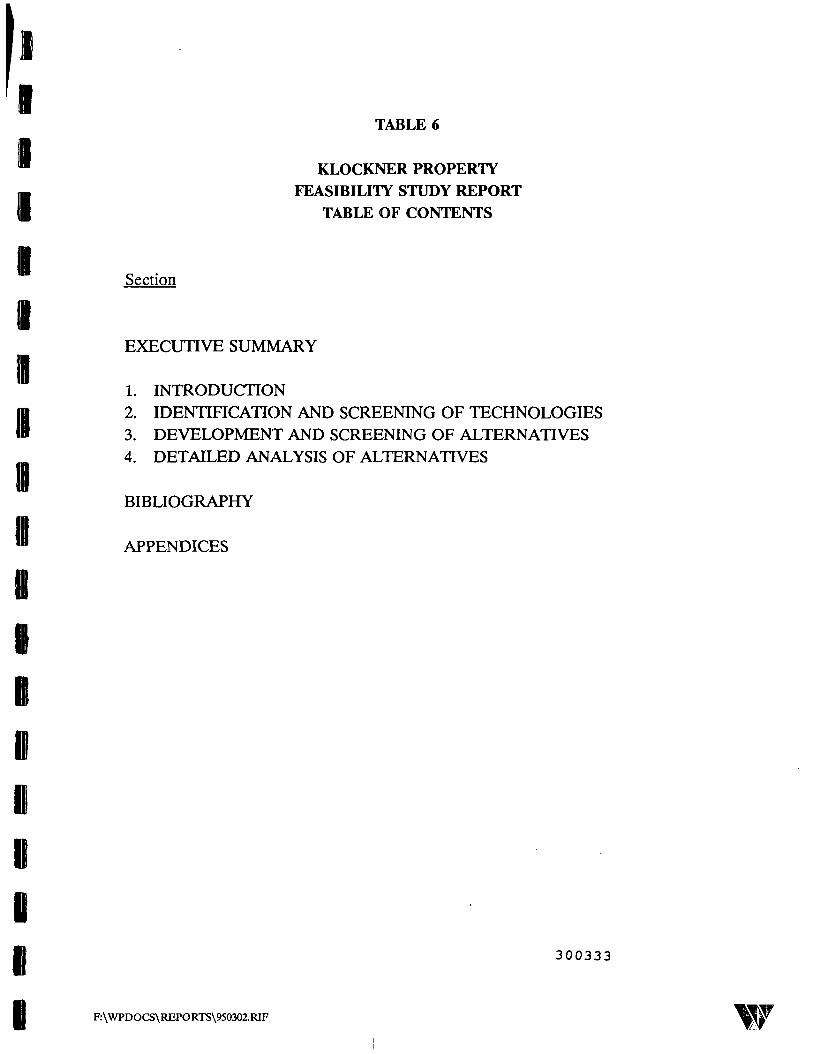
1I
11
DiII1
TABLE 6
KLOCKNER PROPERTY
FEASIBILITY STUDY REPORT
TABLE OF CONTENTS
Section
EXECUTIVE SUMMARY
1. INTRODUCTION2. IDENTIFICATION AND SCREENING OF TECHNOLOGIES3. DEVELOPMENT AND SCREENING OF ALTERNATIVES4. DETAILED ANALYSIS OF ALTERNATIVES
BIBLIOGRAPHY
APPENDICES
300333
F:\WPDOCS\REPORTS\950302.RIF

IiIeiiiijiiiieisiii
TABLE 7
KLOCKNER PROPERTYPROJECTED RI/FS SCHEDULE
1.0 TASK 1 - PROJECT PLANNING1.1 Draft Plans1 .2 AQoncy R0w6w1.3 Draft Rnal Plansi A MQOnCy MwnOW1.5 Draft Rnal Plans
2.0TASK2 - COMMUNITY RELATIONS <S>A)
3.0 TASKS - SITE CHARACTERIZATION3.1 Reid Investigation3.1.1 Procure Subcontractors3.1.2 Soil Gas Surveys3.1.3 Soil Sampling3.2 Data Analysis3.3 Data Management3.3.1 Sample Analysis33.2 Validation3.4 Monty Progress Reports3.5 Characterization Summary Report
4.0TASK4 - IDENTIFICATION OF CANDIDATETECHNOLOGIES FORTREATABUJTY STUDIES
5.0 TASKS - TREATABIUTY STUDIES
K n TAQk*ft Rl lf A^RF*yyUFKTT fffA\D.U 1 AO^O rUor\ AOOCOOWICI't 1 \cmf
7.0TASK7 - ffl REPORT7.1 Draft Rl Reportt .£. /\ysncy rwwsw7.3 Rnal Rl Report
6.0TASK8 - DEVELOPMENT OF RBHEOIAL ACTIONOBJECTIVES AND SCREENIMG OF REMEDIALALTERNATIVES8.1 Identification8.2 Initial Screening8.3 Technical Memo
9.0TASK9 - FS REPORT9.1 Detailed Analysis of Remedial Alternatives9.2 Draft FS Report9.3 Agency Review9.4 Rnal FS Report
March
'WMf&
April
' ^M
May
"# 1.1
$£$%$'&
x^^p
June
4.0
19July
?*jyy*yy,f*'i~y.
SSiSiSSS:
98Aug
WMMi
Sep
¥gxg 13
Oct Nov
4 A
Dec
^ 1-5
SgP&sijg
Jan
'$$$$j$&
Fab
WJxSxW:X*X"X'X-Xv
$n$m$
March
3.1.1
f
FXM,,*
April
3.1.2: 3.1.'
•sf,£i»':
,
May
; 331
-/ :
19June
3.2
"3.32
07July
igigg-gjj-jj
^3^
Aug
xJxSxSSxx5
Sep
;X g:¥<
Oct Nov
™¥?:§sx?
-4.0
-5.0
A n
iisss
Dec
'MMi
•Sgjg^J
Jan
gpwjfcxs
^x« 7-1
Feb
WWM
: |:g ¥:SS
8.1
March
|
|
•§§§:§:
7 O
W
82
April
W73
S.3
^^x^^
191May
W$i$&i&
S?SS91
S3June
$$$$$$
$Xi&
July
^ g-g:i
9.2
Aug Sep
SjSssis
§^^^?
Q ^
Oct
2.0
3.4
9.4
- - Projected period for agency review of documents and preparation of Risk Assessment* If task is necessary, schedule will be revised
NOTE; Schedule assumes EPA issues approval of RlfS Work Plan during January 1997
F:\USERS\LOTUS<e50302-1 300334

i
300335

Hi
inID
IK
ii
it§iiiiii
FIGURES
1.1 Site Location on USGS Dover Quadrangle1.2 Site Map of Klockner Property1.3 Rockaway Borough "Well Location Map2.1 Geologic and Hydrogeologic Cross Section2.2 Topography of Klockner & Klockner Property3.1 Site Map Building 123.2 Site Map Building 135.1 Proposed Soil Gas Survey - Building 125.2 Proposed Soil Sample Location - Building 125.3 Proposed Soil Gas Suivey - Building 13
300336
F:\WPDOCS\REPORTS\950302.RIF
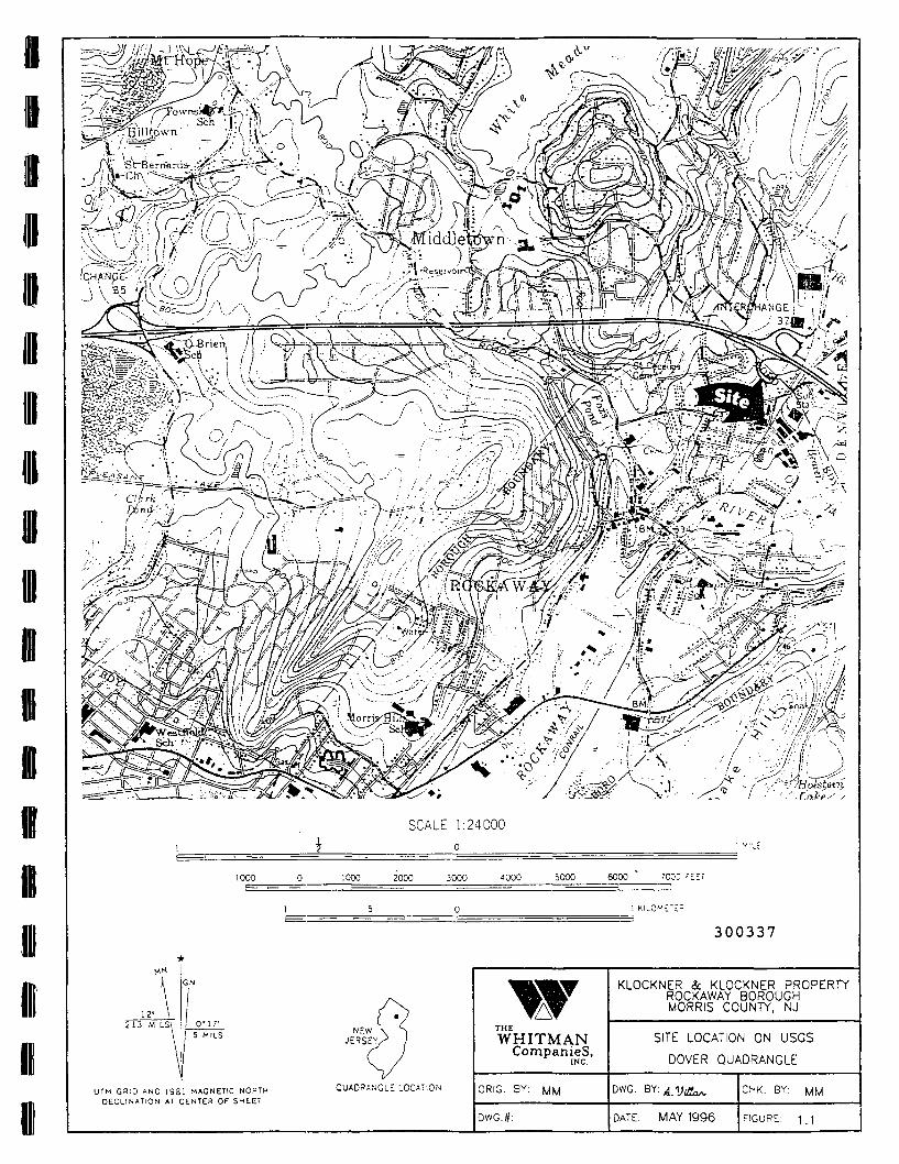
/ i &"• o \ <.if- • (; -\ . ° \
i ^^-T/;<riMBil xto '< f\r?" --•>. •^ -'' *'.• ) \ ~— -
--• / .*• / v_/ - ^^ ^^ _
SCALE 1:24000
1000 1000 2000 3000 4000 5000 6000 7CCO "t-T
300337
1 IGN
12-213 MILS\ I 0'17'
J 5 MILS
UTM GRID AND 1981 MAGNETIC NORTHDECLINATION AT CENTER OF SHEET
QUADRANGLE LOCATION
wWHITMAN
Companies,
ORIG. BY:
DWG.#:
KLOCKNER & KLOCKNER PROPERTYROCKAWAY BOROUGHMORRIS COUNTY, NJ
SITE LOCATION ON USGS
DOVER QUADRANGLE
DWG.
DATE: MAY 1996
CHK. BY: WM
FIGURE: 1.1

SOURCE:AERIAL SURVEY DATED JUNE 1994 PREPAREDBY ROBINSON AERIAL SURVEY'S INC. FORCONESTOGA-ROVERS & ASSOCIATES
300338
wTHEWHITMAN
Companies,
ORIG. BY: MM
DWG.#:
KLOCKNER & KLOCKNER PROPERTYROCKAWAY BOROUGHMORRIS COUNTY. NJ
SITE MAP OFKLOCKNER PROPERTY
DWG.
DATE: MAY 1996
CHK. BY:
FIGURE: 12

KLOCKNER <Sc KLOCKNER PROPERTYROCKAWAY BOROUGHMORRIS COUNTY, NJ
THEWHITMAN
Companies,ROCKAWAY BOROUGH WELL
LOCATION MAP
CHK. BY: MMORIG. BY: MM
SOURCE-. FIRST ENVIRONMENT DATE: MAY 1996
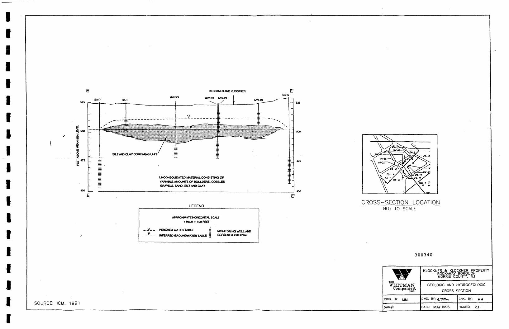
KLOCKNEH AND KLOCKNEH E'
52S i—SAJ-7 FO-1
MW-3OSAI-S
500
I475
45O
SILT AND OAY CONFIMNG UNIT
UNCONSOUDATED MATERIAL CONSISTING OF
VARIABLE AUOUKTB OF BOULDERS. COBBLESGRAVELS. SAND. SILT AND CLAY
525
500
475
450
E'
LEGEND
APPROXIMATE HORIZONTAL SCALE
1 INCH-100 FEET
PEBCHED WATER TABLE
INFERRED GftOONDWATER TABLE
UONTORING WELL ANDSCREENED INTERVAL
CROSS-SECTION LOCATIONNOT TO SCALE
300340
SOURCE: ICM. 1991
THE
WHITMANCompanies,
ORIG. BY:
DWG.#:
KLOCKNER & KLOCKNER PROPERTYROCKAWAY BOROUGHMORRIS COUNTY, NJ
GEOLOGIC AND HYDROGEOLOGIC
CROSS SECTION
DWG. BY:
DATE: MAY 1996
CHK. BY:
FIGURE: 2.1

SOURCE:AERIAL SURVEY DATED JUNE 1994 PREPAREDBY ROBINSON AERIAL SURVEY'S INC. FORCONESTOGA-ROVERS & ASSOCIATES
300341
THE
WHITMANCompanies,
ORIG. BY: MM
DWG.#:
KLOCKNER & KLOCKNER PROPERTYROCKAWAY BOROUGHMORRIS COUNTY, NJ
TOPOGRAPHY OF
KLOCKNER & KLOCKNER PROPERTY
DWG.
DATE: MAY 1996
CHK. BY:
FIGURE: 2.2

SANFTARY SEWERCONNECTION
OAK STREETT
1948AREA "C"
PROPERTY UNE
BUILDING #12
1946AREA "Ef
STORAGESHED
OFFICE AREA — CO CRETE
QUONSETHUTTANK 4
(1000 QfL)TANK 3
(1000 GAL)DEGREASER -u f 3
OPEN SOIL
FUNNEL
..-:•:•:•:•' APPROX. 1972RG!HMER-TMM
BOILER ROOMT/tNK 2
(5006 GAL)Rooy i AREA -cr i
ADDED 1978 1954AREA "A ASPHALT WALK
CONCRETEI I
LOADING DOCKic RAMPi
:•: PARKING AREA•:-. ASPHALT
1962/63AREA 'E*
SANITARY SEWER-• CONNECTION
FENCE it PROPERTYUNE
MH
GRASS it OPEN SOIL STORM SEWER
SANFTARY SEWER
NOTE: TANKS 1 THRU 5 HAVE BEEN REMOVED.
OPEN SOIL
GRASS/GRAVEL
TANK 1 (1000 GAL)
TANK 5 (550 GAL)
GRASS & OPEN SOIL
DFORMER 'LEACHING" PIT
300342
NOT TO SCALE
SOURCE: FIRST ENVIRONMENT
THE
WHITMANCompanies,
ORIG. BY:
DWG.#:
KLOCKNER & KLOCKNER PROPERTYROCKAWAY BOROUGHMORRIS COUNTY, NJ
SITE MAP BUILDING 12
DWG. BY:
DATE: MAY 1996
CHK. BY: MM
FIGURE: 3.1
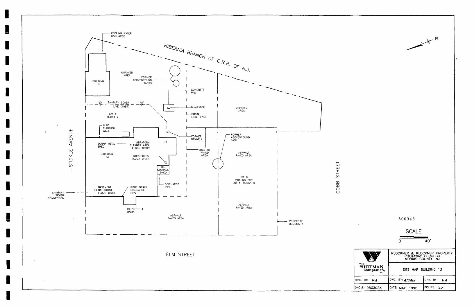
UJ1 =>
2UJ..<
UJ_li£oi—(j)
SANITARYSEWER
CONNECTION
DISCHARGE
{~r ^ " — - ****< *»--^^ 'A"CHOF(
r^"--^^~\ UNPAVED I J ! "-*-
AREA FORMER Y^ |BUILDING ABOVEGROUND \x~v 1
CONCRETE| PAD
CO SANITARY SEWER C-0
LINE (19871 \ [-, | DUMPSTEP
LOT 7 \ \ — -CHAINBLOCK 7 \ LINK FENCE
^ 1r P|PE i i
1 WALL j— | P^^ |I ' ' J. ^ . FORMER
, DRYWELL•~rRAP MFTAI VIBRATORY • O 1oCRAP METAL CLEANER AREA
FLOOR DRA,N L EDGE QF
RinmiNc | PAyrEO
,3 HYUKOPKLbS v 1 AREA
FLOOR DRAIN N. s~
OIL , \lSTORAGE 1 ^
SHED
^ '1 DISCHARGE '
BASEMENT r- ROOF DRAIN PIPEO BATHROOM / DISCHARGE |
FLOOR DRAIN / PIPE
CATCH DBASIN
ASPHALTPAVED AREA
ELM STREET
., N
:'^./? n
• °r N.j.
^^^^^^^
^^^ —
"^^--^
AREA
111 FORMER 1
/ TANK '/
/ ASPHALT
" j t D*/ UJ
Dd1 —
LOT 8 ^PARKING FOR
LOT 6. BLOCK 5 CDCD0o
PAVED AREA
| PROPERTY 3°°343
BOUNDARY
SCALE
0 40'
WW KLOCKNER & KLOCKNER PROPERTY' ROCKAWAY BOROUGH
MORRIS COUNTY. NJ
THE
Companies, SITE MAP BUILDING 13INC.
ORIG. BY: MM DW°- ^' A.VOa^ CHK. BY: MM
DWG.#: 950302X DATE: MAY. 1996 FIGURE: 3.2

\
\
• SGN-20
FENCE
\
\
> SGN-31
• SGN-42
• SGN-32
NORTH DRUM STORAGE AREA
' SGN-21 o SGN-22
• SGN-11 | SGN-12
.PROPERTYBOUNDARY
• SGN-43
.SGA-51
• SGA-3A1
• SGA-21
>SGN-33
'SGN-23
• SGN-13
o SGA-52
• SGA-3A2
>SGA-22
SGA-63 SGA-64 SGA-65
SGA-53 SGA-54
QUONSET HUT
SGA-43 SGA-44
•SGA-55
SGA-45
SGA-33
ALLEYWAY
• SGA-23
•SGA-34
•SGA-35
SGA-25SGA-24 •
•SGA-46
•SGA-36
FUNNEL
SGA-13
SCALE ROOM
• • •SGA-14 SGA-14A SGA-15
•SGA-04A
BUILDING
N
SGN-23
- PROPOSED SOIL GASSAMPLE LOCATION
- NORTHERN DRUM STORAGEAREA SAMPLE
SGA-23 - ALLEYWAY AREA SAMPLE
| GRID ROW LOCATION
SGA-3A4- GRID COLUMN LOCATION
I LOCATION OFF OF GRID
300344
WHITMANCompanies,
ORIG. BY: MM
DWG.#: 9503021
KLOCKNER & KLOCKNER PROPERTYROCKAWAY BOROUGHMORRIS COUNTY, NJ
PROPOSED SOIL GAS SURVEY
BUILDING 12
DWG. BY:
DATE: MAY 1996
CHK. BY:
FIGURE: 5.1

IIIIIIIIIIIIIIIIIII
BUILDING #12
FORMER STORAGESHED
QUONSET HUTTANK A (1000 GAU
DEGREASERPIT
TANK 3 (1000 GAU
DSA-1
T4NK 2(5006 GAL
IFORMER DRUM
STORAGENORTH DRUMSTORAGE AREA SR-1 ® FUNNEL,
SR-2 '
PARKING AREAASPHALT
ASPHALT I SHOULDER
FENCE <k PROPERTYUNE
MH
OPEN SOIL STORM SEWER
SANFTARY SEWER
STREET
NOTE: TANKS 1 THRU 5 HAVE BEEN REMOVED.
GRASS/GRAVEL
TANK 1 (1000 GAL)
TANK 5 (550 GAL)
DFORMER "LEACHING" PfT
LEGEND
CB - CATCH BASIN
SP-1 - SAMPLE DESIGNATION (TYPICAL)
• - PROPOSED SOIL SAMPLE LOCATION
O - POTENTIAL SOIL SAMPLE LOCATIONACTUAL LOCATIONS WILL BE BASEDON RESULTS OF SOIL GAS SURVEY
ALL SAMPLE LOCATIONS ARE SOIL SAMPLES.
THE
WHITMANCompanies,
ORIG. BY: MM
DWG.#:
KLOCKNER & KLOCKNER PROPERTYROCKAWAY BOROUGHMORRIS COUNTY. NJ
PROPOSED SOIL SAMPLE LOCATIONS
BUILDING 12
DWG. BY:
DATE: MAY. 1996
CHK. BY: MM
FIGURE: 52.

5SG-50
COOLING WATERDISCHARGE
UJ
Ld
OI—(/) 2
SANITARYSEWER
CONNECTION
2 3
ELM STREET
4 5
/ •SG-50A
1 I—
BUILDING14
SG-40CO SANITARY
LINE
LOT 7BLOCK 7
r— PIPESG-30 1 THROUGH
SG-20A»j
SHED
BUILDING13
SG-20
BASEMENTO BATHROOM
FLOOR DRAIN
SG-10 SG-11
SG-OOA
^ --^
SG-51 SG-52
UNPAVEDAREA FORMER
ABOVEGROUNDTANKS
SG-41
SEWER CO
(1987) ~\N
1 1
CLEANER AREAFLOOR DRAIN
HYDROPRESS —FLOOR DRAIN
SG-21
/
ROOF DRAINDISCHARGEPIPE
CATCH — -D *BASIN
' 'rjP'r\ .
^/A Q
- ^
^Q-SG-42A ^V)
SG-42
\ SG-32B
SG-32A i• • 1
P^^
O *
SG-22B
L
\j • SG-22A
OILSTORAGE
SHED
JSG-12A
1 DISCHARGEPIPE
i
SG-12
ASPHALTPAVED AREA
^ or ,(
CONCRETEPAD
SG-43
DUWPSTER
CHAINLINK FENCE
SG-33
FORMERDRYWELL
EDGE OFPAVED
nSG-23 V_
SG-13
-^
//
Kl>
"^^-T
SG-44
AREA
SG-34
r— FORMERABOVEGROUNDTANK
ASPHALT
SG-24
LOT 8PARKING FOR
LOT 6. BLOCK 5
PAVED AREA
" »
^^_
SG-45
SG-35
SG-25
SG-15
~~»»»
SG-46
PROBOU
UJUJce:f—CO
DQOo
LEGEND
< ; r m - PROPOSED SOIL GASSURVEY SAMPLE LOCATION
| - GRID ROW LOCATION
SG-32B— LOCATION OFF GRID
I - GRID COLUMN LOCATION
300346
THETyTT TTTuf A T^
Companies,
ORIG. BY: VIM
G.f: 950302X
KLOCKNER & KLOCKNER PROPERTYROCKAWAY BOROUGHMORRIS COUNTY, NJ
SOIL GAS SURVEY BUILDING 13
DWG- BY:
DATE: MAY. 1996
CHK. BY: MM
FIGURE: 5.3

300347

IllI
APPENDIX 1
FEBRUARY 1994 NJDEP SOIL CLEANUP CRITERIA GUIDELINES
IB
IIII'
300348
•I)III F:\WPDOCS\REPORTS\950302-RIF

Soli Cleanup Criteria (mg/kg)(Last Revised - 2/3/94)
300349
This listing represents the combination of Tables 3-1 and 7-1 from the Department of Environmental Protection andEnergy's February 3, 1992 proposed rule entitled Cleanup standards for Contaminated Sites/ N.J.A.C. 7:26D, withnoted corrections based upon errors identified by the Department during or subsequent to the comment period as wellas new toxicological information obtained since the rule proposal. Please refer to the respective footnotes for moredetail. Notwithstanding, where the following criteria are based' on human health impacts, the Department shall stillconsider environmental impacts when establishing site specific cleanup criteria. This along with other site specificfactors including background conditions may result in site specific cleanup criteria which differ from the criterialisted below. Therefore, this list shall not be assumed to represent approval by the Department of any remedialaction or to represent the Department's opinion that a site requires remediation.
Note: Material bracketed [thus] is deleted and material underlined thus is added
ContaminantAcenaphtheneAcetoneAcrylonitrileAldrinAnthraceneAntimonyArsenicBariumBenzene3,4-Benzofluoranthene (Benzo(b)fluoranthene)Benzo(a)anthraceneBenzo(a)pyrene (BaP)Benzo(k)fluorantheneBenzwl AlcoholBerylliumBis(2-chloroethyl) etherBis(2-chloroisopropyl) etherBis(2-ethylhexyl) phthalateBromodichloromethane (Dichlorobromomethane)BromoformBromomethane2-Butanone (MEK)Butylbenzyl phthalateCadmium
CASRN83-32-967-64-110.7-13-1309-00-2120-12-77440-36-07440-38-27440-39-371-43-2205-99-256-55-350-32-8207-08-9100-51-67440-41-7111-44-4
39638-32-9117-81-775-27-475-25-274-83-978-93-385-68-7
7440-43-9
ResidentialDirect ContactSoil CleanupCriteria(a) fb)
34001000(d)
10.040
10000(c)14(2(f)] 20(e)
70030.90.90.66(f )0.9
10000(c)1 ( f )0.66(f )
23004915] il(g)8679
1000{d)1100
1
NonResidential
Direct ContactSoil CleanupCrjteria(a) (b)10000(c)1000(d)
5 0.17
10000(c)340[2(f)J 20(e)
47000(n)13 .440.66(f )4
10000(c)
10000(c)210[22] 46(9)3701000(d)1000(d)
lOOOO(c)100
Impact toGround waterSoil CleanupCriteriafbl
100[50] 100(1)[100] JL(i)50
(500] 100 (i)
(h)(h)1
[500]-50010050050(h)[1]10100
111
50100(h)

Soil Cleanup Criteria (mg/kg)(Last Revised - 2/3/94)
Carbon tetrachlorida4"ChloroanilinaChlorobenzeneChloroform4-Chloro-3-methyl phenol (p-Chloro-m-creaol]Chloromethane2-ChlorophenolChryseneCopperCyanide4,4'-DDD (p,p'-TDE)
4, 4 '-DDTDibenz (a, h) anthraceneDtbromochlorome thane (Chi or odibromome thane)Di-n-butyl phthalateDi-n-octyl phthalate1, 2-Dichlorobenzene1, 3-Dichlorobenzene1, 4-Dichlorobenzene3,3' -Dichlorobenzidine1, 1-Dichloroethane1., 2-Dichloroethane1, 1-Dichloroethene1 , 2-Dtchloroethene1 , 2-Di"chloroethene
(trans)(cis)
2,4-Dichlorophenol1,2-Dichloropropane1,3-Dichloropropene (els and trans)DieldrinDiethyl phthalate2,4-Dimethyl phenolDimethyl phthalate2,4-DinitrophenolDinitrotoluene (2,4-/2,6- mixture)EndosulfanEndrinEthylbenzeneFluorantheneFluoreneHeptachlot:HexachlorobenzeneHexachlorobutadiene
56-23-5106-47-8108-90-767-66-359-50-774-87-395-57-8218-01-97440-50-857-12-572-54-872-55-950-29-353-70-3124-48-184-74-2117-84-095-50-1541-73-1106-46-791-94-175-34-3107-06-275-35-4156-60-5156-59-2120-83-278-87-5542-75-660-57-184-66-2105-67-9131-11-351-28-5
25321-14-6115-29-772-20-8
100-41-4206-44-086-73-776-44-8
118'-74-l87-68-3
2{k)230
~ 3719(k)
10009(c)5202809
600(m)1100
3220.66(f )
11057001100510051005702
57068
1000(d)791701040.042
10000(c)110010000(c)110
1(1)[3J 340(g)17
1000(d)23002300
0.150.66( f )
(H] Kg)
4(k)420068028(k)
10000(c)1000(d)520040600(m)
21000(0)12990.66(f )
1000(d)10000(c)10000(c)10000(c)10000(c)10000(c)
61000(d)241501000(d)1000(d)3100
435(k)0.18
10000(c)10000 (c)lOOOO(c)2100
4(1)[52) 6200(g)3101000(d)10000(c)10000(c)
0.652
[210] 21(g)
1(r)11
10010[50]500(h)(h)
[100][100](100)[500]
110010050100100100(1]1
1050[50]10(r)1'
505010501010(5050100[500]100(500](50)(50)
iO(j)
50(1)SOU)
500( i)100(3)
lO(i)
i(i-)
1)
iOO(i)
50(j)JLOO(i)100(9)
300350

Soil Cleanup Criteria (mg/kg)(Last Revised - 2/3/94)
HexachlorocyclopentadieneHexachloroefchaneIndeno(l ,2 ,3-cd)pyreneIsophoroneLeadLindane2-Methylphenol4-MethylphenolMethoxychlorMercury4-Methyl-2-pentanone(MIBK)Methylene chlorideNaphthaleneNickelNitrobenzeneN-NitrosodiphenylamineN-Nitrosodi-n-propylaminaPCBs (Polychlorinated biphenyls)PentachlorophenolPhenolPyreneSeleniumSilverStyrene1,1,1,2-Tetrachloroethane1,1,2,2-TetrachloroethaneTetrachloroethyleneThalliumTolueneToxaphene1,2,4-Trichlorobenzene1,1,1-Trichloroethane1,1,2-TrichloroethaneTrichloroethene (TCE)2,4,5-Trichlorophenol2,4,6-TrichlorophenolVanadiumVinyl chlorideXylenes (Total)Zinc
77-47-467-72-1193-39-578-59-1
7439-92-158-89-995-48-7106-44-572-43-5
7439-97-6108-10-175_no-291-20-3
7440-02-098-95-386-30-6621-64-71336-36-387-86-5103-95-2129-00-07782-49-27440-22-4100-42-5630-20-679-34-5127-18-47440-28-0108-88-3
8001-35-2120-82-171-53-6
1 79-00-579-01-695-95-488-06-2
7440-62-275-01-4
1330-29-77440-66-6
4006-0.9
1100100(p)
0.5*22800280028014
1000(d)49230250281400.66(f )0.496
10000(c)17006311023170344(k)2(f)
1000(d)0.10(k)682102223
5600623702
4101500(m)
73001004
10000(c)600(q)2.2
10000(c)10000(c)52002701000(d)21042002400(k)(n)5206000.66(f)224
10000{c)10000(c)3100{n)4100(n)9731070(k)6(k)2{f)
1000{d)0.2(k)
12001000(d)42054(k)
10000(c)2707100(n)
•71000(d)1500(m)
100100500(10) 50(j(h)(1) 5_0(j
[500] 5_0(i)(h)50[10] i(j)100(h)
[50] jLO(i)100
[1] 10(j)[100] 5_0(i)10050
[500] JLOO(J)(h)(h)
100111(h)
500 '[100] 5J)(i)1005011
50[50] 10(i)
300351
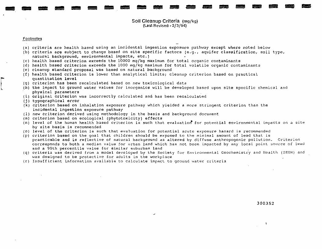
Soil Cleanup Criteria (mg/kg)(Last Revised - 2/3/94)
Footnotes
(a) criteria are health based using an incidental ingestion exposure pathway except where noted below(b) criteria are subject to change based on site specific factors (e.g., aquifer classification, soil type,
natural background, environmental impacts, etc.)(c) health based criterion exceeds the 10000 mg/kg maximum for total organic contaminants(d) health based criterion exceeds the 1000 mg/kg maximum for total volatile organic contaminants(e) cleanup standard proposal was based on natural background(f) health based criterion is lower than analytical limits; cleanup criterion based on practical
quantltation level(g) criterion has been recalculated based on new toxicological data(h) the impact to ground water values for inorganics will be developed based upon site specific chemical and
physical parameters(i) original criterion was incorrectly calculated and has been recalculated(j) typographical error(k) criterion based on inhalation exposure pathway which yielded a more stringent criterion than the
incidental ingestion exposure pathway(1) new criterion derived using methodology in the basis and background document(m) criterion based on ecological (phytotoxicity) effects(n) level of the human health based criterion is such that evaluation*1 for potential environmental impacts on a site
by site basis is recommended(o) level of the criterion is such that evaluation for potential acute exposure hazard is recommended(p) criterion based on the goal that children should be exposed to the minimal amount of lead that is
practicable and is reflective of natural background as altered by diffuse anthropogenic pollution. Criterioncorresponds to both a median value for urban land which has not been impacted by any local point source of leadand a 90th percentile value for similar suburban land
(q) criteria was derived from a model developed by the Society for Environmental Geochemistry and Health (SEGH) andwas designed to be protective for adults in the workplace
(r) Insufficient Information available to calculate impact to ground water criteria
300352