report on summer training by sayan roy
TRANSCRIPT

Report On Summer Training
At
Lube Blending Plant
Indian Oil Corporation Limited Paharpur
Project Guide: Mr. Pujan Kumar Maity, Dy. Plant Manager
Training period: 11 June, 2014 – 11 July, 2014
Submitted By
Sayan Roy
Department Of Mechanical Engineering (3rd
Year)
Future Institute of Engineering & Management
Kolkata

2
Sl.
No. Contents Page No.
1. Introduction 3
2. Map of the plant 4
3. Lubricant-Definition & Purpose 5 - 8
4. Classifications of lubricants 9 - 10
5. Process of the plant 11 -12
6. Base oil & Base oil storage tanks 13-15
7. Additive & additive storage tanks 16-17
8. Transfer Systems 17-20
9. Lube Blending & Blending Kettles 21-23
10. Inside blending kettle
Air Spanger
Agitator
Circulation
24-25
11. Boiler 26-27
12. Air Dryer 28-29
13. Lube Despatching Section
Barrel Filling
Manual Filling
Small can filling
30-34
14. Agro Spray section 35
15. Electra Plant (Transformer Oil) 36
16. Effluent Treatment Plant (ETP) 37-38
17. Quality Control Laboratory
Crackle test
Pour point test
Flash point test
Total Acid
Number(TAN)
39-42
18. Industrial Safety in Lube Blending Plant 43-51
19. Conclusion 52

3
INTRODUCTION The Lube Blending Plant of Indian Oil Corporation Limited
Location: Paharpur, Kolkata
Area: 13.59 acres
Production Capacity: 0.1 MMT/annum
Established on: 22nd March,1963
The Kolkata plant was commissioned in 1964.In 1973 the production of
‘SERVO’ lubricants started. In 1994, the plant was certified for ISO 9002:94
quality systems and in 2001, the plant was certified for ISO 14000:96
environment management systems. In 2003, SAP had been implemented in
Kolkata plant. In 2006, the plant has been certified for ISO 9001:2000.
More than 350 grades of lubricants are manufactured in this plant.
There are 28 base oil tanks having a total capacity of 30738 KL
There are 8 bulk additive tanks having a total capacity of 1365 KL
There are 14 blending kettles having a total capacity of 1712 KL
There are 2 diesel generator of 250 KVA and 350 KVA
2 Boilers of capacity 5 tons per hour
High capacity Effluent Treatment Plant (100KL &150 KL)
Integration of plant activities with all marketing network across the
organisation through SAP
Access control system is implemented in the plant
Quality Control laboratory which is equipped with instruments of latest
state of the art technology

4
Map of the Plant
Fig: Overview of the Lube Blending Plant, IOCL, Paharpur, Kolkata

5
Lubricant: Definition & Purpose
A lubricant is a substance introduced to reduce friction between moving
surfaces. It may also have the function of transporting foreign particles. The
property of reducing friction is known as lubricity (Slipperiness).
A good lubricant possesses the following characteristics:
High boiling point
Low freezing point
High viscosity index
Thermal stability
Hydraulic Stability
Demulsibility
Corrosion prevention
High resistance to oxidation
One of the single largest applications for lubricants, in the form of motor oil,
is protecting the internal combustion engines in motor vehicles and powered
equipment.
Typically lubricants contain 90% base oil (most often petroleum fractions,
called mineral oils) and less than 10% additives. Vegetable oils or synthetic
liquids such as hydrogenated polyolefin, esters, silicones, fluorocarbons and
many others are sometimes used as base oils. Additives deliver reduced
friction and wear, increased viscosity, improved viscosity index, resistance to
corrosion and oxidation, aging or contamination, etc.
Lubricants such as 2-cycle oil are added to fuels like gasoline which has low
lubricity. Sulphur impurities in fuels also provide some lubrication properties,
which have to be taken in account when switching to a low-sulphur diesel;
biodiesel is a popular diesel fuel additive providing additional lubricity.

6
Non-liquid lubricants include grease, powders (dry graphite, PTFE,
Molybdenum disulphide, tungsten disulphide, etc.), PTFE tape used in
plumbing, air cushion and others. Dry lubricants such as graphite,
molybdenum disulphide and tungsten disulphide also offer lubrication at
temperatures (up to 350 °C) higher than liquid and oil-based lubricants are
able to operate. Limited interest has been shown in low friction properties of
compacted oxide glaze layers formed at several hundred degrees Celsius in
metallic sliding systems, however, practical use is still many years away due to
their physically unstable nature.
Another approach to reducing friction and wear is to use bearings such as ball
bearings, roller bearings or air bearings, which in turn require internal
lubrication themselves, or to use sound, in the case of acoustic lubrication.
Purpose of Lubricant:
Lubricants perform the following key functions.
• Keep moving parts apart
• Reduce friction
• Transfer heat
• Carry away contaminants & debris
• Transmit power
• Protect against wear
• Prevent corrosion
• Seal for gases
• Stop the risk of smoke and fire of objects
• Prevent rust
Keep moving parts apart:
Lubricants are typically used to separate moving parts in a system. This has the
benefit of reducing friction and surface fatigue, together with reduced heat
generation, operating noise and vibrations. Lubricants achieve this by several

7
ways. The most common is by forming a physical barrier i.e., a thin layer of
lubricant separates the moving parts. This is analogous to hydroplaning, the
loss of friction observed when a car tire is separated from the road surface by
moving through standing water. This is termed hydrodynamic lubrication. In
cases of high surface pressures or temperatures, the fluid film is much thinner
and some of the forces are transmitted between the surfaces through the
lubricant.
Reduce friction:
Typically the lubricant-to-surface friction is much less than surface-to-surface
friction in a system without any lubrication. Thus use of a lubricant reduces
the overall system friction. Reduced friction has the benefit of reducing heat
generation and reduced formation of wear particles as well as improved
efficiency. Lubricants may contain additives known as friction modifiers that
chemically bind to metal surfaces to reduce surface friction even when there is
insufficient bulk lubricant present for hydrodynamic lubrication, e.g.
protecting the valve train in a car engine at start up.
Transfer heat:
Both gas and liquid lubricants can transfer heat. However, liquid lubricants are
much more effective on account of their high specific heat capacity. Typically
the liquid lubricant is constantly circulated to and from a cooler part of the
system, although lubricants may be used to warm as well as to cool when a
regulated temperature is required. This circulating flow also determines the
amount of heat that is carried away in any given unit of time. High flow
systems can carry away a lot of heat and have the additional benefit of
reducing the thermal stress on the lubricant. Thus lower cost liquid lubricants
may be used. The primary drawback is that high flows typically require larger
sumps and bigger cooling units. Turbochargers get red hot during operation
and the oil that is cooling them only survives as its residence time in the
system is very short i.e. high flow rate. If the system is shut down suddenly
(pulling into a service area after a high speed drive and stopping the engine)
the oil that is in the turbo charger immediately oxidizes and will clog the oil
ways with deposits.

8
Carry away contaminants and debris:
Lubricant circulation systems have the benefit of carrying away internally
generated debris and external contaminants that get introduced into the
system to a filter where they can be removed. Lubricants for machines that
regularly generate debris or contaminants such as automotive engines typically
contain detergent and dispersant additives to assist in debris and contaminant
transport to the filter and removal. Over time the filter will get clogged and
require cleaning or replacement, hence the recommendation to change a car's
oil filter at the same time as changing the oil. In closed systems such as gear
boxes the filter may be supplemented by a magnet to attract any iron fines that
get created.
Transmit power:
Lubricants known as hydraulic fluid are used as the working fluid in
hydrostatic power transmission. Hydraulic fluids comprise a large portion of
all lubricants produced in the world. The automatic transmission's torque
converter is another important application for power transmission with
lubricants.
Protect against wear:
Lubricants prevent wear by keeping the moving parts apart. Lubricants may
also contain anti-wear or extreme pressure additives to boost their
performance against wear and fatigue.
Prevent corrosion. Good quality lubricants are typically formulated with
additives that form chemical bonds with surfaces, or exclude moisture, to
prevent corrosion and rust.

9
Classification of Lubricant
The main types of lubricants are:
Automotive
Industrial
Specialty
Marine
Automotive Lubricants:
4 Stroke Engine Oil
2 Stroke Engine Oil
Multi-grade Engine Oil
Multi-grade Grease Oil
Transmission Fluid
Gas Engine Oil
Rail Road Oil
Industrial Lubricants:
Turbine Oil
System & Hydraulic System Oil
Knitting & Textile Oil
Circulating Oil
Vacuum Pump Oil
Steam Cylinder Oil
Heat Transfer Oil
Bearing Oil
Asphaltic Oil
Axle Oil
Gear Compound Oil etc.

10
Metal Working & Specialty Lubricants:
Soluble Cutting Oil
Neat Cutting Oil
Honing Oil
Aluminium Rolling Oil
Steel Rolling Oil
Quenching Oil
Rust Preventing Oil
Rubber Processing Oil
Agricultural Spray Oil
Glass Mould Oil etc.
Marine Lubricants:
Marine Crankshaft Oil
Marine Gear Oil
Marine Turbine Oil
Stern Tube Oil

11
Process of the plant
DISPATCHED TO REQUIRED LOCATIONS
BARGE/TANKER TRUCK WITH ADDITIVE BARREL
ADDITIVE STORAGE TANKS BASE OIL STORAGE TANKS
THROUGH MOTORS AND PUMPS
BLENDING KETTLE
TANK LORRY FILLING
SMALL CAN FILLING
BARREL FILLING
AGRO OIL BLENDING KETTLE
AGRO SPRAY
IN HDP CONTAINER
AND BUCKET
(1/5/6/7.5/10/12/20
LITRES)
BARREL (210 LITRES) TANK LORRY (2000) LITRES)

12
The base oil, also known as raw oil used for manufacturing
lubricating oil, is stored into the various storage tanks meant for
them. The base oil is brought by the tankers via sea route.
The oil is transferred to storage tanks by pipelines. The additives
which are to be mixed are brought by tank Lorries. Since the
amount of additive to be mixed to make a grade is quite small,
therefore the number of storage tanks for additives is much
smaller than the number of storage tanks. The additives and base
oil are stored in their respective storage tanks.
While making a specific grade of lubricating oil, certain amount
of base oil and additives are taken into the blending kettle. There
both are mixed by various pre-determined processes to
manufacture that specific grade of lube oil.
Now the manufactured lube oil is sent to three departments for
packaging namely small can filling, barrel filling and tank lorry
filling. In small can filling the lube oil is filled in small packages
with quantities varying from 1 to 20 litters. In barrel filing the oil
is packaged into a much larger quantity namely 210 litters. A
barrel is a large container which can contain 210 litters of oil. For
large scale dispatch tank lorry filling is used. A tank lorry with
large capacity is filled with the lube oil and dispatched to the
desired location.
In the whole process, the quality control department keeps an
eye on the quality of the oil which is dispatched. Even before the
manufacture of the lubricating oil, the quality control lab keeps a
tab on various important parameters of the oil.
The maintenance of all the machines in the plant is overseen by
the maintenance department. The maintenance department is
also responsible for overlooking the electrical system of the plant.
The finance department is responsible for allocating funds to
various vendors and repair works to be undertaken in the plant.
There is also a security department which monitors the security
in the plant. The fire security also comes under it and all the
proper equipment are kept in place.
13
Base Oil & Base Oil Storage Tanks The base oil, also known as raw oil used for manufacturing lubricating oil. The
main sources of base oil are Haldia Refinery, HPC, CRL and the rest are mainly
imported. The main types of base oil used in the plant are TOBH / TOBL /
HVI SP / LN / IN/ 500 SN HN/BN/BP/BITUMEN/PIB/PAO etc.
Mineral oil term is used to encompass lubricating base oil derived from crude oil.
The American Petroleum Institute (API) designates several types of lubricant
base oil:
Group I – Saturates <90% and/or sulphur >0.03%, and Society of
Automotive Engineers (SAE) viscosity index (VI) of 80 to 120
Manufactured by solvent extraction, solvent or catalytic dewaxing, and
hydro-finishing processes. Common Group I base oil are 150SN (solvent
neutral), 500SN, and 150BS (bright stock)
Group II – Saturates over 90% and sulphur under 0.03%, and SAE
viscosity index of 80 to 120
Manufactured by hydrocracking and solvent or catalytic dewaxing
processes. Group II base oil has superior anti-oxidation properties since
virtually all hydrocarbon molecules are saturated. It has water-white colour.
Group III – Saturates > 90%, sulphur <0.03%, and SAE viscosity
index over 120
Manufactured by special processes such as isohydromerization. Can be
manufactured from base oil or slag wax from dewaxing process.
Group IV – Polyalphaolefin (PAO)
Group V – All others not included above such as naphthenic, PAG,
esters.
In North America, Groups III, IV and V are now described as synthetic
lubricants, with group III frequently described as synthesised
hydrocarbons, or SHCs. In Europe, only Groups IV and V may be classed
as synthetics.
The lubricant industry commonly extends this group terminology to
include:
Group I+ with a Viscosity Index of 103–108
Group II+ with a Viscosity Index of 113–119

14
Group III+ with a Viscosity Index of at least 140
Can also be classified into three categories depending on the prevailing
compositions:
Paraffinic
Naphthenic
Aromatic
Lubricants for internal combustion engines contain additives to reduce
oxidation and improve lubrication. The main constituent of such lubricant
product is called the base oil, base stock. While it is advantageous to have a
high-grade base oil in a lubricant, proper selection of the lubricant additives
is equally as important. Thus some poorly selected formulation of PAO
lubricant may not last as long as more expensive formulation of Group III+
lubricant.
Currently there are 26 number of storage tanks in the plant which stores nearly
12000 KL of base oil as a whole. Storage tanks are large containers that hold
liquids or gases, in this case base oil. They work under very little or no pressure
which distinguishes them from pressure containers. These tanks are rounded in
shape, i.e. they are cylindrical in nature with either conical bottom or
hemispherical bottom. Every storage tank is equipped with heating facility.
Certain storage tanks are meant for a specific type of oil only. Oil cannot be
loaded in it, until the tank is washed three times.
The details of every storage tank with its capacity are given in the following:
STORAGE TANK CAPACITY (Litres)
1) S -1 1053488
2) S-2 1052859
3) S-3 590968
4) S-4 596715
5) S-5 1054022
6) S-6 1052685
7) S-7 264720
8) S-8 264950
9) S-9 265272
10) S-10 260263
11) S-11 262746

15
12) S-12 593059
13) S-15 1058264
14) S-16 1533231
15) S-17 1057465
16) S-18 1054337
17) S-19 1555729
18) S-20 2114736
19) S-21 2141021
20) S-22 2173390
21) S-23 250997
22) S-24 250990
23) S-25 3384459
24) S-26 3385108
25) S-27 3189609
26) S-28 3217977

16
Additives & Additives Storage Tanks
Additives are the other chemical ingredients of the Lubricant used with
proper proportions to produce desired effect. A large number of additives are used to impart performance characteristics to the
lubricants. The main families of additives are:
• Antioxidants
• Detergents
• Anti-wear
• Metal deactivators
• Corrosion inhibitors, Rust inhibitors
• Friction modifiers
• Extreme Pressure
• Anti-foaming agents
• Viscosity index improvers
• Demulsifying/Emulsifying
• Stickiness improver, provide adhesive property towards tool
surface (in metalworking)
• Complexing agent (in case of greases)
Note that many of the basic chemical compounds used as detergents (example:
calcium sulfonate) serve the purpose of the first seven items in the list as well.
Usually it is not economically or technically feasible to use a single do-it-all
additive compound. Oils for hypoid gear lubrication will contain high content of
EP additives. Grease lubricants may contain large amount of solid particle friction
modifiers, such as graphite, molybdenum sulphide.
Barrels filled with additives

17
Additives Storage Tanks
Additive oil storage tanks are also pretty much similar to base oil storage tanks.
There are 4 number of additive storage tanks in the plant. This is because the
quantity of additive required to make lubricants are very small. So as per their
requirement, their availability is also small. Some additives are also brought in
barrels (which is discussed later on). The following are the list of the additive
tanks and their capacity.
STORAGE TANK CAPACITY (In Litters)
1) A-5 251660
2) A-6 251345
3) A-7 251412
4) A-8 254680
Nearly all the additive storage tanks which are there in plant are of cylindrical type
with heating facility. Different types of additive which are kept in it are VI
improver, TBN, PIB (polyisobutylene) etc. All the tanks are located near new
filling centre.

18
Transfer Systems
The base oil and additives are stored in their respective tanks.
Then both type of oil are further transferred from storage tanks
to blending kettles. To make a certain grade of lubricating oil we
need base oil and additive in correct proportion as directed by
the Quality Control (QC) laboratory. Then both the oils are
mixed inside a blending kettle using various processes. The oil is
transferred with the help of pumps located in the blending
section. The pumps are controlled semi-automatically under the
keen observation of the persons sitting in the control room. Their
work in the section is to control the pumps through computer
system, better known as PLC.
Step 1: At first the base oil is brought from one storage tank to another
with the help of pumps. These pumps are controlled by motors. The
motors are also controlled semi-automatically. The manual part of the
process includes the attachment and detachment of pipes connecting
the pumps to various kettles. The automatic part includes the starting
of the motor. The process is that a desired quantity of base oil is to be
transferred from one tank to another. So the computer shows exactly
how much quantity of base oil should be transferred. The quantity is
fixed by the managers.
Step 2: After manually connecting the pipe to the desired output pipe
of the tank, the motor is started by the person sitting in the control
room. The weight of the base oil is shown by the unit Kg. During the
transfer process when a certain amount of oil is left to be transferred,
the system alerts the person in the control room. For example, when
600kg of oil is left to be transferred then the first siren is buzzed. The
second siren is buzzed when around 300Kg is left to be transferred.
Then the motor automatically stops after the second siren.

19
Step 3: The oil which remains stuck in the pipeline is transferred with
the help of air. Another valve is manually opened in the pipeline from
which the compressed air is supposed to pass. This air pushes the
remaining oil in the pipeline into the desired tank. A certain tolerance
is allowed regarding the quantity which is transferred. Not only base oil
but additives are also transferred using this technique.
If the additive to be transferred is very viscous, then more force
would be required to transfer it. If the force required exceeds the
force provided by the pumps, then the oil could get stuck in the
mechanism or it would take a great effort for the pump to transfer
it which means more wear and tear of the motor and the pump as
well as the pipelines. To solve this problem the additive is mixed
with a little amount of base oil to make it less viscous and easy to
flow. This does not affect the product as the mixing here is
compensated at the time of manufacturing the lubricant.
At the time when more than one type of base oil is to be
transferred, the process is extended a bit further. After the
transfer of one type of base oil is done another type of base oil is
transferred into the same tank. Since different base oils are of
different densities, therefore both the base oils floats above the
other in the tank.
Pipes through which the oil is transferred from storage tanks to blending kettles.

20
The Pumps connected at suction through storage tank and delivery to blending kettles

21
Lube Blending & Blending Kettles
The physical mixing process of blending components of a
lubricant to create a final product is called Lube Blending.
Lube oil blending and additive mixing is a fully automatic batching
process performed within four parallel lines each consisting of one
blender and one weigh hopper. Keeping the weight ratios of the lube
oil components is ensured by their precise weighing and is program-
controlled by remote opening-closing of dedicated flap valves.
Fig: Process Flow Diagram
PROCESS FLOW
DIAGRAM
BASE OIL TANKS
BULK ADDITIVES
DIRECTLY CHARGED
INTO BLENDING
KETTLE
BARREL ADDITIVES
CHARGED INTO
SUMPS
STIRRER
SUMP
STREAM COILS
FOR HEATING
AIR SPIDER
FOR AIR
PURGING
H
E
A
T
I
N
G
A
N
D
A
I
R
P
U
R
G
I
N
G
PUMP
BULK LOADING SMALL CAN FILLING BARREL FILLING
TANK LORRY FILLING
AND DISPATCH
DIRECT DISPATCH STACKING AND
STORING FOR FUTURE
DISPATCH
STACKING AND
STORING FOR FUTURE
DISPATCH
DIRECT DISPATCH

22
The blending process is the most important process in the entire plant. This
process is divided into three parts-
Mixing
Heating
Air Purging
The conical container called blending kettle is used to blend the lube. The base oil
from the tanks are put into the kettle to be blended. The bulk additives are directly
charged into the sump from where it is taken to the kettle.
The kettle is lined by heating coils along the inner walls to heat its contents during
the process of blending. The mixing is mainly done in three ways-using the stirrer,
using a pump and using air.
Step 1: A stream of air is used for air purging
Step 2: the motorized stirrer is used to mechanically stir the mixture to make it
homogeneous
Step 3: Finally a pump is present outside at the bottom of the kettle to set up a
cycle where the lube is continuously brought out of the kettle through the discharge
point at the bottom and is pumped back into the kettle. Thus, setting up a cycle to
blend the lubricant. The temperature of the mixture is measured and maintained
using a temperature gauge.
The Paharpur plant is incorporated with manual blending process. But in most
of the modern lube blending plants, modern blending techniques is used. Some
of the key parts of the modern blending techniques are-
Blending Systems
Automatic Batch Blending
In-Line Blending
Simultaneous Metered Blending
Process Automation Systems
WinBlend System Seven
Compact Blend System
e-BLEND Controller
Transfer Systems
Drum Decanting
Piggable Systems

23
Blending Kettles
A blending kettle is a small conical container or tank where the
mixing of different grades of liquids is done in correct proportion to
obtain a desired product. In this plant, base oil and additive are
mixed inside the blending kettle in a predetermined proportion to
obtain different types of lubricating oils. Unlike a storage tank, a
blending kettle not only stores the product but is also the place of
various processes which are required to make the finished product.
In Paharpur plant, there are 23 blending kettles. Some of them have
been converted into blending kettles from storage tanks.
Kettle No. Capacity (in KL) Facilities
BT 1/2/8/9 33 Heat,Stir,Air Blow & Circulation
BT 3/4/7 15 Heat,Stir,Air Blow & Circulation
BT 10/11/17 12 Heat,Stir,Air Blow & Circulation
BT 18 25 Heat,Stir,Air Blow & Circulation
BT 5/6 60 Heat,Stir,Air Blow & Circulation
FP 3 50 Heat,Stir,Air Blow & Circulation
BT 12/13/14/15/16 65 Heat,Stir,Air Blow & Circulation
FP 1 130 Heat,Stir,Air Blow & Circulation
S 10/13/14 240 Heat,Stir,Air Blow & Circulation

24
Inside Blending Kettle
After the transfer of base oil and additive in the blending kettle there
are various processes involved in making the lubricating oil. First the oil
is checked for any moisture content. This is done in the quality control
laboratory. Moisture content of the oil is checked with the help of
crackle test.If the oil is found to have high moisture content, then it is
heated with the help of steam. Inside the blending kettles there are
tubes which coil around the inner surface of the kettle. Through these
tubes, hot steam is passed. This hot steam increases the temperature of
the oil and releases the moisture content. Thus the oil becomes free
from water content. In the whole process the steam never directly
comes in contact with the oil. Ever directly comes in contact with the
oil.
After de moisturizing the oil, it is mixed. Remember the base oil and
the additives are of different densities. So it needs to be mixed with one
another. The mixing of the oil is done in three ways:-
Air Spangler
Agitator.
Circulation.
The type of mixing which is to be chosen depends basically on:-
Dehydration
Viscosity
Temperature
Duration
AIR SPANGLER
In this process air is circulated inside the kettle for mixing the oils. Every tank is connected to a
pipe compressed air flows. When two base oils are to be mixed, then the valves of one such
pipe are opened to allow the compressed air to pass through the oil. Air is introduced in the
kettle through a line. The air is circulated inside the kettle as long as the oil doesn’t get mixed
completely. While the process is on it is not advisable for anyone to stay near the kettle as it
may throw off some amount of oil outside. Due to this drawback this process is seldom used
for mixing purpose. Also the efficiency of this process is very low. Therefore apart from this
method, two other methods are used.

25
AGITATOR
Inside the blending kettle there is a mechanical stirrer fitted in its centre. It consists of blades
analogues to the ceiling fan at our home. Now when the oil is required to be mixed this stirrer
is turned on. It rotates just like the ceiling fan inside the kettle. The motion of the stirrer creates
a whirlpool inside the kettle which helps the oil to get mixed. The stirrer is kept on rotating up
to a certain time after which it is stopped. The stirrer is rotated both clockwise and anti-
clockwise after a time delay.
CIRCULATION
This method is most widely used one. Here the unmixed oil is circulated in a circulating line.
After the transfer of base oil and additive in the kettle, the circulating line is opened by the
persons sitting in the control room through computer. As soon as the circulating line is opened,
the oil is released from downwards, moves up through the line and then re-enters the kettle
from upward. Thus the oil keeps on circulating through the pipe as long as it is not mixed. This
is the most efficient way of mixing the oils. For the implementation of this method, it requires a
separate line for circulation.
Fig: Blending Kettle-Line Diagram
26
BOILER
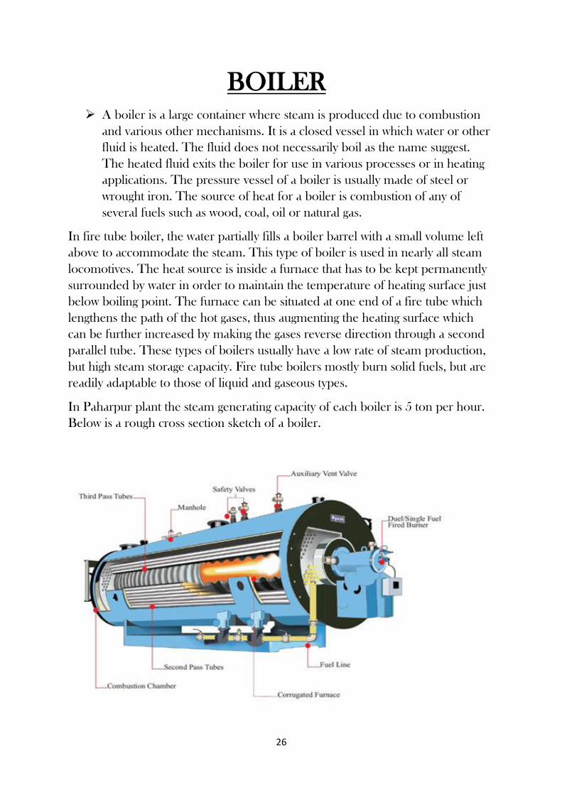
A boiler is a large container where steam is produced due to combustion
and various other mechanisms. It is a closed vessel in which water or other
fluid is heated. The fluid does not necessarily boil as the name suggest.
The heated fluid exits the boiler for use in various processes or in heating
applications. The pressure vessel of a boiler is usually made of steel or
wrought iron. The source of heat for a boiler is combustion of any of
several fuels such as wood, coal, oil or natural gas.
In fire tube boiler, the water partially fills a boiler barrel with a small volume left
above to accommodate the steam. This type of boiler is used in nearly all steam
locomotives. The heat source is inside a furnace that has to be kept permanently
surrounded by water in order to maintain the temperature of heating surface just
below boiling point. The furnace can be situated at one end of a fire tube which
lengthens the path of the hot gases, thus augmenting the heating surface which
can be further increased by making the gases reverse direction through a second
parallel tube. These types of boilers usually have a low rate of steam production,
but high steam storage capacity. Fire tube boilers mostly burn solid fuels, but are
readily adaptable to those of liquid and gaseous types.
In Paharpur plant the steam generating capacity of each boiler is 5 ton per hour.
Below is a rough cross section sketch of a boiler.

27
The process in the boiler is initiated by a force draft. The air is entered in the
combustion chamber through force draft. The heat is generated in the
combustion chamber inside. This is called 1st pass. The heated air is passed
through the air tubes, which are fitted inside. These tubes pass through the water
inside the boiler. The heated air is passed in the tube. Due to this, these tubes
gets heated up which heats up the water in turn. The water gets heated up without
directly coming in contact with water. This heated water produces steam, which is
passed through the steam outlet. This steam is then dried, with the help of air
dryer. The end product is then fed to various pneumatic equipment in the plant
which includes barrel filling machines, small can filling machines and other
equipment. The air which is produced after the combustion and which is used to
heat up the water, is then passed to a chimney which is then outlet to the
atmosphere. This is how steam is produced in the plant.
5 tonne Boiler

28
Air Dryer
A compressed air dryer is a device for removing water vapour from
compressed air. Compressed air dryers are commonly found in a wide
range of industrial and commercial facilities. The process of air
compression concentrates atmospheric contaminants, including water
vapour. This raises the dew point of the compressed air relative to free
atmospheric air and leads to condensation within pipes as the
compressed air cools downstream of the compressor.
a) Air Dryer b) Control Panel of Air Dryer
Excessive water in compressed air, in either the liquid or vapour phase,
can cause a variety of operational problems for users of compressed
air. These include freezing of outdoor air lines, corrosion in piping and

29
equipment, malfunctioning of pneumatic process control instruments,
fouling of processes and products and more.
There are various types of compressed air dryers. Their performance
characteristics are typically defined by the dew point. So, essentially
water vapour is removed from compressed air to prevent condensation
from occurring and to prevent moisture from interfering in sensitive
industrial processes.
30
Lube Despatching Section
The Lube Despatching Section is associated with FILLING of different
grades of Lubricants in mainly three ways-
Barrel Filling
Manual Filling
Bulk Filling
Small Can Filling
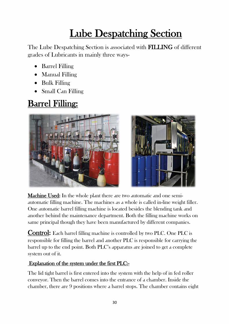
Barrel Filling:
Machine Used: In the whole plant there are two automatic and one semi-
automatic filling machine. The machines as a whole is called in-line weight filler.
One automatic barrel filling machine is located besides the blending tank and
another behind the maintenance department. Both the filling machine works on
same principal though they have been manufactured by different companies.
Control: Each barrel filling machine is controlled by two PLC. One PLC is
responsible for filling the barrel and another PLC is responsible for carrying the
barrel up to the end point. Both PLC’s apparatus are joined to get a complete
system out of it.
Explanation of the system under the first PLC:-
The lid tight barrel is first entered into the system with the help of in fed roller
conveyor. Then the barrel comes into the entrance of a chamber. Inside the
chamber, there are 9 positions where a barrel stops. The chamber contains eight

31
doors (so that any manual work can be done if any discrepancies occur in the
system).
1) At the first position the barrel is checked for any abnormalities in the entrance
only.
2) After checking the barrel is moved to the second position. Here the barrel is
synchronized in a certain position where filling could start. This happens as the
barrel comes to the position and is then slightly lifted up. Then it is rotated so as
to synchronize it in a perfect position, i.e. to find the mouth of the barrel.
3)At this position the seal of the barrel is opened and is carried to the 8th position
where it gets put on again.
4) Here the barrel comes to an empty position so as to wait for its turn to get filled
up.
5) The barrel is filled with the required graded oil. The amount of oil to be filled
is determined by weight that is entered in the control system. This weight is
determined by the people sitting in the control based on the oil’s density.
6) Same process occurs here as in 5th. Actually two barrels are filled at a time, so
filling is dedicatedly done at 5th and 6th positions simultaneously.
7) Then the barrel waits for its turn to get sealed.
8) Here the cap which was opened previously is carried up to this position and
fitted in the barrel appropriately.
9) At this position heat sealing is done using the Indian oil logo.
10) This position provides a final check for the barrel. After this position the
barrel comes out of the chamber and is carried to the end point of this part of
apparatus. In case a snag occurs inside the chamber, the problem is being shown
in the display control panel. Then the problem is addressed manually by opening
the concerned door which is provided in the chamber.
Explanation of the system under the second PLC:-
The filled barrel enters this system through roller conveyor. There is a sensor
fitted at the entrance which acknowledges their entry. Then the barrel comes to a
point where its movement is halted. At this point four barrels are collected. From
another side wooden pallets are dispatched. These pallets are kept in a place
inside the apparatus. The apparatus can hold maximum 7 pallets at a time. These
pallets are moved in the manner of FIFO (First In First Out). The lowermost
pallet is moved forward so that the filled barrels can be put on it. Then a metallic
plate is used to move the filled barrels on the pallets. Each pallet can have

32
maximum four barrels. Then these barrels are moved towards the desired truck
using fork lift (3-ton capacity).
Pallet side control panel:-
The control panel consists of one stop button, one restart button, an auto manual
rotating switch, two rotating switch to control the forks of the system (forks refers
to the rods that lifts the pallets inside the system). No one is allowed to go inside
the apparatus. In case someone enters the premises of the apparatus, the sensor
in place senses the movement and immediately the apparatus will be switched off
automatically. The switching off is indicated by the green glow of restart button
being off. The panel is restarted by pushing the restart button.
The whole system is controlled by sensors. On an average if all goes well, i.e. if
there are sufficient barrels and oil supply and no snag occurs in the machine, then
the system can generate up to 75 barrels/hour.
Manual Filling:
Machine Used: semi-automatic filling machine
named Avery.
Process: One person controls the whole system
out here. The weight of the oil to be filled is set
beforehand in the machine. Here opening and
closing of cap and sealing are done manually.
The capacity of this machine depends totally on the speed of manpower. Ideally
it is 45-50 barrels per hour. The semi-automatic system has been installed before
the automatic one. Its contribution to barrel dispatch might not match with the
automatic filling machines, but it acts as a booster for completion of barrel filling.
On a hectic day where demands of barrel filling are to be met urgently, this
machine helps a lot. The only drawback of this kind of filling machine is the use
of manpower and much lower rate of filling the barrels than the automatic ones.
The rate of production in this case completely depends on the speed of the
person operating the filling machine.
Bulk Filling:
In Bulk loading section there are 3 bays for loading 3 tank Lorries at a time.

33
Small Can Filling:
Small cans of quantities 1 litre to 20 litres is filled up here. Machines play a big
role in this section. Here manpower is used for mostly watch purpose. Small cans
of quantities 1, 5, 6, 7.5, 10, 12, 20 litres are manufactured. Out of this only 7.5
litre packaging is done manually. Apart from that, the process of all other
packaging is same. Let us see how packaging in small can filling is done.
Machine Used:
Semi-automatic 3-5 lt Filling Machine
Rotary filler 20 cans per minute
Induction Sealing Machine
Inkjet Printer
Cap Sealing Machine
Carton Sealing Machine
Automatic 3-5 lt Filling Machine
Rotary Filler 20 cans per minute
Automatic screw can mapping machine
Inkjet Printer
Induction Sealing Machine
Carton Sealing Machine
1 lt. Filling Machine:
80 caps per minute
Cap sealing machine
Inkjet printer
Induction sealing machine
Carton sealing machine

34
Process:
1) Firstly the required quantity of vessel is
brought, say of 5 litres.
2) Then the company stickering is done on the
box.
3) Then filling of lube oil is done in the can.
Actually the can is filled with 4.3 litres of oil.
The remaining weight accounts for the can
density. Also if a 5 litre can is filled with 5 litre of
oil then overflow might take place.
4) The can is then sealed with a cap. The caps which are used for sealing the cans are kept in a
separate section. From there the caps are brought to seal the cans.
5) After that, batch number, manufacturing date and price of the can are marked by air marker.
6) Then heat filling is done. There is a seal inside the cap. In this process the cap is heated and
the seal inside the cap if fitted in the bottle. This type of sealing can only be done by applying
heat to the cap.
7) The ready can then proceeds to a weight measuring instrument. Here the weight of the can
is measured. Now a certain tolerance is accepted in the weight. This means the weight of the
container can increase or decrease up to a certain limit. If it increases or decreases beyond that
limit then the container is punched out by a puncher.
8) After the container if checked, it is cartooned along with other containers and then
dispatched to the required location.
(All the above work is done electro pneumatically by the machines. Therefore compressed air
plays a big role in the functioning of the machines. However filling for the 7.5 litre is done semi
automatically. Here the process of filling oil in the container is done by pressing a push button.
The amount of oil which is to be filled is predetermined considering the container density and
overflow rate. The container is sealed manually by a person stationed at the end of the system.
Here also the container is marked by an air marker which shows its product number,
manufacturing date and MRP.)

35
AGRO SPRAY SECTION
This type of oil is used as a pesticide in certain agricultural purposes. This oil
cannot be used in all types of plantation. Its use is only restricted to tea gardens
and mango tree plantation. This may be regarded as one type of grade of lube oil.
It has a dedicated manufacturing facility in the small can section itself. This type
of oil is not manufactured round the year. It is only manufactured as per demand
of the customer. Small can filling section takes the amount of oil required from
storage tank. Then they transfer it to the buffer tank. This buffer tank is located
inside the small can filling. From the buffer tank oil is taken through pump and
filling is done. The amount of filling which is to be done is pre-set electronically.
SERVO Orchard Spray Oil:
This Oil is blended from high quality base stock especially for protection of
apple trees from San Jose scale. The oil is sprayed in the form of oil-in-water
emulsion on apple orchards during the months of December / January when the
ambient temperature is around 3 to 40C. The emulsion dissolves the waxy
protective shield of the insect and the oil film envelops it thereby killing the
insect by cutting off its air supply. It can be used for protection of eucalyptus,
cinchona etc. The oil does not have any toxic influence and is approved by Fruit
Research Station, Shalimar.
SERVO Rubber Spray Oil:
This Oil is a low viscosity product developed for use in rubber plantations. This
oil has an excellent solvency power with copper oxychloride for spray on rubber
plantations to combat the severe attack of fungus PHYTOPHTHORA which
leads to abnormal leaf fall affecting the vitality of the trees and resulting in loss of
latex yield. The mixture of oil and copper oxychloride is applied either by mini
micron sprayers or aerial spraying. The spreading characteristics of the oil enable
the copper particles to readily and uniformly distribute on the leaf surfaces and
leaf stalks and at the same time not permitting copper to be easily washed out. It
is approved by Rubber Research Institute of India, Kottayam.

36
ELECTRA PLANT
In Paharpur plant, transformer oil is manufactured separately in Electra Plant.
The transformer oil must not contain any moisture otherwise it causes dangerous
hazards to the transformer where it will be used. So the entire process is done
ensuring no water is present in the lubricant.
At first the mixture of additives and base oil are mixed in the
blending kettle by agitator, air purging and circulation, heat coils
under very high voltage.
Then the lubricant is taken to service tank to store the oil. From
there the oil is taken to Processing Unit which is skid mounted.
Here various type of filters under specified pressure refine the oil
and make it ready for final despatch.
In the barrel filling process, before filling the oil barrels are washed
with liquid nitrogen to make sure there is no moisture.
Electra Plant Setup

37
Effluent Treatment Plant (ETP)
As per pollution control board, no hazardous waste should not emit or
go out from a plant above some specified limit. In case of Lube
Blending Plant, the main hazardous waste is mixture of oil and water.
So there are 2 Effluent Treatment Plants (100/150KL) in the plant.
FIG: Effluent Treatment Plant
Many oils can be recovered from open water surfaces by
skimming devices. Considered a dependable and cheap way to
remove oil, grease and other hydrocarbons from water, oil
skimmers can sometimes achieve the desired level of water
purity. At other times, skimming is also a cost-efficient method to
remove most of the oil before using membrane filters and
chemical processes. Skimmers will prevent filters from blinding
prematurely and keep chemical costs down because there is less
oil to process.
Typically, the oil layer is skimmed off and subsequently re-
processed or disposed of, and the bottom sediment layer is
removed by a chain and flight scraper (or similar device) and a
sludge pump. The water layer is sent to further treatment
consisting usually of an electro-flotation module for additional
removal of any residual oil and then to some type of biological

38
treatment unit for removal of undesirable dissolved chemical
compounds.
Parallel plate separators are similar to API separators but they
include tilted parallel plate assemblies (also known as parallel
packs). The parallel plates provide more surface for suspended
oil droplets to coalesce into larger globules. Such separators still
depend upon the specific gravity between the suspended oil and
the water. However, the parallel plates enhance the degree of oil-
water separation. The result is that a parallel plate separator
requires significantly less space than a conventional API separator
to achieve the same degree of separation.
Here in Paharpur plant, the oily water separator is working under
three columns and a skimmer to get the useful oil from the waste
water. These columns are-
Primary Column : Coarse separating stage
Multimedia Filter : Suspended solid, dust particle separation
(Made of granular filtering material)
Coalescer Column : Micronics size oil particle separation
(Made of oleophilic material)
Primary Column Multimedia Filter Coalescer Column
Effluent treatment plant has the following components:
1. Air Compressor
2. Skimmer
3. Sump
4. Pump
5. Multimedia Filter
6. Butterfly Valves
7. Electro-Pneumatic Valves
The captured oil is taken to SLOP TANK for treatment and the rest
water is drained out to the environment.

39
Quality Control Laboratory The QC laboratory plays an important role in the plant. Here the oil is tested at
every stage before being used as a lubricant. The quality of base oil and additive is
tested here by various standard methods. The amount of base oil and additive
which is to be used to make a certain lubricant is also determined here. Then
required instructions are given to the control room to make that lubricant with
correct proportion of base oil and additive. The quality of base oil which is
received from the barge is scrutinized for moisture content with various tests such
as crackle test. Even the end product, i.e. the lubricant which is made is tested
before dispatching to its destination, is checked for quality and weight issues.
The lubricant oil contains approximately 90% of base oil and rest 10% additives
which are added to it. There are different types of base oil and they are presented
in terms of their viscosity. Indian oil produces the base oil of certain standard, i.e.
of certain fixed viscosities. If the customer desires the lubricant to be of certain
viscosity that isn’t standard viscosity, then different types of base oil are blended
to get the desired result. In QC lab three types of lubricant are made and tested:-
Automotive
Industrial
Specialty
The base oil and additive are mixed by heating and air circulation. The end result
is then tested for different properties like appearance, colour, flash point, pour
point, kinetic viscosity, viscosity index, foaming test, stability, Ca%, Zn%, Ph%,
base oil viscosity, emulsion test, rust test, TAN(total acid number), TBN(total
base number).

40
The different tests that are performed in QC lab are-
CRACKLE TEST:
The crackle test is a simple test to identify the presence of free and emulsified
water suspended in the oil, provided a few simple rules are followed.
a) Raise the hot plate temperature to 320°F (160°C). Always use the same
temperature.
b) Violently agitate oil sample to achieve homogenous suspension of water in
oil.
Using a clean dropper, place a drop of oil on the hot plate.
Observations:
a) If no crackling or vapor bubbles are produced after a few seconds, no free
or emulsified water is present.
b) If very small bubbles (0.5 mm) are produced but disappear quickly,
approximately 0.05 to 0.10 percent water is present.
c) If bubbles approximately 2 mm are produced, gather to the center of the
oil spot, enlarge to about 4 mm, then disappear, approximately 0.1 to 0.2
percent water is present.
d) For moisture levels above 0.2 percent, bubbles may start out about 2 to 3
mm then grow to 4 mm, with the process repeating once or twice. For even
higher moisture levels, violent bubbling and audible crackling may result.
e) Be wary of the presence of dissolved gases, fuel, refrigerants and volatile
solvents, which can cause false positives.
Limitations:
Although generally applicable, the crackle test does have some limitations:
a) The method is non-quantitative.
b) Hot plate temperatures above 320°F (160°C) induce rapid scintillation that
may be undetectable.
c) The method does not measure the presence of chemically dissolved water.
Safety:
Exercise extreme caution when performing the crackle test on oils that might
contain hazardous gases or low boiling point volatiles (such as ammonia
compressor oils), which might produce fumes and vapors that present inhalation
and/or serious skin or eye injury upon contact. When evaluating these oils, the
41
hot plate should remain under a vent hood that allows the analyst to conduct the
test without coming into contact with fumes or vapors.
a) Wear protective eyewear and long sleeves.
b) Perform test in a well-ventilated area.
POUR POINT TEST:
Procedure: The specimen is cooled inside a cooling bath to allow the formation
of paraffin wax crystals. At about 9 °C above the expected pour point, and for
every subsequent 3 °C, the test jar is removed and tilted to check for surface
movement. When the specimen does not flow when tilted, the jar is held
horizontally for 5 sec. If it does not flow, 3 °C is added to the corresponding
temperature and the result is the pour point temperature.
It is also useful to note that failure to flow at the pour point may also be due to
the effect of viscosity or the previous thermal history of the specimen. Therefore,
the pour point may give a misleading view of the handling properties of the oil.
Additional fluidity tests may also be undertaken. An approximate range of pour
point can be observed from the specimen's upper and lower pour point.
FLASH POINT TEST:
There are two basic types of flash point measurement - open cup and closed cup.
In open cup devices the sample is contained in an open cup which is heated, and
at intervals a flame is brought over the surface. The measured flash point will
actually vary with the height of the flame above the liquid surface, and at sufficient
height the measured flash point temperature will coincide with the fire point. The
best known example is the Cleveland open cup (COC).
There are two types of closed cup testers: non-equilibrium, such as Pensky-
Martens where the vapours above the liquid are not in temperature equilibrium
with the liquid, and equilibrium, such as Small Scale (commonly known as Seta
flash) where the vapours are deemed to be in temperature equilibrium with the
liquid. In both these types the cups are sealed with a lid through which the
ignition source can be introduced. Closed cup testers normally give lower values
for the flash point than open cup (typically 5–10 °C lower, or 9–18 °F lower) and

42
are a better approximation to the temperature at which the vapour pressure
reaches the lower flammable limit.
The flash point is an empirical measurement rather than a fundamental physical
parameter. The measured value will vary with equipment and test protocol
variations, including temperature ramp rate (in automated testers), time allowed
for the sample to equilibrate, sample volume and whether the sample is stirred.
TAN (Total acid number):
The total acid number (TAN) is a measurement of acidity that is determined by
the amount of potassium hydroxide in milligrams that is needed to neutralize the
acids in one gram of oil. It is an important quality measurement of crude oil. The
TAN value indicates to the crude oil refinery the potential of corrosion problems.
It is usually the naphthenic acids in the crude oil that causes corrosion problems.
This type of corrosion is referred to as naphthenic acid corrosion (NAC).
TAN value can be deduced by various methods, including
•Potentiometric titration: The sample is normally dissolved in toluene and
propanol with a little water and titrated with alcoholic potassium hydroxide (if
sample is acidic). A glass electrode and reference electrode is immersed in the
sample and connected to a voltmeter/potentiometer. The meter reading (in
millivolts) is plotted against the volume of titrant. The end point is taken at the
distinct inflection of the resulting titration curve corresponding to the basic buffer
solution.
•Colour indicating titration: An appropriate pH colour indicator e.g.
phenolphthalein, is used. Titrant is added to the sample by means of a burette.
The volume of titrant used to cause a permanent colour change in the sample is
recorded and used to calculate the TAN value.
Apart of these test many more tests are performed like the foaming test, rust test,
TBN etc. Thus QC laboratory is a vital part of paharpur plant as it helps in
maintaining the standard of the lubricants produced in the plan

43
Industrial Safety in Lube Blending Plant
An industrial safety is a countermeasure crucial in any hazardous plants
such as oil and gas plants. They are used to protect human, plant, and
environment in case the process goes beyond the control margins. As
the name suggests, these systems are not intended for controlling the
process itself but rather protection.
Industrial Safety can be provided through four ways-
Personal Protective Equipment (PPE)
Fire Safety
Security System
Safety from other hazards
Personal Protective Equipment:
Personal protective equipment (PPE) refers to protective clothing, helmets,
goggles, or other garments or equipment designed to protect the wearer's body
from injury. The hazards addressed by protective equipment include physical,
electrical, heat, chemicals, biohazards, and airborne particulate matter.
Protective equipment may be worn for job-related occupational safety and
health purposes, as well as for sports and other recreational activities. "Protective
clothing" is applied to traditional categories of clothing, and "protective gear"
applies to items such as pads, guards, shields, or masks, and others.

44
Head Protection:
Helmets are generally used for head protection. Different types of helmets are
used for different purposes. The helmets should have some standard properties
for industrial purpose. These are-
1) Temperature resistant
2) Strong & Durable
3) Rachet fit
4) Air Ventilation
5) Lightweight
6) Recyclable
Most of the helmets are made of HDPE, FRP, and ABS.
Examples of some helmets used in different industrial purposes-
Thermo-guard 9000 series, Vista 8000 Series, Ultra Vent 7000 Series, Helmet
Attachable Ear Muff etc.

45
Hand Protection:
Different types of gloves are used for hand protection in different industrial
purposes. Gloves are available to protect against:
Chemicals, contamination and infection (e.g. disposable latex/vinyl/nitrile
gloves)
Electricity, when voltage is too high
Extremes of temperature (e.g. oven gloves, welder's gloves)
Mechanical hazards (e.g. rigger gloves, chainmail gloves)
Mechanic gloves prime concern is to protect hands against mechanical type
of applications, where harsh elements of mechanical work is directly
detecting your hands required to be secured against the highest or lowest
levels of risks depending upon the working environment which is normally
measured in terms of different rating standards specifying the class of
gloves.
Hand safety concerns mechanical types of applications where the
involvement of highest and lowest level of risks
Lacerations and other wounds from sharp objects

46
Foot Protection:
Different types of cover shoes are available for foot protection. The
shoes should have these properties-
Different types of shoes are –
Ankle shoes
PVC shoes
Rock Master Gumboot
Edge Red Ex
Colin

47
Fall Protection:
There are different equipment for fall protection. Namely-
Anchor, body harness, connecting lines etc.
Anchor Body harness Connecting Lines

48
Fire Safety:
In common language, fire is burning of matter. In technical terms, fire is a chemical reaction
where matter reacts with oxygen under certain conditions to release heat and light energy. The
fire process can be considered as
Three conditions are essential component of any fire:
Fuel
Oxygen
Heat
Classification of fire:
Tank Fire
LPG Storage Vessel and Horton Spheres
TT Cargo Fires
Rail Tank Wagons
Electrical Machinery Fires
Pumps and Compressor Fires
Trench or Pit Fires
Sewer Fires
Spill Fires above Ground
Laboratory Fire

49
Fire Prevention:
The different processes for preventing fire are as follows-
Different Fire Extinguishers:

50
Security Systems:
Security system in the plant provides safety from any unwanted out-comers, any
terrorist attack, or any worker issues etc.
Security System is controlled by
Security Guards ( DGR )
Closed Circuit Cameras (CCTV)
Safety from other hazards: There are different types of hazards which should be prevented by
some safety measures.
In any case of lorry accidents or other transport problems,
authorisation faces different problems. These problems should be
prevented by proper training of the employees or by some other
means.
Sometimes oils are overflown from barrels, these problems (oil-
spillage) should be prevented to minimum level.
Suggestions on Safety Improvement

51
Though the basic safety procedure is well maintained in Paharpur plant, there are
some points to be highlighted to improve safety standard more firmly—
Though helmets are provided to each and every employees working in-field,
it is seen that some of them are not wearing it properly. This could bring
upon accidents. Therefore, the authority can take more strict action on this
issue.
The shoes that maximum employees are wearing are not safe according to
their line of work. Proper cover shoes should be provided by the authority
to ensure personal safety of each employee.
It is found that the blending kettles are not covered properly. This could be
dangerous for any employee. The blending kettles should be covered by
hard metallic cover or net.
The safety indicators (do’s and don’ts) should be in right place in the plant.
In case of very high noise generating regions, employees should wear ear
muffs.
Security system should be properly maintained and well skilled security
guards should be recruited to fight any emergency situation.
There are some very congested places in the plant (the blending kettle
platform, blending D etc.). There should be some modifications needed to
avoid any accidents in these regions.
Safety campaign must be carried out in a more regular basis so that the
employees can be cautious enough to fight any situation.
The firefighting equipment should be placed and in the right places.

52
Conclusion
I have gained knowledge by this training in various aspects as an
engineer, as I had first-hand experience in Indian Oil Corporation
limited. Training here, enhanced my cognition, as the employee has
explained, with commitment, all the doubts and question that arise in my
mind. This chance thrown at me, was a boon as I had only seen that real
about all the equipment seen in the industry, which now, I am able to
distinguish well enough. This was not possible with books knowledge. I
heartily thanks all employees of IOCL to have help me all throughout
my training.
I would like to express my gratitude to all those who gave me the
chance to complete this training. I want to thank the department of
training and development of IOCL, Eastern Region for giving me
permission to commence this training. It is really great opportunity for
me by which I had learned here many more of lube blending. I am
deeply indebted to Lube Blending Plant, Paharpur (Kolkata) for giving
such opportunity to students by which they complete their vocational
training which is the part of the course.