report gps yash
TRANSCRIPT
8/8/2019 Report Gps Yash
http://slidepdf.com/reader/full/report-gps-yash 1/17
SANKALCHAND PATEL COLLEGE OF ENGINEERING
VISNAGAR
A SEMINAR REPORT
On
³Global Positioning System´
Prepared By: Guided By:
Patel.Yash.M M.R.Gajjar.
5th I.T. 50
Submitted To
Department of Information Technology
Nov/Dec 2010
8/8/2019 Report Gps Yash
http://slidepdf.com/reader/full/report-gps-yash 2/17
SANKALCHAND PATEL COLLEGE OF ENGINEERING
VISNAGAR
CERTIFICATE
This is to certify that the Seminar Report titled Global Positioning System
is prepared and presented by Patel Yash Mayankbhai of the Sankalchand Patel
College of Engineering, Visnagar in partial fulfillment of the requirement as a subject (Seminar) under the Gujarat Technological University during the 5
th
Semester.
Faculty in Charge
Visnagar
Date:
8/8/2019 Report Gps Yash
http://slidepdf.com/reader/full/report-gps-yash 3/17
ACKNOWLEGEMENT
y No Words can give an adequate expression to my feelings of indebtedness to my
guide Mrs. M.R.Gajjar, Lecturer, Department of INFORMATION TECHNOLOGY
ENGINEERING, SANKALCHAND PATEL COLLEGE OF ENGINEERING, and
VISNAGAR . A work of this nature would not have been possible without the
encouragement and meticulous attention received from her.
y I express my sincere gratitude to Mr. H.B.Patel, the head of computer department,
giving me the different aspects the topic and helped me in every steps performed
during the Seminar Presentation.
y At last but not least, I thank all those have contributed during the preparation of the
topic including my parents and friends.
Patel Yash M.
8/8/2019 Report Gps Yash
http://slidepdf.com/reader/full/report-gps-yash 4/17
Abstract
y GLOBAL POSITIONING SYSTEM: -
INTRODUCTION: - It is basically satellite based all weather, round the clock precise
positioning system .It was developed by US Department of Defense & extended for commercialuses.
y GPS SEGMENTS: -
It consists of three segments, space segment, control segment & user segment. Four
satellite signals are used to compute position in three dimensions & time offset in receiver clock.Control segment consists of system tracking stations located round the world. The modelscompute precise orbital data (ephemeris) SV clock corrections for each satellite. A GPS receiver
converts SV signals into position, time & velocity estimates.
y TYPES OF GPS: -
Precise positioning system: -Authorized users with cryptographic equipment and keys
and specially equipped receivers use the Precise Positioning System. U. S. and Allied military,certain U. S. Government agencies, and selected civil users specifically approved by the U. S.Government, can use the PPS.
Standard positioning system: - Civil users worldwide use the SPS without charge or restrictions. Most receivers are capable of receiving and using the SPS signal. The DODintentionally degrades the SPS accuracy by the use of Selective Availability.
y SATELLITE SIGNALS: - The SV¶s transmit two microwave carrier signals.The L1 frequency (1575.42 MHz) carries the navigation message and the SPS codesignals. The L2 frequency (1227.60 MHz) is used to measure the ionosphere delay
by GPS equipped receivers.
y AUTOMATIC VEHICLE LOCATION (AVL): -
AVL is technology used in tracking vehicles. It can be used by Police force,Transport fleet owners, utility services, Public Transport segments such as Railways,Large Plants such as Reliance, Forest department & others. Its main advantages areshorter response time, lower operating cost, control over unauthorized use of vehicles, return on investments, security against theft & others.
y ADVANTAGES: - The military uses GPS for accurate information in missile calculations,
for tracking sea, air and land vehicles, and other applications. GPS application also includes
keeping track of where fleets of trucks, trains, ships or planes are, how fast they are moving;directing emergency vehicles to the scene of an accident; mapping where a city located; and
providing precise timing for endeavors that require large-scale co-ordination.
8/8/2019 Report Gps Yash
http://slidepdf.com/reader/full/report-gps-yash 5/17
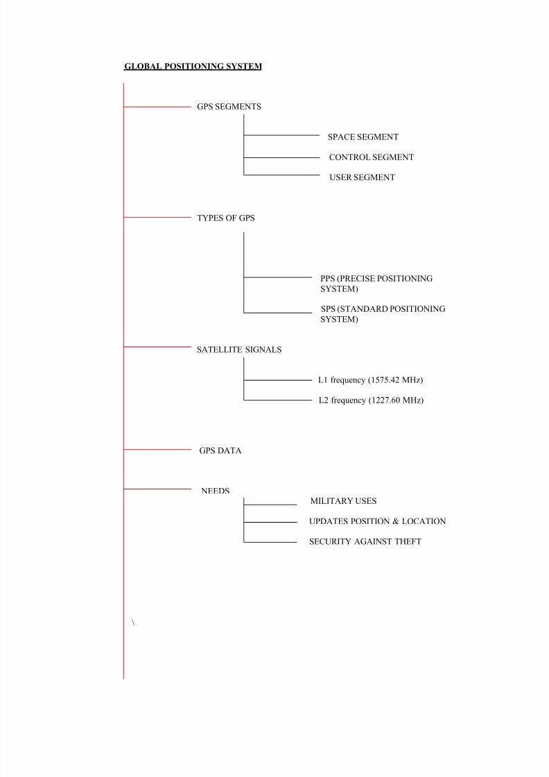
GLOBAL POSITIONING SYSTEM
GPS SEGMENTS
SPACE SEGMENT
CONTROL SEGMENT
USER SEGMENT
TYPES OF GPS
PPS (PRECISE POSITIONING
SYSTEM)
SPS (STANDARD POSITIONING
SYSTEM)
SATELLITE SIGNALS
L1 frequency (1575.42 MHz)
L2 frequency (1227.60 MHz)
GPS DATA
NEEDSMILITARY USES
UPDATES POSITION & LOCATION
SECURITY AGAINST THEFT
\
8/8/2019 Report Gps Yash
http://slidepdf.com/reader/full/report-gps-yash 6/17
INTRODUCTIONWhat is GPS?
GPS, which stands for Global Positioning System, is the only system today able to
show you your exact position on the Earth anytime, in any weather, anywhere.
How it works?The GPS system consists of 24 satellites. The number may vary slightly as new ones
are launched and old ones are retired. Each satellite is in an 11,000 mile orbit and transmits avery weak signal. The system is monitored and maintained by the U.S. Military. The satellitesonly broadcast to the user and the user only receives. There is no charge for use.
To start with, assume that all of the satellites and the receiver have a perfect internalclock. This is not the case, but it makes a good starting point. Each satellite transmits a codedsignal. Consider this signal to be like the peaks and ridges along the edge of a super long key.This code is generated as a function of time. The receiver is also able to generate the samecode. The receiver matches the incoming code to the internally generated code except thatthere is a delay caused by the signalµs travel time between the satellite and the receiver. Thereceiver measures how much it has had to shift the timing of its code to match the incomingcode. Since the receiver knows how much time it took the signal to reach the receiver and thespeed of travel of the signal, it can then calculate the distance from the satellite.
If you know how far you are from one satellite then you know that you aresomewhere along an imaginary sphere around that satellite. If you know how far you are
from two satellites, then you are somewhere along the intersection of where these twospheres, which is a circle. If you add another satellite, then you are somewhere where this
third sphere intercepts the circle created by the intersection of the other two spheres. Thesphere will most likely intercept the previous circle at two points. One of these points is
where you are, and the other is not a reasonable solution ± somewhere in outer space. Thus by knowing where you are relative to these three satellites the receiver with a perfect clock
can know where it is.
Although no clock is perfect, the satellites have atomic clocks²pretty close. Theclock in the GPS receiver is closer in technology to an inexpensive digital watch. Lighttravels at 186,000 miles per second. If the receiver time was off by 1/100 of a second thecalculated distance would be off by 1,860 miles.
For each receiver to have its own cesium clock would make GPS technology prohibitively expensive and non-portable. What the GPS receiver does is to use a cheap clock similar to a digital watch and add one more satellite to the calculation to correct the time inthe receiver. The receiver shifts the time calculation back and forth so that all of theimaginary spheres around the satellites intercept at one point.
For three-dimensional navigation you need to receive four satellites. Think of it as one
satellite for each dimension and one for the time. For two-dimensional navigation you canscrape by with only receiving three satellites. If you know your altitude, the GPS can treat the
center of the earth as a satellite reducing the number of required satellites by one. Your distance from the center of the earth is the radius of the earth plus your altitude. This is why
aviation GPS models have barometric altimeter input and you may occasionally see ahandheld GPS ask for your altitude during poor reception conditions.
Newer GPS receivers use the extra signals above the minimum that is required tofurther refine the position for increased accuracy. This is known as an over determinedsolution
8/8/2019 Report Gps Yash
http://slidepdf.com/reader/full/report-gps-yash 7/17
Segments of GPS
There are three segments of GPS
GPS SEGMENTS
SPACE SEGMENT
C NTR SEGMENT
USER SEGMENT
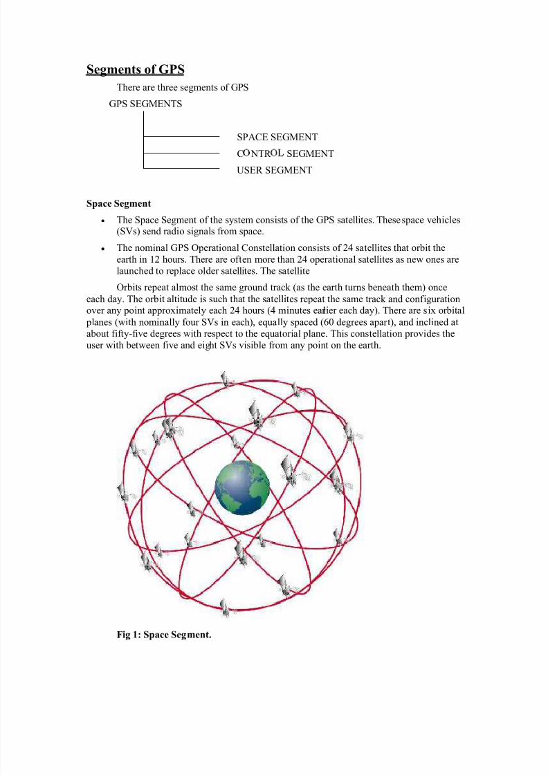
Space Segment
y The Space Segment of the system consists of the GPS satellites. These space vehicles(SVs) send radio signals from space.
y The nominal GPS Operational Constellation consists of 24 satellites that orbit the
ear th in 12 hours. There are of ten more than 24 operational satellites as new ones are
launched to replace older satellites. The satellite
Orbits repeat almost the same ground track (as the ear th turns beneath them) once
each day. The orbit altitude is such that the satellites repeat the same track and conf igurationover any point approximately each 24 hours (4 minutes ear lier each day). There are six orbital
planes (with nominally four SVs in each), equally spaced (60 degrees apar t), and inclined at about f if ty-f ive degrees with respect to the equator ial plane. This constellation provides the
user with between f ive and eight SVs visi ble from any point on the ear th.
Fig 1: Space Segment.
8/8/2019 Report Gps Yash
http://slidepdf.com/reader/full/report-gps-yash 8/17
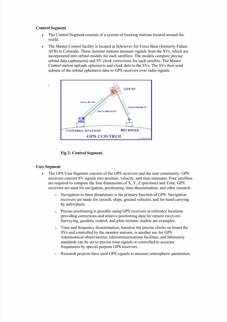
Control Segment
y The Control Segment consists of a system of track ing stations located around the
wor ld.
y The Master Control facility is located at Schr iever Air Force Base (former ly Falcon
AFB) in Colorado. These monitor stations measure signals from the SVs, which are
incorporated into orbital models for each satellites. The models compute preciseorbital data (ephemer is) and SV clock corrections for each satellite. The Master Control station uploads ephemer is and clock data to the SVs. The SVs then send
subsets of the orbital ephemer is data to GPS receivers over radio signals.
.
Fig 2: Control Segment.
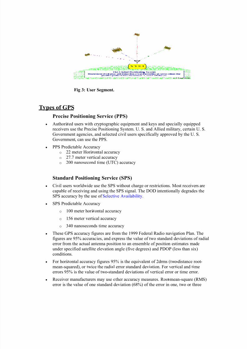
User Segment
y The GPS User Segment consists of the GPS receivers and the user community. GPS
receivers conver t SV signals into position, velocity, and time estimates. Four satellitesare required to compute the four dimensions of X, Y, Z (position) and Time. GPS
receivers are used for navigation, positioning, time dissemination, and other research.
o Navigation in three dimensions is the pr imary function of GPS. Navigation
receivers are made for aircraf t, shi ps, ground vehicles, and for hand carrying by individuals.
o Precise positioning is possi ble using GPS receivers at reference locations
providing corrections and relative positioning data for remote receivers.
Surveying, geodetic control, and plate tectonic studies are examples.
o Time and frequency dissemination, based on the precise clocks on board the
SVs and controlled by the monitor stations, is another use for GPS.Astronomical observator ies, telecommunications facilities, and laboratory
standards can be set to precise time signals or controlled to accuratefrequencies by special purpose GPS receivers.
o R esearch pro jects have used GPS signals to measure atmospher ic parameters.
8/8/2019 Report Gps Yash
http://slidepdf.com/reader/full/report-gps-yash 9/17
Fig 3: User Segment.
T pes of GPS
Precise Positioning Service (PPS)
y Author i ed users with cryptographic equi pment and keys and specially equi ppedreceivers use the Precise Positioning System. U. S. and Allied military, cer tain U. S.
Government agencies, and selected civil users specif ically approved by the U. S.
Government, can use the PPS.
y PPS Predictable Accuracy
o 22 meter Hor i ontal accuracy
o 27.7 meter ver tical accuracy
o 200 nanosecond time (UTC) accuracy
Standard Positioning Service (SPS)
y Civil users wor ldwide use the SPS without charge or restr ictions. Most receivers are
capable of receiving and using the SPS signal. The DOD intentionally degrades the
SPS accuracy by the use of Selective Availability.
y SPS Predictable Accuracy
o 100 meter hor i ontal accuracy
o 156 meter ver tical accuracy
o 340 nanoseconds time accuracy
y These GPS accuracy f igures are from the 1999 Federal R adio navigation Plan. The
f igures are 95% accuracies, and express the value of two standard deviations of radial
error from the actual antenna position to an ensemble of position estimates madeunder specif ied satellite elevation angle (f ive degrees) and PDOP (less than six)
conditions.
y For hor i ontal accuracy f igures 95% is the equivalent of 2drms (two-distance root-mean-squared), or twice the radial error standard deviation. For ver tical and timeerrors 95% is the value of two-standard deviations of ver tical error or time error.
y R eceiver manufacturers may use other accuracy measures. R oot-mean-square (RMS)
error is the value of one standard deviation (68%) of the error in one, two or three
8/8/2019 Report Gps Yash
http://slidepdf.com/reader/full/report-gps-yash 10/17
dimensions. Circular Error Probable (CEP) is the value of the radius of a circle,centered at the actual position that contains 50% of the position estimates. Spherical
Error Probable (SEP) is the spherical equivalent of CEP, that is the radius of a sphere,centered at the actual position that contains 50% of the three dimension position
estimates. As opposed to 2drms, drms, or RMS figures, CEP and SEP are not affected by large blunder errors making them an overly optimistic accuracy measure some
receiver specification sheets list horizontal accuracy in RMS or CEP and withoutSelective Availability, making those receivers appear more accurate than thosespecified by more responsible vendors using more conservative error measures.
Selective Availability, SA
SA is an intentional error introduced into the GPS signal to make it less accurate.Although I suppose that the military could turn it on again, SA no longer exists. I mention it
because you may see it in mentioned in literature on GPS.
Not only is GPS good for flying airplanes, but it is good for guiding bombs andmissiles. To prevent somebody else from doing this well, the military added a little randomtime shift to the satellite signal available for civilian use. This added some inaccuracy to thecalculated position.
Error correction technologies such as differential GPS, WAAS, and LAAS take outmuch of the SA induced error. Thus a sophisticated enemy could negate the effects. Thus,selective availability was turned off.
GPS Satellite Signals
The SVs transmit two microwave carrier signals. The L1 frequency (1575.42 MHz)carries the navigation message and the SPS code signals. The L2 frequency (1227.60 MHz) isused to measure the ionospheric delay by PPS equipped receivers.
y Three binary codes shift the L1 and/or L2 carrier phase.
o The C/A Code (Coarse Acquisition) modulates the L1 carrier phase. The C/Acode is a repeating 1 MHz Pseudo Random Noise (PRN) Code. This noise-likecode modulates the L1 carrier signal, "spreading" the spectrum over a 1 MHz
bandwidth. The C/A code repeats every 1023 bits (one millisecond). There is a
different C/A code PRN for each SV. GPS satellites are often identified bytheir PRN number, the unique identifier for each pseudo-random-noise code.The C/A code that modulates the L1 carrier is the basis for the civil SPS.
o The P-Code (Precise) modulates both the L1 and L2 carrier phases. The P-Code is a very long (seven days) 10 MHz PRN code. In the Anti-Spoofing(AS) mode of operation, the P-Code is encrypted into the Y-Code. Theencrypted Y-Code requires a classified AS Module for each receiver channeland is for use only by authorized users with cryptographic keys. The P (Y)-Code is the basis for the PPS.
8/8/2019 Report Gps Yash
http://slidepdf.com/reader/full/report-gps-yash 11/17
o The Navigation Message also modulates the L1-C/A code signal. The Navigation Message is a 50 Hz signal consisting of data bits that describe the
GPS satellite orbits, clock corrections, and other system parameters.
GPS Data
GPS Data
y The GPS Navigation Message consists of time-tagged data bits marking the time of transmission of each sub frame at the time they are transmitted by the SV. A data bitframe consists of 1500 bits divided into five 300-bit sub frames. A data frame istransmitted every thirty seconds. Three six-second sub frames contain orbital andclock data. SV Clock corrections are sent in sub frame one and precise SV orbital datasets (ephemeris data parameters) for the transmitting SV are sent in sub frames twoand three. Sub frames four and five are used to transmit different pages of systemdata. An entire set of twenty-five frames (125 sub frames) makes up the complete
Navigation Message that is sent over a 12.5-minute period.Data frames (1500 bits) aresent every thirty seconds. Each frame consists of five sub frames.Data bit sub frames(300 bits transmitted over six seconds) contain parity bits that allow for data checkingand limited error correction.
y Clock data parameters describe the SV clock and its relationship to GPS time.Ephemeris data parameters describe SV orbits for short sections of the satellite orbits.
Normally, a receiver gathers new ephemeris data each hour, but can use old data for up to four hours without much error. The ephemeris parameters are used with analgorithm that computes the SV position for any time within the period of the orbitdescribed by the ephemeris parameter set.
y Almanacs are approximate orbital data parameters for all SVs. The ten-parameter almanacs describe SV orbits over extended periods of time (useful for months in somecases) and a set for all SVs are sent by each SV over a period of 12.5 minutes (atleast). Signal acquisition time on receiver start-up can be significantly aided by theavailability of current almanacs. The approximate orbital data is used to preset thereceiver with the approximate position and carrier Doppler frequency (the frequencyshift caused by the rate of change in range to the moving SV) of each SV in theconstellation.
y Each complete SV data set includes an ionospheric model that is used in the receiver to approximate the phase delay through the ionosphere at any location and time. EachSV sends the amount to which GPS Time is offset from Universal Coordinated Time.The receiver to set UTC to within 100 ns can use this correction. Other system
parameters and flags are sent that characterize details of the system.
Position and time from GPS
Code Phase Tracking (Navigation)
y The GPS receiver produces replicas of the C/A and/or P (Y)-Code. Each PRN code isa noise-like, but pre-determined, unique series of bits.The receiver produces the C/Acode sequence for a specific SV with some form of a C/A code generator. Modernreceivers usually store a complete set of recomputed C/A code chips in memory, but a
8/8/2019 Report Gps Yash
http://slidepdf.com/reader/full/report-gps-yash 12/17
hardware, shift register, implementation can also be used. The C/A code generator produces a different 1023-chip sequence for each phase tap setting. In a shift register
implementation the code chips are shifted in time by slewing the clock that controlsthe shift registers. In a memory lookup scheme the required code chips are retrieved
from memory.The C/A code generator repeats the same 1023-chip PRN-codesequence every millisecond. PRN codes are defined for 32 satellite identification
numbers.
y The receiver slides a replica of the code in time until there is correlation with the SVcode. If the receiver applies a different PRN code to an SV signal there is nocorrelation. When the receiver uses the same code as the SV and the codes begin toline up, some signal power is detected. As the SV and receiver codes line upcompletely, the spread-spectrum carrier signal is de-spread and full signal power isdetected.
y A GPS receiver uses the detected signal power in the correlated signal to align theC/A code in the receiver with the code in the SV signal. Usually a late version of thecode is compared with an early version to insure that the correlation peak is tracked.
y A phase locked loop that can lock to either a positive or negative half-cycle (a bi- phase lock loop) is used to demodulate the 50 HZ navigation message from the GPScarrier signal. The same loop can be used to measure and track the carrier frequency(Doppler shift) and by keeping track of the changes to the numerically controlledoscillator; carrier frequency phase can be tracked and measured.
y The receiver PRN code start position at the time of full correlation is the time of arrival (TOA) of the SV PRN at receiver. This TOA is a measure of the range to SVoffset by the amount to which the receiver clock is offset from GPS time. This TOA iscalled the pseudo-range.
GPS Error sources
y GPS errors are a combination of noise, bias, and blunders.
y Noise errors are the combined effect of PRN code noise (around 1 meter) and noisewithin the receiver noise (around 1 meter).
y Selective Availability (SA)
y SA is the intentional degradation of the SPS signals by a time varying bias. SA iscontrolled by the DOD to limit accuracy for non-U. S. Military and government users.The potential accuracy of the C/A code of around 30 meters is reduced to 100 meters (twostandard deviations).
y The SA bias on each satellite signal is different, and so the resulting position solution is afunction of the combined SA bias from each SV used in the navigation solution. BecauseSA is a changing bias with low frequency terms in excess of a few hours, positionsolutions or individual SV pseudo-ranges cannot be effectively averaged over periodsshorter than a few hours. Differential corrections must be updated at a rate less than thecorrelation time of SA (and other bias errors).
y Other Bias Error sources;
y SV clock errors uncorrected by Control Segment can result in one-meter errors.
y Ephemeris data errors: 1 meter
8/8/2019 Report Gps Yash
http://slidepdf.com/reader/full/report-gps-yash 13/17
y Tropospheric delays: 1 meter. The troposphere is the lower part (ground level to from 8 to13 km) of the atmosphere that experiences the changes in temperature, pressure, andhumidity associated with weather changes. Complex models of tropospheric delay requireestimates or measurements of these parameters.
y Unmodeled ionosphere delays: 10 meters. The ionosphere is the layer of the atmosphere
from 50 to 500 km that consists of ionized air. The transmitted model can only removeabout half of the possible 70 ns of delay leaving a ten meter un-modeled residual.
y Multipath: 0.5 meters. Multipath is caused by reflected signals from surfaces near thereceiver that can either interfere with or be mistaken for the signal that follows thestraight-line path from the satellite. Multipath is difficult to detect and sometime hard toavoid.
y Blunders can result in errors of hundred of kilometers.
y Control segment mistakes due to computer or human error can cause errors from onemeter to hundreds of kilometers.
y User mistakes, including incorrect geodetic datum selection, can cause errors from 1 to
hundreds of meters.y Receiver errors from software or hardware failures can cause blunder errors of any size.
a. AVL Information:
Automatic Vehicle Location (AVL) is a technology used for tracking vehicles. Eachvehicle unit has a GPS receiver that reports its position to the base station over acommunication network (VHF Link). As, there is more than one location (Base Station); the
positional data received from a vehicle unit is retransmitted to a Main Control Station througha communication link. This allows the main control station and the base station to monitor the
entire fleet and manage the mobile assets.
The Global Positioning System (GPS), which provides data on location, time andvelocity continuously during any weather, has revolutionized the capability to locate anobject in 3D space. But the most crucial part of any tracking system is the datacommunication link, to the extent that the integrity of the tracking system is almost whollydependent on the integrity of the communication system being used within it.
Today, the three prime media being used in vehicle tracking applications areConventional Radio, Cellular, and Satellite Communication. Conventional Radio is typically
used in tracking systems that are confined to region where the limited range associated withConventional Radio is not a factor. Cellular Communication is often chosen for a system inwhich the vehicles range across several regions or an entire continent and where the cellular network has a high level of homogeneity and few ³dead´ spots. Satellite communication ischosen for fleet management on an international or global basis.
With Windows 95/NT, as the foundation, the vehicular hardware suite can be openedup to support not only the tracking function, but in-vehicle navigation, word processing, real-
8/8/2019 Report Gps Yash
http://slidepdf.com/reader/full/report-gps-yash 14/17
time data transfer & a multitude of other mobile office applications, that together will carryfleet management and mobile computing well into the next century.
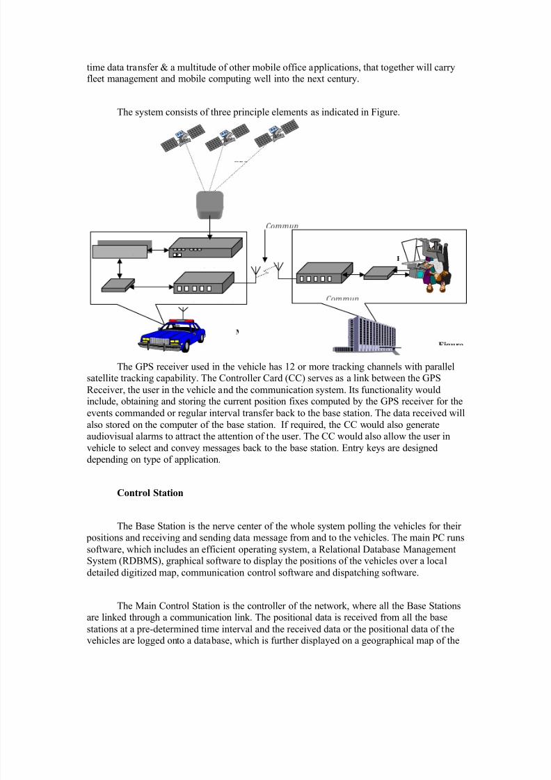
The system consists of three principle elements as indicated in Figure.
The GPS receiver used in the vehicle has 12 or more tracking channels with parallelsatellite tracking capability. The Controller Card (CC) serves as a link between the GPSReceiver, the user in the vehicle and the communication system. Its functionality wouldinclude, obtaining and storing the current position fixes computed by the GPS receiver for the
events commanded or regular interval transfer back to the base station. The data received willalso stored on the computer of the base station. If required, the CC would also generateaudiovisual alarms to attract the attention of the user. The CC would also allow the user invehicle to select and convey messages back to the base station. Entry keys are designeddepending on type of application.
Control Station
The Base Station is the nerve center of the whole system polling the vehicles for their positions and receiving and sending data message from and to the vehicles. The main PC runs
software, which includes an efficient operating system, a Relational Database ManagementSystem (RDBMS), graphical software to display the positions of the vehicles over a localdetailed digitized map, communication control software and dispatching software.
The Main Control Station is the controller of the network, where all the Base Stationsare linked through a communication link. The positional data is received from all the basestations at a pre-determined time interval and the received data or the positional data of thevehicles are logged onto a database, which is further displayed on a geographical map of the
8/8/2019 Report Gps Yash
http://slidepdf.com/reader/full/report-gps-yash 15/17
state. Thus, a real-time monitoring of the Police Patrol Vehicles can be done. At the time of deployment of the system, each vehicle¶s information is entered into a database at the control
station. This data can be entered in a specific format to include vehicle description, vehicleidentification and any pertinent information or special needs, the vehicles may have. The
database software is also used to keep up-to-date information on the movements of thevehicles along with their defined schedules and destinations, if need be.
The graphical software provides a host of features to enable the operator to makequick position related assessments. The software provides zooming feature to enable a close-up view of the vehicle of interest and also an overall view by zooming out to be able to see allthe vehicles on the screen. Editing function on the digitized map provides demarcation of certain areas, which can be hazardous to the vehicles, and if a vehicle travel into such areas,an audiovisual alarm is activated which the operator proceeds to convey to the specific errantvehicle. Multiple window views provide both overall view and a close up view on the samescreen.
Messages from the control station to the vehicles can be both predefined or free formentry, since the entire resources of the powerful computer is available to the operator.Emergency messages from the vehicles can be made to generate audiovisual alarms at thecontrol station, to attract the operator¶s attention and demand an acknowledgment to ensurethat the message has been received and read. The basic data format employed for messageexchanges between the control station and the vehicles should include predefined codes in theheaders of each message to stimulate the desired response from the specific member of thesystem.
The control station will poll the vehicles for their positions using their identity codesin a sequential manner to cover all the vehicles in the database. If for reasons of
communication link masking, a particular vehicle does not respond the first time, the controlstation will execute retries for a definite number of attempts, which can be preset by theoperator depending on the importance of the vehicle in question.
Communication Link
At first glance, the AVL market place may seem to offer a host of communicationtechnologies for vehicle tracking applications. However, just by taking into account theapplication requirements, one or two technologies come into focus. The requirements mainlycover aspects such as reporting rate, throughput capacity, geographic coverage and cost.
There are two different types of communication links required in this solution. Thefirst link, between the vehicle units installed in the mobile vehicles and the base stations. Thesecond, between all the base stations and Main Control Station.
In the first link, the data is to be transferred to the next Base Station, which isapproximately at a distance of 45-50 Kilometers. Based on these, the most common type of
8/8/2019 Report Gps Yash
http://slidepdf.com/reader/full/report-gps-yash 16/17
communication system used in AVL design is the Conventional Land Mobile Radios. Thefrequency ranges normally used are VHF (136-175 MHz). Conventional LMR are portable
and can be dashboard mountable units. They are intended to operate in defined geographicalregions. In the second link, multiple data files have to be sent and the range to be covered is
more than 50kms. Police Organization's existing wireless link shall be utilized for the same.
GPS Techniques and Project Costs
y Receiver costs vary depending on capabilities. Small civil SPS receivers can be purchased for under $200, some can accept differential corrections. Receivers that canstore files for post-processing with base station file cost more ($2000-5000).Receivers that can act as DGPS reference receivers (computing & providingcorrection data) and carrier phase tracking receivers (and two are often required) cancost many thousands of dollars($5,000 to 40,000). Military GPS receivers may costmore or be difficult to obtain.
y Other costs include the cost of multiple receivers when needed, post-processingsoftware, and the cost of specially trained personnel.
y Project tasks can often be categorized by required accuracies, which will determineequipment cost.
o Low-cost, single-receiver SPS projects (100 meter accuracy)
o Medium-cost, differential SPS code Positioning (1-10 meter accuracy)
o High-cost, single-receiver PPS projects (20 meter accuracy)
o High-cost, differential carrier phase surveys (1 mm to 1 cm accuracy)
WEBSITES
Automatic Transfer Global Positioning System (GPS) Notes. Have moved to the Universityof Colorado at Boulder at the following address: ... Category: Science > Earth Sciences > Geomatics > GPS - Global Positioning System
www.utexas.edu/depts/grg/gcraft/notes/gps/gps.html - 2k - Cached - Similar pages
The Global Positioning System www.colorado.edu/geography/gcraft/notes/gps/gps_f.html - 1k ±
Category: Science > Earth Sciences > Geomatics > GPS - Global Positioning System www.gps-society.org/
Sam Wormley's Global Positioning System (GPS) Resources at ... ... common with the US' Global Positioning System (GPS) in terms of the satellite
constellation,orbits, and signal structure. Both systems are owned and operated ...
Category: Science > Earth Sciences > Geomatics > GPS -
8/8/2019 Report Gps Yash
http://slidepdf.com/reader/full/report-gps-yash 17/17
Global Positioning System > Guides
The GPS Resource Library «What is the GPS Resource Library? ... Global Positioning Systems FAQs. ... www.gpsy.com/gpsinfo/
GARMIN International - Global Positioning System Receivers - ... ... GARMIN International is the industry leader in GPStechnology and an innovator inconsumer electronics.Category:Science > Earth Sciences > ... > Manufacturers and Dealers > Manufacturers www.garmin.com/
Trimble - All About GPS ... How to Use this Tutorial. GPS is a complex ... of the explanationdevelops one step at a time. Start. ... www.trimble.com/gps/ - 10k - Cached - Similar pages
Trimble.com Joint Venture with Caterpillar, Trimble Survey Controller,
GPS Pathfinder Express, Contacts | Privacy ... Description: GPS equipment manufacturer for survey, mapping, marine, aviation, precisepositioning, military, vehicle...Category: Science > Earth Sciences > ... > Manufacturers and Dealers www.trimble.com/ - 9k - Cached - Similar pages - Stock quotes: TRMB [ More results from www.trimble.com ]