repairing & testing the world’s first
TRANSCRIPT

REPAIRING & TESTING THE WORLD’S FIRST
COMPUTER GRAPHICS CARDS:
THE MATROX ALT-256 and ALT-512.
(Dr. H. Holden. July 2019).
INTRODUCTION:
Early home computers in the 1970’s generally had text screens. The text characters
being stored in dedicated ROM IC’s. By the late 1970’s there was a hunger for graphics
screens in home computers. Matrox, a Canadian company, came up with the ALT-256.
This was the PCB which launched their company, which later became a $1Bn
enterprise.

The ALT-256 generated a 256 x 240 visible pixel display on a standard composite video
monitor.
The card itself has a single video plane and contained 38 TTL IC’s and 16 RAM IC’s.
The TMS4027 is used, although the original memory IC was cited as the “4096”. Each
of these IC’s has a storage capacity of 4096 locations and each IC has a one bit (on-off)
output. So no shades of grey with this output, the pixel is either ON or OFF.
However, with three cards combined, one output of each can be assigned to the R,G &
B channel of a color video system. And in that case, 8 shades of grey are possible on a
monochrome monitor.
Later Matrox produced the ALT-512 which was more advanced than the ALT-256 with
twice the memory. This accommodated two video planes and 4 shades of grey could be
attained from a single card by displaying two pixels (one from each plane) with different
intensity weighting simultaneously.
When Matrox released the ALT256 graphics card, around 1977, it was a revolutionary
step forward for S-100 computer owners interested in graphics. There was a review
article on the ALT- 256 in Byte Magazine in 1978. This was one remark after mentioning
three boards would do animation and a color display:
“For the Star Trek freak, now there is available a real (if imaginary) universe to save,
rather than a slow printer banging out descriptions. For the artist, a canvas; the
researcher, a window; and the kids, an electronic sketch pad”
Perhaps the word “freak” should have been “fan” to be more diplomatic.
However, those remarks are quite profound when one considers what computer
graphics cards in modern computers have evolved into since then. At the time the Byte
Magazine article also cited the price of the ALT-256 board at $395, which is about
$1669 in today’s dollars !
Matrox also produced a companion 2480 card, to generate text, which can be linked
with the ALT-256 for a simultaneous text and graphics display. The TV sync generators
on these boards can be master or slave and the video signals either from the graphics
card or the text card can be mixed so as to attain one video output signal.

REPAIRING MY ALT-256:
I acquired a board on eBay. My experience with the ALT-256 graphics card is very little
different than any vintage S-100 card from that era. There are usually one or two faulty
74LS series TTL IC’s and in cases where there are IC sockets, these sockets and the
IC pins require significant cleaning to re-establish a good connection between the
socket pins & IC pins.
In the case of the ALT-256 though, Matrox had decided not to use any sockets for any
of the IC’s. This in fact, for a card of this age, makes for a more reliable card. However
on the card I acquired there were two faulty IC’s (a 74LS367 and a 74LS04) in the TV
sync generator circuitry which had to be removed from the card and replaced with
suitable period correct IC’s. The fault finding was done with the aid of the schematic and
a 2465B Tek Oscilloscope. Also, somebody had worked on this pcb in the past, three
jumpers were cut, one IC pin cut and a 7812 regulator IC had failed. One TMS4027
RAM IC, A42, required replacing too. So likely, one can not expect to acquire a card of
this age and expect it to be working off the bat.
LOCATING FAULTY RAM IC’s in the ALT-256…A Simple RAM Diagnostic:
To aid in the physical location of a failed RAM IC on this card I have prepared the
following diagrams which explain which RAM IC on the board looks after which columns
of pixels on the display. One good thing about fault finding graphics cards with video
RAM is that the screen image serves as the diagnostic window which makes this easier.
Each of the TMS4027 RAM IC’s looks after an area of screen pixels in 16 vertical rows.
If each row were 256 pixels high then this would correspond to the 4096 single bit
storage locations within that IC. While these locations can be “written to” with software
commands, there are only 240 active scanning lines on the monitor (the remainder are
in the blanked out vertical retrace time) so vertically at least, only pixels on the Y axis
(labelled 0 to 239) are visible. On the other hand, on the x or horizontal axis, all 256
pixels are seen (labelled 0 to 255). In this video card, coordinates x=0 and y=0,
specified in the card’s registers, are at the top left hand corner of the image on the video
monitor.
The diagram below shows the physical layout and numbering of the RAM IC’s on the
card, top view:

FIG. 1
With a RAM IC failure, the output pin (pin 14 on the TMS4027) could be stuck low, or
high. In the case it is stuck high 16 rows of vertical pixels will be turned on. These will
only be seen easily of course if the background or all surrounding pixels are off. The
better way to see these pixels it to clear the screen (switch all pixels off). To switch all
pixels off can be simply done in BASIC and assuming the address jumpers on the pcb
are set so that A7,A6,A5,A4,A3 & A2 are tied low. The Erase port address is 03:
OUT 3,0 ; sets all pixels off.
Conversely, if a RAM IC output is stuck low, to see it, all the pixels need to be set on:
OUT 3,1 ; sets all pixels on.
(In my SOL-20 computer I run MBASIC in CP/M)
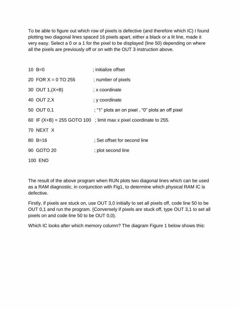
To be able to figure out which row of pixels is defective (and therefore which IC) I found
plotting two diagonal lines spaced 16 pixels apart, either a black or a lit line, made it
very easy. Select a 0 or a 1 for the pixel to be displayed (line 50) depending on where
all the pixels are previously off or on with the OUT 3 instruction above.
10 B=0 ; initialize offset
20 FOR X = 0 TO 255 ; number of pixels
30 OUT 1,(X+B) ; x coordinate
40 OUT 2,X ; y coordinate
50 OUT 0,1 ; “1” plots an on pixel , “0” plots an off pixel
60 IF (X+B) = 255 GOTO 100 ; limit max x pixel coordinate to 255.
70 NEXT X
80 B=16 ; Set offset for second line
90 GOTO 20 ; plot second line
100 END
The result of the above program when RUN plots two diagonal lines which can be used
as a RAM diagnostic, in conjunction with Fig1, to determine which physical RAM IC is
defective.
Firstly, if pixels are stuck on, use OUT 3,0 initially to set all pixels off, code line 50 to be
OUT 0,1 and run the program. (Conversely if pixels are stuck off, type OUT 3,1 to set all
pixels on and code line 50 to be OUT 0,0).
Which IC looks after which memory column? The diagram Figure 1 below shows this:

The boxes in grey represent the lines plotted by the BASIC program, called “Locator
Lines”. The columns looked after by each RAM IC are shown at the top. As can be
seen, for this example (where IC A42 has failed) the defect is in the 6th column.
Therefore, by examining the video display, where the locator lines and the defective
pixel coincide, the failed column can be found and the IC corresponding to it physically
located. The purpose of the lines being diagonal is to make it easy to visually count the
pixels, which is very difficult if they are on the same row.
The result is shown below, in this example IC A42 has failed, its output, pin 14 being
stuck high:

The result below shows the fault when the pin 14 of A42 is stuck low and the locator
lines are plotted in black and all other pixels switched on. It is very easy to count along
the pixels on the x axis to see that it is column 6, 22, 38 etc that is defective and from
figure 1 see that A42 is responsible.

If there were single or more defective pixels, related to one or more of the 4096
locations inside a single TMS4027 IC, these would show up somewhere in one of the
columns supported by that IC.
Images on the ALT-256:
Matrox published a software package called MTXGRAPH, as a .PRN listing in the ALT
256 manual.
Presumably this software was also on disk at the time, but it would be very rare now I
would think. I plan to assemble and test this software in the future. For now though it
was preferable to write my own to test the card.
The photo below shows an image displayed by the ALT-256. This image started out as
a 180kB .BMP and was processed to be able to display it in the SOL-20 computer with
this card. (The method of how this was done is essentially the same as for the images
displayed by the ALT-512 card…see that section below). This image was drawn in
Microsoft Picture It by tracing over some drawings of the DeLorean and saved as a
180kB, 256 x240 pixel .bmp monochrome image. The wheel hubs were the most
difficult part. Also I found a better result is to draw in the native resolution, than start with
a big pre-existing file and try to reduce its pixel count.

I also wrote an image file for a reversed (negative image). This is also easy to do at the
hardware by inverting the video (and not the sync), however the ALT-256 does not have
this facility so it required a separate image file.
Probably this ALT-256 card has not produced any graphics since the 1970’s, so it was a
very rewarding experience to see this image come up after the work required to process
the image file to suit the card.

THE MATROX ALT-512:
It could be said that since the ALT-256 was one of the world’s first computer graphics
cards, the ALT-512 might have been the second. However around that time in the
1970’s other companies such as Vector Graphics were producing S-100 graphics cards
too.
The ALT-512 which followed the ALT-256 was unique in that it had enough video ram
on the one board that it has two planes, both 256 x 240 pixels and moreover the two
planes can be viewed simultaneously with the A plane having twice the intensity of the
B plane , see below. This allowed for a 4 shade of grey image with the right
programming of the two planes.
REPAIRING & TESTING THE ALT-512:
The card I bought on Ebay appeared to be new, however it was dead. The video sync
circuitry was not normal. Investigation showed that the video sync generator circuits
were being reset before the second counter in the chain, IC A2, had reached its terminal
count. A 74LS00 quad dual input NAND gate in the gating circuits around the counter
had failed in a very unusual manner (I have not seen a 74 series IC with this fault
before). Even though one of the gate’s inputs was low, the output of the gate (with a
normal output swing) was responding to the other input. Exactly as though the actual
input pin which was held low externally, leading to the logic circuitry inside the gate, had
gone open circuit inside the IC and assumed a logic high state. Once this IC was
replaced, the card sprang to life.
The Photo below shows the ALT-512 card:

I found that a checkerboard pattern was very easy to plot in BASIC, but very slow to
load taking 15 minutes or more.
The ALT-512 has two video planes and a total of 8 display modes. These modes select
which plane is plotted or viewed and how the two planes are displayed, singly or mixed
together. With different weighting on planes A & B, 4 shades of grey are possible due to
this function.
I wrote an 8080 Assembly Language program (GRPH3.COM) to plot any pixel size
checkerboard to either video plane (takes a few seconds to plot) and then be able to
select from the keyboard the various output modes to combine the images. When this
was done all sorts of interesting patterns were possible, depending of the relative size of
the checkerboards on each plane. I have included an assortment of results with different
sized checkerboards and various output plane register combinations and obviously
images here were photographed on an Amber VDU (the A label on the VDU panel has
nothing to do with the planes):


As noted four shades of grey are available in two of the modes because plane A has
twice the weighting (video amplitude) of plane B and they are logically OR’d in one
mode and each pixel displayed on top of the other. Therefore there are 4 possible video
amplitude levels for each visible pixel in the 256 x 240 pixel array, off (black), dark grey,
light grey and white, assuming a white (P4) phosphor monochrome VDU:
Plotting a Picture to display with the ALT-512:
This initial result with the checkerboards got me wondering what sort of “photographic
image” the ALT-512 could produce.
It would require the two planes be plotted separately and displayed simultaneously and
the byte values for the pixel array would not have to use up too much memory. I have
48k of RAM in my SOL-20 (three PT 16kRA ram cards) running 48k CP/M.
For each pixel plane one byte could hold 8 consecutive pixel values, so 256/8 = 32
bytes per video line and 240 lines tall, so in theory at least 7680 bytes could hold the
data to plot one plane. Therefore, the image file (when created see below) would use up
15,360 bytes or 15kB of memory when loaded into the SOL. That would consume the
storage capacity of one of the three 16kRA memory cards in my SOL pretty much
entirely.
I looked around to see what a 4 grey scale image might look like and found one in an
old video game. Zoomed back so the apparent pixel size seen on the screen here would
be roughly about the same as it would be with the ALT-512 running into about a 7”
video monitor:

This made me realise that a 4 grey level image in a 256 x 240 pixel array could in fact
look “respectable”.
The next question became how to create the 15kB file from a video image in the correct
format and get it into the SOL’s memory for loading into the two planes of the ALT-512
graphics card.
It could come across in the usual way as a .ENT file on the serial link, or perhaps
transferred to the SOL with the Xmodem protocol using PCGET.
Once it was there, in the SOL’s RAM, I could write an 8080 assembly language program
to use that data array to program the ALT-512 card. Clearly this was the sort of job that
might be helped with the use of Photo Studio and a custom program in a more modern
computer to initially have the image formatted for the correct number of pixels.
Starting with a file for each plane, where all the bytes (and bits corresponding to each
pixel) where initially zero, then looking at the diagram on the previous page, the
software creating the pixel (bit) on-off values would switch on the bits for the plane B file
with a dark grey or white level in the 4 grey scale image, and for the plane A file switch
on the bits with either light grey or white in the 4 grey scale image.
Most modern image software though works with 256 levels and in a Bitmap image for
example, each pixel is represented by 3 sequential bytes, with each byte holding 00-FF
representing the intensity of the 3 primary colors:

In the case where the image was formatted in photo editing software as a monochrome
image, simply the value of the bytes represented for each color are the same, so the
byte value, representing the intensity is simply duplicated three times for each pixel, so
that any two of them become redundant data. There are many .bmp formats it would
appear, this one is the “24 bit version” that is commonly used and used in my photo
editing software.
The first step in the process was to create a 256 x 240 pixel monochrome image in
Photo Editing software where the contrast is scaled so that the image whites, or a good
proportion of those, have a level of 255 or close and the range extending to black.
The following block diagram shows the method I used. The method is somewhat
cumbersome and depends on using DEBUG in the 5155. This was partly dictated by the
available data segment size in my 5155 computer (ignoring the extra segment). Also, at
this point I was not familiar with easy disk access of the files, so it was easier for me to
simply accommodate a whole file in a 64k Data segment at one time using DEBUG to
put it there. At the SOL-20 end I managed the disk file access to load the two 7.5kB
plane files to memory.
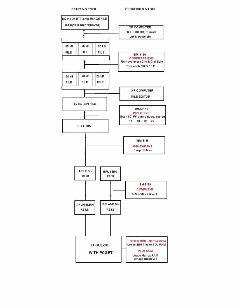

The 8088 assembly language program 4SPLIT.EXE was created in the 5155 to modify
the byte array. The 256 shade image file can be divided into four zones, to create
BFILE.BIN, a 256 x 240 = 61440 Bytes files where both nibbles are a zero or 1:
Byte values (in decimal): 0 to 63 defined as Black and assigned 00H
63 to 127 defined as dark Grey and assigned 01H
128 to 192 defined as light Grey and assigned 10H
191 to 255 defined as White and assigned 11H
BFILE.BIN now has the lower nibble encoding plane B. Byte array B now has its
nibbles swapped to create AFILE.BIN. Both of these files are still 61440 bytes long, far
too big to send to the SOL-20.
As shown BFILE and AFILE are then processed by the program COMP8.EXE to
compress them by a factor of 8, but without losing any of the 4 level grey level data to
create the two final files APLANE.BIN and BPLANE.BIN
This program masks off the upper nibble (discards it) and places the data from the
lower nibble of one byte into the most significant bit of a new byte, so in effect 8 bytes of
the B (or A) plane files get represented by one bit of a new byte, so the 60kB file s
divided by 8 to create a 7.5kB file.
Starting with the process to make the BPLANE file, where one byte in this 7.5kB file
represents 8 pixels in plane B:
Examine first Byte of BFILE, if 01 to create bit pattern: 1000 0000
Examine second Byte of BFILE, if 01 if 1 add to bit pattern: 1100 0000
If examined byte 0, move zero to appropriate bit position if not already zero.
And keep going until 8 bytes examined and a new byte is created from eight bytes
taken sequentially from the 60kB BFILE file.
This way a single byte of the created BPLANE file holds the value for 8 consecutive
pixels for use by the ALT-512 video card and the BPLANE file is now a “SOL-20
manageable” 7680 byte file. The process repeated for AFILE to create the APLANE
file, also 7680 bytes.
Once the APLANE & BPLANE files are in SOL-20 RAM at known addresses, they can
be read and loaded into the ALT-512 video planes with an 8080 assembly language
program to decode the bytes and display the picture. I loaded the BPLANE.BIN file to
address 4000H and the APLANE.BIN file to address 5E00H. Then I wrote the final 8080

program PLOT.COM to write the values into the ALT-512’s RAM, the result is shown
below, for two of the possible 8 video display modes. Images on Amber VDU:
The image is 7.5kB per PLANE, 256 x 240 pixel image, 4 shades of grey, output from
ALT 256. (one bit per pixel).

The ALT-512 allows the outputs from each plane to be displayed independently, or
together, with pixels directly on top of each other or interleaved. This is described in the
manual. The interleaved configuration makes the individual pixels readily visible as can
be seen in the image above.
Summary:
Matrox’s first two video card are really impressive I think and they were implemented
with nothing more than 74 series TTL IC’s and some low capacity memory. It is easy to
take modern high resolution color graphics for granted as they are now everywhere in
phones and various VDU’s and TV sets.
However, it is always worth looking back and seeing how a technology started out and
to appreciate where it came from. Also, it is fun and a technical challenge to repair and
restore vintage computers and the cards for them. Also it is challenging to write the
software to make them work.
****************************************************************************************************