repair information - eatonpub/@eaton/@hyd/... · a hydrostatic pump or motor. ... valve block...
TRANSCRIPT
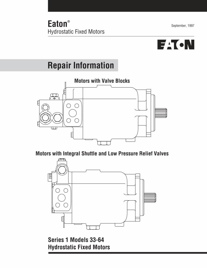
September, 1997Eaton®
Hydrostatic Fixed Motors
Repair Information
Series 1 Models 33-64Hydrostatic Fixed Motors
Motors with Valve Blocks
Motors with Integral Shuttle and Low Pressure Relief Valves
2
Table of ContentsPage
Introduction .............................................................................................................. 2Model Number System ............................................................................................. 3Exploded View .......................................................................................................... 4Part Description ........................................................................................................ 5Disassembly Shaft Seal ............................................................................................ 6Disassembly/Reassembly Valve Block ...................................................................... 7Disassembly End Cover ........................................................................................... 10Disassembly Rotating Group ................................................................................... 10Reassembly Rotating Group .................................................................................... 13Reassembly Bearing Plate ....................................................................................... 14Reassembly Shaft Seal ............................................................................................ 15Install Valve Block.................................................................................................... 17Torque Specifications .............................................................................................. 17
Introduction
The purpose of this manual is to provide you with service information and procedures fordisassembly and reassembly of Eaton Hydrostatic Fixed Displacement Motors (Series 1; Models 33,39, 46, 54, and 64). Motors with valve blocks and motors with integral shuttle and low pressure reliefvalves are covered. We feel the procedures outlined in this manual will allow you to better serviceyour motors and obtain the best results possible. To ensure accuracy of repair, and prevent part lossor damage, certain components or subassemblies are disassembled, inspected, and reassembledupon removal from the motor.
Note: All requests or inquiries must be accompanied by the complete model and serial number.
3
Tools Required
• Stationary Seal Puller (1/4 in. x 20 UNCCap Screw, 3 to 4 in. Long)
• Rotating Seal Puller (Special)
• Retaining Ring Pliers, No. 5 or 7
• Breaker Bar or Ratchet Wrench
• 1-3/8 in. Hex Wrench
• 1 in. Hex Wrench
• 9/16 in. Socket
• Torque Wrench (200 lb-ft Capacity)
• 1/4 in. Hex Bit Socket
• 1/4 in. Hex Key
• Loctite No. 271
• Pliers
• Punch
• Magnetic Base Indicator
• Hammer
• Bearing Press or Driver
• Light Petroleum Jelly (like Vaseline)
• Cleaning Solvent
• Two Headless 5/16 in. Cap Screws, 5 to 6 in.Long (Special)
• Micrometer or Vernier Calipers
• Small Screwdriver (1/8 in. Blade)
• Low Clearance Bearing Puller (Special)
• Clean Lint Free Rags
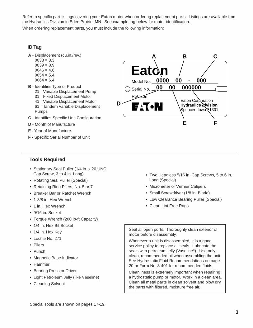
Refer to specific part listings covering your Eaton motor when ordering replacement parts. Listings are available fromthe Hydraulics Division in Eden Prairie, MN. See example tag below for motor identification.
When ordering replacement parts, you must include the following information:
Seal all open ports. Thoroughly clean exterior ofmotor before disassembly.
Whenever a unit is disassembled, it is a goodservice policy to replace all seals. Lubricate theseals with petroleum jelly (Vaseline®). Use onlyclean, recommended oil when assembling the unit.See Hydrostatic Fluid Recommendations on page20 or Form No. 3-401 for recommended fluids.
Cleanliness is extremely important when repairinga hydrostatic pump or motor. Work in a clean area.Clean all metal parts in clean solvent and blow drythe parts with filtered, moisture free air.
Special Tools are shown on pages 17-19.
A - Displacement (cu.in./rev.)0033 = 3.30039 = 3.90046 = 4.60054 = 5.40064 = 6.4
B - Identifies Type of Product21 =Variable Displacement Pump31 =Fixed Displacement Motor41 =Variable Displacement Motor61 =Tandem Variable DisplacementPumps
C - Identifies Specific Unit Configuration
D - Month of Manufacture
E - Year of Manufacture
F - Specific Serial Number of Unit
EatonModel No.
Serial No.
RotationEaton CorporationHydraulics DivisionSpencer, Iowa 51301
A B C
E
D
F
0000 00 - 00000 00 000000
ID Tag
4

5
25
26
5049
4827
22
47
29
30
56
5758
59
55
54
51
5049
48
52
53
End Cover with Integral Shuttleand Low Pressure Relief Valve
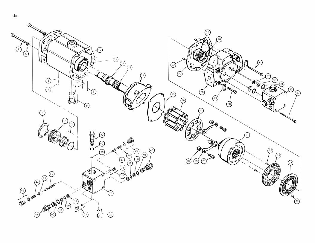
ItemNo. Description Qty.18 Spacer .......................................................................................... 419 Retaining Strap ............................................................................ 220 Cap Screw .................................................................................... 421 Cylinder Barrel Assembly ............................................................. 122 Dowel Pin (5/16 x 5/8 long) ......................................................... 523 Bearing Plate ................................................................................ 124 Valve Plate .................................................................................... 125 End Cover Bearing Cup and Cone ................................................. 126 End Cover Bearing Shims ........................................................... A/R27 End Cover Gasket ......................................................................... 128 Standard Motor End Cover ........................................................... 129 Lifting Strap ................................................................................. 230 Hex Head Bolt ............................................................................... 231 Hex Head Bolt ............................................................................... 632 Square Cut Seal ............................................................................ 133 Back-up Washer ........................................................................... 234 O-ring ........................................................................................... 235 Valve Block Assembly .................................................................. 136 Hex Head Bolt ............................................................................... 437 Gauge Port Plug/O-ring ................................................................ 338 Back-up Ring ............................................................................... 439 O-ring ........................................................................................... 340 O-ring ........................................................................................... 341 High Pressure Relief Cartridge ..................................................... 242 Low Pressure Relief Cartridge ...................................................... 143 Shuttle Valve ................................................................................ 244 Shuttle Spring .............................................................................. 245 Shuttle Valve Plug/O-ring ............................................................. 246 Shuttle Spool ............................................................................... 147 Motor End Cover with Integral Shuttle and
Low Pressure Relief Valve ............................................................ 148 Shuttle Valve Plug/O-ring ............................................................. 249 Shuttle Spring .............................................................................. 250 Shuttle Valve ................................................................................ 251 Shuttle Spool ............................................................................... 152 Gauge Port Plug/O-ring ................................................................ 153 Gauge Port Plug/O-ring ................................................................ 254 Hex Head Bolt ............................................................................... 455 Cap Screw, Socket Head .............................................................. 256 Plunger ........................................................................................ 157 Spring .......................................................................................... 158 Low Pressure Relief Valve Shims ............................................... A/R59 Low Pressure Relief Valve Plug/O-ring ......................................... 1
A/R – As Required
ItemNo. Description Qty.
1 Retaining Ring ............................................................................. 12 Stationary Seal ............................................................................. 13 Rotating Seal and O-ring .............................................................. 14 Cap Screw .................................................................................... 25 Washer ......................................................................................... 26 Dowel Pin ..................................................................................... 17 Socket Pipe Plug (1/8-27) ............................................................ 18 Case Drain Plug/O-ring ................................................................. 19 I.D. Tag and Screws ..................................................................... 1
10 Fixed Motor Housing .................................................................... 111 Output Shaft Bearing Cup and Cone ............................................. 112 Retaining Ring ............................................................................. 113 Motor Drive Shaft ......................................................................... 114 Swashplate ................................................................................... 115 Thrust plate .................................................................................. 116 Piston and Slipper Assembly ........................................................ 917 Slipper Retainer Plate ................................................................... 1
6
Important: Cleanliness is extremely important when repairing a hydrostatic pump or motor. Before disconnectingthe lines , clean foreign material from exterior of unit. Work in a clean area. Clean all metal parts in clean solvent.Blow parts dry with air. Don’t wipe parts with cloth or paper towel, because lint or other matter could causedamage. Check all mating surfaces. Replace any parts that have scratches or burrs that could cause leakage.Don’t use coarse grit paper, piles or grinders on parts.
Note: All torque specifications are for lubricated threads. Bolts for gasketed surfaces should be retorqued asecond time.
A good service policy is to replace all old seals with new seals whenever unit is disassembled. Lubricate seals(except metal sealing surfaces of shaft seal assembly) with petroleum jelly. Use only clean, recommended oilwhen assembling unit. See Fluid Recommendation Form 3-401.
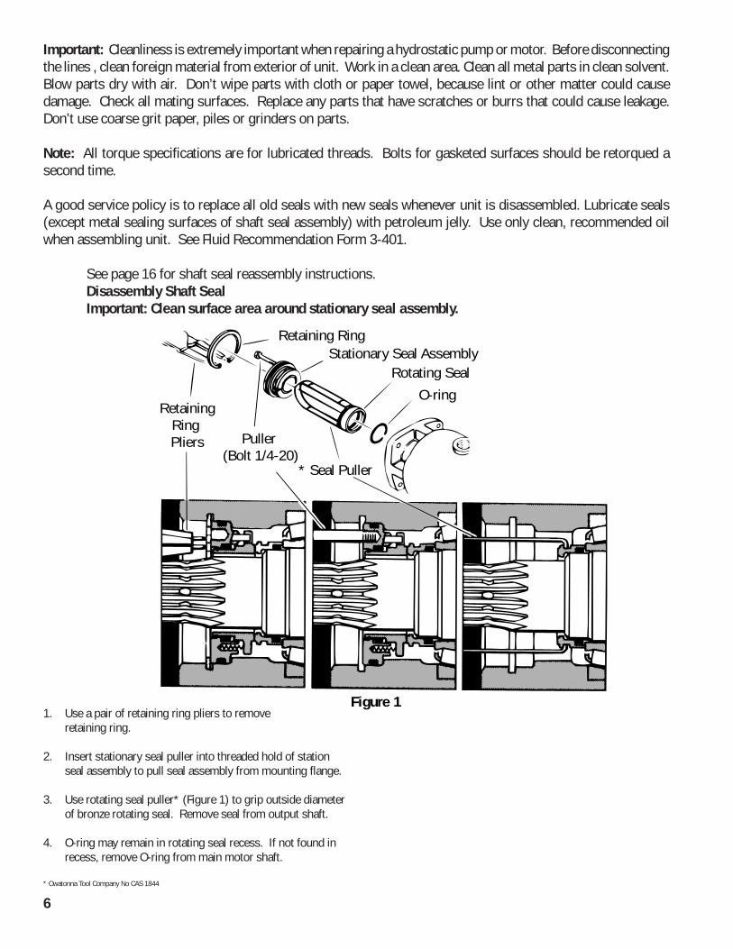
See page 16 for shaft seal reassembly instructions.Disassembly Shaft SealImportant: Clean surface area around stationary seal assembly.
1. Use a pair of retaining ring pliers to removeretaining ring.
2. Insert stationary seal puller into threaded hold of stationseal assembly to pull seal assembly from mounting flange.
3. Use rotating seal puller* (Figure 1) to grip outside diameterof bronze rotating seal. Remove seal from output shaft.
4. O-ring may remain in rotating seal recess. If not found inrecess, remove O-ring from main motor shaft.
* Owatonna Tool Company No CAS 1844
Retaining RingStationary Seal Assembly
Rotating Seal
O-ring
* Seal Puller
Puller (Bolt 1/4-20)
RetainingRing Pliers
Figure 1
7
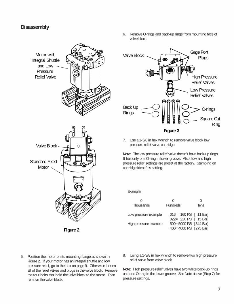
Motor withIntegral Shuttle
and LowPressure
Relief Valve
Valve Block
Standard FixedMotor
Figure 2
Disassembly
5. Position the motor on its mounting flange as shown inFigure 2. If your motor has an integral shuttle and lowpressure relief, go to the box on page 9. Otherwise loosenall of the relief valves and plugs in the valve block. Removethe four bolts that hold the valve block to the motor. Thenremove the valve block.
6. Remove O-rings and back-up rings from mounting face ofvalve block.
7. Use a 1-3/8 in hex wrench to remove valve block lowpressure relief valve cartridge.
Note: The low pressure relief valve doesn’t have back-up rings.It has only one O-ring in lower groove. Also, low and highpressure relief settings are preset at the factory. Stamping oncartridge identifies setting.
8. Using a 1-3/8 in hex wrench to remove two high pressurerelief valve from valve block.
Note: High pressure relief valves have two white back-up ringsand one O-ring in the lower groove. See Note above (Step 7) forpressure settings.
Valve Block
Figure 3
Back UpRings
Gage PortPlugs
High Pressure Relief Valves
Low PressureRelief Valves
O-rings
Square CutRing
Example:
0 0 0Thousands Hundreds Tens
Low pressure example: 016= 160 PSI [ 11 Bar]022= 220 PSI [ 15 Bar]
High pressure example: 500= 5000 PSI [344 Bar]400= 4000 PSI [275 Bar]
8
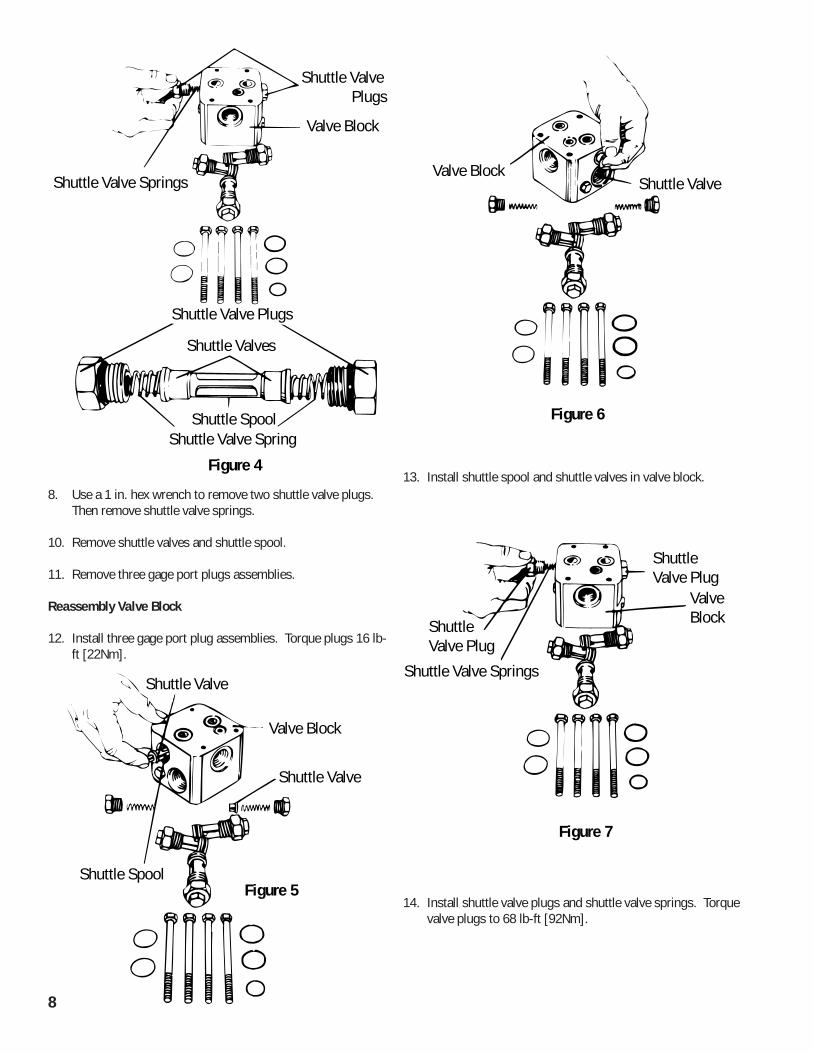
8. Use a 1 in. hex wrench to remove two shuttle valve plugs.Then remove shuttle valve springs.
10. Remove shuttle valves and shuttle spool.
11. Remove three gage port plugs assemblies.
Reassembly Valve Block
12. Install three gage port plug assemblies. Torque plugs 16 lb-ft [22Nm].
Shuttle Valve Springs
Shuttle Valve Plugs
Valve Block
Shuttle Valve Plugs
Shuttle Valves
Shuttle Valve SpringShuttle Spool
Figure 4
Shuttle Valve
Shuttle Spool
Valve Block
Shuttle Valve
Figure 5
Shuttle ValveValve Block
Figure 6
13. Install shuttle spool and shuttle valves in valve block.
Shuttle Valve Springs
Shuttle Valve Plug
Shuttle Valve Plug
Valve Block
Figure 7
14. Install shuttle valve plugs and shuttle valve springs. Torquevalve plugs to 68 lb-ft [92Nm].
9
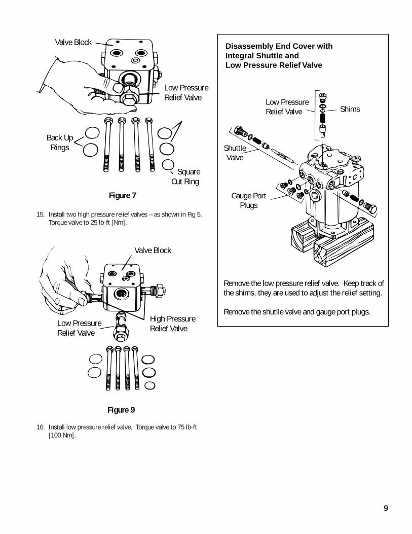
15. Install two high pressure relief valves – as shown in Fig 5.Torque valve to 25 lb-ft [Nm].
16. Install low pressure relief valve. Torque valve to 75 lb-ft[100 Nm].
Valve Block
Back UpRings
Low PressureRelief Valve
Square Cut Ring
Figure 7
Low PressureRelief Valve
High PressureRelief Valve
Valve Block
Figure 9
ShimsLow PressureRelief Valve
ShuttleValve
Gauge PortPlugs
Disassembly End Cover withIntegral Shuttle andLow Pressure Relief Valve
Remove the low pressure relief valve. Keep track of the shims, they are used to adjust the relief setting.
Remove the shutlle valve and gauge port plugs.
10
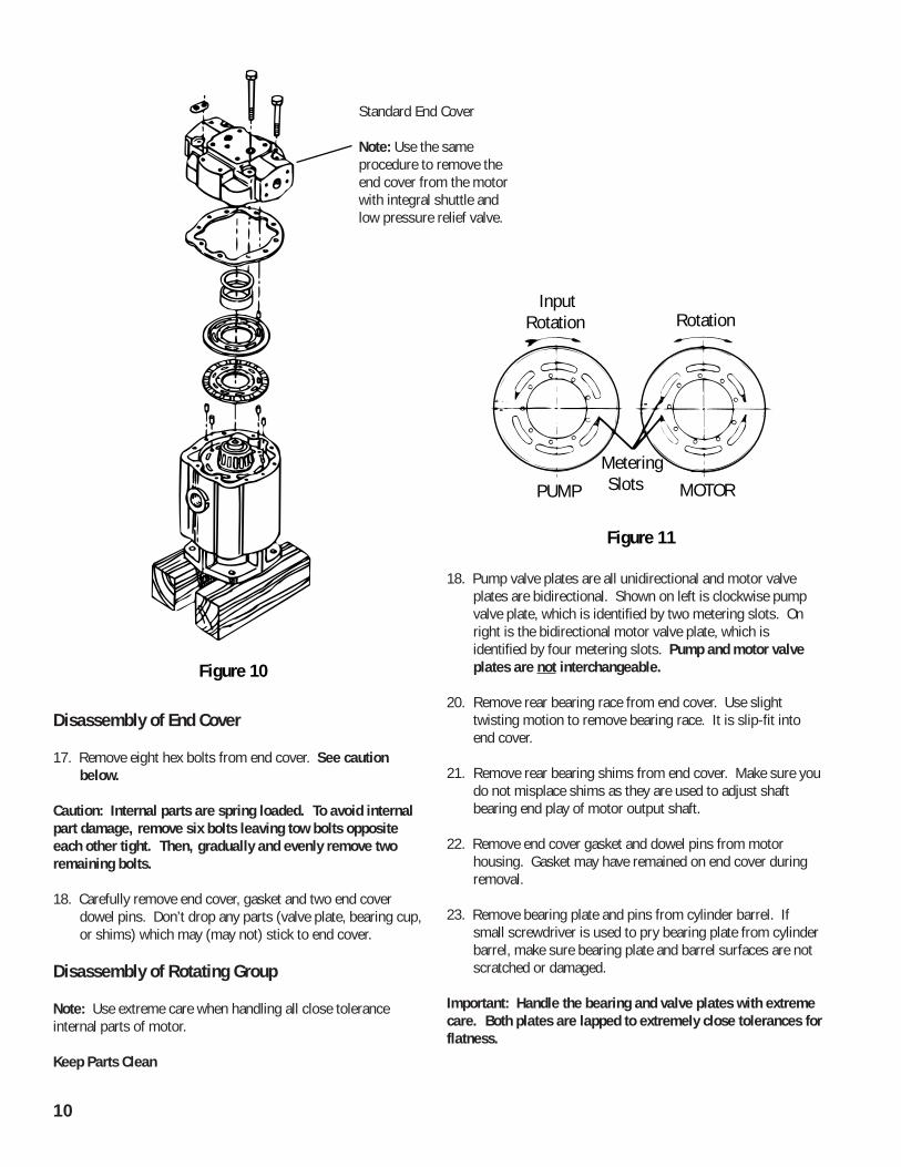
Disassembly of End Cover
17. Remove eight hex bolts from end cover. See cautionbelow.
Caution: Internal parts are spring loaded. To avoid internalpart damage, remove six bolts leaving tow bolts oppositeeach other tight. Then, gradually and evenly remove tworemaining bolts.
18. Carefully remove end cover, gasket and two end coverdowel pins. Don’t drop any parts (valve plate, bearing cup,or shims) which may (may not) stick to end cover.
Disassembly of Rotating Group
Note: Use extreme care when handling all close toleranceinternal parts of motor.
Keep Parts Clean
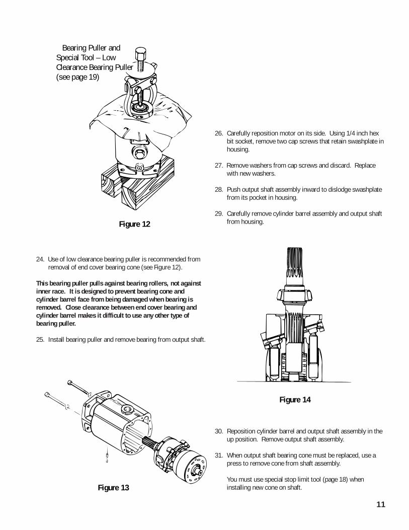
18. Pump valve plates are all unidirectional and motor valveplates are bidirectional. Shown on left is clockwise pumpvalve plate, which is identified by two metering slots. Onright is the bidirectional motor valve plate, which isidentified by four metering slots. Pump and motor valveplates are not interchangeable.
20. Remove rear bearing race from end cover. Use slighttwisting motion to remove bearing race. It is slip-fit intoend cover.
21. Remove rear bearing shims from end cover. Make sure youdo not misplace shims as they are used to adjust shaftbearing end play of motor output shaft.
22. Remove end cover gasket and dowel pins from motorhousing. Gasket may have remained on end cover duringremoval.
23. Remove bearing plate and pins from cylinder barrel. Ifsmall screwdriver is used to pry bearing plate from cylinderbarrel, make sure bearing plate and barrel surfaces are notscratched or damaged.
Important: Handle the bearing and valve plates with extremecare. Both plates are lapped to extremely close tolerances forflatness.
Figure 10
MOTOR
Input Rotation Rotation
PUMP
MeteringSlots
Figure 11
Standard End Cover
Note: Use the sameprocedure to remove theend cover from the motorwith integral shuttle andlow pressure relief valve.
11
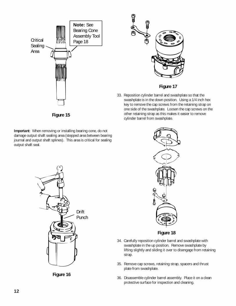
24. Use of low clearance bearing puller is recommended fromremoval of end cover bearing cone (see Figure 12).
This bearing puller pulls against bearing rollers, not againstinner race. It is designed to prevent bearing cone andcylinder barrel face from being damaged when bearing isremoved. Close clearance between end cover bearing andcylinder barrel makes it difficult to use any other type ofbearing puller.
25. Install bearing puller and remove bearing from output shaft.
26. Carefully reposition motor on its side. Using 1/4 inch hexbit socket, remove two cap screws that retain swashplate inhousing.
27. Remove washers from cap screws and discard. Replacewith new washers.
28. Push output shaft assembly inward to dislodge swashplatefrom its pocket in housing.
29. Carefully remove cylinder barrel assembly and output shaftfrom housing.
30. Reposition cylinder barrel and output shaft assembly in theup position. Remove output shaft assembly.
31. When output shaft bearing cone must be replaced, use apress to remove cone from shaft assembly.
You must use special stop limit tool (page 18) wheninstalling new cone on shaft.
Bearing Puller andSpecial Tool – LowClearance Bearing Puller(see page 19)
Figure 12
Figure 13
Figure 14
12
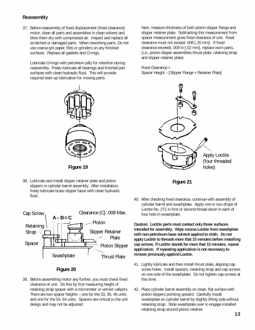
Important: When removing or installing bearing cone, do notdamage output shaft sealing area (stepped area between bearingjournal and output shaft splines). This area is critical for sealingoutput shaft seal.
33. Reposition cylinder barrel and swashplate so that theswashplate is in the down position. Using a 1/4 inch hexkey to remove the cap screws from the retaining strap onone side of the swashplate. Loosen the cap screws on theother retaining strap as this makes it easier to removecylinder barrel from swashplate.
34. Carefully reposition cylinder barrel and swashplate withswashplate in the up position. Remove swashplate bylifting slightly and sliding it over to disengage from retainingstrap.
35. Remove cap screws, retaining strap, spacers and thrustplate from swashplate.
36. Disassemble cylinder barrel assembly. Place it on a cleanprotective surface for inspection and cleaning.
CriticalSealingArea
Note: SeeBearing ConeAssembly ToolPage 18
Figure 15
DriftPunch
Figure 16
Figure 17
Figure 18
13
Reassembly
37. Before reassembly of fixed displacement (fixed clearance)motor, clean all parts and assemblies in clean solvent andblow them dry with compressed air. Inspect and replace allscratched or damaged parts. When reworking parts. Do notuse coarse grit paper, files or grinders on any finishedsurfaces. Replace all gaskets and O-rings.
Lubricate O-rings with petroleum jelly for retention duringreassembly. Freely lubricate all bearings and finished partsurfaces with clean hydraulic fluid. This will providerequired start-up lubrication for moving parts.
38. Lubricate and install slipper retainer plate and pistonslippers in cylinder barrel assembly. After installation,freely lubricate brass slipper faces with clean hydraulicfluid.
39. Before assembling motor any further, you must check fixedclearance of unit. Do this by first measuring height ofretaining strap spacer with a micrometer or vernier calipers.There are two spacer heights – one for the 33, 39, 46 unitsand one for the 54, 64 units. Spacers are critical to the unitdesign and may not be adjusted.
Next, measure thickness of both piston slipper flange andslipper retainer plate. Subtracting this measurement fromspacer measurement gives fixed clearance of unit. Fixedclearance must not exceed .008 [,20 mm]. If fixedclearance exceeds .009 in [,02 mm], replace worn parts,(i.e., piston slipper assemblies thrust plate, retaining strapand slipper retainer plate).
Fixed Clearance =Spacer Height – [Slipper Flange + Retainer Plate]
40. After checking fixed clearance, continue with assembly ofcylinder barrel and swashplate. Apply one or two drops ofLoctite No. 271 in first or second thread down in each offour hole in swashplate.
Caution: Loctite parts must contact only those surfacesintended for assembly. Wipe excess Loctite from swashplatewith non-petroleum base solvent applied to cloth. Do notapply Loctite to threads more that 15 minutes before installingcap screws. If Loctite stands for more that 15 minutes, repeatapplication. If repeating application is not necessary toremove previously applied Loctite.
41. Lightly lubricate and then install thrust plate, aligning capscrew holes. Install spacers, retaining strap and cap screwson one side of the swashplate. Do not tighten cap screws atthis time.
42. Place cylinder barrel assembly on clean, flat surface withpiston slippers pointing upward. Carefully installswashplate on cylinder barrel by slightly lifting side withoutretaining strap. Slide swashplate over to engage installedretaining strap around piston retainer.
Figure 19
Swashplate Thrust Plate
Piston SlipperSpacer
Retaining Strap
Cap Screw Clearance (C) .008 Max.
Piston
Slipper Retainer Plate
Figure 20
A – B = C
Apply Loctite(four threadedholes)
Figure 21
14
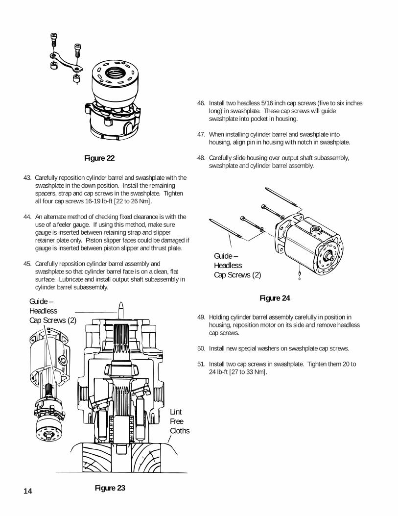
43. Carefully reposition cylinder barrel and swashplate with theswashplate in the down position. Install the remainingspacers, strap and cap screws in the swashplate. Tightenall four cap screws 16-19 lb-ft [22 to 26 Nm].
44. An alternate method of checking fixed clearance is with theuse of a feeler gauge. If using this method, make suregauge is inserted between retaining strap and slipperretainer plate only. Piston slipper faces could be damaged ifgauge is inserted between piston slipper and thrust plate.
45. Carefully reposition cylinder barrel assembly andswashplate so that cylinder barrel face is on a clean, flatsurface. Lubricate and install output shaft subassembly incylinder barrel subassembly.
46. Install two headless 5/16 inch cap screws (five to six incheslong) in swashplate. These cap screws will guideswashplate into pocket in housing.
47. When installing cylinder barrel and swashplate intohousing, align pin in housing with notch in swashplate.
48. Carefully slide housing over output shaft subassembly,swashplate and cylinder barrel assembly.
49. Holding cylinder barrel assembly carefully in position inhousing, reposition motor on its side and remove headlesscap screws.
50. Install new special washers on swashplate cap screws.
51. Install two cap screws in swashplate. Tighten them 20 to24 lb-ft [27 to 33 Nm].
Figure 22
Figure 23
Guide –HeadlessCap Screws (2)
Lint FreeCloths
Guide –Headless Cap Screws (2)
Figure 24
15
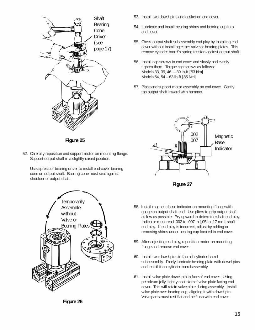
52. Carefully reposition and support motor on mounting flange.Support output shaft in a slightly raised position.
Use a press or bearing driver to install end cover bearingcone on output shaft. Bearing cone must seat againstshoulder of output shaft.
53. Install two dowel pins and gasket on end cover.
54. Lubricate and install bearing shims and bearing cup intoend cover.
55. Check output shaft subassembly end play by installing endcover without installing either valve or bearing plates. Thisremove cylinder barrel’s spring tension against output shaft.
56. Install cap screws in end cover and slowly and evenlytighten them. Torque cap screws as follows:Models 33, 39, 46 – 39 lb-ft [53 Nm]Models 54, 54 – 63 lb-ft [85 Nm]
57. Place and support motor assembly on end cover. Gentlytap output shaft inward with hammer.
58. Install magnetic base indicator on mounting flange withgauge on output shaft end. Use pliers to grip output shaftas low as possible. Pry upward to determine shaft end play.Indicator must read .002 to .007 in [,05 to ,17 mm] shaftend play. If end play is incorrect, adjust by adding orremoving shims under bearing cup located in end cover.
59. After adjusting end play, reposition motor on mountingflange and remove end cover.
60. Install two dowel pins in face of cylinder barrelsubassembly. Freely lubricate bearing plate with dowel pinsand install it on cylinder barrel assembly.
61. Install valve plate dowel pin in face of end cover. Usingpetroleum jelly, lightly coat side of valve plate facing endcover. This will retain valve plate during assembly. Installvalve plate over bearing cup, aligning it with dowel pin.Valve parts must rest flat and be flush with end cover.
Shaft BearingConeDriver(seepage 17)
Figure 25
TemporarilyAssemblewithoutValve orBearing Plates
Figure 26
.002
.007MagneticBase Indicator
Figure 27
16
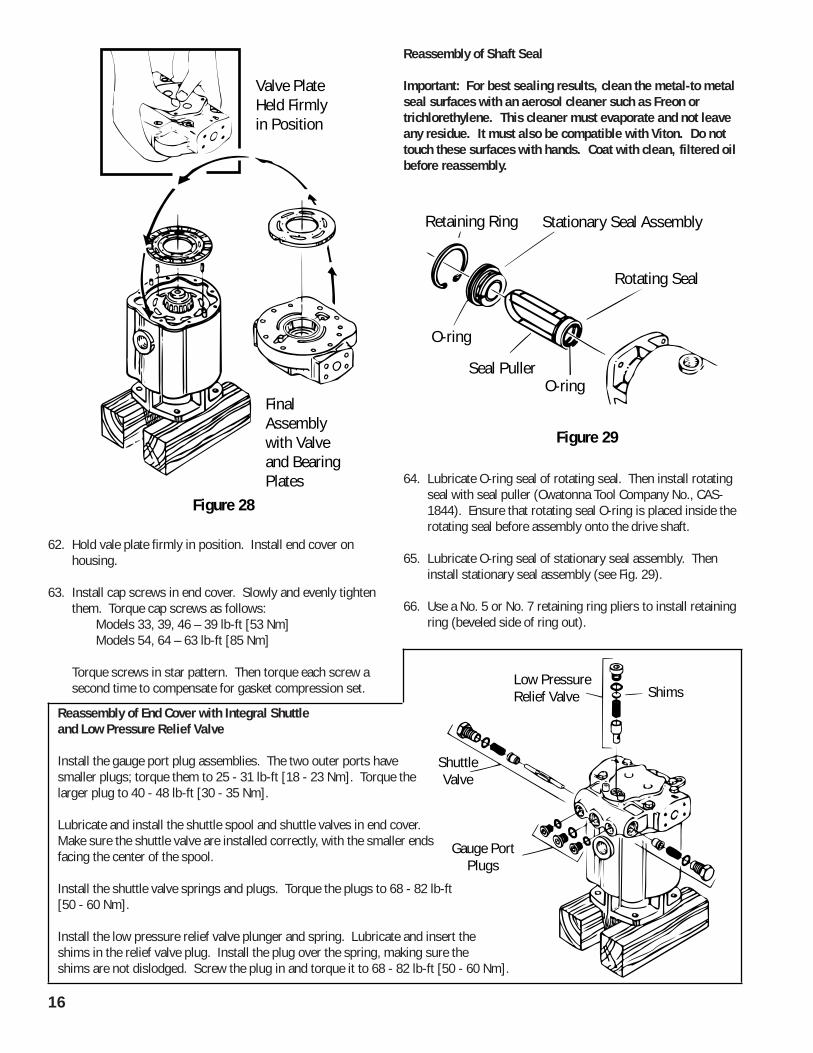
62. Hold vale plate firmly in position. Install end cover onhousing.
63. Install cap screws in end cover. Slowly and evenly tightenthem. Torque cap screws as follows:
Models 33, 39, 46 – 39 lb-ft [53 Nm]Models 54, 64 – 63 lb-ft [85 Nm]
Torque screws in star pattern. Then torque each screw asecond time to compensate for gasket compression set.
Reassembly of Shaft Seal
Important: For best sealing results, clean the metal-to metalseal surfaces with an aerosol cleaner such as Freon ortrichlorethylene. This cleaner must evaporate and not leaveany residue. It must also be compatible with Viton. Do nottouch these surfaces with hands. Coat with clean, filtered oilbefore reassembly.
64. Lubricate O-ring seal of rotating seal. Then install rotatingseal with seal puller (Owatonna Tool Company No., CAS-1844). Ensure that rotating seal O-ring is placed inside therotating seal before assembly onto the drive shaft.
65. Lubricate O-ring seal of stationary seal assembly. Theninstall stationary seal assembly (see Fig. 29).
66. Use a No. 5 or No. 7 retaining ring pliers to install retainingring (beveled side of ring out).
Valve PlateHeld Firmly in Position
FinalAssemblywith Valveand BearingPlates
Figure 28
Retaining Ring
Rotating Seal
Stationary Seal Assembly
Seal PullerO-ring
O-ring
Figure 29
Reassembly of End Cover with Integral Shuttleand Low Pressure Relief Valve
Install the gauge port plug assemblies. The two outer ports havesmaller plugs; torque them to 25 - 31 lb-ft [18 - 23 Nm]. Torque thelarger plug to 40 - 48 lb-ft [30 - 35 Nm].
Lubricate and install the shuttle spool and shuttle valves in end cover.Make sure the shuttle valve are installed correctly, with the smaller endsfacing the center of the spool.
Install the shuttle valve springs and plugs. Torque the plugs to 68 - 82 lb-ft[50 - 60 Nm].
Install the low pressure relief valve plunger and spring. Lubricate and insert theshims in the relief valve plug. Install the plug over the spring, making sure theshims are not dislodged. Screw the plug in and torque it to 68 - 82 lb-ft [50 - 60 Nm].
ShimsLow PressureRelief Valve
ShuttleValve
Gauge PortPlugs
17
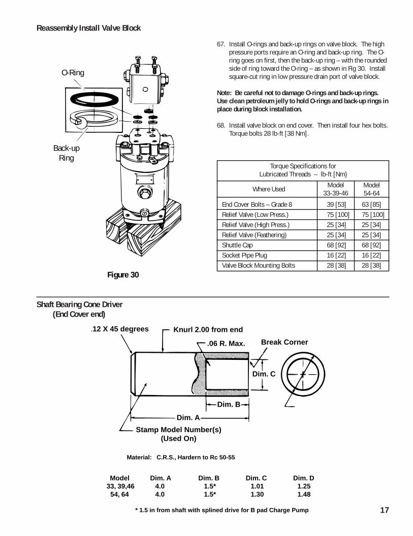
67. Install O-rings and back-up rings on valve block. The highpressure ports require an O-ring and back-up ring. The O-ring goes on first, then the back-up ring – with the roundedside of ring toward the O-ring – as shown in Fig 30. Installsquare-cut ring in low pressure drain port of valve block.
Note: Be careful not to damage O-rings and back-up rings.Use clean petroleum jelly to hold O-rings and back-up rings inplace during block installation.
68. Install valve block on end cover. Then install four hex bolts.Torque bolts 28 lb-ft [38 Nm].
Torque Specifications forLubricated Threads – lb-ft [Nm}
Where Used Model33-39-46
Model54-64
End Cover Bolts – Grade 8 39 [53] 63 [85]Relief Valve (Low Press.) 75 [100] 75 [100]Relief Valve (High Press.) 25 [34] 25 [34]Relief Valve (Feathering) 25 [34] 25 [34]Shuttle Cap 68 [92] 68 [92]Socket Pipe Plug 16 [22] 16 [22]Valve Block Mounting Bolts 28 [38] 28 [38]
Shaft Bearing Cone Driver (End Cover end)
Reassembly Install Valve Block
Back-upRing
O-Ring
Figure 30
.12 X 45 degrees Knurl 2.00 from end
Stamp Model Number(s)(Used On)
.06 R. Max. Break Corner
Dim. C
Dim. B
Material: C.R.S., Hardern to Rc 50-55
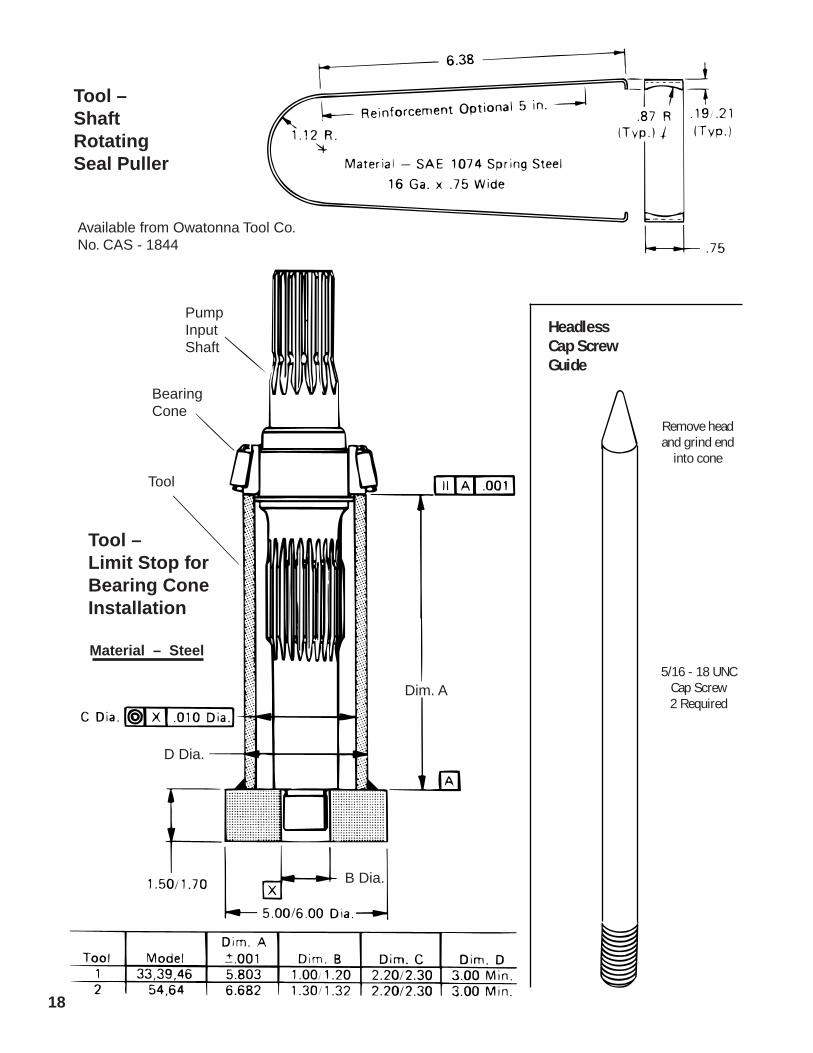
Model Dim. A Dim. B Dim. C Dim. D33, 39,46 4.0 1.5* 1.01 1.25 54, 64 4.0 1.5* 1.30 1.48
* 1.5 in from shaft with splined drive for B pad Charge Pump
Dim. A
18
HeadlessCap ScrewGuide
5/16 - 18 UNCCap Screw2 Required
Remove headand grind end
into cone
Tool –Shaft RotatingSeal Puller
Tool –Limit Stop forBearing ConeInstallation
Available from Owatonna Tool Co.No. CAS - 1844
Material – Steel
Pump InputShaft
BearingCone
Tool
Dim. A
B Dia.
D Dia.

19
Low Clearance Bearing Puller
3/8-16 UNC - 26 Threadas shown 2 places
NOTE: Grind Bore to Size AfterSplitting and Heat Treatment
Model Number...........Etched on this Facein 1/8 in. High Letters
Stentor / 45 - 55 R
Cone Bearing Puller
Material/ Heat Treat
Title
c
Hydrostatic Fluid RecommendationsA reputable supplier can help you make the best selection of hydraulic fluid for use inEaton hydrostatic products.
For satisfactory operation, the following recommendations apply:
• The filter system used in the hydraulic circuit must be capable of maintaining thefluid at ISO Cleanliness Code 18/13 per SAE J1165. This code allows a maximum of2500 particles per milliliter greater than 5µm and a maximum of 80 particles permilliliter greater than 15µm.
• At normal operating temperatures, optimum viscosity ranges are from 80–180 SUS[16–39 cSt]. Viscosity should never fall below 60 SUS [10cSt] and, at the lowestexpected startup temperature, should not exceed 10,000 SUS [2158 cSt].
• The fluid should contain anti-wear agents, rust inhibitors, and anti-foaming agents.
Note: If the fluid becomes black or milky, an overheating or water contaminationproblem exists.
Take fluid level readings when the fluid is cold.

© 2008 Eaton CorporationAll Rights ReservedPrinted in USADocument No. E-MOPI-TS009-ESupersedes 07-127November 2008
EatonFluid Power GroupHydraulics Business USA14615 Lone Oak RoadEden Prairie, MN 55344USATel: 952-937-9800Fax: 952-294-7722www.eaton.com/hydraulics
EatonFluid Power GroupHydraulics Business EuropeRoute de la Longeraie 71110 MorgesSwitzerlandTel: +41 (0) 21 811 4600Fax: +41 (0) 21 811 4601
EatonFluid Power GroupHydraulics Business Asia Pacific 11th Floor Hong Kong New World Tower 300 Huaihai Zhong Road Shanghai 200021 China Tel: 86-21-6387-9988 Fax: 86-21-6335-3912