hydraulic systems - claas industrietechnik · series can be used with all pump systems: ... each...
TRANSCRIPT

CL06
Hydraulic SystemsProduct CatalogueValve Series

CLAAS Industrietechnik 4
Valve Series CL06 Overview 5
Components 6
General technical data 6
Components CL06 Inlet sections 8
Valve sections 14
Secondary valves 21
End sections 26
Modular mobile hydraulic system 30
Contents
All the technical information listed here has been defined using standards or the manufacturer’s testing procedures. Subject to deviations under the customer’s specific operating conditions. We only accept liability for the warranted properties if these properties have been agreed in writing, separately to the factory catalogues. We do not accept liability for the overall function of the plant or machine when supplying individual components.
54 Valve Series CL06
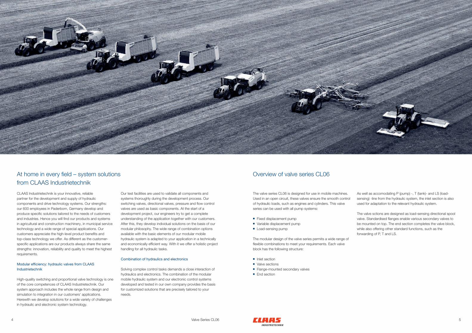
The valve series CL06 is designed for use in mobile machines. Used in an open circuit, these valves ensure the smooth control of hydraulic loads, such as engines and cylinders. This valve series can be used with all pump systems:
■ Fixed displacement pump ■ Variable displacement pump ■ Load-sensing pump
The modular design of the valve series permits a wide range of flexible combinations to meet your requirements. Each valve block has the following structure:
■ Inlet section ■ Valve sections ■ Flange-mounted secondary valves ■ End section
As well as accomodating P (pump) -, T (tank)- and LS (load-sensing) -line from the hydraulic system, the inlet section is also used for adaptation to the relevant hydraulic system.
The valve sctions are designed as load-sensing directional spool valve. Standardised flanges enable various secondary valves to be mounted on top. The end section completes the valve block, while also offering other standard functions, such as the forwarding of P, T and LS.
Overview of valve series CL06
CLAAS Industrietechnik is your innovative, reliable partner for the development and supply of hydraulic components and drive technology systems. Our strengths: our 600 employees in Paderborn, Germany develop and produce specific solutions tailored to the needs of customers and industries. Hence you will find our products and systems in agricultural and construction machinery, in municipal service technology and a wide range of special applications. Our customers appreciate the high-level product benefits and top-class technology we offer. As different as the customer-specific applications are our products always share the same strengths: innovation, reliability and quality to meet the highest requirements.
Modular efficiency: hydraulic valves from CLAAS Industrietechnik
High-quality switching and proportional valve technology is one of the core competences of CLAAS Industrietechnik. Our system approach includes the whole range from design and simulation to integration in our customers’ applications. Herewith we develop solutions for a wide variety of challenges in hydraulic and electronic system technology.
Our test facilities are used to validate all components and systems thoroughly during the development process. Our switching valves, directional valves, pressure and flow control valves are used as basic components. At the start of a development project, our engineers try to get a complete understanding of the application together with our customers. After this, they develop individual solutions on the basis of our modular philosophy. The wide range of combination options available with the basic elements of our modular mobile hydraulic system is adapted to your application in a technically and economically efficient way. With it we offer a holistic project handling for all hydraulic tasks.
Combination of hydraulics and electronics
Solving complex control tasks demands a close interaction of hydraulics and electronics. The combination of the modular mobile hydraulic system and our electronic control systems developed and tested in our own company provides the basis for customized solutions that are precisely tailored to your needs.
At home in every field – system solutions from CLAAS Industrietechnik

76 Valve Series CL06
General technical data
End sectionsPage 26
Secondary valvesPage 21Valve sections,
pilot actuatedPage 18
Inlet sectionsPage 8
Secondary valvesPage 21
Valve sections,direct actuated Page 15
Optimum operating viscosity 35 cSt
Permissible oil types Mineral oil HL, HLP, HVLP according to DIN 51524, other liquids on request
Oil cleanliness ISO 4406: 21/18/14, NAS 1638: Class 9
Seals NBR; others on request
Max. number of sections, that can be flange-mounted 8 per side
Corrosion protection Painted Primer + Top coat 30 µmGalvanized: Coating thickness 8 µm
Installation position Preferably horizontal, other installation positions on request
Ambient temperature – 25° C to +50° C
Input volume flow, max. 140 l/min
Volume at a valve section 90 l/min
Inlet operating pressure, max. 350 bar
Load operating pressure, max. 400 bar
Tank operating pressure, max. 30 bar (210 bar pressure-resistant < 30 min)
Oil temperature -25 °C to +80 °C
Oil viscosity 10 cSt to 500 cSt
Components in valve series CL06

98
LS
P
T
3823
M8
15
9095
120
30
7299
7538
37
30
Inlet sections
Valve Series CL06
General technical data
Operating pressure, max. 350 bar
Port threads according to DIN ISO 6149 -1P: M22 x 1,5T: M27 x 2LS: M14 x 1,5M: M14 x 1,5
Inlet sections
Each valve block starts with an inlet section where the P, T and LS system ports are located to supply the valve block.Together with the end section, the inlet section fastens the entire valve block. The system ports are on one side of the inlet section, while up to eight sectional valves can be flange-mounted on the other side.Valve sections can be attached on both sides in the case of the “Priority” inlet section.
The following inlet sections are available:
■ Standard inlet sections ■ Inlet section with pressure relief valve ■ Open-centre inlet section for fixed displacement pump ■ Closed-centre inlet section for variable displacement pump ■ Priority inlet section
Customized inlet sections are available on request.
Standard inlet section
■ For standard applications ■ P, T and LS connections for supplying the valve block
on the front
Order code EB06 - S - 000 - 000
Series EB06
Standard S
Dimensional drawing and circuit diagram
1110
120 7569
96
100
1763
5643
3780
1520
307580
15.5
4683
2166
2* 1*
M2 T LS M3 P M1
XXX
M8
20.5
54
9095
120 41-48
75
3038
99
2338
15
PTLS
36
78
30
Valve Series CL06
Inlet sections Inlet sections
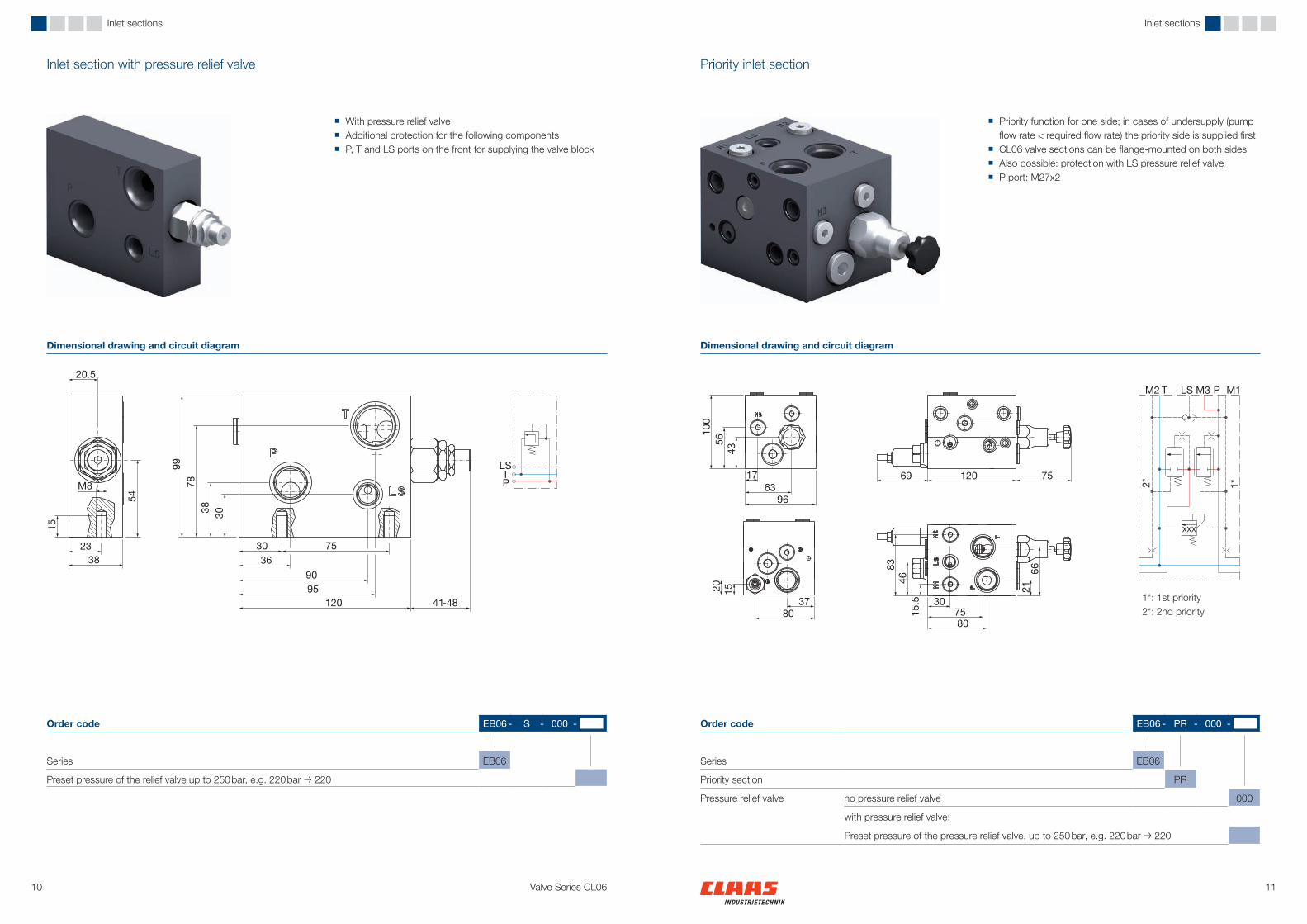
Order code EB06 - PR - 000 -
Series EB06
Priority section PR
Pressure relief valve no pressure relief valve 000
with pressure relief valve:
Preset pressure of the pressure relief valve, up to 250 bar, e.g. 220 bar → 220
Order code EB06 - S - 000 -
Series EB06
Preset pressure of the relief valve up to 250 bar, e.g. 220 bar → 220
Priority inlet sectionInlet section with pressure relief valve
■ Priority function for one side; in cases of undersupply (pump flow rate < required flow rate) the priority side is supplied first
■ CL06 valve sections can be flange-mounted on both sides ■ Also possible: protection with LS pressure relief valve ■ P port: M27x2
■ With pressure relief valve ■ Additional protection for the following components ■ P, T and LS ports on the front for supplying the valve block
Dimensional drawing and circuit diagram Dimensional drawing and circuit diagram
1*: 1st priority2*: 2nd priority
1312
M8
15
M8
15
10
10
M
T
PLS
M
T
PLS
369095120 75
69
283672
100
753028.037.549.064.0
28.0
20
3446
3695
0
50
100
150
200
250
300
0 25 50 75 100 125 150
02468
101214161820
0 25 50 75 100 125 150
Valve Series CL06
Inlet sections Inlet sections
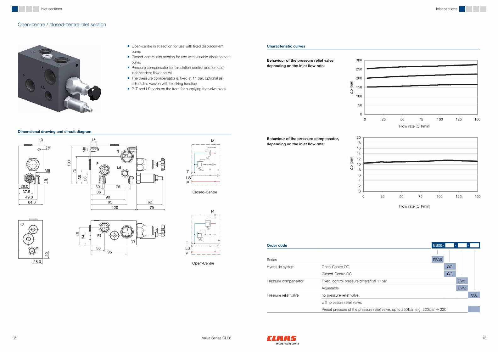
Open-centre / closed-centre inlet section
■ Open-centre inlet section for use with fixed displacement pump
■ Closed-centre inlet section for use with variable displacement pump
■ Pressure compensator for circulation control and for load-independent flow control
■ The pressure compensator is fixed at 11 bar, optional as adjustable version with blocking function
■ P, T and LS ports on the front for supplying the valve block
Dimensional drawing and circuit diagram
Characteristic curves
Closed-Centre
Open-Centre
Order code EB06 - - -
Series EB06
Hydraulic system Open-Centre OC OC
Closed-Centre CC CC
Pressure compensator Fixed, control pressure differential 11 bar DW1
Adjustable DW2
Pressure relief valve no pressure relief valve 000
with pressure relief valve:
Preset pressure of the pressure relief valve, up to 250 bar, e.g. 220 bar → 220
Behaviour of the pressure relief valve depending on the inlet flow rate:
Behaviour of the pressure compensator, depending on the inlet flow rate:
∆p [b
ar]
Flow rate [Q, l/min]
∆p [b
ar]
Flow rate [Q, l/min]

1514
Valve sections
Valve Series CL06
Valve section, direct actuated
■ Switching or proportional ■ Switching solenoid or proportional solenoid with manual
override. This ensures the operation of the valve section, even if the electrical control fails.
Technical data
Series Directional spool valve Direction of flow P → A / B →T; P → B / A →TCentre position open; closed Max. operating pressure pump side
load side350 bar400 bar
Working ports A, B M18 x 1,5 according to DIN ISO 6149-1
Spool size 10, 15, 20, 25, 30, 35, 40 l/min (switching 60 l/min)
Hysteresis ± 10 %, based on nominal value with proportional actuation
Control pressure differential min. 7– 8 barInternal leakage < 60 cm³/min at a load pressure
of 100 bar (HLP46 at 40° C)Nominal currentPower supply 12 V 10 – 40 l/min 0 … 1,9 APower supply 24 V 10 – 40 l/min 0 … 0,95 ANominal power consumption 34 WNominal voltage 12/24 V DCProtection class IP 65Connector type DIN 43650
DT04-2P-EP04AMP-Junior-Timer
Duty cycle 100 %PWM frequency 100 … 150 Hz;
recommended 130 Hz
Tolerance of the nominal flow rate
Nominal flow rate Tolerance10 l/min ± 2 l/min15 l/min ± 2,5 l/min20 l/min ± 3 l/min25 l/min ± 3,5 l/min30 l/min ± 4 l/min35 l/min ± 4 l/min40 l/min ± 4 l/min
Nominal flow rate
The flow rate at working ports A and B can be set in the factory in increments of 20 % of the nominal volumetric flow. This means, for example, that different cylinder movement speeds can be achieved.
The valve sections are the core of a valve block. They are designed in a way that several primary functions are accommodated in the same housing in front of the spool valve.The shuttle valve for the LS chain is located between two mounted valve sections.For additional functions secondary valves can be flanged on.
The following valve sections are available:
■ direct actuated ■ pilot actuated
Valve sections

1716
72 120264
101
48
40
55
99*
LS T P
0
5
10
15
20
25
30
35
40
0 10 20 30 40 50 60
10 15
20
25
30
35
A -> TB -> T
Valve Series CL06
Valve sections Valve sections
Dimensional drawing and circuit diagram
Characteristic curves
*: with secondary valve
Characteristic curve for flow rate at 12 V:
Pressure loss A/B -> T:
∆p [b
ar]
Flow rate [Q, l/min]
Order code CL06 - EM - - - - - - -
Series CL06
Control Electromagnetic EM
Actuation Switching, SW 1
Proportional 2
Spool type
43A
43C
43D
33E
33F
42G
42H
32I
32J
Nominal flow rate Nominal flow rate for sides A and B (e.g. side A 12 l/min and side B 20 l/min → 1220)
Primary function No primary function –
Check valve RV
Pressure compensator DW
Connector type DIN 43650 DIN
DT04-2P-EP04 DT
AMP-Junior-Timer AMP
Nominal voltage 12 V 12
24 V 24
Secondary valve - –
Order code for secondary valve, see components of secondary valves
1918
120 93
265
101
22
76
99*
40
48.0
LS T P
0
5
10
15
20
25
30
35
40
0 10 20 30 40 50 60 70 80 90 100
20 30
40 50
60
A -> TB -> T
∆p [b
ar]
Valve Series CL06
Valve sections Valve sections
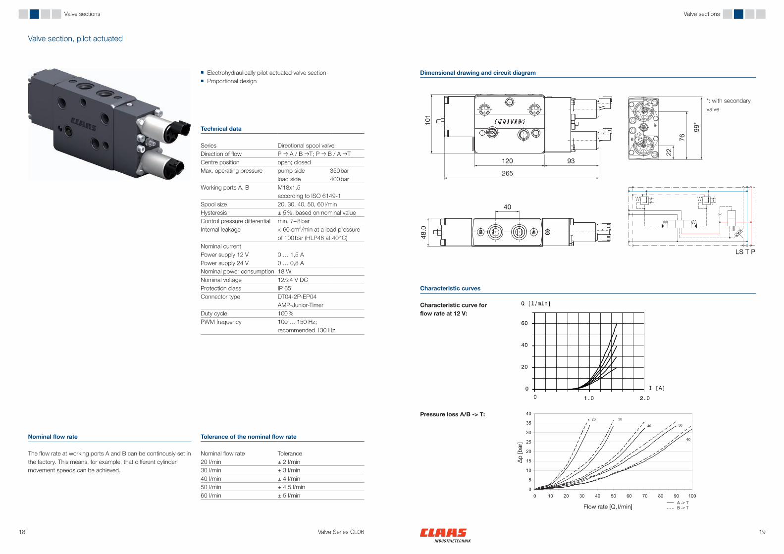
Valve section, pilot actuated
■ Electrohydraulically pilot actuated valve section ■ Proportional design
Technical data
Series Directional spool valve Direction of flow P → A / B →T; P → B / A →TCentre position open; closed Max. operating pressure pump side
load side350 bar400 bar
Working ports A, B M18x1,5 according to ISO 6149-1
Spool size 20, 30, 40, 50, 60 l/minHysteresis ± 5 %, based on nominal valueControl pressure differential min. 7– 8 barInternal leakage < 60 cm³/min at a load pressure
of 100 bar (HLP46 at 40° C)Nominal currentPower supply 12 V 0 … 1,5 APower supply 24 V 0 … 0,8 ANominal power consumption 18 WNominal voltage 12/24 V DCProtection class IP 65Connector type DT04-2P-EP04
AMP-Junior-TimerDuty cycle 100 %PWM frequency 100 … 150 Hz;
recommended 130 Hz
Tolerance of the nominal flow rate
Nominal flow rate Tolerance20 l/min ± 2 l/min30 l/min ± 3 l/min40 l/min ± 4 l/min50 l/min ± 4,5 l/min60 l/min ± 5 l/min
Nominal flow rate
The flow rate at working ports A and B can be continously set in the factory. This means, for example, that different cylinder movement speeds can be achieved.
Dimensional drawing and circuit diagram
*: with secondary valve
Characteristic curves
Characteristic curve for flow rate at 12 V:
Pressure loss A/B -> T:
Flow rate [Q, l/min]
20 21Valve Series CL06
Valve sections
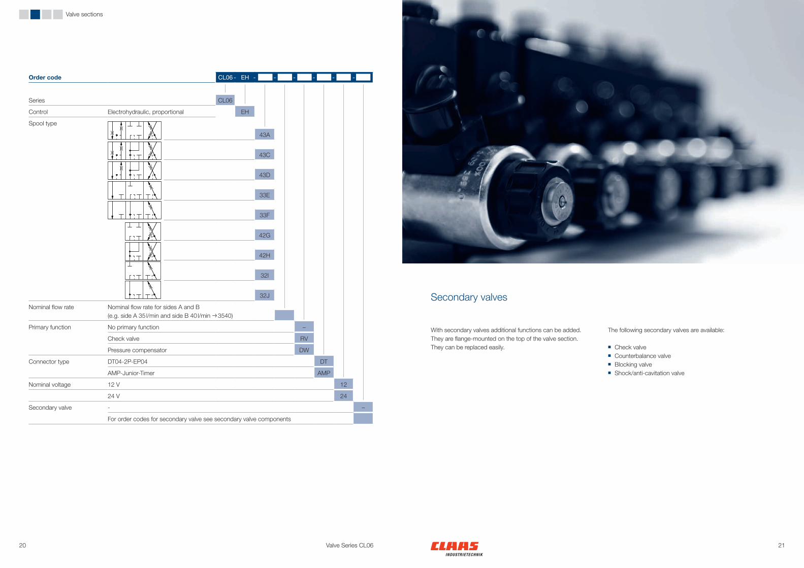
With secondary valves additional functions can be added. They are flange-mounted on the top of the valve section. They can be replaced easily.
The following secondary valves are available:
■ Check valve ■ Counterbalance valve ■ Blocking valve ■ Shock/anti-cavitation valve
Secondary valves
Order code CL06 - EH - - - - - -
Series CL06
Control Electrohydraulic, proportional EH
Spool type
43A
43C
43D
33E
33F
42G
42H
32I
32J
Nominal flow rate Nominal flow rate for sides A and B (e.g. side A 35 l/min and side B 40 l/min → 3540)
Primary function No primary function –
Check valve RV
Pressure compensator DW
Connector type DT04-2P-EP04 DT
AMP-Junior-Timer AMP
Nominal voltage 12 V 12
24 V 24
Secondary valve - –
For order codes for secondary valve see secondary valve components

2322
68
47
120
9039
1*2*
4723
35
61
101 55
47
55101
61
B A
Valve Series CL06
Secondary valves Secondary valves
Order code RV - - - -
Side A No check valve 0
Variant 1 1
Variant 2 2
Side B No check valve 0
Variant 1 1
Variant 2 2
Shock/anti-cavitation valve, side A
None 000
Anti-cavitation only NAS
Shock/anti-cavitation, preset pressure in bar (standard 240 bar)
Shock/anti-cavitation valve, side B
None 000
Anti-cavitation only NAS
Shock/anti-cavitation, preset pressure in bar (standard 240 bar)
Order code SBV - - - -
Side A None 000
Pilot ratio 4:1; Variant 1 S41
Pilot ratio 4,5:1, Variant 2 S45
Side B None 000
Pilot ratio 4:1; Variant 1 S41
Pilot ratio 4,5:1, Variant 2 S45
Side A Preset pressure, up to 350 bar, e.g. 220 bar → 220
Side B Preset pressure, up to 350 bar, e.g. 220 bar → 220
Counterbalance valveCheck valve
■ Controls the movement of loads by regulating the flow rate to and from the actuator
■ Mainly used to lower over-running loads ■ Secure load-holding, setting of the pressure relief valve
to 1.3 times the max. load pressure ■ One-sided and two-sided versions
■ Hydraulically actuated ■ For an oil-tight seal on the load side ■ One-sided or two-sided versions ■ Also used together with shock/anti-cavitation valves SNV
Dimensional drawing and circuit diagram Dimensional drawing and circuit diagram
Variant 1
Variant 21*: Port A2*: Port B
Technical data
Max. operating pressure 350 barPort threads M18 x 1,5; DIN ISO 6149-1Variant 1 / StandardNominal flow rate 40 l/minPilot ratio 3,5:1Pressure drop 4 bar at 40 l/minVariant 2 Nominal flow rate 60 l/minPilot ratio 2,7:1Pressure drop 6 bar at 60 l/min
2,5 bar at 40 l/min
Technical data
Max. operating pressure 350 bar (max. 270 bar load pressure)Variant 1 / StandardPort threads M14 x 1,5; DIN ISO 6149-1Ports on top Nominal flow rate 30 l/minPilot ratio 4:1Pressure drop 7 bar at 20 l/minVariant 2 Port threads M22 x 1,5; DIN ISO 6149-1Ports on the side Nominal flow rate 120 l/minPilot ratio 4,5:1Pressure drop 7 bar at 60 l/min

2524
4723
40120
15 22
1*
2*
93120
47
74.5
62 70
B A
B A
Valve Series CL06
Secondary valves Secondary valves
Order code SNV - -
Shock/anti-cavitation, Side A None 000
Anti-cavitation only NAS
Shock/anti-cavitation, preset pressure in bar (standard 240 bar)
Shock/anti-cavitation, Side B None 000
Anti-cavitation only NAS
Shock/anti-cavitation, preset pressure in bar (standard 240 bar)
Shock/anti-cavitation valveBlocking valve
■ Protects actuator from pressures peaks ■ Suction function prevents cavitation ■ One-sided and two-sided versions ■ Also used together with check valves and blocking valves
(the shock/anti-cavitation valve is integrated in the secondary valve housing of the check valve or blocking valve)
■ Electrically actuated ■ For an oil-tight seal on the load side ■ Without current open or closed ■ Also used together with shock/anti-cavitation valves SNV
Dimensional drawing and circuit diagram Dimensional drawing and circuit diagram
Technical data
Max. operating pressure 350 barPort threads M18x1,5; DIN ISO 6149-1Nominal flow rate 50 l/minPressure drop (closed) 7 bar at 25 l/min
18 bar at 40 l/minPressure drop (open) 5 bar at 25 l/min
12 bar at 40 l/min
Technical data
Max. operating pressure 380 barPort threads M18x1,5; DIN ISO 6149-1Nominal flow rate 60 l/minPressure drop 5 bar at 40 l/min
1*: Valve housing2*: Integrated shock/anti-cavitation valve
Normally closed
Normally open
Order code SV - - - - - -
Side A None 0Normally closed 1Normally open 2
Side B None 0Normally closed 1Normally open 2
Shock/anti-cavitation valve, Side A
None 000Anti-cavitation only NASShock/anti-cavitation, preset pressure in bar (standard 240 bar)
Shock/anti-cavitation valve, Side B
None 000Anti-cavitation only NASShock/anti-cavitation, preset pressure in bar (standard 240 bar)
Connector type DIN 43650 DINDT04-2P-EP04 DTAMP-Junior-Timer AMP
Nominal voltage 12 V 12
24 V 24

2726
1560
107
1055
10
3075
14.5
100
M8
LSTP
End sections
Valve Series CL06
Standard end section
■ For standard applications
Note: LS pressure relief must be provided at an other location in the system
Dimensional drawing and circuit diagram
Together with the inlet section the end section fastens the valve block. Inlet and end section are used for mounting the valve block.
The following end sections are available:
■ Standard ■ LS pressure relief ■ External ports
End sections Valve side
Order code EP06 - S
Series EP06
Standard S

2928
1590120
3588
326075
1517
4260
87107
M8
15
24.5
10
100
LSTP
1560
107
M8
15
3075120
3588100
7.25
7.5
89
14.5
3075120
1560
107110
3588
M8
15
7.5
14.57.5
100
PTLS
LSTP
Valve Series CL06
End sections End sections
End section with external portsEnd section with LS pressure relief
■ LS pressure relief ■ Additional ports
P (M18x1,5), T (M18x1,5) und LS (M14x1,5)
■ LS pressure relief, direct actuated LS1 ■ LS pressure relief, pilot actuated LS2
Dimensional drawing and circuit diagram Dimensional drawing and circuit diagram
Order code EP06 - W
Series EP06
External ports W
Order code EP06 -
Series EP06
LS pressure relief direct actuated LS1
pilot actuated LS2
Valve side
Variant LS1
Variant LS2
Ventilseite
Ventilseite

3130 Valve Series CL06
The modular mobile hydraulic system is characterised by the combination of different valve series in a single valve block:
■ CL06 proportional valves ■ CL04 und CL02 directional cartridge valves ■ ND50 low pressure valves
The valve sections are flanged on a central inlet block, e.g. CL06 on the left side and CL04 on the right side. Special adapter sections also enable various valve series to be connected together directly. The possibility of connecting individual valve sections means that all customer-specific functions can be realized in just one valve block.
Modular mobile hydraulic system – individual control block
Up to 8 valve sections from one series or if combined with special adaptors from different series can be flanged together.
Customer-spezific valve block with standard components CL04
Inlet section,modular mobile hydraulic system or customer-spezific version
CL06 standard valve sections
CL04 standard valve sections
Up to 8 valve sections from one series or if combined with special adaptors from different series can be flanged together.

CLaaS Industrietechnik GmbHHalberstädter Str. 15–1933106 PaderbornGermanyPhone +49(0)5251 [email protected]