rendering in 3d - cloud object storage | store & retrieve … · 554_9781118880364-bc2.indd...
TRANSCRIPT

BC35
BONUS CHAPTER
2 Rendering in 3D
IN THIS CHAPTER
Using rendering to fine-tune your results
Creating realistic lights and scenes
Creating and attaching materials
Rendering your drawing
Although 3D drawings are more realistic than those that you create in 2D, they look very artificial — they lack realistic color (materiality), shading, and lighting, for example. Rendering enables you to display a 3D drawing more realistically. Some of the more advanced features let you create shad-
ows, make objects transparent, add backgrounds, and map 2D images onto the surface of 3D models. You can shade and render 3D objects. Figure B2.1 shows a whimsical rendering that uses shadows and a background.
FIGURE B2.1
This cog has been rendered with shadows and a background of clouds.
54_9781118880364-BC2.indd BC3554_9781118880364-BC2.indd BC35 8/6/2014 12:27:59 PM8/6/2014 12:27:59 PM

BC36
Rendering in 3D
AUTOCAD ONLY AutoCAD LT does not offer any rendering features. This entire chapter applies only to AutoCAD.
This entire chapter assumes that you’re in the 3D Modeling (not the 3D Basics) workspace. Change the workspace with the Workspace Switching button on the status bar.
Understanding Rendering Rendering is a much more sophisticated means of visualizing a model than using visual styles. AutoCAD offers many settings that allow you to fine-tune the results.
Learning the steps Rendering is a multistep process. It generally requires a good deal of trial and error to get the exact results that you want. Here are the steps to render a drawing:
1 . Start with trial rendering by using the default settings. The results let you know what set-tings need to be changed.
2 . Create lights. AutoCAD has seven types of lights. We explain lights in the “ Creating Lights ” section later in this chapter.
3 . Create materials. Materials are surface characteristics and include color and/or texture, reflection (shininess), transparency, refraction, and bump maps. These characteristics are explained later in this chapter in the “ Working with Materials ” section.
4 . Attach materials to the objects in your drawing. You can attach materials by face, object, or layer. ➟ See Chapter 24 for information on how to attach a material to the face of a solid by using the SOLIDEDIT
command.
5 . Add a background or fog effect. We discuss these effects in the “ Using backgrounds ” sec-tion later in this chapter.
6 . Fine-tune your rendering preferences, if desired. For example, you can render with a vari-ety of output qualities.
7 . Render the drawing.
The order of the steps is flexible. For example, you can create and attach materials before you add lights. Also, after you render, you’ll probably see some room for improvement, so you may go back and make changes.
54_9781118880364-BC2.indd BC3654_9781118880364-BC2.indd BC36 8/6/2014 12:28:05 PM8/6/2014 12:28:05 PM

BC37
Rendering in 3D
B O N U S
2
Doing a default rendering Doing a default rendering often helps you to decide what materials and lights you need to create
for your final rendering. It also reveals any problems with the models themselves. To render a drawing with the default settings, choose Visualize tab ➪ Render panel ➪ Render drop-down menu ➪ Render.
One way to get a quick rendering is to choose Visualize tab ➪ Render panel ➪ Render drop-down menu ➪ Render Region, which executes the RENDERCROP command. You define a window, and the command does a default rendering within the area that you define.
TIP Choose Visualize tab ➪ Render panel and click the dialog box launcher at the right end of the panel’s title bar (the RPREF
command). In the Advanced Render Settings palette, Render Context section, use the Procedure field to choose Crop (the
RENDERCROP command just mentioned) or Selected, to render just selected objects. You can also use the Destination field
to render in the current viewport rather than in the default separate Render window. These settings enable you to create
quick draft renderings as you test lights and materials.
By default, the Autodesk Medium Image Library isn’t installed with AutoCAD. If you plan to use the Autodesk Materials library when rendering, you should install the Autodesk Medium Image Library. This library contains a set of images that are of a higher resolution and quality than those that are installed by default. Using the additional image library will improve the quality of a ren-dering, but the tradeoff is an increase in rendering time. You can download the image library by going to the Autodesk website and doing a search on “Autodesk Medium Image Library.” If you render a model that contains materials from the Autodesk Material library without the image library being installed, you will be prompted to install the image library or to continue rendering the model with only the standard image library.
Rendering a complex model can be a time-consuming process and tie up your workstation for min-utes or even hours. AutoCAD allows you to upload your current drawing to the Autodesk Online Rendering Service. The Autodesk Online Rendering Service utilizes cloud computing so that your rendering is done faster and without unnecessarily tying up your workstation. When uploading the drawing, you specify which view to render and an optional e-mail is sent to your inbox once the rendering has been completed. A notification balloon is also displayed when the rendering has been completed. To access the Autodesk Online Rendering Service, choose Visualize tab ➪ Autodesk 360 panel ➪ Render in Cloud. The Render Gallery (Visualize tab ➪ Autodesk 360 panel ➪ Render Gallery) allows you to view past renderings that were generated from your drawings using the Autodesk Online Rendering Service.
ON THE WEB The drawing that you need for the following exercise on creating a default rendering, abb2-a.dwg , is available from the
Drawings download on the companion website.
54_9781118880364-BC2.indd BC3754_9781118880364-BC2.indd BC37 8/6/2014 12:28:05 PM8/6/2014 12:28:05 PM

BC38
Rendering in 3D
STEPS: Creating a Default Rendering
1 . Open abb2-a.dwg , available from the Drawings download on the companion website.
2 . Save the file as abb2-01.dwg in your AutoCAD Bible folder.
3 . Choose Visualize tab ➪ Render panel ➪ Render drop-down menu ➪ Render. Watch as the Render window opens and renders the drawing.
4 . If the Autodesk Materials Library message is displayed, click Work without Using the Medium Images Library. (Click Install the Medium Images Library to download and install the image library if you plan to do high-quality renders of your models, or click Get More Information to visit the Autodesk website and learn more about the image library.)
5 . Save your drawing. It should look like Figure B2.2 . As you can see, the rendering is too dark and the objects need realistic materials.
FIGURE B2.2
An initial rendering, using default options and a crop window
Thanks to Andrew Wilcox of Virtual Homes, Inc., Hammonds Plains, Nova Scotia, Canada, for this drawing.
Creating Lights When you render using the default options, AutoCAD uses default lighting that includes two light sources that fall on the objects in the view. However, default lighting is rarely enough, nor is it realis-tic. AutoCAD offers four types of lights to give you a great deal of flexibility in creating a realistic scene. If you plan to cast shadows in your rendering, the proper placement of lights is most important.
54_9781118880364-BC2.indd BC3854_9781118880364-BC2.indd BC38 8/6/2014 12:28:05 PM8/6/2014 12:28:05 PM

BC39
Rendering in 3D
B O N U S
2
NOTE
The default lighting uses two lights that you must turn off to use the lights that you create. When you create a new
light, AutoCAD displays a message asking if you want to turn off the default lighting. You can also choose Visualize
tab ➪ Lights panel (expanded) ➪ Default Lighting to turn default lighting on and off.
To create lights, choose one of the options from the Visualize tab ➪ Lights panel ➪ Lights drop-down menu, or use the command line. (Several of the lights are available only from the command line.) If you execute the LIGHT command on the command line or in the Dynamic Input tooltip, you can choose one of the seven options to specify which type of light you want to create.
NOTE AutoCAD offers precise photometry settings for lighting, including the ability to set light intensity using real-world values,
such as candela, lumen, or lux. You can also choose the type of lighting ( lamp color ), such as fluorescent, halogen, or
incandescent. To use the photometry feature, you need to set the LIGHTINGUNITS system variable to 1 or 2. A value of 1
enables photometric lighting with American lighting units, and a value of 2 enables it with International lighting units. Set
the value of the LIGHTINGUNITS system variable in the Lighting section of the Drawing Units dialog box (Application
Button ➪ Drawing Utilities ➪ Units), or choose Visualize tab ➪ Lights panel (expanded) ➪ Lighting Units drop-down list and
choose one of the options.
Setting the default light The default lighting consists of two lights that uniformly light up the model from all directions. You can control brightness and contrast by using the sliders in the Visualize tab ➪ Lights panel (expanded). If you have enabled photometric lighting by setting the lighting units of a drawing to American or International, the Midtones slider is available in addition to the Brightness and Contrast sliders. Remember that turning on your own lights turns off the default lighting.
TIP Choose Visualize tab ➪ Render panel (expanded) ➪ Adjust Exposure (the RENDEREXPOSURE command) to open the Adjust
Rendered Exposure dialog box, where you can control brightness, contrast, mid tones, exterior daylight, and processing of
the background. This dialog box does a mini-rendering as you change the values, so that you can see their effect in real
time. Lighting units must be set to American or International before the Adjust Rendered Exposure dialog box can be
displayed.
Creating a point light A point light is equivalent to a typical light bulb or a candle. Light originates from a specific loca-tion and radiates in all directions. A point light attenuates, meaning that the intensity lessens as the distance away from the light’s source increases.
To create a new point light, choose Visualize tab ➪ Lights panel ➪ Create Light drop-down menu ➪ Point. At the Specify source location <0,0,0>: prompt, specify the location of the light.
54_9781118880364-BC2.indd BC3954_9781118880364-BC2.indd BC39 8/6/2014 12:28:05 PM8/6/2014 12:28:05 PM

BC40
Rendering in 3D
Use object snaps to specify the position of your lights. If there are no objects available, work out the position in advance and place an easily visible point object there; you can then snap to the point object by using the Node object snap. Other options are to type the absolute coordinates or use the From object snap to specify a coordinate, based on an existing geometric point on the model.
If you set the XY coordinates in plan view, be sure to set the proper Z coordinate as well. In an architectural drawing, you rarely want your lights to be coming from the floor! However, in a mechanical drawing, it might be appropriate to light your model from any angle.
NOTE If you create an opaque lampshade and place a light inside it, light will get out only through the top and bottom. If you want
light to filter through the lampshade, make it partially transparent. For more information, see “ Working with Materials ” later
in this chapter.
The next prompt depends on the value of the LIGHTINGUNITS system variable, as follows:
• If the value is generic (0), you see the Enter an option to change [Name/Intensity/ Status/shadoW/Attenuation/Color/eXit] <eXit>: prompt.
• If the value is American (1) or International (2), you see the Enter an option to change [Name/Intensity factor/Status/Photometry/shadoW/Attenuation/filterColor/eXit] <eXit>: prompt.
These options are discussed in the next several sections. After you create the light, you can edit these settings in the Properties palette. When you finish specifying the light’s properties, press Enter to exit the command and place the point light.
Name
When you create a light, a default name is automatically created — for example, Pointlight1. Use the Name option to change the name. At the Enter light name <Pointlight1>: prompt, enter a name. You then return to the options prompt. Press Enter to exit the command.
If you change the name, use a name that makes it clear that the light is a point light. Keep the name short; a simple sequence of P1, P2 is often sufficient. However, you could also use P-overhead and P-door or something similar.
Intensity/Intensity factor
Use the Intensity or Intensity factor option to set the intensity, or brightness, of the light. At the Enter intensity (0.00 - max float) <current>: prompt, enter a number. The default is 1; higher numbers make the light brighter. Note that you can also set the brightness by using the Photometry option if you are not using Generic lighting units.
Status
The Status option turns the light on and off. Choose either the oN or oFf option. You can turn lights on and off to create day and night scenes or to experiment with different lighting arrange-ments without having to delete or move lights.
54_9781118880364-BC2.indd BC4054_9781118880364-BC2.indd BC40 8/6/2014 12:28:05 PM8/6/2014 12:28:05 PM

BC41
Rendering in 3D
B O N U S
2
Photometry
If photometry is enabled (lighting units are set to American or International), use this option to specify the intensity and color of the light. There are two suboptions:
• Intensity. You can enter the intensity in candela (abbreviated as cd) units, or you can specify flux, the perceived power of the light, or illuminance, the total flux on a surface area. You can specify illuminance in lux (abbreviated as lx) or footcandle (fc) units.
• Color. You can enter a color name or a Kelvin temperature value. Use the ? option and then press Enter to see a list of names, such as Fluorescent, Coolwhite, Halogen, and others. (Press F2 to expand the Command Line interface or open the AutoCAD Text window, because the names scroll by too fast to see on the command line.)
Shadow
Shadows add greatly to the realism of your rendered image. They also add significantly to the ren-dering time. The Shadow option turns shadows on and off for that light and specifies the type of shadow. If you choose to create shadows, you can choose three types of shadows:
• Sharp. These are sometimes called ray-traced shadows. Use these shadows to reduce ren-dering time.
• Soft Mapped. Enter a map size from 64 to 4,096. Larger map sizes are more accurate but take longer to render. At the Enter softness (1-10) <current>: prompt, enter a number from 1 to 10. The shadow softness determines the number of pixels at the edge of the shadow that are blended into the rest of the image, thus creating the soft effect.
• Soft Sampled. Creates a penumbra (partial shadow) effect. You can specify values for three suboptions:
■ Shape. Specify the shape of the shadow and its dimensions. You can choose from Linear, Disk, Rect (rectangle), Sphere, and Cylinder. Then enter a distance or radius at the prompt to specify the size of the shadow.
■ sAmples. Specify a shadow sample size. The default is 16. A larger sampling size pro-duces a more accurate shadow.
■ Visible. You can choose whether to make the shape you used for the shadow visible in the drawing. Choose Yes or No (the default). If you choose Yes, you see the shape around the light in the rendering.
TIP Because shadows add to rendering time, for your practice renderings while you’re creating lights and materials, turn shad-
ows off in the Advanced Render Settings palette (RPREF command). Scroll down to the Shadows section and click the Light
bulb icon to toggle shadows on and off. When you’re satisfied with the other settings, turn shadows on.
NOTE The 3DCONFIG command includes a Full-shadow Display suboption that allows you to turn shadows off. Also, the automatic
adaptive degradation may affect shadows if your system is not powerful enough. For more information on hardware acceler-
ation and graphics performance, see Appendix A.
54_9781118880364-BC2.indd BC4154_9781118880364-BC2.indd BC41 8/6/2014 12:28:05 PM8/6/2014 12:28:05 PM

BC42
Rendering in 3D
Attenuation
The Attenuation option sets the attenuation, which is the manner in which the light loses intensity as the distance from its source increases. The Attenuation Type suboption offers three choices:
• None. The light doesn’t lose intensity.
• Inverse Linear. The light loses intensity in a linear manner, so that at 2 units from its source the light is half as intense, and at 4 units away the light is one quarter as intense.
• Inverse Squared. The light loses intensity at the square of the distance, so that at 2 units from its source the light is one quarter as intense and at 4 units away the light is one six-teenth as intense. Setting the attenuation to inverse square means that the intensity of the light drops off very quickly.
You can improve your rendering time by setting a limit beyond which there is no light. After a cer-tain distance, it may make no difference if there is a little or no light, and limiting the light to that difference reduces the required calculations. Set the Use Limits suboption to On if you want to use limits. Then set the Attenuation Start Limit and Attenuation End Limit values. The default start limit is 0 (zero). The end limit is a distance from the center of the light.
NOTE The software acceleration driver doesn’t support the use of attenuation start and end limits in the drawing window, but
hardware acceleration does support attenuation end limits.
Color/Filter Color
You can give your light any color you want. Light colors are somewhat different from pigment col-ors, which are more familiar. The three primary light colors are red, green, and blue (RGB). Their mixtures are different, as well; for example, red and green make yellow. White light is the sum of all colors of light together. Black is the absence of any colors of light.
Rather than the RGB light color system, you can use the HLS (hue, lightness, saturation) system. Instead of mixing primary colors, you choose the color from a range of hues and then vary its lightness (brightness) and saturation (intensity).
When you use the Color option, you get the Enter true color (R,G,B) or enter an option [Index color/Hsl/colorBook] <255,255,255>: prompt.
• To enter RGB numbers, enter numbers from 0 to 255 for red, green, and blue. The default, 255,255,255, is white.
• To enter an ACI (AutoCAD Color Index) number, use the Index color suboption and enter a number from 1 to 255. These are the same numbers that you find on the Index Color tab of the Select Color dialog box.
• To use the HSL system, use the Hsl option and then enter an HSL color, which is also three numbers from 0 to 255.
• To specify a color-book color, use the colorBook option.
54_9781118880364-BC2.indd BC4254_9781118880364-BC2.indd BC42 8/6/2014 12:28:05 PM8/6/2014 12:28:05 PM

BC43
Rendering in 3D
B O N U S
2
TIP An easier way to assign a light color is to place the light without changing the color, select the light, and change the color in
the Properties palette. When you choose Select Color from the Color drop-down list of the Properties palette, the Select
Color dialog box opens, where you can see the color swatches for each color. (See Chapter 11 for a discussion of specifying
colors and using color books.)
Specifying a target point light A target point light is like a point light, but you specify a target. This helps you control the direc-tion of the light, making it easier to change a point light to a spotlight. To create a target point light, enter targetpoint on the command line or at the Dynamic Input tooltip. At the Specify source location <0,0,0>: prompt, enter the source of the light. At the Specify target location <0,0,-10>: prompt, specify the target. By default, the target is 10 units less in the Z direction than the source. The rest of the prompts are the same as for a point light. You can change the source and target locations using the Properties palette after a light is placed.
Creating a spotlight A spotlight differs from a point light in that it has a direction. As a result, you not only specify its location but also its target — two coordinates rather than one. In addition, a spotlight has a brighter center called the hotspot. Outside the center is a ring of lesser brightness called the falloff. Figure B2.3 shows the same scene used previously in this chapter, but with one overhead spotlight.
FIGURE B2.3
A rendering with one spotlight overhead. Here the hotspot angle is 45° and the falloff angle is 70°.
54_9781118880364-BC2.indd BC4354_9781118880364-BC2.indd BC43 8/6/2014 12:28:05 PM8/6/2014 12:28:05 PM

BC44
Rendering in 3D
To create a new spotlight, choose Visualize tab ➪ Lights panel ➪ Create Light drop-down menu ➪ Spot. At the Specify source location <0,0,0>: prompt, enter the spotlight’s location. In most cases, you don’t want the Z value to be 0 (zero). At the Specify target location <0,0,-10>: prompt, specify the light’s target.
The prompt that you now see depends on the value of the LIGHTINGUNITS system variable (dis-cussed earlier in this chapter), which turns the photometry feature on and off:
• If the value is generic (0), you see the Enter an option to change [Name/Intensity/Status/Hotspot/Falloff/shadoW/Attenuation/Color/eXit] <eXit>: prompt.
• If the value is American (1) or International (2), you see the Enter an option to change [Name/Intensity factor/Status/Photometry/Hotspot/Falloff/shadoW/Attenuation/filterColor/eXit]
<eXit>: prompt.
All these options are the same as for a point light, except the Hotspot and Falloff options. (See the earlier section, “Creating a point light,” for details.)
Using Weblights
Photometric weblights provide a representation of the way a light’s intensity varies in 3D space. You would use a weblight when you have data about the way a real light’s intensity is distributed. The result is a very precise rendering of the effect of the light. However, this result is only approximate in the viewport.
In order to use weblights, you need to turn on the photometry feature by setting the value of the LIGHTINGUNITS system variable to 1 or 2. For more information on LIGHTINGUNITS, see “ Creating Lights ” earlier in this chapter.
You can insert weblights into your drawing by using the following commands:
• Weblight. Choose Visualize tab ➪ Lights panel ➪ Create Light drop-down menu ➪ Weblight. A web-light is similar to a spotlight, because it requires a target. The options are the same as spotlights, except for an added Web option, which replaces the Hotspot and Falloff options.
• Freeweb. Type freeweb ↵ on the command line or at the Dynamic Input tooltip. A freeweb light is simi-lar to a point light, because it has only a source location. The options are the same as point lights, except for an added Web option.
The Web option lets you specify a file that contains light distribution information at various directions from the light in the IES (Illuminating Engineering Society) LM-63-1991 format. IES is a text-file format for describ-ing this type of information. Light manufacturers provide these IES files (sometimes called photometric data) for their lights. You can also specify individual X, Y, and Z data for the light.
After you place a weblight, you can select it and use the Web File item in the Properties palette to load an IES file. By default, these web files are in the Web Files folder. To find the exact location, choose Application Button ➪ Options and click the Files tab. Double-click the Web File Search Path item. You can change that location or add additional locations.
54_9781118880364-BC2.indd BC4454_9781118880364-BC2.indd BC44 8/6/2014 12:28:06 PM8/6/2014 12:28:06 PM

BC45
Rendering in 3D
B O N U S
2
Set the hotspot and falloff angles for the spotlight. These angles emanate from the spotlight in the direction of the light’s target. The maximum angle for both is 160 degrees. If the hotspot and falloff angles are the same, there is no falloff — the entire spotlight is bright. The defaults are 44 degrees for the hotspot and 50 degrees for the falloff. This doesn’t leave very much falloff area. You may need to experiment to get the desired result. When you’re done creating the spotlight, press Enter to exit the command.
Creating a Free spotlight A free spotlight is like a spotlight, but it has no target. From this perspective, it’s like a point light, but it has a hotspot and falloff, like a spotlight. To create a free spotlight, enter freespot on the command line or at the Dynamic Input tooltip. At the Specify source location <0,0,0>: prompt, enter the location for the light. The rest of the prompts are the same as for a spotlight.
Producing a distant light A distant light is similar to the sun. Its rays come from so far away that, for all practical purposes, they’re parallel. A distant light doesn’t attenuate (unless you’re drawing a model on Pluto). Before inserting a distant light, it is recommended that you set the LIGHTINGUNITS system variable to 0 to turn off the photometric units, or lower the distant light’s intensity.
To create a new distant light, choose Visualize tab ➪ Lights panel ➪ Create Light drop-down menu ➪ Distant. At the Specify light direction FROM <0,0,0> or [Vector]: prompt, specify the source of the light. At the Specify light direction TO <1,1,1>: prompt, specify the light direction. You can specify a point or use the vector system that we discuss in Chapter 22 . If you use the Vector option, you only set the direction of the light. AutoCAD places the light out-side the model, and there is no light glyph. The rest of the options are the same as for creating a point light, which we discuss earlier in this chapter. When you are finished specifying the light, press Enter to exit the command.
Simulating the sun You can simulate the sun by specifying a geographic location for your model and setting specific properties for the sun. In this way, you can get very realistic lighting. When you use the sun tools, you are creating a special type of distant light.
Setting the geographic location
To set the geographic location, choose Visualize tab ➪ Sun & Location panel (expanded) ➪ Set Location. You can then choose to import location information from KML or KMZ files, from Microsoft Bing Maps, or to enter location values manually. If you choose the latter two, the Geographic Location dialog box opens, as shown in Figure B2.4 . (We also discuss this command briefly in Chapter 22 .) The Bing Map data is updated when the drawing is open and connection to the Internet is established. The mapping data stored in a drawing is referred to as Live Map Data .
54_9781118880364-BC2.indd BC4554_9781118880364-BC2.indd BC45 8/6/2014 12:28:06 PM8/6/2014 12:28:06 PM

BC46
Rendering in 3D
FIGURE B2.4
Use the Geographic Location dialog box to specify the latitude and longitude for a specific location.
To specify the location, follow these steps in the Geographic Location dialog box:
1 . Sign into your Autodesk 360 account or close the Sign In dialog box to manually enter values. You must be logged into Autodesk 360 to use Bing Maps.
2 . When signed in, click Use Maps to load Bing Maps and specify a location based on a street address. In the Address text box, type an address (or latitude and longitude values), and press Enter or click Search. If the location is found, click Drop Marker Here. If the exact location was not found or an exact location is not needed, right-click the map and choose Drop Marker Here. Position the cursor over the pin, and click and drag it to repo-sition it on the map.
54_9781118880364-BC2.indd BC4654_9781118880364-BC2.indd BC46 8/6/2014 12:28:06 PM8/6/2014 12:28:06 PM

BC47
Rendering in 3D
B O N U S
2
TIP Use the Zoom and Navigation controls in the upper-right corner of the map to reposition the map in the dialog box. Click
and drag the map to reposition it, or scroll the wheel on the mouse to zoom in and out.
3 . When not signed in, type the latitude, longitude, and elevation of the location you want to use near the bottom of the dialog box.
4 . Click Next to continue.
5 . In the GIS Coordinate System list, choose the coordinate system to assign to the drawing. The GIS Coordinate System list places the best matches for the location specified at the top of the list.
6 . Choose a time zone from the Time Zone drop-down list. The default value is set based on the location specified.
NOTE The time zone automatically adjusts to the location you chose. However, you can separately set the time zone by using the
Time Zone drop-down list or the TIMEZONE system variable.
7 . Choose the drawing unit to use from the Drawing Unit drop-down list. Click Next.
8 . Specify the point in the drawing that represents the pin on the map, and set the North direction of the drawing.
When signed into Autodesk 360 and a geographic location is specified in the drawing, the map is loaded into the current viewport. You can use the tools on the Geolocation tab of the ribbon to control the display of the position marker in the drawing and how the map data appears. Use the tools of the Online Map panel to control whether the map data is displayed in the background of the drawing and the type of imagery to be displayed for the map.
NEW FEATURE In AutoCAD 2014, map data was available for reference only and couldn’t be displayed when outputting a drawing. With
AutoCAD 2015, you can use the GEOMAPIMAGE command to create a Geomap image based on a defined area or the cur-
rent viewport. The Geomap image is an image capture of the map data that can be displayed as part of a drawing’s output.
To adjust the appearance of a Geomap image, select it and use the tools that are displayed on the ribbon.
Setting sun properties
To set properties for the sun, such as the date and time, choose Visualize tab ➪ Sun & Location panel and click the dialog box launcher at the right end of the panel’s title bar (the SUNPROPERTIES command) to open the Sun Properties palette, as shown in Figure B2.5 .
54_9781118880364-BC2.indd BC4754_9781118880364-BC2.indd BC47 8/6/2014 12:28:06 PM8/6/2014 12:28:06 PM

BC48
Rendering in 3D
FIGURE B2.5
The Sun Properties palette keeps all the settings for the sun in one place.
The General properties are the same as the options for the POINTLIGHT command. See the section “ Creating a point light ” earlier in this chapter for more details.
The next four sections only appear if you are using photometric lighting (which means that the LIGHTINGUNITS system variable is 1 or 2).
The Sky Properties section allows you to add a background and illumination effect for the sky when you render the drawing. You don’t see any effect in the regular viewport. You can turn the sky off, choose just a sky background effect, or choose both the sky background and the illumina-tion effect. You can add an intensity factor for the sky. The default value is 1. Changing the inten-sity to 2 will significantly brighten your sky.
54_9781118880364-BC2.indd BC4854_9781118880364-BC2.indd BC48 8/6/2014 12:28:06 PM8/6/2014 12:28:06 PM

BC49
Rendering in 3D
B O N U S
2
➟ To specify these sky properties for a background, turn on photometric lighting and create a new named
view. At the bottom of the New View / Shot Properties dialog box, choose the Sun & Sky option. You can
also use the BACKGROUND command to change the background of a viewport without creating a new view.
See Chapter 22 for more details on creating a new view with a background.
The Haze setting creates a scattering effect. The default is 0.0 and the maximum is 15.0. A setting of 15.0 will create an effect of looking through haze.
The Horizon section controls the horizon, which is where the ground meets the sky. In order to see the horizon, you need a viewpoint that shows the horizon. If your viewport is too close to plan view, you won’t see the horizon, because you’ll be looking down instead of outward. You can set the following properties:
• Height. Sets the position of the ground plane relative to the zero value of the Z axis. Set this in real-world units. For example, 24 would be 2 feet high.
• Blur. Creates a blur at the junction between the ground and the sky. You can see this effect in your drawing (not only when you render), especially if the ground color contrasts with the sky color.
• Ground Color. Choose a color for the ground.
The Advanced section includes three “artistic” effects. First, you can choose a night color. You can also turn aerial perspective on. (It’s off by default.) Aerial perspective is a bluing and slight blur-ring effect that creates the impression of distance. Finally, you can set the visibility distance, which is the distance at which 10% haze kicks in, reducing clarity. This setting also gives an impression of distance.
The Sun Disk Appearance section affects only the appearance of the sun, not the overall light. You can see the results of the changes you make here more clearly in the New View / Shot Properties dialog box. The Disk Scale item specifies a scale for the sun disk itself; a value of 1 is normal size. The Glow Intensity item changes the glow around the disk; 1 is the default value. The Disk Intensity value changes the intensity of the sun disk itself; again 1 is the default value.
The Sun Angle Calculator section allows you to enter a date and time and to specify whether you’re using Daylight Savings Time. To change the date, click the Date item, and then click the Ellipsis button. A little calendar opens. Navigate to the desired date and double-click it. The calen-dar closes. Choose a time from the drop-down list. Choose Yes or No from the Daylight Savings drop-down list.
NOTE You can also adjust the date and time using the two sliders found on the Visualize tab’s Sun & Location panel on the ribbon.
The next three settings are not changeable; they’re based on the location you specified in the Geographic Location dialog box (or the values you previously chose for Date, Time, and Daylight Savings in the Sun Angle Calculator section):
• The azimuth is the angle in the XY plane — North is located at 0 degrees. Use a positive angle to move clockwise from North, and a negative angle to move counterclockwise from North. Values can range from –180 to 180. (Both –180 and 180 would represent South.)
54_9781118880364-BC2.indd BC4954_9781118880364-BC2.indd BC49 8/6/2014 12:28:07 PM8/6/2014 12:28:07 PM

BC50
Rendering in 3D
• The altitude is the angle from the XY plane. You can type in angles from –90 to 90. (An altitude of –90 would mean that the light was coming from beneath the model.)
• The source vectors are the coordinates that represent the sun’s direction. For more informa-tion on the vector system, see “Using the VPOINT command” in Chapter 22 .
The Rendered Shadow Details section offers the same settings discussed earlier in the “ Creating a point light ” section. However, when photometric lighting is on, the only shadow choice is Soft (Area), which creates sampled shadows. Shadows need to be on in the General section for these settings to be available.
Managing lights To keep track of and manage your lights, choose Visualize tab ➪ Lights panel and click the dialog
box launcher at the right end of the panel’s title bar (the LIGHTLIST command). The Lights in Model palette is shown in Figure B2.6 .
FIGURE B2.6
The Lights in Model palette lists all your lights.
Lights can be difficult to select; they may be inside a lamp or high up, out of your current display. Distant lights don’t have a glyph that you can click on to select them. The Lights in Model palette helps you select, modify, and delete lights. To select a light, choose it in the palette.
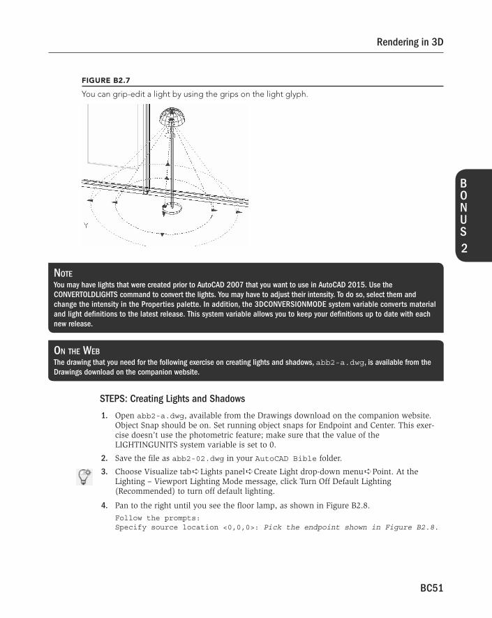
You can now edit the light either with grips or the Properties palette. Figure B2.7 shows a selected spotlight. You can easily change the spotlight’s location, target, hotspot, and falloff by using grips. To change its status (on or off), color, and other properties, use the Properties palette.
To delete a light, choose it in the Lights in Model palette and press the Delete key. You can’t delete the sun, you can only turn it off. (Good night!)
54_9781118880364-BC2.indd BC5054_9781118880364-BC2.indd BC50 8/6/2014 12:28:07 PM8/6/2014 12:28:07 PM
BC51
Rendering in 3D
B O N U S
2
FIGURE B2.7
You can grip-edit a light by using the grips on the light glyph.
NOTE You may have lights that were created prior to AutoCAD 2007 that you want to use in AutoCAD 2015. Use the
CONVERTOLDLIGHTS command to convert the lights. You may have to adjust their intensity. To do so, select them and
change the intensity in the Properties palette. In addition, the 3DCONVERSIONMODE system variable converts material
and light definitions to the latest release. This system variable allows you to keep your definitions up to date with each
new release.
ON THE WEB The drawing that you need for the following exercise on creating lights and shadows, abb2-a.dwg , is available from the
Drawings download on the companion website.
STEPS: Creating Lights and Shadows
1 . Open abb2-a.dwg , available from the Drawings download on the companion website. Object Snap should be on. Set running object snaps for Endpoint and Center. This exer-cise doesn’t use the photometric feature; make sure that the value of the LIGHTINGUNITS system variable is set to 0.
2 . Save the file as abb2-02.dwg in your AutoCAD Bible folder.
3 . Choose Visualize tab ➪ Lights panel ➪ Create Light drop-down menu ➪ Point. At the Lighting – Viewport Lighting Mode message, click Turn Off Default Lighting (Recommended) to turn off default lighting.
4 . Pan to the right until you see the floor lamp, as shown in Figure B2.8 . Follow the prompts: Specify source location <0,0,0>: Pick the endpoint shown in Figure B2.8 .
54_9781118880364-BC2.indd BC5154_9781118880364-BC2.indd BC51 8/6/2014 12:28:07 PM8/6/2014 12:28:07 PM

BC52
Rendering in 3D
Enter an option to change [Name/Intensity/Status/shadoW/Attenuation/Color/eXit] <eXit>: n ↵
Enter light name <Pointlight1>: p1 ↵ Enter an option to change [Name/Intensity/Status/shadoW/Attenuation/
Color/eXit] <eXit>: i ↵ Enter intensity (0.00 - max float) <1.0000>: 3 ↵ Enter an option to change [Name/Intensity/Status/shadoW/Attenuation/
Color/eXit] <eXit>: x ↵
5 . Choose Visualize tab ➪ Lights panel and click the dialog box launcher at the right end of the panel’s title bar. In the Lights in Model palette, click the new p1 light listed there to select the light.
6 . Right-click over the Lights in Model palette and choose Properties. On the Properties pal-ette, click the Filter Color item and choose Yellow from the drop-down list. Click the Shadows item and choose On from the drop-down list (if it’s not already on).
FIGURE B2.8
Picking the point light location
7 . On the Navigation bar, choose Zoom drop-down menu ➪ Zoom Previous to return to your previous view, or type zoom ↵ at the command line or the Dynamic Input tooltip. If you enter the ZOOM command, type p ↵ to use the Previous option.
8 . Choose Visualize tab ➪ Lights panel ➪ Create Light drop-down menu ➪ Spot. Follow the prompts:
Specify source location <0,0,0>: Shift+right-click and choose From from the OSNAP list.
_from Base point: Use the Center object snap of the top edge of the round table.
<Offset>: @0,0,5' ↵ (This places the light 5 feet directly over the table, like a light hanging from the ceiling.)
Specify target location <0,0,-10>: Use the Center object snap of the top of the table.
54_9781118880364-BC2.indd BC5254_9781118880364-BC2.indd BC52 8/6/2014 12:28:07 PM8/6/2014 12:28:07 PM

BC53
Rendering in 3D
B O N U S
2
Point to the edge of the round table. Enter an option to change [Name/Intensity/Status/Hotspot/Falloff/shadoW/Attenuation/Color/eXit]
<eXit>: n ↵ Enter light name <Spotlight1>: s1 ↵ Enter an option to change [Name/Intensity/Status/Hotspot/Falloff/shadoW/Attenuation/Color/eXit]
<eXit>: f ↵ Enter falloff angle (0.00-160.00) <50>: 70 ↵ Enter an option to change [Name/Intensity/Status/Hotspot/Falloff/shadoW/Attenuation/Color/eXit]
<eXit>: h ↵ Enter hotspot angle (0.00-160.00) <3'-9">: 40 ↵ Enter an option to change [Name/Intensity/Status/Hotspot/Falloff/shadoW/Attenuation/Color/eXit]
<eXit>: w ↵ Enter [Off/Sharp/soFtmapped/softsAmpled] <Sharp>: f ↵ Enter map size [64/128/256/512/1024/2048/4096] <256>: 256 ↵ Enter softness (1-10) <1>: 5 ↵ Enter an option to change [Name/Intensity/Status/Hotspot/Falloff/shadoW/Attenuation/Color/eXit]
<eXit>: x ↵
9 . Choose Visualize tab ➪ Sun & Location panel (expanded) ➪ Set Location ➪ From Map. In the Geographic Location – Specify Location dialog box, type 41.00,-91.57 in the Address text box and click Search when logged into Autodesk 360. When not logged into Autodesk 360, set Latitude to 41.00 and Longitude to -91.57, and press Enter. Click Drop Marker Here and then click Next.
10 . In the GIS Coordinate System, choose UTM84-15N. Choose (GMT-06:00) Central Time (US & Canada) from the Time Zone drop-down list if the option is not already set. Set drawing units to Inches. Click Next. Follow the prompts: Select a point for the location < current >: 0,0,0 ↵ Specify the north direction angle or [First point] < current >: 90 ↵
11 . Choose Geolocation tab ➪ Online Map panel ➪ Show Map drop-down menu ➪ Map Off. The map data remains in use, but the image from the map is suppressed.
12 . Choose Visualize tab ➪ Sun & Location panel and click the dialog box launcher at the right end of the panel’s title bar. In the Sun Properties palette, set the date to 9/1 (September 1). Set the time to 8:00 in the morning. (You’re having breakfast.) Set the Daylight Savings item to Yes.
13 . Close the Sun Properties and Lights in Model palettes (or auto-hide them).
14 . Choose Visualize tab ➪ Render panel and click the dialog box launcher at the right end of the panel’s title bar. In the Shadows section of the Advanced Render Settings palette, click the Specifies If Shadows Are Computed light bulb icon, making sure that it is deselected.
15 . Choose Visualize tab ➪ Render panel ➪ Render drop-down menu ➪ Render. Click Work without Using the Medium Images Library in the Autodesk Materials Library – Medium Image Library Not Installed message. The rendering should take less than a minute, and it should look like Figure B2.9 . There is more than enough light this time — but remem-ber, you wouldn’t normally eat breakfast with all the lights on. Notice the effect of the yellow point light; it makes the blue floor and walls look green.
54_9781118880364-BC2.indd BC5354_9781118880364-BC2.indd BC53 8/6/2014 12:28:07 PM8/6/2014 12:28:07 PM

BC54
Rendering in 3D
FIGURE B2.9
A rendering with lights but no shadows
16 . Display the Advanced Render Settings palette again if you closed it. Click the Specifies If Shadows Are Computed light bulb icon in the Shadows section. Click Render. Notice that the rendering takes much longer. Lots of shadows this time! This rendering also makes it clear that no light is coming through the windows. (See the “ Working with Materials ” section to learn how to make materials transparent.) The rendering should look like Figure B2.10 .
17 . Save your drawing. If you’re continuing on to the next exercise, keep this drawing open.
FIGURE B2.10
The same rendering with shadows
54_9781118880364-BC2.indd BC5454_9781118880364-BC2.indd BC54 8/6/2014 12:28:07 PM8/6/2014 12:28:07 PM

BC55
Rendering in 3D
B O N U S
2
Working with Materials Materials in AutoCAD are representations of actual materials on objects, such as glass, metal, fab-ric, wood, and others. Using materials is an important part of the rendering process and greatly affects the results. Materials interact with lights. For example, shiny materials reflect light differ-ently than dull materials because shiny materials create highlights.
You can display materials as you work. Although this requires more resources from your computer, you can see some results immediately, without rendering. Rendering always produces a more accu-rate result. To display materials, choose Visualize tab ➪ Materials panel ➪ Materials/Textures drop-down menu ➪ Materials / Textures On. You need to be in the Realistic visual style (or a custom visual style using the Realistic face style) to see the result.
Attaching a material from the Materials Browser The Materials Browser, as shown in Figure B2.11 , lets you attach and manage materials. To open
the Materials Browser, choose Visualize tab ➪ Materials panel ➪ Materials Browser. The Materials Browser is divided into two areas:
• Document Materials. The upper area of the Materials Browser lists the materials in the current drawing. You can use the Document Materials and Sort drop-down list just above the material swatches to control how the materials in the current drawing are displayed in the Materials Browser.
• Libraries. The lower area of the Materials Browser provides access to materials in the available libraries, including the Autodesk Library and your own material libraries, even one called Favorites.
From the Materials Browser, you can manage the materials in the current drawing by doing the following:
• Create a material. Click the Create Material drop-down list (sphere with a plus sign icon) in the lower-left corner of the Materials Browser and choose a template to create a new material. Choose New Generic Material to give you the most control over the definition of the new material. The Materials Editor palette opens so you can edit the properties of the new material.
• Assign a material to an object. Select the objects you want to apply the material to in the drawing. Right-click a material and choose Add to Selection. Press and hold the Ctrl key if you want to select a face on a 3D solid or mesh, or use subobject filtering (choose Home tab ➪ Selection panel ➪ Subobject Filter drop-down menu ➪ Face). See the section, “ Attaching and removing materials ” for additional information.
• Locate an object that has a material assigned to it. Right-click a material in the Document Materials section and choose Select Objects Applied To. This selects the objects in the drawing that have been assigned the material.
• Edit a material. Right-click a material and choose Edit to display the material in the Materials Editor palette.
• Copy a material. Right-click a material and choose Duplicate to create a duplicate copy of the material with a new name that you can then alter as needed.
• Rename a material. Right-click a material and choose Rename to change the name of the material in the current drawing or material library.
54_9781118880364-BC2.indd BC5554_9781118880364-BC2.indd BC55 8/6/2014 12:28:08 PM8/6/2014 12:28:08 PM

BC56
Rendering in 3D
FIGURE B2.11
The Materials Browser lets you manage materials in the current drawing and those stored in a materials library.
• Remove a material. Right-click a material and choose Delete to remove the material defi-nition from the current drawing or material library.
• Add a material to a library or current tool palette. Right-click a material and choose the appropriate item from the Add To sub-menu.
• Purge all unused materials. Right-click a material in the Document Materials section and choose Purge All Unused to remove the materials currently not assigned to any objects in the drawing.
Besides managing materials in the current drawing, you use the Materials Browser to organize and access materials stored in material libraries. AutoCAD ships with the Autodesk Library of materials. You can see which material libraries are available in the Libraries panel. Double-click
54_9781118880364-BC2.indd BC5654_9781118880364-BC2.indd BC56 8/6/2014 12:28:08 PM8/6/2014 12:28:08 PM

BC57
Rendering in 3D
B O N U S
2
a material library to see the categories contained in the library and select a category to see the materials it contains. You can manage a material library by doing the following:
• Open a material library. Click the Manage drop-down list (folder with a wrench icon) in the lower-left corner of the Materials Browser and choose Open Existing Library. In the Add Library dialog box, browse to and select the material library (ADSKLIB) file that you want to open. Click Open.
• Create a material library. You can create your own material library files, which allows you to easily share and archive your materials. Click the Manage drop-down list (folder with a wrench icon) in the lower-left corner of the Materials Browser and choose Create New Library. In the Create Library dialog box, browse to the location you want to store your material library at and enter a name for the library. Click Save.
• Remove a material library. Expand Home and select a library that is not read-only. Click the Manage drop-down list (folder with a wrench icon) in the lower-left corner of the Materials Browser or right-click a library, and choose Remove Library.
• Create or delete a category. Categories help to organize materials. Select a library from the list that is not read-only. Click the Manage drop-down list (folder with a wrench icon) in the lower-left corner of the Materials Browser or right-click a library, and choose Create Category. Enter a name for the new category and press Enter. Select a category and choose Delete Category to remove the category. In the Content Will Be Deleted message box, click Delete to confirm the deletion of the category and its materials.
• Move materials between categories. Materials can be moved between categories as a way to reorganize them or to keep some materials in a category you might want to delete. To move a material, click and drag the material from one category to another.
• Rename a category. Select a category from a library that is not read-only. Click the Manage drop-down list (folder with a wrench icon) in the lower-left corner of the Materials Browser or right-click the category, and choose Rename. Enter a new name and press Enter.
NOTE You can only edit the materials in the current drawing. If you need to make changes to a material stored in a library, add it
to the current drawing and then edit it. After editing the material, add it to the library to update the old material with the
revised material.
ON THE WEB The drawing that you need for the following exercise on creating a new material library and attaching materials from the
Materials Browser, abb2-02.dwg , is available from the Result download on the companion website.
54_9781118880364-BC2.indd BC5754_9781118880364-BC2.indd BC57 8/6/2014 12:28:08 PM8/6/2014 12:28:08 PM

BC58
Rendering in 3D
STEPS: Creating a New Material Library and Attaching Materials from the Materials
Browser
1 . If you have abb2-02.dwg open, use this file. Otherwise, it’s available from the Result download on the companion website.
2 . Save the file as abb2-03.dwg in your AutoCAD Bible folder.
3 . Choose Visualize tab ➪ Visual Styles panel ➪ Visual Styles drop-down list ➪ Realistic.
4 . Choose Visualize tab ➪ Materials panel ➪ Materials/Textures drop-down menu ➪ Materials / Textures On.
5 . Choose Visualize tab ➪ Materials panel ➪ Materials Browser.
6 . On the Materials Browser, double-click Autodesk Library and choose the Wood category.
7 . In the middle of the Materials Browser, to the right of the text, “Autodesk Library” and “Wood,” click the Sort drop-down list and choose List View under View Type. Position the cursor between the column headers of Name and Type. When you see the double-arrow cursor, double-click to expand the Name column.
8 . Locate the Maple - Stained Dark Polished material.
9 . Select the table object in the drawing and right-click the Maple - Stained Dark Polished material in the Materials Browser. Choose Assign to Selection. The tabletop changes color, but still doesn’t look very much like wood. In the next exercise, you’ll fix that. Click in the drawing window and press Esc to deselect the table.
10 . At the bottom of the Materials Browser, click the Manage drop-down list (folder with a wrench icon) and choose Create New Library.
11 . In the Create Library dialog box, browse to the AutoCAD Bible folder and type My Materials in the File Name text box. Click Save.
12 . Right-click the Maple - Stained Dark Polished material in the Autodesk Library under the Wood category. Choose Add To ➪ My Materials.
13 . Save your drawing. If you’re continuing on to the next exercise, keep this drawing open. TIP If you created a material library in AutoCAD 2011 or later, you can migrate it to AutoCAD 2015 using the Migrate Custom
Settings dialog box. See Appendix A for information on migrating customization from an earlier release to AutoCAD 2015.
Using the Materials Editor palette To manage and modify materials in the current drawing, choose Visualize tab ➪ Materials panel
and click the dialog box launcher at the right end of the panel’s title bar to open the Materials Editor palette (the MATEDITOROPEN command), as shown in Figure B2.12 . You can also right-click a material in the Materials Browser and choose Edit.
54_9781118880364-BC2.indd BC5854_9781118880364-BC2.indd BC58 8/6/2014 12:28:08 PM8/6/2014 12:28:08 PM

BC59
Rendering in 3D
B O N U S
2
FIGURE B2.12
The Materials Editor palette lets you create and edit materials. Note that the properties available vary with the material’s template.
The top section of the Materials Editor palette displays a preview of the material that you are cur-rently editing. To edit a material, open the Materials Browser and select the material to edit.
TIP You can access the properties of a material on a tool palette by right-clicking the material on the Tool Palettes window and
choosing Properties to open a dialog box for that material.
54_9781118880364-BC2.indd BC5954_9781118880364-BC2.indd BC59 8/6/2014 12:28:08 PM8/6/2014 12:28:08 PM

BC60
Rendering in 3D
Creating your own materials To create your own material, click the Create Material drop-down list (sphere with a plus sign
icon) in the lower-left corner of the Materials Browser or Materials Editor palette. Then choose a material template. A new material appears in the Materials Browser and the material is available for editing in the Materials Editor palette.
Note that you can also modify an existing material or copy an existing material and modify that copy from the Materials Browser. In fact, to get the results that you want, you often need to modify an existing material in some way. To copy a material, right-click it in the Materials Browser and choose Duplicate.
You can also click the Create Material drop-down list (sphere with a plus sign icon) in the lower-left corner of the Materials Editor palette, and choose Duplicate to create a copy of the material you are currently editing. The Materials Editor also allows you to choose Duplicate as Generic, which creates a new Generic material from the current material. The Generic material gives you much greater control over the appearance of the material by allowing you to access properties that are normally not exposed using the more specific material templates.
NOTE You may have materials that you created in AutoCAD 2007 and previous releases that you would like to use. You must con-
vert such materials to work with AutoCAD 2015. Use the CONVERTOLDMATERIALS command for this purpose. You may need
to adjust the images and procedural-based textures for the materials by using the Texture Editor palette, as described later
in this section. In addition, the 3DCONVERSIONMODE system variable can convert material and light definitions to the
latest release. This system variable allows you to keep your definitions up to date with each new release.
Choosing a material type
After choosing a template, the next step in creating a material is to choose a material type. Not all material templates allow you to specify a material type. A material type provides you with the abil-ity to refine the material you created based on the original template you choose. For example, if you choose the Plastic template, you can define the type of plastic you want to create using the Type drop-down list; this makes it easy to get the material to look a specific way without worrying about a series of complex properties.
Assigning a material color
The next step is to specify the properties for your new material. The properties available in the Materials Editor palette are determined by the material template you selected when you created the material. Figure B2.13 shows the properties for a material created with the Generic material template.
You assign a color to a material by clicking the color swatch, or clicking the down arrow to the right of the color swatch and choosing Edit Color. The Select Color dialog box opens. Specify the color you want to use for the material and click OK. Some materials allow you to use the color an object is assigned in the drawing for the material. Click the down arrow to the right of a color swatch and choose Color by Object when the option is available. Not all materials support the Color by Object option.
54_9781118880364-BC2.indd BC6054_9781118880364-BC2.indd BC60 8/6/2014 12:28:09 PM8/6/2014 12:28:09 PM

BC61
Rendering in 3D
B O N U S
2
FIGURE B2.13
Use this section of the Materials Editor palette to specify colors and characteristics for your material.
Specifying an image or procedural-based texture
You can further specify an image or procedural-based texture for your material if you need a material that is more than a single color. You commonly change the color or image of a material, not both. A procedural-based texture is a pattern that represents a material like tiles or marble, and is generated by specifying a material template and setting attribute values specific to the template selected. Click the down arrow to the right of the procedural-based texture or image swatch and choose Image to use a raster image file or one of the procedural-based textures listed. Choosing Image displays the Material Editor Open File dialog box, which allows you to select the image file you want to use for the material.
NOTE Procedural-based textures are calculated each time a rendering is created and can improve the quality of the rendered
image at low and high resolutions.
54_9781118880364-BC2.indd BC6154_9781118880364-BC2.indd BC61 8/6/2014 12:28:09 PM8/6/2014 12:28:09 PM
BC62
Rendering in 3D
You can choose one of the following procedural-based textures for your material:
• Checker. Two-color checkerboard pattern
• Gradient. Gradient pattern
• Marble. Marble-like pattern that is defined by stone and vein colors
• Noise. Randomly generated turbulence based on a combination of two colors or textures
• Speckle. Randomly generated speckle pattern
• Tiles. Brick and tile patterns
• Waves. Randomly generated ripple or wave pattern
• Wood. Wood-grain-like pattern that is defined by main and grain colors
After selecting an image file or a procedural-based texture, the Texture Editor palette opens, which allows you to control the appearance of the image or procedural-based texture. Figure B2.14 shows the Texture Editor palette. As you edit the properties in the Texture Editor palette, you can see the material update in real-time in both the Materials Browser and Materials Editor palette.
The Appearance section of the Texture Editor palette allows you to specify the image, colors, and other settings specific to the procedural-based texture you selected in the Materials Editor palette. Use the Transforms section to control the position, scale, and repeat (tiling) of the image or pro cedural-based texture. Check Link Texture Transforms to have all textures of a material update when you make a change to the position, scale, or repeat values for a texture.
To edit an image or procedural-based texture assigned to a material, click the down arrow to the right of the swatches under the Appearance section and choose the desired option. Based on the template you started with, you can remove an assigned image or procedural-based texture by click-ing the down arrow to the right of the swatch and choosing Color.
Choosing properties specific to the material template
You can specify the properties specific to the material you are editing; these vary based on the material’s template. For most materials, you can find these properties below the Color property, almost always in the upper section of the Materials Editor palette. Some examples of these proper-ties are Sealant and Finish Bumps for Concrete, and Finish for Ceramic and Wood materials.
Adding other characteristics to a material
The lower sections of the Materials Editor palette allow you to add additional characteristics to your materials. You add these additional characteristics to a material by clicking the check box next to the ones you want to use. You can then edit the properties in each section. The following are the characteristics that can be added to a Generic material (there are others that are specific to materials such as Wood and Ceramic):
• Reflectivity. Controls the level of reflections and intensity of specular highlights.
• Transparency. Controls the level of transparency of the material. A value of 1 indicates the material is fully transparent, and 0 indicates it is fully opaque.
• Cutouts. Creates perforations in a material. Perforations are determined by grayscale interpre-tation; light areas are translated as opaque, while dark areas are translated as transparent.
54_9781118880364-BC2.indd BC6254_9781118880364-BC2.indd BC62 8/6/2014 12:28:09 PM8/6/2014 12:28:09 PM

BC63
Rendering in 3D
B O N U S
2
FIGURE B2.14
You can define the settings for an image and procedural-based texture.
• Self illumination. Marks an object to appear as if it emits light.
• Bump. Creates the effect of varying heights — bumps — on a material. The image or procedural-based texture is usually black and white.
• Tint. Controls the amount of white that is mixed with the base color of the material.
54_9781118880364-BC2.indd BC6354_9781118880364-BC2.indd BC63 8/6/2014 12:28:09 PM8/6/2014 12:28:09 PM

BC64
Rendering in 3D
NOTE Each of the material characteristics we mentioned in this section affect the way light is rendered on an object.
Adjusting the mapping
The way in which a material, especially one with a texture, maps onto an object may not be suit-able for that object’s shape. For example, mapping a floral pattern onto a flat surface is different from mapping it onto the wall of a cylindrical shape. If the pattern has a direction, you may want to rotate it.
Use the MATERIALMAP command to fine-tune the mapping of a material. Choose Visualize tab ➪ Materials panel ➪ Material Mapping drop-down list, and choose one of the options (Box, Planar, Cylindrical, or Spherical) that best describes the type of surface the material has been applied to. You can then move or rotate the texture, using the Move Grip or Rotate Grip tool.
ON THE WEB The drawing that you need for the following exercise on modifying and creating materials, abb2-03.dwg , is available
from the Result download on the companion website.
STEPS: Modifying and Creating Materials
1 . If you have abb2-03.dwg open from the previous exercise, use this file. Otherwise, open it from your AutoCAD Bible folder (if you did the exercise). It’s also available from the Result download on the companion website.
2 . Save the file as abb2-04.dwg in your AutoCAD Bible folder.
3 . If you can’t see the beige/brown color on the table top, choose Visualize tab ➪ Visual Styles panel ➪ Visual Styles drop-down list ➪ Realistic. Then choose Visualize tab ➪ Materials panel ➪ Materials/Textures drop-down menu ➪ Materials / Textures On.
4 . Choose Visualize tab ➪ Materials panel ➪ Materials Browser to open the Materials Browser. In the Document Materials list, right-click the Maple - Stained Dark Polished material and choose Edit.
5 . In the Materials Editor palette, click the image swatch to open the Texture Editor palette.
6 . In the Texture Editor palette, under the Scale section, enter 5 in the Width text box. This reduces the wood grain by 50 percent, because it tells AutoCAD that the image should be repeated every 5" instead of the default 10".
7 . To create a material for the wedge of cheese on the plate, in the Materials Editor palette, click the Create Material drop-down list (sphere with a plus sign icon) in the lower-left corner and then choose New Generic Material. From the Options drop-down list to the right of the Preview image, choose Cube.
54_9781118880364-BC2.indd BC6454_9781118880364-BC2.indd BC64 8/6/2014 12:28:10 PM8/6/2014 12:28:10 PM

BC65
Rendering in 3D
B O N U S
2
8 . Use the following settings for the new material:
■ Name. Yellow Cheese.
■ Color. Click the color swatch. From the Index Color tab of the Select Color dialog box, choose Color 51, a light yellow. Click OK.
■ Glossiness. Drag the Glossiness slider down to about 20. Cheese isn’t very shiny.
■ Bump. Click the check box next to Bump. In the Material Editor Open File dialog box, click Cancel. Click the down arrow to the right of the Image swatch under the Bump section and choose Noise. In the Texture Editor palette, click in the Size text box and enter 0.5 . Close or auto-hide the Texture Editor and Materials Editor palettes. Don’t close the Materials Browser.
9 . In the drawing window, select the wedge on the plate. In the Materials Browser, right-click the Yellow Cheese material and choose Assign to Selection to attach the Yellow Cheese material.
NOTE You may not be able to see the bump map in your drawing. To see it, choose Visualize tab ➪ Render panel ➪ Render drop-
down menu ➪ Render. By default, the rendering appears in a separate application window. If the Autodesk Materials Library –
Medium Image Library Not Installed message box appears, click Work without Using the Medium Images Library.
10 . Save your drawing.
Attaching and removing materials After you import, create, and modify the materials that you need, you can attach them to objects. AutoCAD lets you attach materials to
• An entire object by selecting the object
• All objects on a specified layer, including layers of objects within a block
• A face on an object (by subselecting the face)
Earlier in this chapter, we discussed how to attach materials from the Materials Browser in the “ Attaching a material from the Materials Browser ” section.
To attach a material to all objects on a layer, you use the MATERIALATTACH command, which you can find by choosing Visualize tab ➪ Materials panel (expanded) ➪ Attach By Layer. The Material Attachment Options dialog box opens, as shown in Figure B2.15 .
Drag any material from the left to a layer on the right to attach the material. To detach a material from a layer, click the Detach button (the X) that appears in the right-hand column.
54_9781118880364-BC2.indd BC6554_9781118880364-BC2.indd BC65 8/6/2014 12:28:10 PM8/6/2014 12:28:10 PM

BC66
Rendering in 3D
FIGURE B2.15
Use the Material Attachment Options dialog box to attach a material to all objects on a layer.
TIP Attaching materials by layer can be a very efficient method, but it requires some planning in advance. For example, if you
have a block that is a chair, you can create it so that the legs are on one layer and the seat and back are on a different
layer; then you can easily attach a wood-like material to the legs and a decorative pattern to the seat and back.
You can remove a material attached to an object by choosing Visualize tab ➪ Materials panel (expanded) ➪ Remove Materials. At the Select objects: prompt, select the object or face.
Using backgrounds You can add a background to a rendering by saving a view that includes a background. In Chapter 22 , we explain how to add a background by using the VIEW command. For example, you can place a picture of the sky in the background (refer to Figure B2.1 in this chapter). You can also use the BACKGROUND command to add a background without first creating a named view.
NOTE Releases of AutoCAD prior to 2007 included a scenes feature that allowed you to save views and light settings. Scenes and
landscape objects (such as trees) are no longer available.
54_9781118880364-BC2.indd BC6654_9781118880364-BC2.indd BC66 8/6/2014 12:28:10 PM8/6/2014 12:28:10 PM

BC67
Rendering in 3D
B O N U S
2
ON THE WEB The files that you need for the following exercise on attaching materials and adding a background, abb2-b.dwg and
bluesky.jpg , are available from the Drawings download on the companion website.
STEPS: Attaching Materials and Adding a Background
1 . Open abb2-b.dwg , available from the Drawings download on the companion website. Download bluesky.jpg from the Drawings download on the companion website to your AutoCAD Bible folder.
2 . Save the file as abb2-05.dwg in your AutoCAD Bible folder. This is the same drawing used earlier in the chapter, but all the materials have been imported and modified, and some materials have been attached to objects. Also, the table and chairs have been sepa-rated into appropriate layers.
3 . If you’re not in the Realistic visual style, choose Visualize tab ➪ Visual Styles panel ➪ Visual Styles drop-down list ➪ Realistic.
4 . Choose Visualize tab ➪ Materials panel (expanded) ➪ Attach By Layer. In the Material Attachment Options dialog box, drag the light wood material from the Material Name list onto the LEGS layer. (To find the layer more easily, click the Layer heading in the right pane to alphabetize the layers.) Then drag the striped fabric material onto the CUSHIONS layer. Click OK.
5 . In the drawing window, select the plate on the table. In the Materials Browser, right-click the GREEN GLASS material and choose Assign to Selection.
6 . Choose Visualize tab ➪ Views panel ➪ View Manager. In the View Manager, click New. In the New View / Shot Properties dialog box’s View Name text box, type Render with background . In the Background section, select Image from the drop-down list. The Background dialog box opens.
7 . Click the Browse button. In the Select File dialog box, you may need to change the Files of Type drop-down list to All Image Files. Select bluesky.jpg (which you copied to your AutoCAD Bible folder in Step 1) and click Open.
Foggy Landscapes
Fog is used to give a sense of distance by making objects in the distance less clear than those close up. To add a fog effect, choose Visualize tab ➪ Render panel (expanded) ➪ Environment to open the Render Environment dialog box. Click the Enable Fog field and then choose On from the drop-down
list. You set the color (a gray color by default), near and far distances (where the fog starts and ends), and near and far percentages of fog (how much fog there should be at the near and far distances). You can also apply the fog to the background (the Fog Background setting), which turns the entire background the color of the fog. To use fog, you need to set front and back clipping on, using the 3DCLIP command. Move the front clip-ping plane in front of the nearest object and the back clipping plane behind the farthest object. You then need to render to see the results; you can’t see them in the drawing viewport.
54_9781118880364-BC2.indd BC6754_9781118880364-BC2.indd BC67 8/6/2014 12:28:10 PM8/6/2014 12:28:10 PM

BC68
Rendering in 3D
8 . In the Background dialog box, click Adjust Image. From the Image Position drop-down list, choose Stretch. You can see how the image improves. Click OK three times to return to the View Manager. Click Set Current and click OK to return to your drawing. You should see the image appear through the windows. (If not, you may need to render the drawing.)
9 . Save your drawing. Keep it open if you’re continuing to the next exercise.
Doing the Final Render You’re finally ready for your final rendering. Preparing to render can be a long process. At this time, you may want to look at some of the more specialized settings for rendering in the Advanced Render Settings palette, as shown in Figure B2.16 . To open the Advanced Render Settings palette (the RPREF command), choose Visualize tab ➪ Render panel and click the dialog box launcher at the right end of the panel’s title bar. Here we highlight some of the more common settings.
FIGURE B2.16
The Advanced Render Settings palette lets you set many rendering options. This figure shows about half of the available settings.
54_9781118880364-BC2.indd BC6854_9781118880364-BC2.indd BC68 8/6/2014 12:28:10 PM8/6/2014 12:28:10 PM

BC69
Rendering in 3D
B O N U S
2
TIP When it comes to rendering, trial and error can often be the best learning technique to understand how various settings
affect the rendered images of your models. In addition to trial and error, you can also learn rendering techniques and meth-
ods that work best for your models by others in the same industry by studying rendered images that other users post online.
At the top of the Advanced Render Settings palette is the drop-down list of the render presets. Render presets are groups of settings that you can use when you don’t want to customize the settings. You can choose from Draft, Low, Medium (the default), High, and Presentation. (You can customize the presets themselves, by choosing Visualize tab ➪ Render panel ➪ Render Presets drop-down list ➪ Manage Render Presets [the RENDERPRESETS command]. You can also use the Render Presents drop-down list on the Render panel to set the current render present.) The choice you make depends on your situation — how much you need to see, whether you’re doing a draft or final rendering, and the capabilities of your computer system, especially its graphics card and memory.
The Render Context section contains settings that relate to the rendering as a whole. This section allows you to choose how your model gets rendered. Here are your options:
• Save File. Click the Determines If File Is Written toggle button if you want to save the resulting rendering to a file. Click the same button to cancel saving to a file.
• Procedure. You can render the current view, crop to a window, or render selected objects.
• Destination. You can render to the current viewport or to a separate window.
• Output File Name. If you chose to save a file, click this item, click the Ellipsis button to navigate to a location, and enter a filename. You can save renderings as BMP, PCX, TGA, TIF, JPG/JPEG, or PNG files.
• Output Size. Choose an output size (in pixels) from the drop-down list or choose Specify Output Size to customize your size settings.
• Exposure Type. Choose Automatic or Logarithmic. Automatic exposure is the default output setting, and is the setting used with releases prior to AutoCAD 2009. The Logarithmic set-ting is useful when you want more control over exposure, but are not using photometric lighting.
• Physical Scale. This setting helps to reduce artifacts (imperfections) caused by changes in exposure. The default value is 1500. If you see artifacts, you need to experiment to find a value that works for you; the best value in a drawing with a sun will be different than in a drawing with just point lights.
TIP From the Render panel, you can also specify if a rendering is saved to a file as well as control its destination and output
size. The Output Size drop-down list is available when you expand the Render panel.
The Materials section has settings relating to materials. You can specify the following:
• Apply Materials. Turns materials on and off.
• Texture Filtering. Samples textures by area to avoid aliasing, which results in artifacts, such as a jagged or moiré effect.
• Force 2-Sided. Renders both sides of faces, even those facing away from the view. You can turn this off to speed up rendering.
54_9781118880364-BC2.indd BC6954_9781118880364-BC2.indd BC69 8/6/2014 12:28:10 PM8/6/2014 12:28:10 PM

BC70
Rendering in 3D
The Sampling section offers settings to control sampling, which is the precision with which the rendering deals with each pixel. A lower minimum sampling rate is quicker but less accurate. A 1/4 sampling rate (the default) makes one calculation for every four pixels. The maximum sam-pling rate applies when the neighboring pixels are different enough (have enough contrast) to require more precise sampling. The default is 1, which is one calculation per pixel. The contrast colors control the contrast values used to determine how much sampling to do, based on the mini-mum and maximum rates.
The Shadows section has a Light bulb toggle button that turns shadows on and off. You can turn shadows off to speed up rendering. The Mode determines the order in which shadows are computed — Simple (randomly), Sorted (from an object to the light), and Segment (along the light ray). Shadow Map turns on shadow mapping. When this is off, shadows are ray-traced, which results in sharper and more accurate outlines. Shadow maps allow for soft shadows. The Sampling Multiplier limits sampling for shadows throughout the drawing. Use this feature to create draft renders. Lower values mean less sampling; higher values produce more accurate results. Values range from 0 to 2.
The Ray Tracing section affects how the renderer calculates ray-traced shadows. The Light bulb toggle button turns ray tracing on and off. The Max Depth setting controls how many reflections and refractions can be calculated. You can also individually set the maximum reflections and refractions that are calculated.
The Indirect Illumination section has three subsections — all relate to subtle light effects in addi-tion to direct lights that you create. These settings control radiosity, the simulation of multiple reflections of light as they interact with each other, to create more natural lighting. For example, Global Illumination creates color bleeding, which occurs when the color of one surface affects the color of a nearby surface. Final Gather adds an additional calculation to eliminate dark corners and other artifacts, but adds greatly to rendering time. The Light Properties section has controls that affect lights that you create when you use indirect illumination. You can increase the accuracy and brightness of lights with these settings, but doing so increases rendering time.
The Diagnostic section helps troubleshoot the rendering results. You can turn on the display of a grid to help understand how the renderer is placing an object. You may have noticed that when you render, the rendering appears tile by tile. You can change the size of this tile, the order of the tiling, and the maximum memory used during the rendering process.
To render, choose Visualize tab ➪ Render panel ➪ Render drop-down menu ➪ Render. The model is rendered according to the settings in the Advanced Render Settings palette, which reflects the set-tings of the current render preset. You can also use the RENDER command on the command line by typing -render ↵.
ON THE WEB The drawing that you need for the following exercise on creating a final rendering, abb2-05.dwg , is available from the
Result download on the companion website.
54_9781118880364-BC2.indd BC7054_9781118880364-BC2.indd BC70 8/6/2014 12:28:10 PM8/6/2014 12:28:10 PM

BC71
Rendering in 3D
B O N U S
2
STEPS: Creating a Final Rendering
1 . If you have abb2-05.dwg open, use this file. Otherwise, open it from your AutoCAD Bible folder if you did the previous exercise, or from the Result download on the com-panion website.
2 . Save the file as abb2-06.dwg in your AutoCAD Bible folder.
3 . Choose Visualize tab ➪ Lights panel and click the dialog box launcher at the right end of the panel’s title bar. In the Lights in Model palette, double-click P1. In the Properties pal-ette, change the light’s Intensity property to 2 and press Enter. This is the type of adjust-ment you often make when doing the final rendering.
4 . Choose Visualize tab ➪ Render panel and click the dialog box launcher at the right end of the panel’s title bar. In the Advanced Render Settings palette, under the Shadows section, change the Shadow Map setting to On. This results in softer shadows. (You can try it both ways to see the difference.)
5 . Choose Visualize tab ➪ Render panel ➪ Render drop-down menu ➪ Render. If the Autodesk Materials Library – Medium Image Library Not Installed message box appears, click Work without Using the Medium Images Library.
6 . The Rendering window should open. Wait until AutoCAD finishes the rendering. Look at those shadows! Can you see the orange in the transparent green bowl? Note the sky image outside the window.
7 . The rendering should look like Figure B2.17 , only a lot better because you see it in color on your screen. Save your drawing.
FIGURE B2.17
The final rendering with shadows, transparent objects, and a background
Remember that rendering is a trial-and-error process. Don’t expect to get it right the first time. You can probably see several areas that require improvement. At this point, you would go back and tweak the lights, materials, and so on until you were satisfied.
54_9781118880364-BC2.indd BC7154_9781118880364-BC2.indd BC71 8/6/2014 12:28:10 PM8/6/2014 12:28:10 PM

BC72
Rendering in 3D
Using Statistics When you render to the render window, the right pane lists a number of statistics relating to your rendering. You can use these statistics to troubleshoot or compare results among renderings. The bottom pane shows your rendering history.
Saving rendered images You can save your rendered images and re-display them at another time. You can also use saved rendered images in other applications and print them from those applications. Here are the steps to saving a rendering to an image file:
1 . Render the image.
■ After rendering to a viewport, on the command line, type saveimg ↵.
■ After rendering to the render window, choose File ➪ Save from that window’s menu.
2 . In the Render Output File dialog box, choose a file type from the File of Type drop-down list. Choose a location and enter a name for the file.
3 . Depending on the image type that you choose, you’ll see a dialog box offering options such as the number of colors and the quality. Choose the options you want and click OK to save the image.
You can import these saved rendered images back into your drawing. Figure B2.18 shows three floating viewports. One of the views shows the rendered image. ➟ See Chapter 26 for detailed instructions on importing images. You can plot rendered viewports, as we
explain in Chapter 17 .
FIGURE B2.18
You can include your rendered images in your drawings.
54_9781118880364-BC2.indd BC7254_9781118880364-BC2.indd BC72 8/6/2014 12:28:11 PM8/6/2014 12:28:11 PM

BC73
Rendering in 3D
B O N U S
2
Summary In this bonus chapter, we covered the process of rendering. You read about the following:
• Creating lights
• Managing, importing, and creating materials
• Attaching materials
• Using backgrounds
• Rendering a drawing
54_9781118880364-BC2.indd BC7354_9781118880364-BC2.indd BC73 8/6/2014 12:28:11 PM8/6/2014 12:28:11 PM

54_9781118880364-BC2.indd BC7454_9781118880364-BC2.indd BC74 8/6/2014 12:28:11 PM8/6/2014 12:28:11 PM