removing and replacing parts: dell inspiron 5000 seriesrtellason.com/manuals/70khu.pdf · removing...
TRANSCRIPT
Removing and Replacing Parts: Dell™ Inspiron™5000 SeriesNOTICE: Only a certified service technician should perform repairs on yourcomputer. Damage or inoperability due to servicing not authorized by Dell isnot covered by your warranty.
Overview LCD Removal
Precautionary Measures Video Board Removal
Recommended Tools Diskette Drive Removal
Customer-AccessibleComponents
Palmrest Removal
Screw Counts and Locations Speaker and Volume BoardRemoval
ZIF Connectors Support Rail Removal
Modem Removal Infrared Board Removal
Hinge Cover Removal System Board Removal
Keyboard Removal 14.1-Inch XGA DisplayDisassembly
Thermal Shield Removal 15-Inch UXGA, XGA, andSXGA+ Display Disassembly
Processor Module Removal
OverviewUnless otherwise noted, each procedure assumes the following:
You have the recommended tools.●
You have performed the steps in Precautionary Measures.●
The computer and any attached peripherals are turned off and the peripherals are disconnected from the input/output(I/O) panel.
●
You can replace or reinstall a part by performing the removal procedure in reverse order unless additional informationis provided.
●
Removing and Replacing Parts: Dell Inspiron 5000 Series
file:///c|/docs/blanco E-doc/removing.htm (1 of 29) [9/1/2000 3:31:59 PM]
Precautionary Measures
NOTICE: Only a certified service technician should perform repairs on yourcomputer. Damage or inoperability due to servicing not authorized by Dell isnot covered by your warranty.
WARNING: FOR YOUR PERSONAL SAFETY ANDPROTECTION OF THE EQUIPMENT:
Before you start to work on the computer, perform the following steps in thesequence indicated:
Ground yourself by attaching an antistatic grounding strap to your wristand to an unpainted metal surface on the computer I/O panel. If anantistatic grounding strap is not available, periodically discharge staticelectricity from your body by touching one of the connectors on the I/Opanel.
1.
Turn off the computer and any attached peripherals.2.
Disconnect the computer and any attached peripherals from electricaloutlets to reduce the potential for personal injury or shock.
3.
Recommended Tools
NOTICE: Only a certified service technician should perform repairs on yourcomputer. Damage or inoperability due to servicing not authorized by Dell isnot covered by your warranty.
Most of the procedures require the use of one or more of the following tools:
Small flat-blade screwdriver●
Number 1 Phillips-head screwdriver●
Antistatic grounding strap●
Dental pick●
Small scribe or nylon flat blade●
Nut drivers (5 mm and 5.5 mm)●
Be careful not to scratch the computer plastic case by allowing screws to get between the work surface and the plastic case.Dell suggests a soft padded work surface.
NOTICE: The correct-length screw must be used when reinstalling a screw.Otherwise, hardware damage could result. Make sure that the screw isproperly aligned with its corresponding hole, and avoid excessive tightening.
NOTICE: During the removal and replacement procedures, you will seeKapton tape (grounding tape) in many places on the computer. Whenreinstalling or replacing parts, be sure to replace the Kapton tape correctlyto retain the electrical protection and noise reduction the tape provides.
Removing and Replacing Parts: Dell Inspiron 5000 Series
file:///c|/docs/blanco E-doc/removing.htm (2 of 29) [9/1/2000 3:31:59 PM]
Customer-Accessible Components
NOTICE: The steps in this section may be performed by customers.
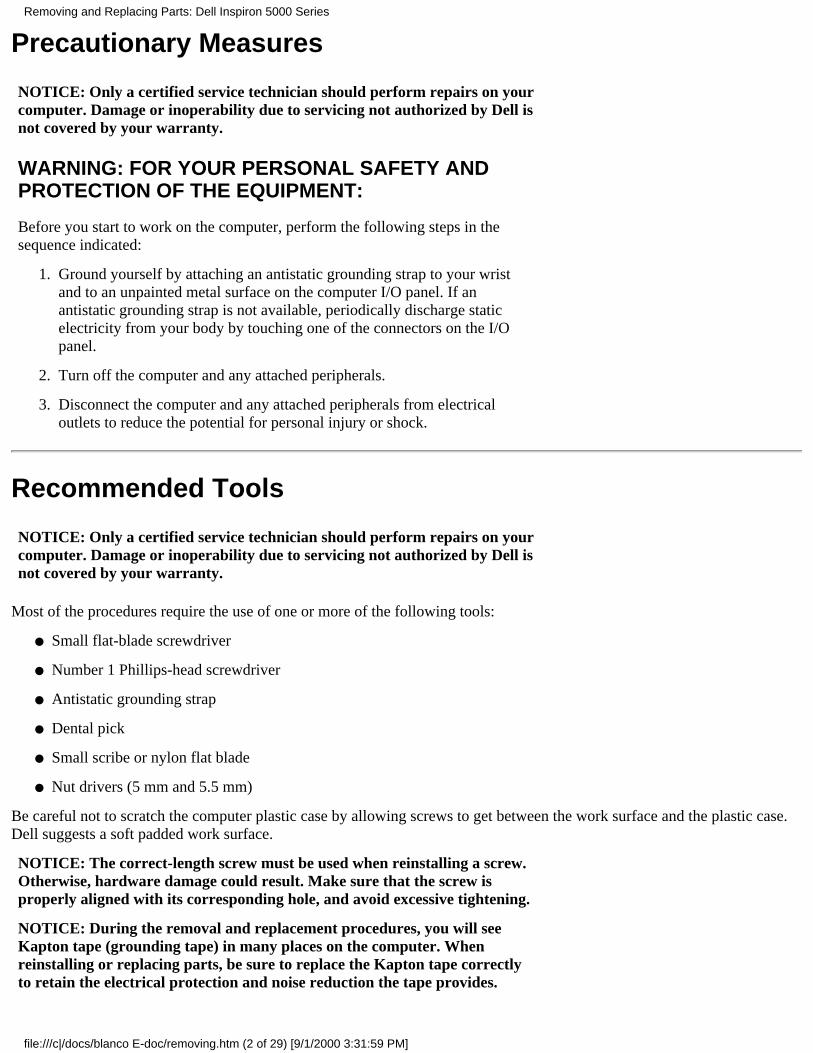
Disconnect the AC adapter cable from the computer.1.
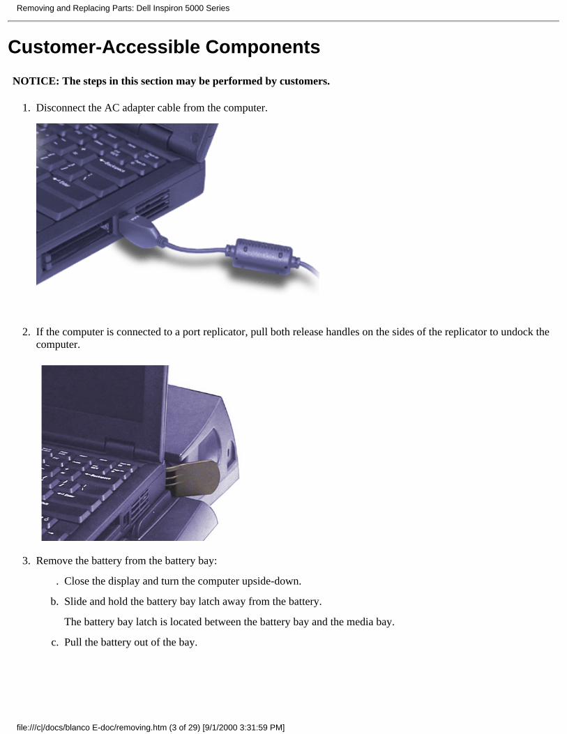
If the computer is connected to a port replicator, pull both release handles on the sides of the replicator to undock thecomputer.
2.
Remove the battery from the battery bay:
Close the display and turn the computer upside-down..
Slide and hold the battery bay latch away from the battery.
The battery bay latch is located between the battery bay and the media bay.
b.
Pull the battery out of the bay.c.
3.
Removing and Replacing Parts: Dell Inspiron 5000 Series
file:///c|/docs/blanco E-doc/removing.htm (3 of 29) [9/1/2000 3:31:59 PM]
NOTICE: Use the PC Card configuration utility on the taskbar to select andstop a card before removing it from the computer. If you do not remove thecard in the configuration utility, you could lose data from open applicationprograms.
Remove any PC Cards:
Press the eject button..
When the button slides out, press it again to release the card.b.
Gently remove the card.c.
Press the eject button once more until it is flush with the computer casing.d.
4.
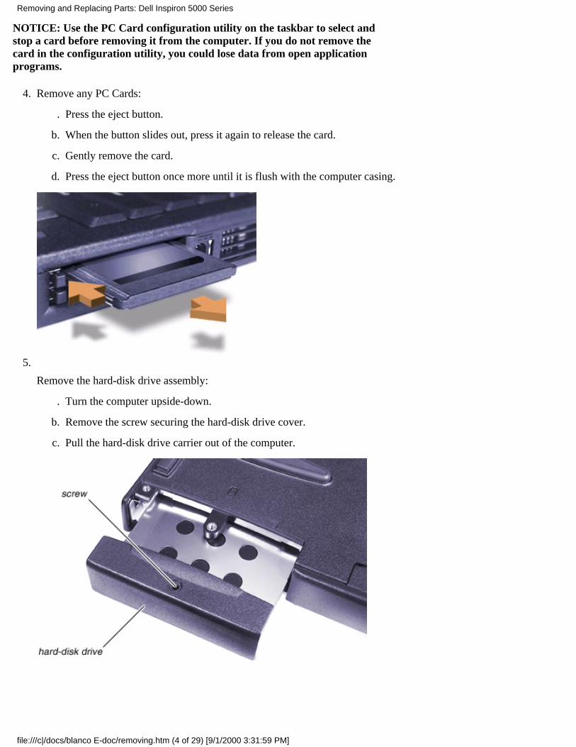
Remove the hard-disk drive assembly:
Turn the computer upside-down..
Remove the screw securing the hard-disk drive cover.b.
Pull the hard-disk drive carrier out of the computer.c.
5.
Removing and Replacing Parts: Dell Inspiron 5000 Series
file:///c|/docs/blanco E-doc/removing.htm (4 of 29) [9/1/2000 3:31:59 PM]
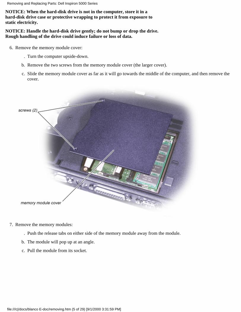
NOTICE: When the hard-disk drive is not in the computer, store it in ahard-disk drive case or protective wrapping to protect it from exposure tostatic electricity.
NOTICE: Handle the hard-disk drive gently; do not bump or drop the drive.Rough handling of the drive could induce failure or loss of data.
Remove the memory module cover:
Turn the computer upside-down..
Remove the two screws from the memory module cover (the larger cover).b.
Slide the memory module cover as far as it will go towards the middle of the computer, and then remove thecover.
c.
6.
Remove the memory modules:
Push the release tabs on either side of the memory module away from the module..
The module will pop up at an angle.b.
Pull the module from its socket.c.
7.
Removing and Replacing Parts: Dell Inspiron 5000 Series
file:///c|/docs/blanco E-doc/removing.htm (5 of 29) [9/1/2000 3:31:59 PM]
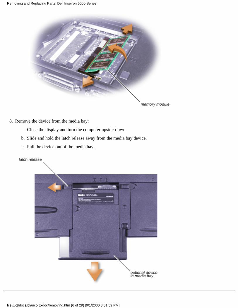
Remove the device from the media bay:
Close the display and turn the computer upside-down..
Slide and hold the latch release away from the media bay device.b.
Pull the device out of the media bay.c.
8.
Removing and Replacing Parts: Dell Inspiron 5000 Series
file:///c|/docs/blanco E-doc/removing.htm (6 of 29) [9/1/2000 3:31:59 PM]
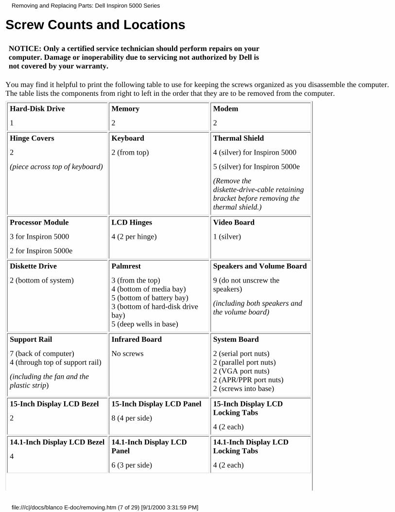
Screw Counts and Locations
NOTICE: Only a certified service technician should perform repairs on yourcomputer. Damage or inoperability due to servicing not authorized by Dell isnot covered by your warranty.
You may find it helpful to print the following table to use for keeping the screws organized as you disassemble the computer.The table lists the components from right to left in the order that they are to be removed from the computer.
Hard-Disk Drive
1
Memory
2
Modem
2
Hinge Covers
2
(piece across top of keyboard)
Keyboard
2 (from top)
Thermal Shield
4 (silver) for Inspiron 5000
5 (silver) for Inspiron 5000e
(Remove thediskette-drive-cable retainingbracket before removing thethermal shield.)
Processor Module
3 for Inspiron 5000
2 for Inspiron 5000e
LCD Hinges
4 (2 per hinge)
Video Board
1 (silver)
Diskette Drive
2 (bottom of system)
Palmrest
3 (from the top)4 (bottom of media bay)5 (bottom of battery bay)3 (bottom of hard-disk drivebay)5 (deep wells in base)
Speakers and Volume Board
9 (do not unscrew thespeakers)
(including both speakers andthe volume board)
Support Rail
7 (back of computer)4 (through top of support rail)
(including the fan and theplastic strip)
Infrared Board
No screws
System Board
2 (serial port nuts)2 (parallel port nuts)2 (VGA port nuts)2 (APR/PPR port nuts)2 (screws into base)
15-Inch Display LCD Bezel
2
15-Inch Display LCD Panel
8 (4 per side)
15-Inch Display LCDLocking Tabs
4 (2 each)
14.1-Inch Display LCD Bezel
4
14.1-Inch Display LCDPanel
6 (3 per side)
14.1-Inch Display LCDLocking Tabs
4 (2 each)
Removing and Replacing Parts: Dell Inspiron 5000 Series
file:///c|/docs/blanco E-doc/removing.htm (7 of 29) [9/1/2000 3:31:59 PM]
LED/Inverter Board
2
ZIF Connectors
NOTICE: ZIF connectors are fragile. To avoid breaking the connectors,touch them carefully. Do not apply too much pressure to the movable part ofthe connector when opening or closing it.
Some of the interface connectors are zero insertion force (ZIF) connectors. These connectors are not removable; they must bereleased to disconnect a cable from them.
To disconnect a cable from a ZIF connector, perform the following steps:
Insert a small flat-blade screwdriver, dental pick, or fingernail under the movable part of the connector.1.
Pull up gently on the movable part of the connector until the cable is released.
Some ZIF connectors may need to be lifted in the center.
2.
Grasp the cable and pull it out of the connector.3.
To reconnect an interface cable to a ZIF connector, perform the following steps:
Open the ZIF connector.1.
Insert the end of the cable into the connector.2.
While holding the cable in place, close the ZIF connector.
To ensure a firm connection, make sure the ZIF connector is completely closed.
3.
Modem Removal
NOTICE: Only a certified service technician should perform repairs on yourcomputer. Damage or inoperability due to servicing not authorized by Dell isnot covered by your warranty.
Ensure that all precautionary measures have been followed and that all customer-accessible parts are removed.
Remove the modem cover.1.
Spread the release tabs on either side of the modem away from the modem.2.
Remove the modem.3.
Remove the modem cable.4.
Removing and Replacing Parts: Dell Inspiron 5000 Series
file:///c|/docs/blanco E-doc/removing.htm (8 of 29) [9/1/2000 3:32:00 PM]

To reinsert the modem when you reassemble the computer, perform the following steps:
Attach the modem cable.1.
Insert the modem into the socket, and rock it up and down until it is completely in place.2.
NOTICE: Fold the modem cable out of the way of the modem door to makesure you do not cut it when you close the modem door.
Hinge Cover Removal
NOTICE: Only a certified service technician should perform repairs on yourcomputer. Damage or inoperability due to servicing not authorized by Dell isnot covered by your warranty.
Remove the hinge cover screws.1.
Removing and Replacing Parts: Dell Inspiron 5000 Series
file:///c|/docs/blanco E-doc/removing.htm (9 of 29) [9/1/2000 3:32:00 PM]
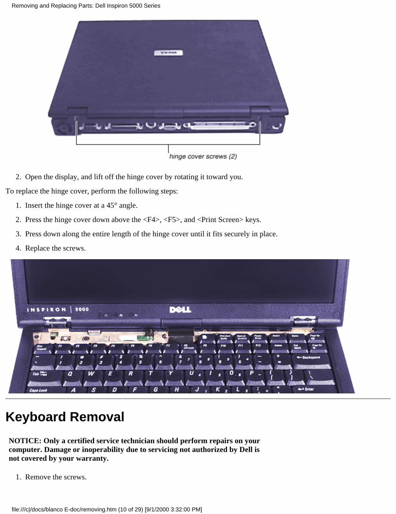
Open the display, and lift off the hinge cover by rotating it toward you. 2.
To replace the hinge cover, perform the following steps:
Insert the hinge cover at a 45° angle.1.
Press the hinge cover down above the <F4>, <F5>, and <Print Screen> keys.2.
Press down along the entire length of the hinge cover until it fits securely in place.3.
Replace the screws.4.
Keyboard Removal
NOTICE: Only a certified service technician should perform repairs on yourcomputer. Damage or inoperability due to servicing not authorized by Dell isnot covered by your warranty.
Remove the screws.1.
Removing and Replacing Parts: Dell Inspiron 5000 Series
file:///c|/docs/blanco E-doc/removing.htm (10 of 29) [9/1/2000 3:32:00 PM]
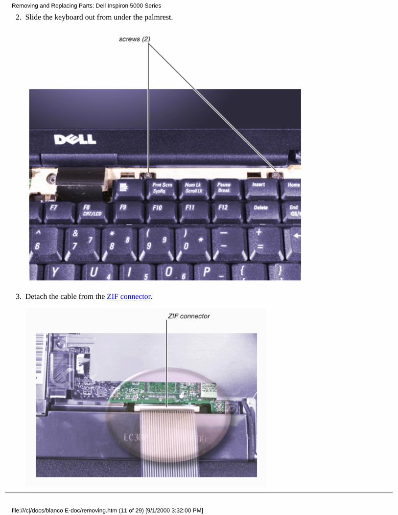
Slide the keyboard out from under the palmrest.2.
Detach the cable from the ZIF connector.3.
Removing and Replacing Parts: Dell Inspiron 5000 Series
file:///c|/docs/blanco E-doc/removing.htm (11 of 29) [9/1/2000 3:32:00 PM]
Thermal Shield Removal
NOTICE: Only a certified service technician should perform repairs on yourcomputer. Damage or inoperability due to servicing not authorized by Dell isnot covered by your warranty.
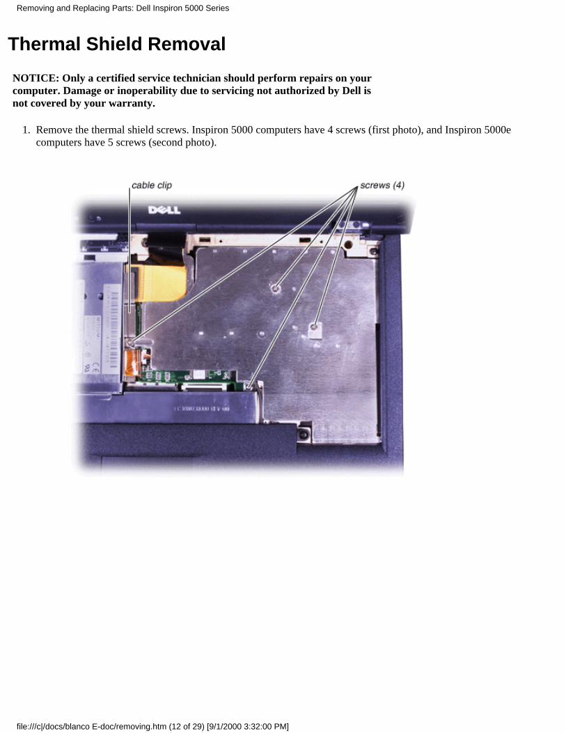
Remove the thermal shield screws. Inspiron 5000 computers have 4 screws (first photo), and Inspiron 5000ecomputers have 5 screws (second photo).
1.
Removing and Replacing Parts: Dell Inspiron 5000 Series
file:///c|/docs/blanco E-doc/removing.htm (12 of 29) [9/1/2000 3:32:00 PM]
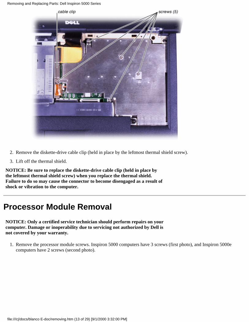
Remove the diskette-drive cable clip (held in place by the leftmost thermal shield screw).2.
Lift off the thermal shield.3.
NOTICE: Be sure to replace the diskette-drive cable clip (held in place bythe leftmost thermal shield screw) when you replace the thermal shield.Failure to do so may cause the connector to become disengaged as a result ofshock or vibration to the computer.
Processor Module Removal
NOTICE: Only a certified service technician should perform repairs on yourcomputer. Damage or inoperability due to servicing not authorized by Dell isnot covered by your warranty.
Remove the processor module screws. Inspiron 5000 computers have 3 screws (first photo), and Inspiron 5000ecomputers have 2 screws (second photo).
1.
Removing and Replacing Parts: Dell Inspiron 5000 Series
file:///c|/docs/blanco E-doc/removing.htm (13 of 29) [9/1/2000 3:32:00 PM]
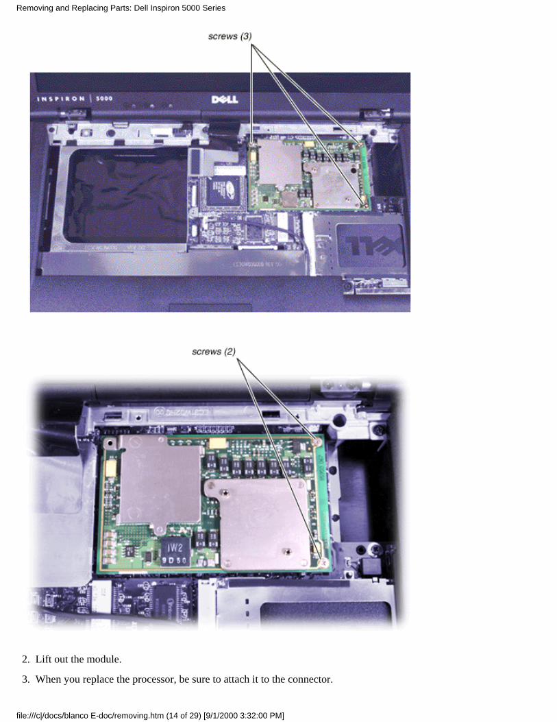
Lift out the module.2.
When you replace the processor, be sure to attach it to the connector.3.
Removing and Replacing Parts: Dell Inspiron 5000 Series
file:///c|/docs/blanco E-doc/removing.htm (14 of 29) [9/1/2000 3:32:00 PM]
When you replace the processor during reassembly, be sure to attach it to the connector.
LCD Removal
NOTICE: Only a certified service technician should perform repairs on yourcomputer. Damage or inoperability due to servicing not authorized by Dell isnot covered by your warranty.
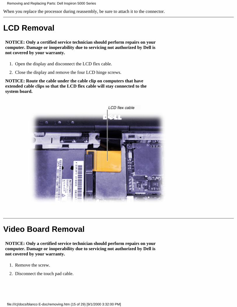
Open the display and disconnect the LCD flex cable.1.
Close the display and remove the four LCD hinge screws.2.
NOTICE: Route the cable under the cable clip on computers that haveextended cable clips so that the LCD flex cable will stay connected to thesystem board.
Video Board Removal
NOTICE: Only a certified service technician should perform repairs on yourcomputer. Damage or inoperability due to servicing not authorized by Dell isnot covered by your warranty.
Remove the screw.1.
Disconnect the touch pad cable.2.
Removing and Replacing Parts: Dell Inspiron 5000 Series
file:///c|/docs/blanco E-doc/removing.htm (15 of 29) [9/1/2000 3:32:00 PM]

Diskette Drive Removal
NOTICE: Only a certified service technician should perform repairs on yourcomputer. Damage or inoperability due to servicing not authorized by Dell isnot covered by your warranty.
Detach the data cable.1.
Removing and Replacing Parts: Dell Inspiron 5000 Series
file:///c|/docs/blanco E-doc/removing.htm (16 of 29) [9/1/2000 3:32:00 PM]
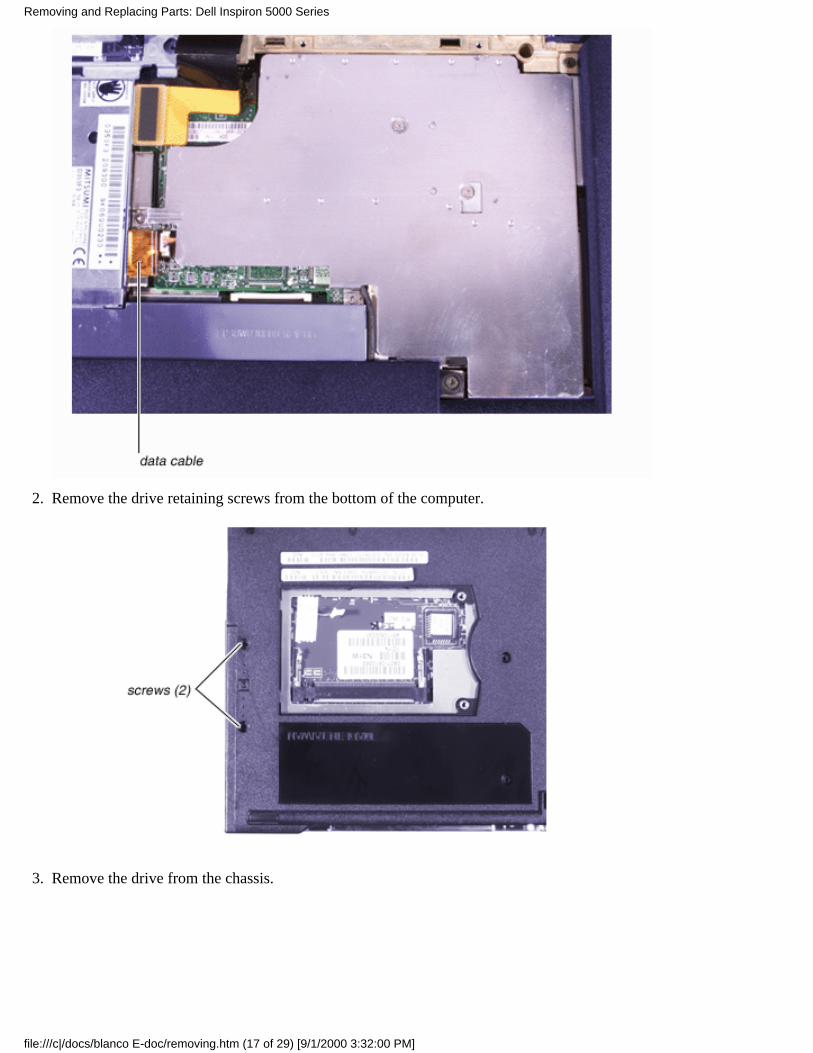
Remove the drive retaining screws from the bottom of the computer.2.
Remove the drive from the chassis.3.
Removing and Replacing Parts: Dell Inspiron 5000 Series
file:///c|/docs/blanco E-doc/removing.htm (17 of 29) [9/1/2000 3:32:00 PM]
Palmrest Removal
NOTICE: Only a certified service technician should perform repairs on yourcomputer. Damage or inoperability due to servicing not authorized by Dell isnot covered by your warranty.
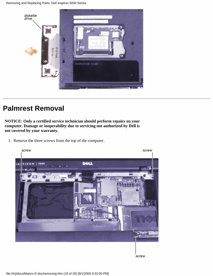
Remove the three screws from the top of the computer.1.
Removing and Replacing Parts: Dell Inspiron 5000 Series
file:///c|/docs/blanco E-doc/removing.htm (18 of 29) [9/1/2000 3:32:00 PM]
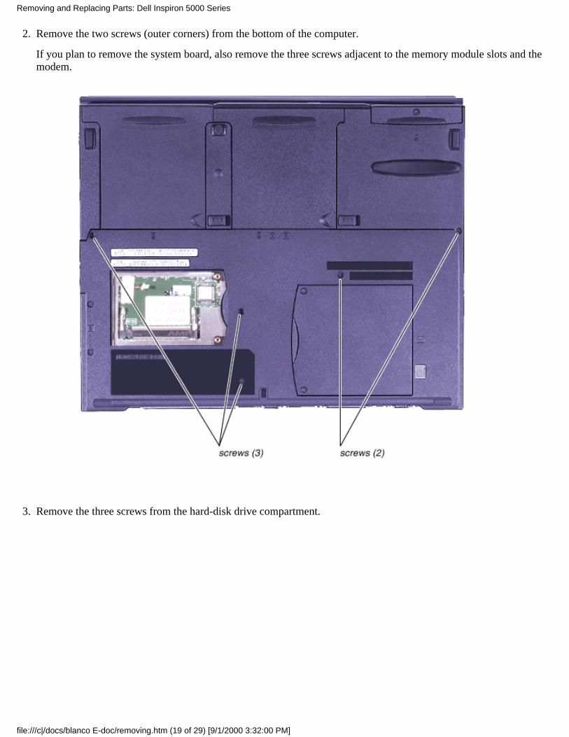
Remove the two screws (outer corners) from the bottom of the computer.
If you plan to remove the system board, also remove the three screws adjacent to the memory module slots and themodem.
2.
Remove the three screws from the hard-disk drive compartment.3.
Removing and Replacing Parts: Dell Inspiron 5000 Series
file:///c|/docs/blanco E-doc/removing.htm (19 of 29) [9/1/2000 3:32:00 PM]
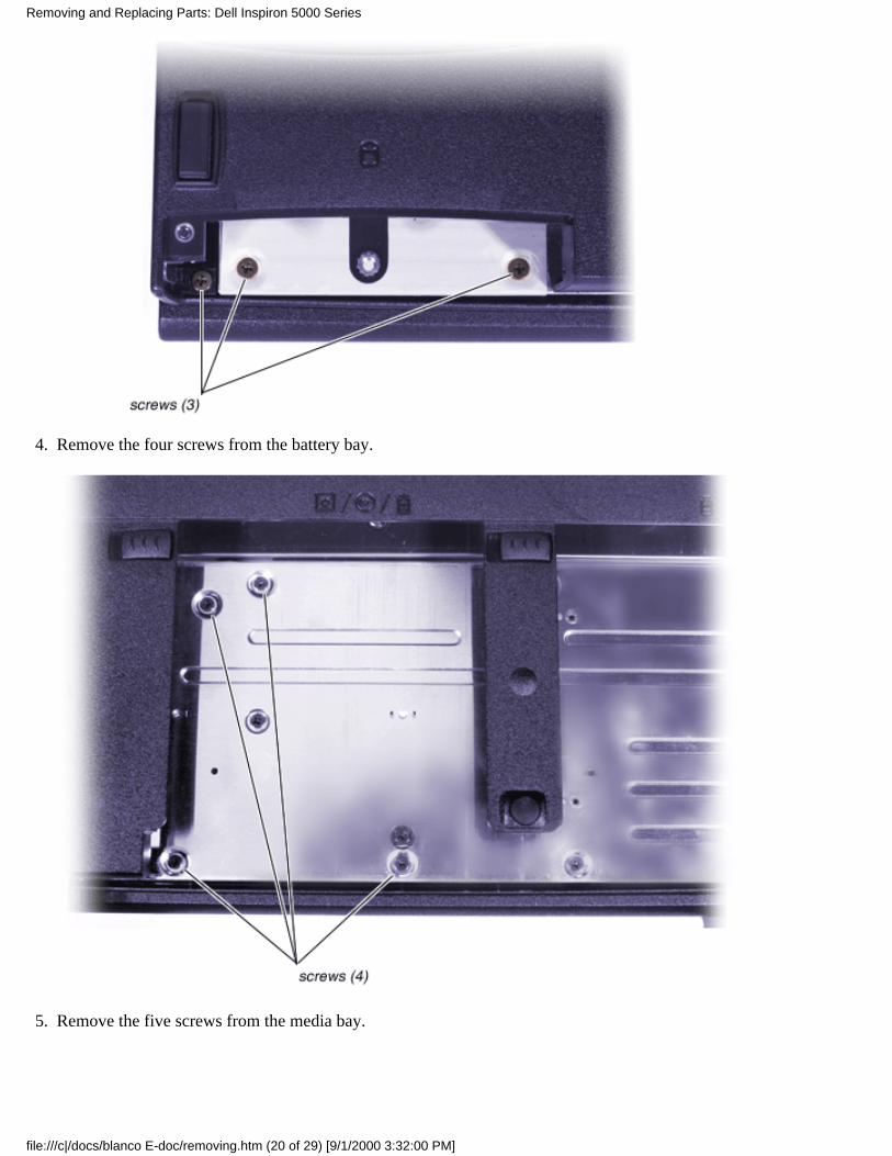
Remove the four screws from the battery bay.4.
Remove the five screws from the media bay.5.
Removing and Replacing Parts: Dell Inspiron 5000 Series
file:///c|/docs/blanco E-doc/removing.htm (20 of 29) [9/1/2000 3:32:00 PM]

Speaker and Volume Board Removal
NOTICE: Only a certified service technician should perform repairs on yourcomputer. Damage or inoperability due to servicing not authorized by Dell isnot covered by your warranty.
Remove the nine screws.1.
Disconnect the speaker cable. Be sure to carefully remove the Kapton tape that holds the speaker cable in position onthe left side.
2.
Disconnect the volume cable.3.
NOTICE: When you replace the speaker and volume board, be sure not tocut the modem cable.
Removing and Replacing Parts: Dell Inspiron 5000 Series
file:///c|/docs/blanco E-doc/removing.htm (21 of 29) [9/1/2000 3:32:00 PM]
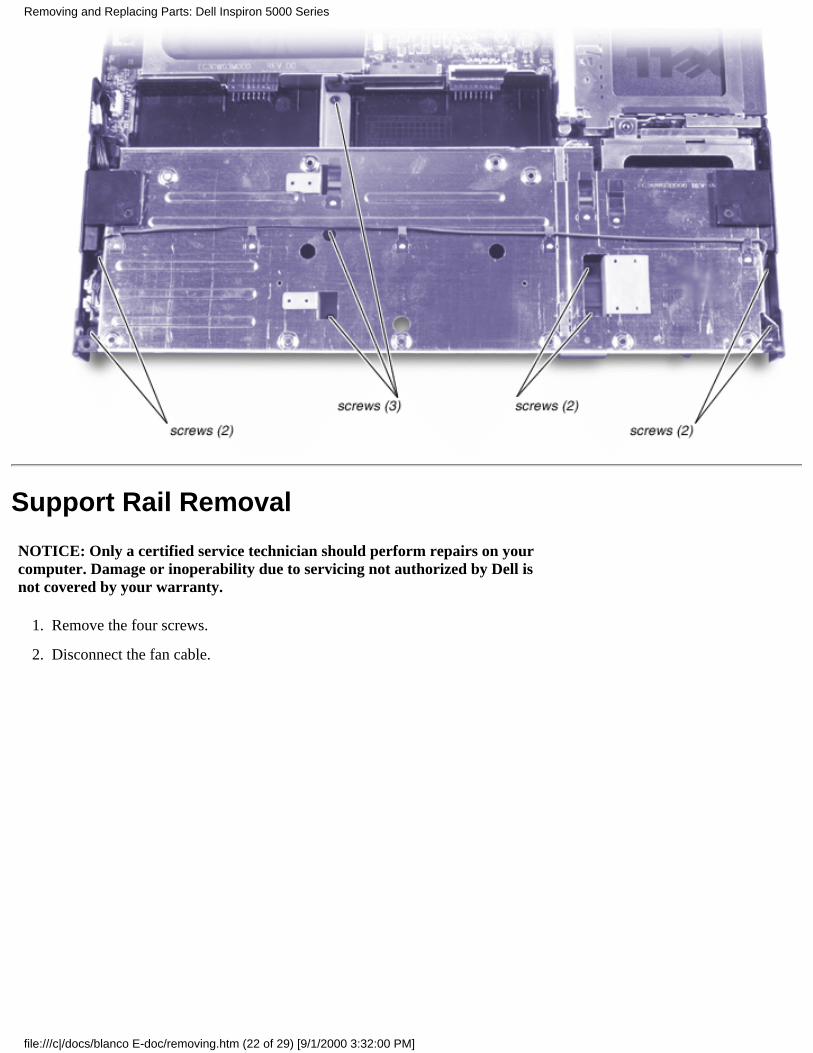
Support Rail Removal
NOTICE: Only a certified service technician should perform repairs on yourcomputer. Damage or inoperability due to servicing not authorized by Dell isnot covered by your warranty.
Remove the four screws.1.
Disconnect the fan cable.2.
Removing and Replacing Parts: Dell Inspiron 5000 Series
file:///c|/docs/blanco E-doc/removing.htm (22 of 29) [9/1/2000 3:32:00 PM]

Remove the seven screws from the back of the computer.3.
Infrared Board Removal
NOTICE: Only a certified service technician should perform repairs on yourcomputer. Damage or inoperability due to servicing not authorized by Dell isnot covered by your warranty.
Disconnect the infrared board from the system board.
Removing and Replacing Parts: Dell Inspiron 5000 Series
file:///c|/docs/blanco E-doc/removing.htm (23 of 29) [9/1/2000 3:32:00 PM]
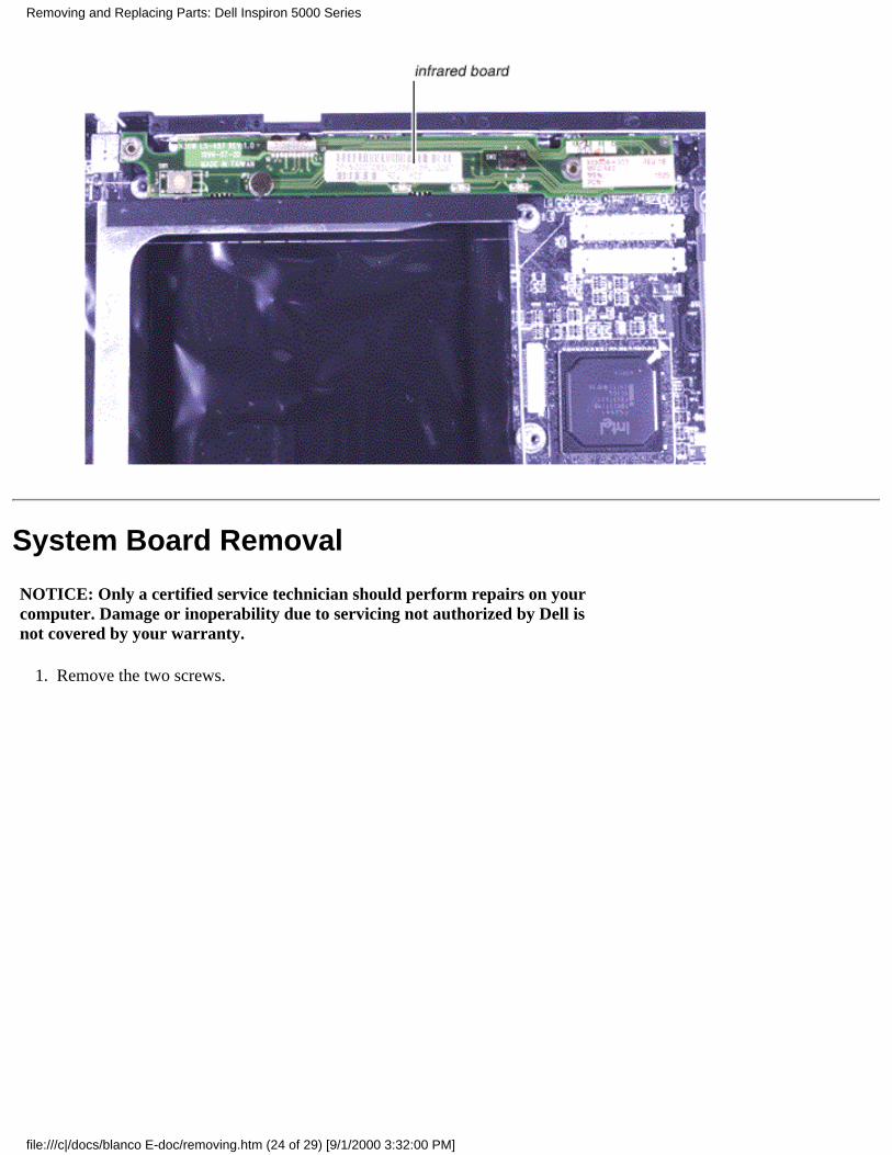
System Board Removal
NOTICE: Only a certified service technician should perform repairs on yourcomputer. Damage or inoperability due to servicing not authorized by Dell isnot covered by your warranty.
Remove the two screws.1.
Removing and Replacing Parts: Dell Inspiron 5000 Series
file:///c|/docs/blanco E-doc/removing.htm (24 of 29) [9/1/2000 3:32:00 PM]
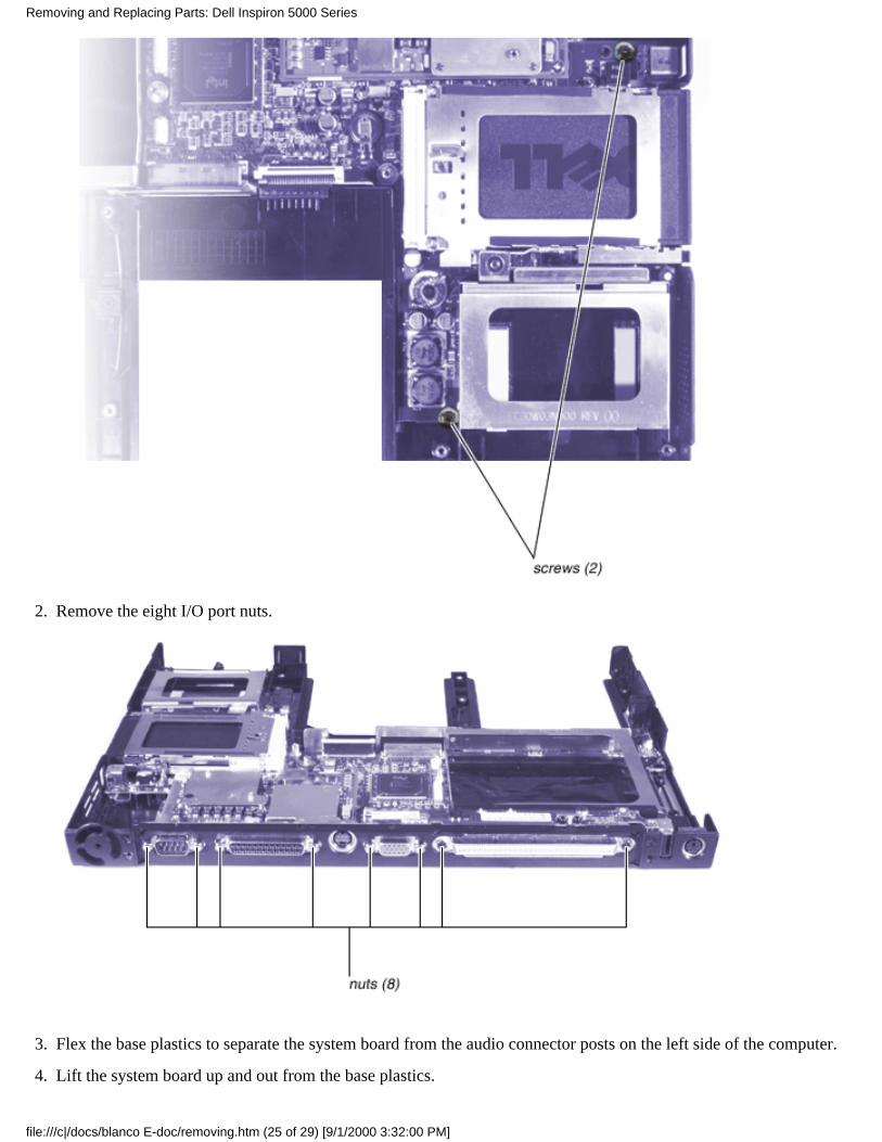
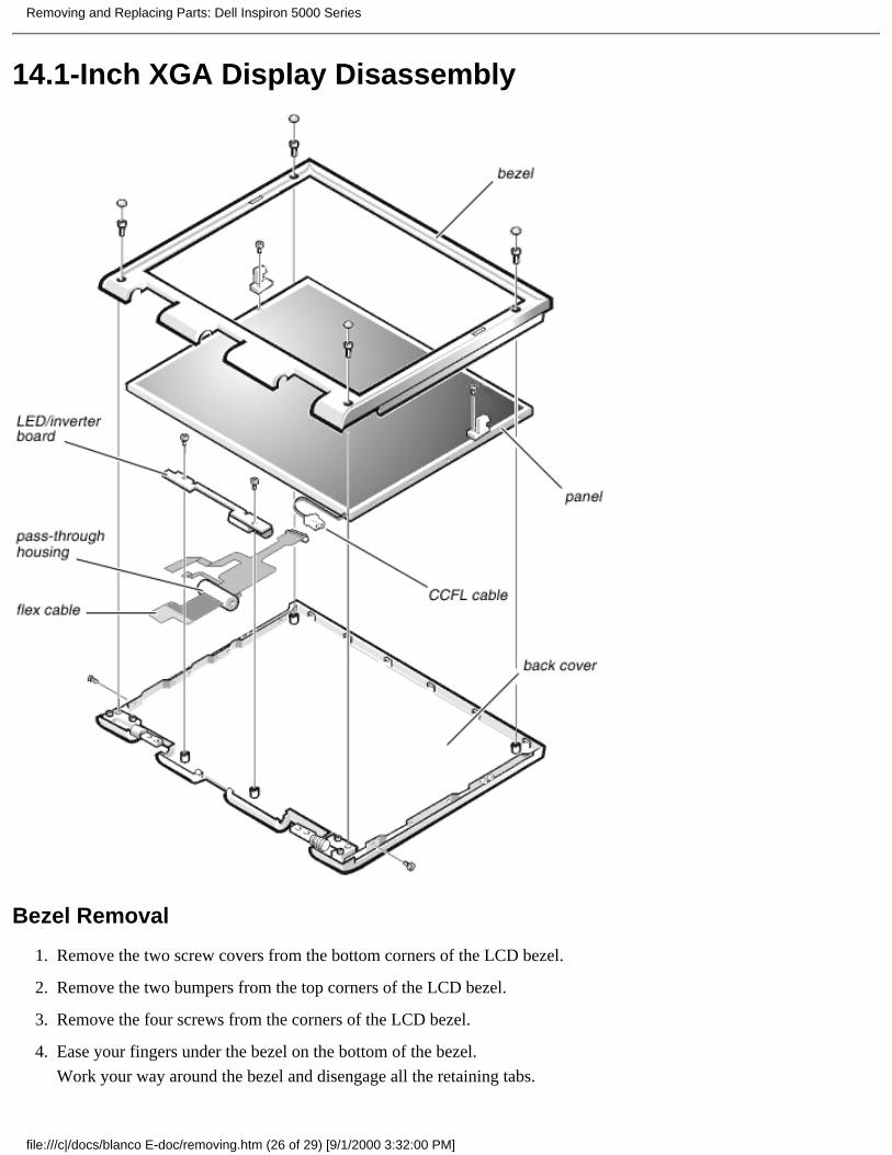
Remove the eight I/O port nuts.2.
Flex the base plastics to separate the system board from the audio connector posts on the left side of the computer.3.
Lift the system board up and out from the base plastics.4.
Removing and Replacing Parts: Dell Inspiron 5000 Series
file:///c|/docs/blanco E-doc/removing.htm (25 of 29) [9/1/2000 3:32:00 PM]
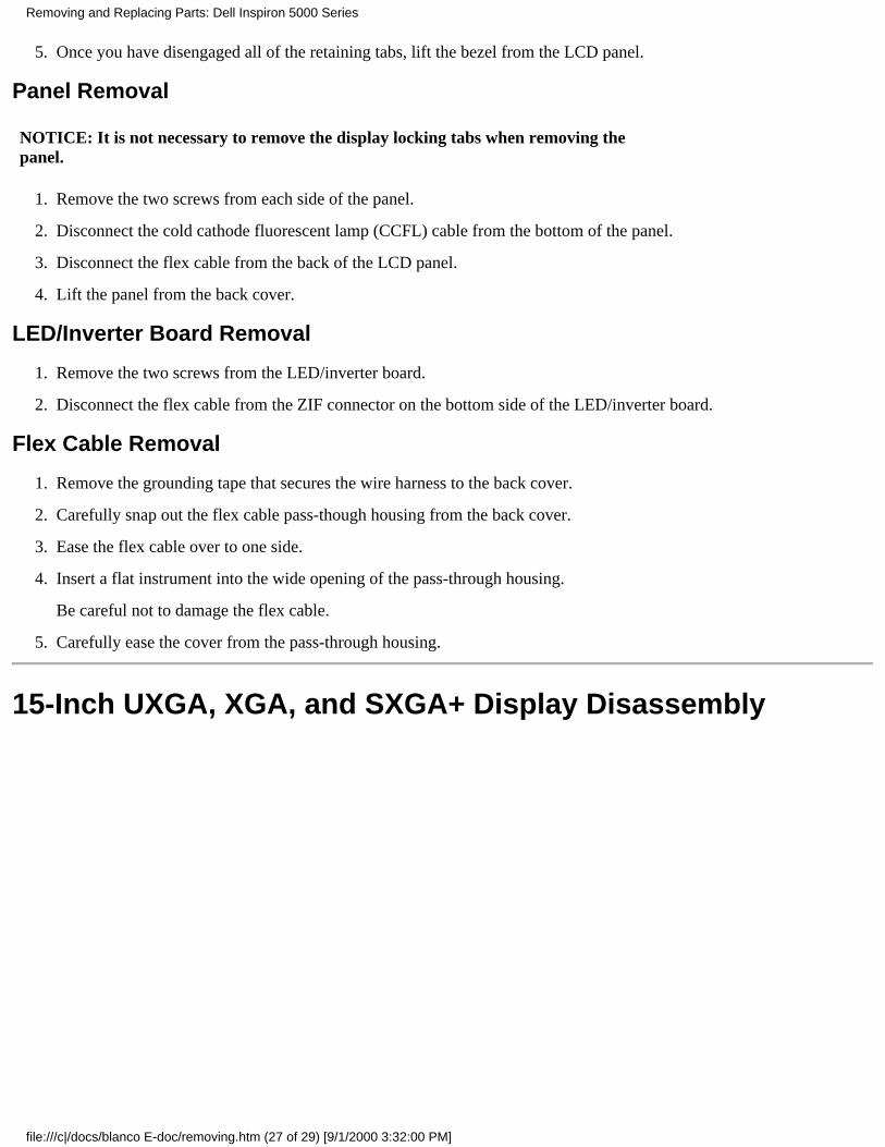
14.1-Inch XGA Display Disassembly
Bezel Removal
Remove the two screw covers from the bottom corners of the LCD bezel.1.
Remove the two bumpers from the top corners of the LCD bezel.2.
Remove the four screws from the corners of the LCD bezel.3.
Ease your fingers under the bezel on the bottom of the bezel.
Work your way around the bezel and disengage all the retaining tabs.
4.
Removing and Replacing Parts: Dell Inspiron 5000 Series
file:///c|/docs/blanco E-doc/removing.htm (26 of 29) [9/1/2000 3:32:00 PM]
Once you have disengaged all of the retaining tabs, lift the bezel from the LCD panel.5.
Panel Removal
NOTICE: It is not necessary to remove the display locking tabs when removing thepanel.
Remove the two screws from each side of the panel.1.
Disconnect the cold cathode fluorescent lamp (CCFL) cable from the bottom of the panel.2.
Disconnect the flex cable from the back of the LCD panel.3.
Lift the panel from the back cover.4.
LED/Inverter Board Removal
Remove the two screws from the LED/inverter board.1.
Disconnect the flex cable from the ZIF connector on the bottom side of the LED/inverter board.2.
Flex Cable Removal
Remove the grounding tape that secures the wire harness to the back cover.1.
Carefully snap out the flex cable pass-though housing from the back cover.2.
Ease the flex cable over to one side.3.
Insert a flat instrument into the wide opening of the pass-through housing.
Be careful not to damage the flex cable.
4.
Carefully ease the cover from the pass-through housing.5.
15-Inch UXGA, XGA, and SXGA+ Display Disassembly
Removing and Replacing Parts: Dell Inspiron 5000 Series
file:///c|/docs/blanco E-doc/removing.htm (27 of 29) [9/1/2000 3:32:00 PM]

Bezel Removal
Remove the two screw covers from the bottom corners of the LCD bezel.1.
Remove the two screws from the bottom corners of the LCD panel.2.
Ease your fingers under the bezel at the top of the panel.
Work your way around the bezel and disengage all the retaining tabs.
3.
Once you have disengaged all of the retaining tabs, lift the bezel from the LCD panel.4.
Panel Removal
Remove the two latch assembly screws from each of the two display locking tabs.1.
Remove the four screws from each side of the LCD panel.2.
Removing and Replacing Parts: Dell Inspiron 5000 Series
file:///c|/docs/blanco E-doc/removing.htm (28 of 29) [9/1/2000 3:32:00 PM]
Disconnect the CCFL cable from the bottom of the panel.3.
Disconnect the flex cable from the LCD panel.4.
Lift the LCD panel from the back cover.5.
LED/Inverter Board Removal
Remove the two screws from the LED/inverter board.1.
Disconnect the flex cable from the ZIF connector on the bottom side of the LED/inverter board.2.
Flex Cable Removal
Remove the grounding tape that secures the wire harness to the back cover.1.
Carefully snap out the flex cable pass-though housing from the back cover.2.
Ease the flex cable over to one side.3.
Insert a flat instrument into the wide opening of the pass-through housing.
Be careful not to damage the flex cable.
4.
Carefully ease the cover from the pass-through housing.5.
Removing and Replacing Parts: Dell Inspiron 5000 Series
file:///c|/docs/blanco E-doc/removing.htm (29 of 29) [9/1/2000 3:32:00 PM]