remote tester for point smoke detectors ... - scorpion tester · scorpion is a unique, functional...
TRANSCRIPT

www. .comscorpion-tester
scorpion®
Remote Tester for Point Smoke Detectors& Aspirating Smoke Detection (ASD) Systems
User Manual
*Note: The ASD pipe and brackets shown in the illustration above andwithin this manual are not part of the Scorpion ASD product line.

User ManualThis manual provides information for the correct use of scorpion®
Remote Detector Test System
System Components:
i
scorpion®
For any additional information or technical support, please visitthe Scorpion web site at: www.scorpion-tester.com
Scorpion Point Head Unit Kit
SCORP 1001(including Door Detectors)
Scorpion Battery Cable
SCORP 60(for connecting Solo 760
Battery Baton to ScorpionControl Panel)
Scorpion ASD Head Unit Kit
SCORP 2001
Scorpion Power Pack
SCORP 50
Solo Battery Baton
(optional)SOLO 760
www. .comscorpion-tester
Scorpion Access Point
SCORP 25(for single heads)
Solo Universal Fast
Battery Charger
SOLO 726
Scorpion Control Cable
SPARE 1054(for connecting Portable
Controller, SCORP 7000 toAccess Point, SCORP 25)
Scorpion Portable
Controller
SCORP 7000 (for single heads) -Includes Control Cable (SCORP 1054)
and Battery Cable (SCORP 60)
Scorpion Wall Mounted
Controller
SCORP 8000(for multiple heads)
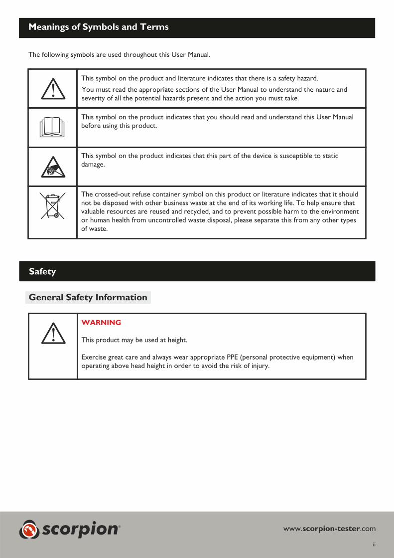
This symbol on the product indicates that there is a safety hazard.and literature
This symbol on the product indicates that you should read and understand this User Manualbefore using this product.
This symbol on the product indicates that this part of the device is susceptible to taticsdamage.
The crossed-out refuse container symbol on this product or literature indicates that it shouldnot be disposed with other business waste at the end of its working life. To help ensure thatvaluable resources are reused and recycled, and to prevent possible harm to the environmentor human health from uncontrolled waste disposal, please separate this from any other typesof waste.
You must read th User Manual to understand the nature ande appropriate sections of theseverity of all the hazards present and the action you must take.potential
Meanings of ymbols and ermsS T
The following symbols are used throughout th anual.is User M
ii
Safety
WARNING
This product be used at heightmay .
Exercise great care and always wear appropriate protective equipment) whenPPE (personalthe risk ofoperating above head height in order to avoid injury.
General Safety Information
www. .comscorpion-testerscorpion®
Important nformationI
���Read this User Manual completely before using your Scorpion System.
���� Save ht is User Manual - Save all safety and operational instructions for future reference.
���� Take note of the Cautions and Warnings - Read carefully and follow all warning labels on the product and thoseis User Manualdescribed in th .
���� Installation of the Scorpion system must not obstruct or impair the operation of the fire system.
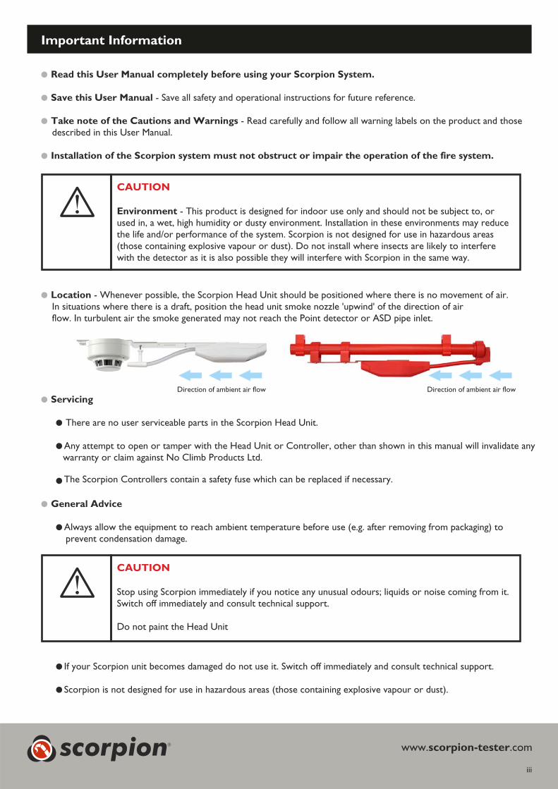
���� Location - Whenever possible, the Scorpion Head Unit should be positioned where there is no movement of air.In situations where there is a draft, position the head unit smoke nozzle 'upwind' of the direction of airflow. In turbulent air the smoke generated may not reach the Point detector or ASD pipe inlet.
���Servicing
�������� There are no user serviceable parts in the Scorpion Head Unit.�
��������Any attempt to open or tamper with the Head Unit or Controller, other than shown in this manual will invalidate anywarranty or claim against No Climb Products Ltd.
��������The Scorpion Controllers contain a safety fuse which can be replaced if necessary.
���� General Advice
��������Always allow the equipment to reach ambient temperature before use (e.g. after removing from packaging) toprevent condensation damage.
��������If your Scorpion unit becomes damaged do not use it. Switch off immediately and consult technical support.
��������Scorpion is not designed for use in hazardous areas (those containing explosive vapour or dust).
iii
scorpion® www. .comscorpion-tester
CAUTION
Environment - T or indoor use only and should not be subject to, orhis product is designed fused in, a wet, high humidity or dusty environment. Installation in these environments may reducethe life and/or performance of the system. Scorpion is not designed for use in hazardous areas(those containing explosive vapour or dust). Do not install where insects are likely to interferewith the detector as it is also possible they will interfere with Scorpion in the same way.
Direction of ambient air flow Direction of ambient air flow
CAUTION
Stop using Scorpion immediately if you notice any unusual odours; liquids or noise coming from it.Switch off immediately and consult technical support.
Do not paint the Head Unit
��������Use only approved accessories that are recommended by the manufacturer.
��������The Scorpion Battery Pack or Solo Battery Baton should be removed when Scorpion is not in use. This willprevent gradual discharge of the battery and prevent possible accidental or malicious operation of the head unit.
��������Always use a fully charged battery when commissioning the system.
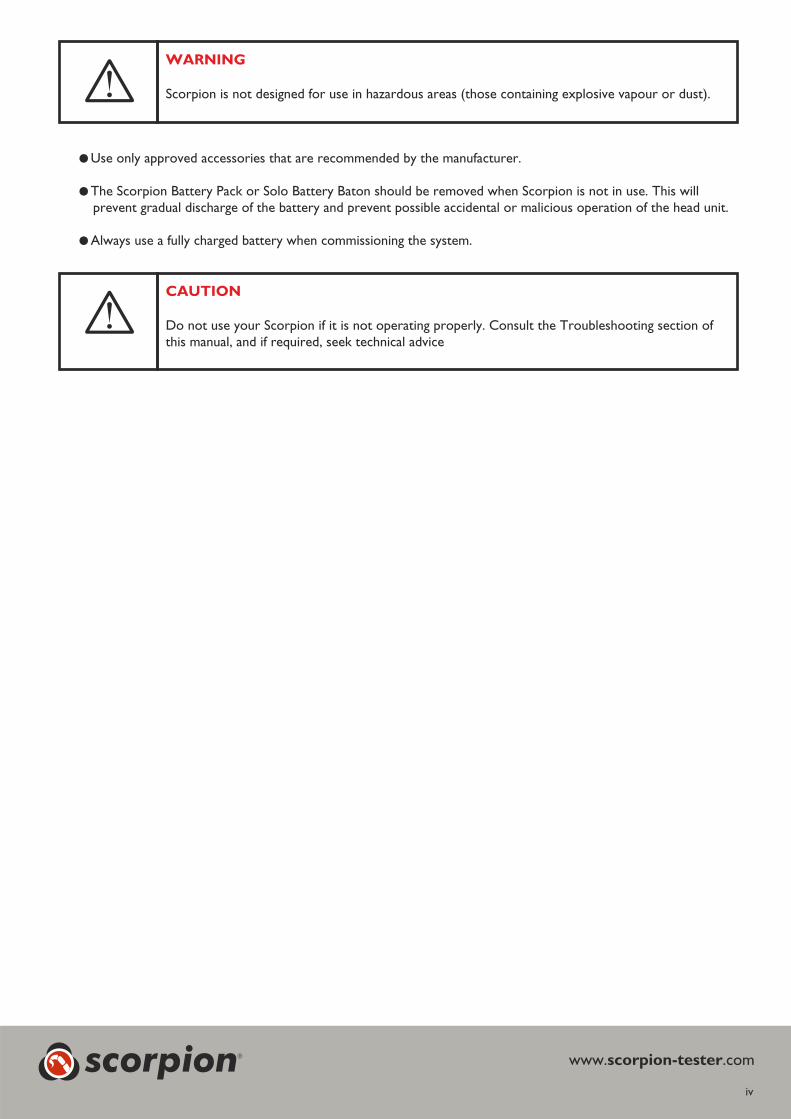
WARNING
Scorpion is not designed for use in hazardous areas (those containing explosive vapour or dust).
CAUTION
Do not use your Scorpion if it is not operating properly. Consult the Troubleshooting section ofthis manual, and if required, seek technical advice
iv
www. .comscorpion-testerscorpion®
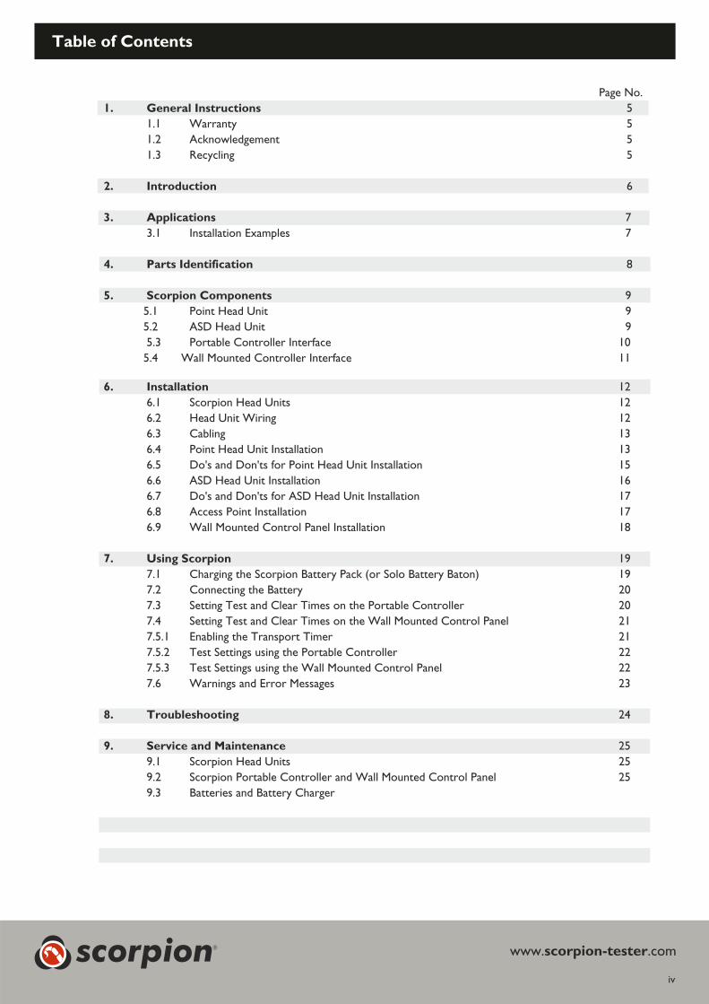
Table of Contents
iv
Page No.
1. General Instructions 5
1.1 Warranty 5
1.2 Acknowledgement 5
1.3 Recycling 5
2. Introduction 6
3. Applications 7
3.1 Installation Examples 7
4. Parts Identification 8
5. Scorpion Components 9
5.1 Point Head Unit 9
5.2 ASD Head Unit 9
5.3 Portable Controller Interface 10
5.4 Wall Mounted Controller Interface 11
6. Installation 12
6.1 Scorpion Head Units 12
6.2 Head Unit Wiring 12
6.3 Cabling 13
6.4 Point Head Unit Installation 13
6.5 Do's and Don'ts for Point Head Unit Installation 15
6.6 ASD Head Unit Installation 16
6.7 Do's and Don'ts for ASD Head Unit Installation 17
6.8 Access Point Installation 17
6.9 Wall Mounted Control Panel Installation 18
7. Using Scorpion 19
7.1 Charging the Scorpion Battery Pack (or Solo Battery Baton) 19
7.2 Connecting the Battery 20
7.3 Setting Test and Clear Times on the Portable Controller 20
7.4 Setting Test and Clear Times on the Wall Mounted Control Panel 21
7.5.1 Enabling the Transport Timer 21
7.5.2 Test Settings using the Portable Controller 22
7.5.3 Test Settings using the Wall Mounted Control Panel 22
7.6 Warnings and Error Messages 23
8. Troubleshooting 24
9. Service and Maintenance 25
9.1 Scorpion Head Units 25
9.2 Scorpion Portable Controller and Wall Mounted Control Panel 25
9.3 Batteries and Battery Charger
www. .comscorpion-testerscorpion®

1. General Instructions
1.1 Warranty
In addition to any other express warranty given in writing by the Company in relation to the Goods the Company,warrants that the Goods supplied under the terms and conditions will be in accordance with the specification(if any) contained in the Order, and will be free from defects in workmanship and material for a period ofPurchase18 months from the date of delivery to the Buyer or for a period 12 months after the date of sale by the Buyerofto customer whichever period is the shorter.the final Warranty is limited to the replacement of Scorpion systemonly.
Keep a record of the serial numbers of the components, particularly the Head Units, as these will be needed toverify the warranty status. Make a note of these before installation as they will be inaccessibly once the Head Unitis fitted to the mounting bracket. The serial number is printed on the Head Unit label and on the packaging label.Make a note of the model, serial number, and date of purchase.
1.2 Acknowledgement
Scorpion® registered mark of . All other brand names mentioned are trademarksis a No Climb Products Ltd
or registered marks of their respective holders, and are hereby acknowledged. ©20 No Climb Products Ltd. All12
Rights Reserved.
1.3 Recycling
The packaging eas y separa intocan be il tedthe following materials:
���Cardboard ( box)outer���Cardboard inner s, boxes( buffer )���Polyethylene (bags)���P (lastic / metal any items or accessories
that are not required for a specificinstallation)
Please dispose in line with localenvironmental requirements.
CE Declaration
This product and its associated components are designed and manufactured to be fully compliant with therequirements of the following EU Directives for CE marking:
�� EMC Directive 2004/108/EC of the European Parliament and of the Council of 15 December 2004 on theapproximation of the laws of the Member States relating to electromagnetic compatibility.
�� Low Voltage Directive 2006/95/EC of the European Parliament and of the Council of 12 December 2006 on theharmonisation of the laws of Member States relating to electrical equipment designed for use within certainvoltage limits.
�� RoHS Directive 2011/65/EU of the European Parliament and of the Council of 8 June 2011 on the restriction ofthe use of certain hazardous substances in electrical and electronic equipment.
WEEE (Waste Electrical & Electronic Equipment) Regulations 2006
Scorpion components are suitably marked to be recycled in accordance with your local environmentalrequirements. When supplied as B2B EEE, the provider invokes regulation 9.2 and passes all WEE obligations tothe end user.
page 5
www. .comscorpion-testerscorpion®

2. Introduction
page 6
Thank you for purchasing the Scorpion Remote Test System.
Scorpion is a unique, functional remote smoke detector test system that assists compliance with codesand standards for testing fire detection systems, while delivering radical time, cost and disruption savingsand considerable enhancements to safety.
Scorpion can be used on Aspirating Systems (ASD) as well as Point smoke detectors, on new or retrofitinstallations. Point and ASD heads can be connected to the same Control Panel and can be located up to100m away from the panel, depending on the cable type used.
Each Head Unit will provide in excess of 240 tests of 15 seconds each.
Scorpion for Point Smoke Detectors
The is a smoke generator which is permanently installed adjacent to a standardScorpion Point Head
point smoke detector but which uses its own cabling and remains discrete from the fire detection system.
A Clearing function is available that blows air through the detector which helps remove smoke from thedetector to enable it to reset more quickly, and reduces repeat alarms.
Scorpion for ASD systems
Traditional post commissioning ASD testing is generally performed by trying to introduce a test smoke(often of inappropriate suitability or even questionable quality) into individual sampling points. Not onlycan this be highly impractical but it can also contaminate an ASD system. Scorpion offers an approved,benign and effectively non contaminating test particulate delivered in a controlled and repeatable manner.
With a permanently positioned at the end of a pipe run, a repeatable andScorpion ASD Head Unit
consistent test is achieved throughout the system's lifetime. By recording the moment of Scorpionactivation and the moment of alarm signal, the transport time is measured. Comparing this against theretained commissioning data, previous tests and the acceptable tolerances enables judgments to be maderegarding the integrity of the aspirating system.
If you require additional information or assistance in the use of , please visit the support area ofScorpion
our web site, or contact our technical support department as detailed on the Support page of this UserManual.
www. .comscorpion-testerscorpion®
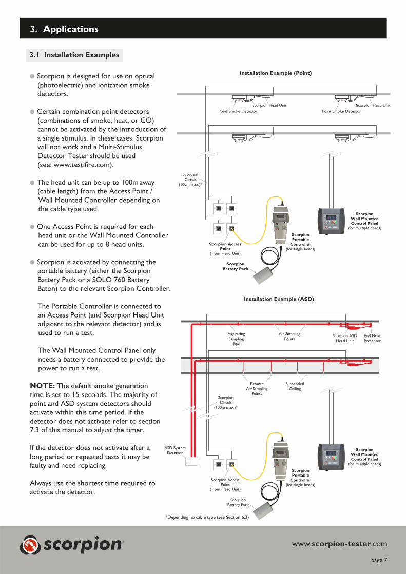
���Scorpion is designed for use on optical(photoelectric) and ionization smokedetectors.
���Certain combination point detectors(combinations of smoke, heat, or CO)cannot be activated by the introduction ofa single stimulus. In these cases, Scorpionwill not work and a Multi-StimulusDetector Tester should be used(see: www.testifire.com).
���The head unit can be up to 100maway(cable length) from the Access Point /Wall Mounted Controller depending onthe cable type used.
���One Access Point is required for eachhead unit or the Wall Mounted Controllercan be used for up to 8 head units.
���Scorpion is activated by connecting theportable battery (either the ScorpionBattery Pack or a SOLO 760 BatteryBaton) to the relevant Scorpion Controller.
The Portable Controller is connected toan Access Point (and Scorpion Head Unitadjacent to the relevant detector) and isused to run a test.
The Wall Mounted Control Panel onlyneeds a battery connected to provide thepower to run a test.
NOTE: The default smoke generationtime is set to 15 seconds. The majority ofpoint and ASD system detectors shouldactivate within this time period. If thedetector does not activate refer to section7.3 of this manual to adjust the timer.
If the detector does not activate after along period or repeated tests it may befaulty and need replacing.
Always use the shortest time required toactivate the detector.
ScorpionCircuit
(100m max.)*
Point Smoke Detector
Scorpion Head Unit
Point Smoke Detector
Scorpion Head Unit
page 7
3. Applications
3 Installation Examples.1
Installation Example (Point)
Installation Example (ASD)
ScorpionCircuit
(100m max.)*
AspiratingSampling
Pipe
Air SamplingPoints
RemoteAir Sampling
Points
SuspendedCeiling
Scorpion ASDHead Unit
ASD SystemDetector
End HolePresenter
www. .comscorpion-tester
Scorpion AccessPoint
(1 per Head Unit)
ScorpionPortable
Controller(for single heads)
Scorpion
Battery Pack
Scorpion AccessPoint
(1 per Head Unit)
ScorpionBattery Pack
ScorpionWall MountedControl Panel
(for multiple heads)
ScorpionPortable
Controller(for single heads)
ScorpionWall MountedControl Panel
(for multiple heads)
scorpion®
*Depending no cable type (see Section 6.3)

4. Parts Identification
page 8
www. .comscorpion-tester
For any additional information or technical support, please visitthe Scorpion web site at: www.scorpion-tester.com
Scorpion Battery Cable
SCORP 60(for connecting Solo 760
Battery Baton to ScorpionControl Panel)
Solo Battery Baton
(optional)SOLO 760
Solo Universal Fast
Battery Charger
SOLO 726
Scorpion Control Cable
SPARE 1054(for connecting Portable
Controller, SCORP 7000 toAccess Point, SCORP 25)
Scorpion Point Head Unit Kit
SCORP 1001(including Door Detectors)
Scorpion ASD Head Unit Kit
SCORP 2001
Scorpion Power Pack
SCORP 50Scorpion Access Point
SCORP 25(for single heads)Scorpion Wall Mounted
Control Panel
SCORP 8000(for multiple heads)
scorpion®
Scorpion Portable
Controller
SCORP 7000 (for single heads) -Includes Control Cable (SCORP 1054)
and Battery Cable (SCORP 60)
page 9
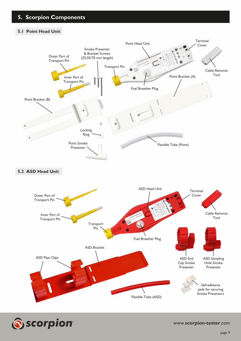
5 1 Point Head Unit.
5 2 ASD Head Unit.
5. Scorpion Components
www. .comscorpion-tester
Point Bracket (B)
Point Bracket (A)
Point Head Unit
Fuel Breather Plug
TerminalCover
Transport Pin
Outer Part ofTransport Pin
Inner Part ofTransport Pin
Flexible Tube (Point)Point SmokePresenter
LockingRing
ASD EndCap SmokePresenter
ASD SamplingHole SmokePresenter
Flexible Tube (ASD)
ASD Head Unit
Fuel Breather Plug
Outer Part ofTransport Pin
Inner Part ofTransport Pin
TransportPin
TerminalCover
Cable RemovalTool
Cable RemovalTool
ASD Pipe Clips
ASD Bracket
Self-adhesivepads for securingSmoke Presenters
Smoke Presenter& Bracket Screws
(25/35/70 mm length)
scorpion®
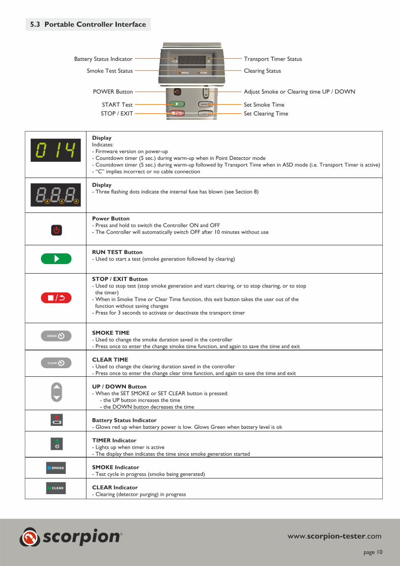
5 3 Portable Controller Interface.
Display
Indicates:- Firmware version on power-up- Countdown timer (5 sec.) during warm-up when in Point Detector mode- Countdown timer (5 sec.) during warm-up followed by Transport Time when in ASD mode (i.e. Transport Timer is active)- “C” implies incorrect or no cable connection
Display
- Three flashing dots indicate the internal fuse has blown (see Section 8)
Power Button
- Press and hold to switch the Controller ON and OFF- The Controller will automatically switch OFF after 10 minutes without use
RUN TEST Button
- Used to start a test (smoke generation followed by clearing)
STOP / EXIT Button
- Used to stop test stop and start clearing, or to stop clearing, or to stop( smoke generationthe timer)
- When in Smoke Time or Clear Time function, this exit button takes the user out of thefunction without saving changes
- Press for 3 seconds to activate or deactivate the transport timer
SMOKE TIME
- Used to change the smoke duration saved in the controller- Press once to enter the change smoke time function, and again to save the time and exit
CLEAR TIME
- Used to change the clearing duration saved in the controller- Press once to enter the change clear time function, and again to save the time and exit
UP / DOWN Button
- When the SET SMOKE or SET CLEAR button is pressed:- the UP button increases the time- the DOWN button decreases the time
Battery Status Indicator
- Glows red up when battery power is low. Glows Green when battery level is ok
TIMER Indicator
- Lights up when timer is active- The display then indicates the time since smoke generation started
SMOKE Indicator
- Test cycle in progress (smoke being generated)
CLEAR Indicator
- Clearing (detector purging) in progress
SMOKE
CLEAR
SMOKE
CLEAR
page 10
www. .comscorpion-testerscorpion®
Transport Timer Status
Clearing Status
Adjust Smoke or Clearing time UP / DOWN
Set Smoke Time
Set Clearing Time
Battery Status Indicator
Smoke Test Status
POWER Button
START Test
STOP / EXIT

Display
Indicates:- Head Unit number (1 - 8)- Timer (counting up in seconds when the ‘time indicator’ LED is on)
Display
Three flashing points indicate a fault has caused the fuse to blow (see Section 9)
UP Button
- Used to select Scorpion Head Unit or adjust timer- When or C button is pressed, th button increases the timeTEST LEAR recessed e UP
DOWN Button
- Used to select Scorpion Head Unit or adjust timer- When or C button is pressed, th decreases the timeTEST LEAR recessed e DOWN button
RUN Button
- Used to start test (smoke generation and/or clearing)
STOP Button
- Used to stop smoke generation and start clearing, or to stop clearing, or to stop timertest ( )- Press for 3 seconds to activate or deactivate timer
Timer Indicator
- Lights up when timer is active- The display then the time since smoke generation startedindicates and/or clearing cycle
T IndicatorEST
- Test in progress moke generatedcycle (s and /or clearing functions)- Button: Press and hold to change smoke durationRecessed with small pointed tool
C IndicatorLEAR
- Clearing (detector purging) in progress.- Button: Press and hold to change clearing timeRecessed with small pointed tool
Battery Status Indicator
- Glows red up when battery power is low. Glows Green when battery level is ok
page 11
TEST
CLEAR
TEST CLEAR
R E M O T E D E T E C T O R
scorpionT E S T T E C H N O L O G Y
®
0 0 0 Time IndicatorBattery Status Indicator
RUN Button
STOP Button
Clearing Indicator
UP Button
DOWN Button
Smoke Test Indicator
Display
Clearing Time Button(recessed)
Smoke Time Button(recessed)
5 4 Wall Mounted Control Panel Interface.
www. .comscorpion-testerscorpion®
page 12
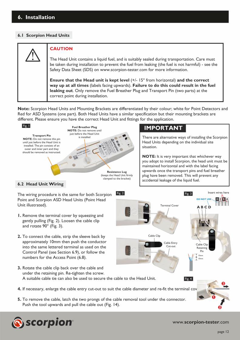
Fig. 1
6. Installation
www. .comscorpion-tester
6.1 Scorpion sHead Unit
Note: Scorpion Head Units and Mounting Brackets are differentiated by their colour; white for Point Detectors andRed for ASD Systems (one part). Both Head Units have a similar specification but their mounting brackets aredifferent. Please ensure you have the correct Head Unit and fittings for the application.
Transport Pin
Do not remove this pinNOTE:
until just before the Head Unit isinstalled. The pin consists of anouter and inner part and they
should be removed as instructed.
Fuel Breather Plug
Do not remove untilNOTE:
just before the Head Unitis installed
Resistance Lug
(keeps the Head Unit firmlyclamped to the bracket)
IMPORTANT
There are alternative ways of installing the ScorpionHead Units depending on the individual sitesituation.
NOTE: It is very important that whichever wayyou adopt to install Scorpion, the head unit must bemaintained horizontal and with the label facingupwards once the transport pins and fuel breatherplug have been removed. This will prevent anyaccidental leakage of the liquid fuel.
6.2 WHead Unit iring
The wiring procedure is the same for both ScorpionPoint and Scorpion ASD Head Units (Point HeadUnit illustrated).
1. Remove the terminal cover by squeezing andgently pulling (Fig. 2). Loosen the cable clipand rotate 90° (Fig. 3).
2. To connect the cable, strip the sleeve back by10approximately mm then push the conductor
into the same lettered terminal as used on the(see Section 6.9), or follow theControl Panel
numbers for the Access Point (6.8).
3. Rotate the cable clip back over the cable andunder the retaining pin. Re-tighten the screw.A suitable cable tie can also be used to secure the cable to the Head Unit.
4. If necessary, enlarge the cable entry cut-out to suit the cable diameter and re-fit the terminal cover.
5. To remove the cable, latch the two prongs of the cable removal tool under the connector.Push the tool upwards and pull the cable out (Fig. 14).
Fig. 2 Fig. 3
A B C DTerminal Cover
Cable Clip
Cable ClipRetaining
Pin
Fig. 4
Cable EntryCut-out
10mm
10mm
D C B A
Insert wires here
3
1
2
scorpion®
CAUTION
The Head Unit contains a liquid fuel, and is suitably sealed during transportation. Care mustuel f eaking uel i sbe taken during installation to prevent the f rom l (the f s not harmful) - ee the
Safety Data Sheet (SDS) on www.scorpion-tester.com for more information.
(+/- 15° from horizontal)Ensure that the Head unit is k evel and the correctept l
t all timesway up a Failure to do this could result in the fuel(labels facing upwards).leaking out. Only remove the Fuel Breather Plug and Transport Pin (two parts) at thecorrect point during installation.
DO NOT USE

MaximumCable Length
1.5 15 seconds 100m
1.0 15 seconds 100m
0.5 30 seconds 75m
Smoke time is a guide only. Always use the shortest smoke time neededNote:to activate the fire system
Cable Cross Section (mm2) Smoke Time
WARNING
This product be used at heightmay .
Exercise great care and always wear appropriate protective equipment) whenPPE (personalthe risk ofoperating above head height in order to avoid injury.
6.3 Cabling
1. up toScorpion can be connected using the following cables to give 100m distance between the Control Paneland each Head Unit:
, 5 recommendeda. Fire resistant cables such as FP200 1.5mm Lapp J-Y(ST)Y 0. mm , or equivalent2 2
b imum. Max conductor size is 1.5mm ,2
minimum is 0.5mm2
c 4-core cable required.
d. Screened cable is not required.
2. The connector used in the Head Unit is intended for solid-core conductors for ease of installation in difficultareas. Stranded cable may be used but would need to be tinned (soldered) or terminated with a suitableterminal (ferrule) with an external diameter no greater than 1.5mm.
3. Each Head Unit requires three (3) conductors (A, B & C). 4-core cable is recommended with the fourthcore cut and not connected both ends.
4. Cabling must be installed in accordance with local wiring regulations. Scorpion uses battery power (nominal7.2V, 2.2Ah).
6 4 Point Head Unit Installation.
���The Scorpion Point Head Unit is located beside a point detector with the 'forked' end of the mounting bracketinserted above the detector (or its base) and flush with the ceiling. For installation on sloping ceilings, themounting bracket will need to be bent to keep the Scorpion Head Unit horizontal to prevent the leakage of fuel(see Section 6.3).
���Where the air is relatively still (e.g. away from air conditioning, doors, etc) then the Head Unit can be positionedon any convenient side of the detector.
���In drafty locations, the head unit must be positioned 'upwind' of the detector so any air flow will blow theScorpion smoke towards the detector (see Section 6.3). If there is too much air flowing across the Scorpionnozzle, then it is possible that the smoke will not reach the detector and the detector may not activate.
���The smoke presenter can be adjusted by sliding the bracket horizontally towards or away from the detector towhich it is fixed, and vertically by unplugging the flexible tube from the nozzle and rotating the nozzle until it alignswith the detector opening (see Fig 5).
NOTE: The flexible tube must be re-fitted after adjustment.
page 13
www. .comscorpion-testerscorpion®

page 14
www. .comscorpion-tester
5-10mm
1. Loosen the detector mounting screwsenough to allow the forked end of thebracket to be inserted between thedetector base and the ceiling (Fig 5 ).A
2. Join the two sections of the pointmounting bracket by inserting the luginto the slot (Fig. 5 ).B
3. Using the smoke presenter as a guide,select the screw (25mm 35mm, or70mm) that allows the presenter toline up with the detector chamberopening (Fig. 6 & 8).
4. Secure the two sections of the bracketwith the screw and nut, then attach thesmoke presenter and its locking nut(Fig. 6).
5. Adjust the smoke presenter nozzle sothat it aligns with the detector airopenings (Fig. 5 & ) and is approx.C D
5-10 mm from the detector ( ).E
Re-tighten the detector screws, ensuringthe complete assembly is secure.
NOTE: It is advisable to connect the cablesto the Head Unit before proceeding(see Section 6.6).
6. Unscrew and remove the Fuel BreatherPlug from the head unit.
IMPORTANT: the head unit shouldnow be kept horizontal with the labelside facing upwards to prevent anyfuel leakage .(Fig. 9)
7. Slide the head unit onto the bracketas far as it will go (Fig. 10).
8. Remove the Transport Pin (Fig. 11).: there are two parts to this pin.Note
Turn part firmly in a clockwiseF
direction while pulling outwards.After removing part , turn partG H
anti-clockwise and pull out.Part is designed to be tightNote: F
and requires some effort to remove.
9. Finally, attach the flexible tube bypushing it firmly into the head unitand the smoke presenter (Fig. 12).It may be necessary to trim the tubeto ensure a tight fit.
Fig. 5
Fig. 6
Fig. 7
Fig. 8
Fig. 11
Fig. 10
Fig. 12
F
G
H
Fig. 9
H
14mm
14mm
DE
C
BA
(25mm) (70mm)(35mm)
G
scorpion®
page 15
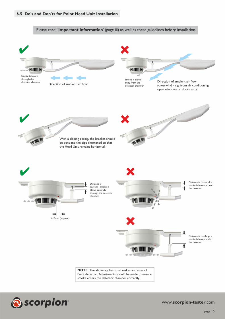
6.5 Do's and Don'ts for Point Head Unit Installation
Direction of ambient air flow.Direction of ambient air flow(crosswind - e.g. from air conditioning,open windows or doors etc.).
�� �
5-10mm (approx.)
�� �
�
Distance iscorrect - smoke isblown centrallythrough the detectorchamber
Distance is too small -smoke is blown aroundthe detector
Smoke is blownthrough thedetector chamber
Smoke is blownaway from thedetector chamber
NOTE: The above applies to all makes and sizes ofPoint detector. Adjustments should be made to ensuresmoke enters the detector chamber correctly.
�� �
With a sloping ceiling, the bracket shouldbe bent and the pipe shortened so thatthe Head Unit remains horizontal.
Please read: ' ' (page iii) as well as these guidelines before installation.Important Information
www. .comscorpion-tester
Distance is too large -smoke is blown underthe detector
scorpion®

page 16
1. Attach either the end cap presenter (Fig. 13 )A
or the sampling hole presenter ( ) to the ASDB
pipe as applicable. Use the double sided self-adhesive pads provided © or a suitable glue,to secure the presenter to the end cap or pipe.
2. Attach the flexible tube by pushing it firmlyinto the smoke presenter (Fig. 14).
NOTE: It is advisable to connect the cables to theHead Unit before proceeding (see Section 6.6).
3. Slide the head unit on to the bracket as far as itwill go (Fig. 16).
4. Attach the head unit and bracket assembly tothe pipe but do not lock the pipe clips at thisstage to allow for adjustment (Fig. 17).
5. Unscrew and remove the Fuel Breather Plugfrom the head unit (Fig. 18).
IMPORTANT: the head unit should nowbe kept horizontal with the label side facingupwards to prevent any fuel leakage.
6. Remove the Transport Pin (Fig. 18).: there are two parts to this pin. Turn partNote
D firmly in a clockwise direction while pullingoutwards. After removing part , turn partD E
anti-clockwise and pull out. Part isNote: D
designed to be tight and requires some effort toremove.
7. Attach the flexible tube by pushing it firmly intothe head unit and the smoke presenter (Fig. 19).
8. Finally, lock the pipe clips to secure the Scorpionbracket to the ASD pipe by squeezing the pipeand bracket as shown (Fig. 20).
www. .comscorpion-tester
6 6 Scorpion ASD Head Unit Installation.
���The Scorpion Head Unit is usually fitted to theend of a standard ASD pipe (not supplied) usingthe clips and smoke presenter provided(Fig. 13 ).A
���The Scorpion Head Unit can also be locatedadjacent to an air sampling hole along the lengthof an ASD pipe using the sampling holepresenter ( ).B
�� Ensure that the Scorpion smoke presenter is atight fit on the pipe or pipe end cap and thepresenter does not obstruct the air sampling hole.
Fig. 13
Please read: ' ' (page ii) as well as these guidelines before installation.Important Information
D
D
E
E
B
A
“CLICK”
Fig. 14
Fig. 17
Fig. 20
Fig. 18
Fig. 15
Fig. 16
Fig. 19
C
C
12mm
14mm
scorpion®
�� �
page 17
��
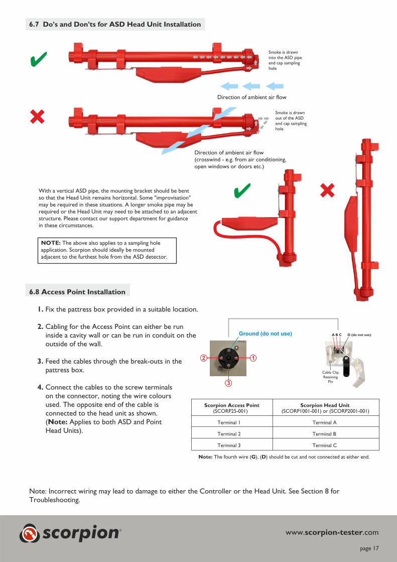
Direction of ambient air flow(crosswind - e.g. from air conditioning,open windows or doors etc.)
�
Smoke is drawninto the ASD pipeend cap samplinghole
Smoke is drawnout of the ASDend cap samplinghole
NOTE: The above also applies to a sampling holeapplication. Scorpion should ideally be mountedadjacent to the furthest hole from the ASD detector.
6.7 Do's and Don'ts for Head Unit InstallationASD
Direction of ambient air flow
With a vertical ASD pipe, the mounting bracket should be bentso that the Head Unit remains horizontal. Some "improvisation"may be required in these situations. A longer smoke pipe may berequired or the Head Unit may need to be attached to an adjacentstructure. Please contact our support department for guidancein these circumstances.
www. .comscorpion-tester
6.8 Access Point Installation
1. Fix the pattress box provided in a suitable location.
Cabling for the Access Point can either be run2.
inside a cavity wall or can be run in conduit on theoutside of the wall.
Feed the cables through the break-outs in the3.
pattress box.
Connect the cables to the screw terminals4.
on the connector, noting the wire coloursused. The opposite end of the cable isconnected to the head unit as shown.( Applies to both ASD and PointNote:
Head Units).
Note: Incorrect wiring may lead to damage to either the Controller or the Head Unit. See Section 8 forTroubleshooting.
Scorpion Access Point Scorpion Head Unit(SCORP25-001) (SCORP1001-001) or (SCORP2001-001)
Terminal 1 Terminal A
Terminal 2 Terminal B
Terminal 3 Terminal C
The fourth wire ( ), ( ) should be cut and not connected at either end.Note: G D
A B C D (do not use)
Cable ClipRetaining
Pin
12
3
Ground (do not use)
scorpion®
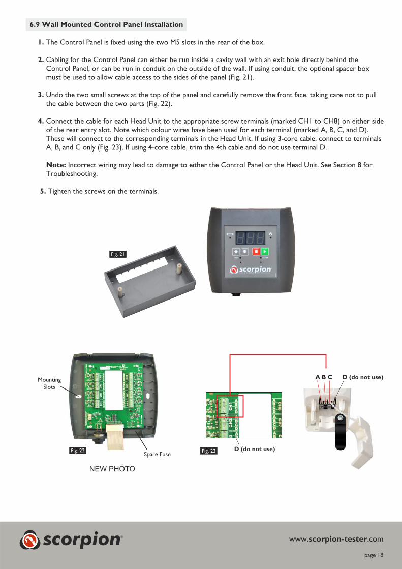
6.9 Wall Mounted InstallationControl Panel
1. The Control Panel is fixed using the two M5 slots in the rear of the box.
2. Cabling for the Control Panel can either be run inside a cavity wall with an exit hole directly behind theboxControl Panel, or can be run in conduit on the outside of the wall. If using conduit, the optional spacer
(Fig. 21)must be used to allow cable access to the sides of the panel .
3. Undo the two small screws at the top of the panel and carefully remove the front face, taking care not to pull(Fig. 22)the cable between the two parts .
4. Connect the cable for each Head Unit to the appropriate screw terminals (marked CH1 to CH8) on either sideof the rear entry slot. Note which colour wires have been used for each terminal (marked A, B, C, and D).These will connect to the corresponding terminals in the Head Unit. If using 3-core cable, connect to terminals
(Fig. 23) If using 4-core cable, trim the 4th cable and do not use terminal D.A, B, and C only .
oteN : Incorrect wiring may lead to damage to either the Control Panel or the Head Unit. See Section 8 forTroubleshooting.
5. Tighten the screws on the terminals.
page 18
Fig. 23
www. .comscorpion-tester
Fig. 21
MountingSlots
Fig. 22
A B C D (do not use)
Spare Fuse
scorpion®
NEW PHOTO
D (do not use)
7. Using Scorpion
page 19
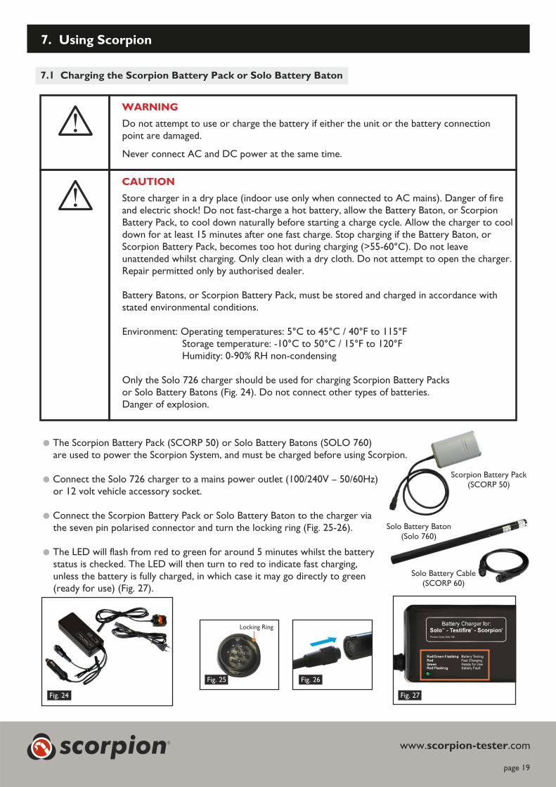
7 Charging the Scorpion Battery Pack or Solo Battery Baton.1
WARNING
Fig. 25 Fig. 26
Locking Ring
Scorpion Battery Pack(SCORP 50)
Solo Battery Baton(Solo 760)
www. .comscorpion-tester
Fig. 24 Fig. 27
���The Scorpion Battery Pack (SCORP 50) or Solo Battery Batons (SOLO 760)are used to power the Scorpion System, and must be charged before using Scorpion.
���Connect the Solo 726 charger to a mains power outlet (100/240V – 50/60Hz)or 12 volt vehicle accessory socket.
���Connect the Scorpion Battery Pack or Solo Battery Baton to the charger viathe seven pin polarised connector and turn the locking ring (Fig. 25-26).
���The LED will flash from red to green for around 5 minutes whilst the batterystatus is checked. The LED will then turn to red to indicate fast charging,unless the battery is fully charged, in which case it may go directly to green(ready for use) (Fig. 27).
Do not attempt to use or charge the battery if either the unit or the battery connectionpoint are damaged.
Never connect AC and DC power at the same time.
CAUTION
Store charger in a dry place (indoor use only when connected to AC mains). Danger of fireand electric shock! Do not fast-charge a hot battery, allow the Battery Baton, or ScorpionBattery Pack, to cool down naturally before starting a charge cycle. Allow the charger to cooldown for at least 15 minutes after one fast charge. Stop charging if the Battery Baton, orScorpion Battery Pack, becomes too hot during charging (>55-60°C). Do not leaveunattended whilst charging. Only clean with a dry cloth. Do not attempt to open the charger.Repair permitted only by authorised dealer.
Battery Batons, or Scorpion Battery Pack, must be stored and charged in accordance withstated environmental conditions.
Environment: Operating temperatures: 5°C to 45°C / 40°F to 115°FStorage temperature: -10°C to 50°C / 15°F to 120°FHumidity: 0-90% RH non-condensing
Only the Solo 726 charger should be used for charging Scorpion Battery Packsor Solo Battery Batons (Fig. 24). Do not connect other types of batteries.Danger of explosion.
scorpion®
Solo Battery Cable(SCORP 60)
page 20
www. .comscorpion-tester
���After fast charging is complete (90 minutes for a fully discharged battery), the charge is automatically converted toa trickle charge and the LED turns to green (ready for use).
���A red flashing LED indicates a faulty battery. Disconnect the battery from the charger and replace with a newbattery.
���The battery charger and battery can remain connected under a trickle charge for several hours without damageto the battery. This maintains the battery in a fully charged state, ready for use.
Note: If the battery is not to be used for some time (i.e. within the next day), it is advisable to unplug the chargerfrom the power supply.
���To stop charging, disconnect the power plug before removing the battery from the charger.
���To obtain the maximum battery life, the Scorpion Battery Pack or Solo Battery Baton should be fully dischargedbefore recharging when possible.
11. Using Scorpion7 2 Connecting the Battery.
���With a Scorpion Battery Pack (SCORP 50), insert the connector at the end of the Battery Pack to the socketat the bottom of the Scorpion Portable Controller or the Wall Mounted Controller. The connectors need tobe aligned before they can push together. Once inserted, twist the collar on the battery socket clockwise tolock the battery into place.
���To remove the battery, twist the collar anti-clockwise to unlock, then pull gently to disengage.
���When using a Solo Battery Baton (SOLO 760), a Scorpion Battery Cable (SCORP 60) is required to connectthe battery baton to the Scorpion Portable Controller or Wall Mounted Controller.
7 3 Setting SMOKE and CLEAR Times on the Scorpion Portable Controller.
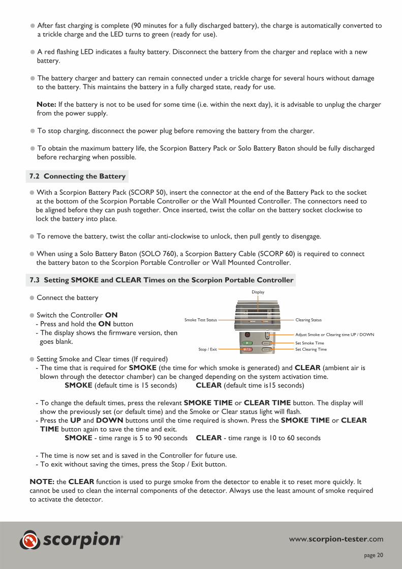
���Connect the battery
�� Switch the Controller ON
- Press and hold the buttonON
- The display shows the firmware version, thengoes blank.
�� Setting Smoke and Clear times (If required)- The time that is required for (the time for which smoke is generated) and (ambient air isSMOKE CLEAR
blown through the detector chamber) can be changed depending on the system activation time.(default time is 15 seconds) (default time is15 seconds)SMOKE CLEAR
- To change the default times, press the relevant or button. The display willSMOKE TIME CLEAR TIME
show the previously set (or default time) and the Smoke or Clear status light will flash.- Press the and buttons until the time required is shown. Press the orUP DOWN SMOKE TIME CLEAR
TIME button again to save the time and exit.SMOKE CLEAR- time range is 5 to 90 seconds - time range is 10 to 60 seconds
- The time is now set and is saved in the Controller for future use.- To exit without saving the times, press the Stop / Exit button.
NOTE: CLEARthe function is used to purge smoke from the detector to enable it to reset more quickly. Itcannot be used to clean the internal components of the detector. Always use the least amount of smoke requiredto activate the detector.
Display
Clearing Status
Adjust Smoke or Clearing time UP / DOWN
Set Smoke Time
Set Clearing Time
Smoke Test Status
Stop / Exit
scorpion®

page 21
www. .comscorpion-tester
7 4 Setting TEST and CLEAR Times on the Wall Mounted Control Panel.
���The time that is required for (the time for which smoke is generated) and (ambient air isTEST CLEAR
blown through the detector chamber) can be changed depending on the system activation time.
(default time is 15 seconds)TEST
(default time is 15 seconds)CLEAR
���Press and hold the relevant or recessed button with a small blunt tool.TEST CLEAR
���The corresponding LED will start to flash.
���Press the button to increase the time or theUP DOWN
button to decrease the time. The time is shown on the display.
- time range is 5 to 90 secondsTEST
- time range is 10 to 60 secondsCLEAR
���When the required time is shown, release the or recessed button. The time is now set and isTEST CLEAR
saved in the Control Panel for future use. This time is used for all the Head Units connected to that panel.
NOTE: CLEARthe function is used to purge smoke from the detector to enable it to reset more quickly. Itcannot be used to clean the internal components of the detector.
TEST CLEAR
R E M O T E D E T E C T O R
scorpionT E S T T E C H N O L O G Y
®
0 0 0START Button
STOP Button
Clearing Indicator
UP Button
DOWN Button
Smoke Test Indicator
Clearing Time Button(recessed)
Smoke Time Button(recessed)
7 5.1 Enabling the Transport Timer.
���The Transport Time is used in ASD systems, and is the time taken between the start of smoke generation andthe event appearing on the ASD panel.
���The Timer is activated / deactivated by pressing and holding the button for 3 seconds (bothSTOP
Controllers).
���The Timer Indicator LED flashes fast 3 times to show the timer has been activated, and flashes slowly for3 times when deactivated.
���During a test cycle, the Timer Indicator LED is illuminated and the display shows the time since the start ofsmoke generation (counting up).
scorpion®
page 22
www. .comscorpion-tester
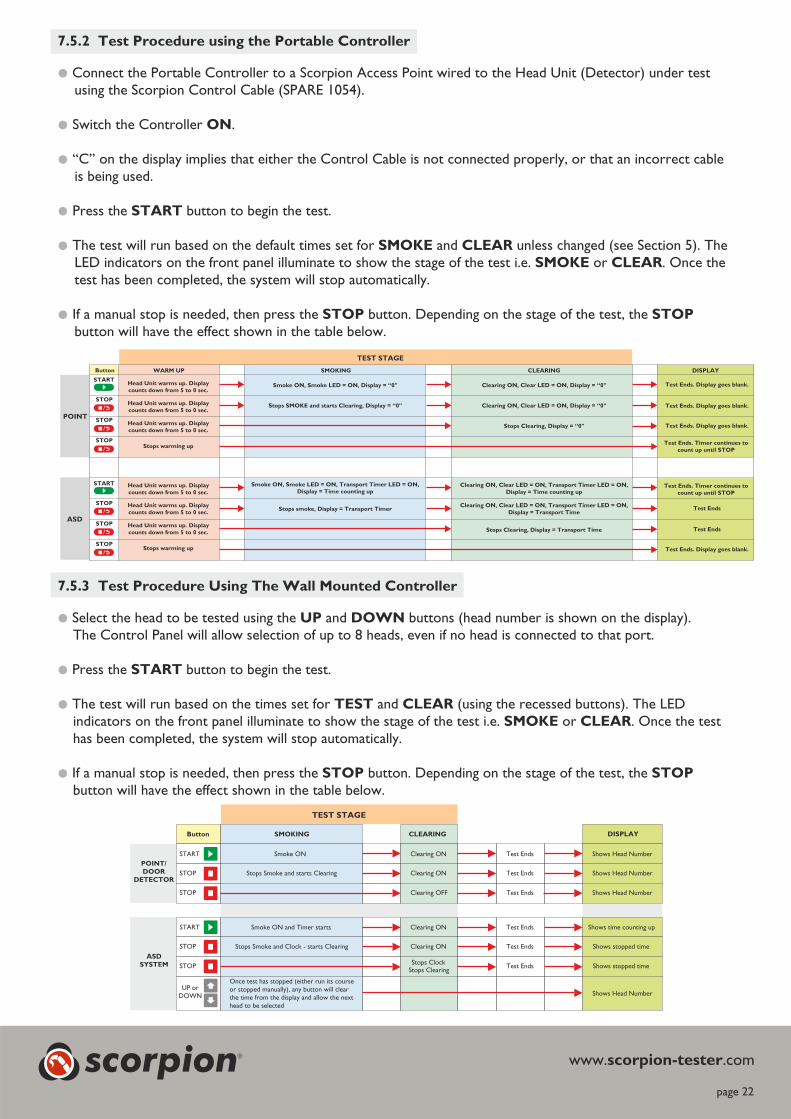
7 5.2 Test Procedure using the Portable Controller.
���Connect the Portable Controller to a Scorpion Access Point wired to the Head Unit (Detector) under testusing the Scorpion Control Cable (SPARE 1054).
�� Switch the Controller .ON
�� “C” on the display implies that either the Control Cable is not connected properly, or that an incorrect cableis being used.
�� Press the button to begin the test.START
�� The test will run based on the default times set for and unless changed (see Section 5). TheSMOKE CLEAR
LED indicators on the front panel illuminate to show the stage of the test i.e. or . Once theSMOKE CLEAR
test has been completed, the system will stop automatically.
�� If a manual stop is needed, then press the button. Depending on the stage of the test, theSTOP STOP
button will have the effect shown in the table below.
POINT
ASD
WARM UPButton SMOKING
TEST STAGE
CLEARING
START
STOP
STOP
STOP
START
STOP
STOP
STOP
Smoke ON, Smoke LED = ON, Display = “0"
Stops SMOKE and starts Clearing, Display = “0"
Smoke ON, Smoke LED = ON, Transport Timer LED = ON,
Display = Time counting up
Stops smoke, Display = Transport Timer
Clearing ON, Clear LED = ON, Display = “0"
Clearing ON, Clear LED = ON, Display = “0"
Clearing ON, Clear LED = ON, Transport Timer LED = ON,
Display = Time counting up
Stops Clearing, Display = Transport Time
Stops Clearing, Display = “0"
Clearing ON, Clear LED = ON, Transport Timer LED = ON,
Display = Transport Time
Head Unit warms up. Display
counts down from 5 to 0 sec.
Head Unit warms up. Display
counts down from 5 to 0 sec.
Head Unit warms up. Display
counts down from 5 to 0 sec.
Stops warming up
Test Ends. Display goes blank.
Test Ends. Timer continues to
count up until STOP
Test Ends. Timer continues to
count up until STOP
Test Ends
Test Ends
Head Unit warms up. Display
counts down from 5 to 0 sec.
Head Unit warms up. Display
counts down from 5 to 0 sec.
Head Unit warms up. Display
counts down from 5 to 0 sec.
Stops warming up
7 5.3 Test Procedure Using The Wall Mounted Controller.
���Select the head to be tested using the and buttons (head number is shown on the display).UP DOWN
The Control Panel will allow selection of up to 8 heads, even if no head is connected to that port.
���Press the button to begin the test.START
���The test will run based on the times set for and (using the recessed buttons). The LEDTEST CLEAR
indicators on the front panel illuminate to show the stage of the test i.e. or . Once the testSMOKE CLEAR
has been completed, the system will stop automatically.
���If a manual stop is needed, then press the button. Depending on the stage of the test, theSTOP STOP
button will have the effect shown in the table below.
TEST STAGE
Button
POINT/
DOOR
DETECTOR
ASD
SYSTEM
START
STOP
STOP
START
STOP
STOP
SMOKING CLEARING
Smoke ON
Stops Smoke and starts Clearing
Clearing ON
Clearing ON
Clearing OFF
Test Ends
Test Ends
Test Ends
Shows Head Number
Shows Head Number
Shows Head Number
Test Ends
Test Ends
Test Ends
Shows time counting up
Shows stopped time
Shows stopped time
Smoke ON and Timer starts
Stops Smoke and Clock - starts Clearing
Clearing ON
Clearing ON
Stops ClockStops Clearing
Shows Head Number
Once test has stopped (either run its courseor stopped manually), any button will clearthe time from the display and allow the nexthead to be selected
UP orDOWN
DISPLAY
DISPLAY
scorpion®
Test Ends. Display goes blank.
Test Ends. Display goes blank.
Test Ends. Display goes blank.

7 6 Warnings and Errors.
���Battery Status Indicator - Glows red when battery level is low. Glows green when the level is ok.Tests cannot made when the LED glows red and the battery will need to be recharged.
���Error - Three flashing points on the display indicate that a fault has occurred and the Control Panel fuse hasblown (see Section 9).
�� Scorpion has a clearing function that blows air through the detector to clear the smoke more quickly. This ispart of the standard test profile (unless stopped manually). If the alarm keeps sounding, the clearing time maynot be long enough and can be increased.
For future tests, try reducing the smoke time to lessen the amount of smoke in the detector chamber.��
page 23
www. .comscorpion-testerscorpion®

8. Troubleshooting
page 24
www. .comscorpion-tester
Scorpion not working
Control Panel ONler /(are any lights on?)
Ensure battery is fullycharged and properly
plugged in. No
Is atteryB StatusLED glowing red?
Ensure battery is fullycharged, or try another
battery.
Does displayshow anything ?
If display shows flashingpoints, this indicates a fault
has caused the internalfuse to blow. Check circuit
and replace fuse.
Is the correct portselected?
Is a light visiblethrough the mesh in
the head?
Check tthat he wiring fromthe Access Point / Control Panel
to the Head Unit is correct,conductors are properly inthe terminals, conductorsare not broken, and cableis within CSA and length
specification.
At this stage, the PortableController looks like it is
working correctly.
Is the eadH Unitmounted correctly?
Refer to Section 6.Check Head isUnit
, breather plugs(top and nose) removed,
tube connected,no blockages?
Is smoke coming outof the head nozzle?
Scorpion is then working.Check the alignment of
the smoke nozzle with thedetector (smoke going
into detector) (Section 6),increase the smoke time
(Section 7.3) to activateyour detector, or follow
the detector s’troubleshooting guide.
Replace the eadH Unit.
No
No
No
Yes
Yes
Yes
Yes
Yes Yes
Yes
No
No
No
0 0. . .0
horizontal
At this stage, the Wall MountedControl Panel looks like it is
working correctly .
Control Panel CH 1
connects to Head 1,Display = “1”, check
correctly wired .
A B C D (do not use)
I hes t
Portable Controller Wall MountedController
12
3
Ground (do not use)
Ensure Portable Controlleris switched on.
The Controller does notdetect the presence of ahead, so will still allow a“test” to be run on an
unused port. Ensure thepatch cable is connected
at both the PortableController and Access
Point. Ensure the correcthead is selected on theWall Mounted Control
Panel.
scorpion®
‘C’ indicates a fault withthe yellow Control Cable.

9. Service and Maintenance
9.1 Scorpion Head Units
���There are no user serviceable parts in the Scorpion Head Unit which is permanently sealed.
���Any attempt to open or tamper with the Scorpion Head Unit will invalidate any warranty or liability withNo Climb Products Ltd.
NOTE: The Head Unit is designed to be permanently installed providing in excess of 240 tests of 15 seconds each.
9.2 Scorpion Portable Controller and Wall Mounted Control Panel
���The Portable Controller contains a 500mA fuse (5 x 20mm cartridge type) which can be replaced if necessary.
�� The Control Cable (yellow) can be replaced using Part No. SPARE 1054-001.
���The Wall Mounted Control Panel contains a 500mA fuse (Littlefuse Omni-Block 500mA Farnell Part No. 9943625, orequivalent) which can be replaced if necessary. One spare fuse supplied with each Control Panel.
���There are no other user serviceable components in the Portable Controller or the Wall Mounted Control Panel.
9.3 Batteries and Battery Charger
���There are no user-servicable parts in the Scorpion Battery Pack (SCORP 50-001) or the Solo Battery Baton (Solo 760-001),or in the Solo Charger (Solo 726).
�� Any attempt to open or tamper with the batteries, charger, or any other approved Scorpion (or Solo) component willinvalidate any warranty or liability with No Climb Products Ltd.
Disposal of old product
See WEEE statement (page 5).
page 25
www. .comscorpion-testerscorpion®

10. Technical Specification
���Safety features
• Scorpions energized only at time of test• Isolation between Scorpion circuit and detection system
ion circuit• Internal over-current protection on Scorp• Battery over-current cut-out
���Power source and charge data
Battery Pack (SCORP 50) -• Scorpion NiMH rechargeable nominal 7.2v 2.2Ah• S NiMH rechargeable nominal 7.2v 2.2Aholo Battery Baton (Solo 760) -
using Solo-726 charger• Charging time 75 - 90 minutes (when completely discharged)• Solo Battery Charger (Solo 726) - Input: 100-240V AC / 50/60 Hz / 0.44A
- Output: 8.4V DC 2A FAST
���Servicing intervals
• None requiredHead Unit• Scorpion sealed for life (no serviceable or field replaceable parts)
• S rpion Portable and Wall Mounted Controllers contains a fuseco
���Cabling
• Maximum conductor size is 1.5mm , minimum is 0.5mm2 2
5• Scorpion circuit wiring: FP200 1.5mm , Lapp J-Y(ST) Y0. mm , or equivalent2 2
• Maximum cable length per Scorpion Control Panel - 100 metres(1)
Access Point 1 / per Wall Mounted Control Panel - 8• Maximum Scorpions per -
���Testing Capacity
• In excess of 240 tests of 15 seconds each per Scorpion Head Unit
(1) Depends on cable used (see Section 6.7).
���Environment
page 26
Scorpion Battery Pack Scorpion Head Unit Scorpion Controllers
Transport / Storage -20 C to +35 C -10 C to 50 C -10 C to 50 C° ° ° ° ° °Temperature (-4 F to +95 F) (14 F to 122 F) (14 F to 122 F)° ° ° ° ° °
Storage Humidity 0-90% RH 0-90% RH 0-90% RH(non-condensing) (non-condensing) (non-condensing)
Operating Temperature +5 C to +45 C 0 C to 60 C +5 C to 45 C° ° ° ° ° °(41 F to 113 F) (32 F to 140 F) (41 F to 113 F)° ° ° ° ° °
Operating Humidity 0-85% RH 0-95% RH 0-85% RH(non-condensing) (non-condensing) (non-condensing)
Ingress Protection IP40 IP20 IP40
Weights & Dimensions 523g <200g <500g139mm (W) x 81mm (L) x 48mm (H) 1 5mm (W) x 54mm (L) x 34mm (H) 1 mm (W) x mm (L) x mm (H)5 00 225 40
(excluding nozzle) [Portable Controller]
155m 150m 37mm (W) x m (L) x m (H)[Wall Mounted Controller]
Note: The Scorpion system is designed for specific applications within the above parameters. For additional information regardinglocation and installation procedures, please refer to the Scorpion User Manual and Quick Start Guide at: www.scorpion-tester.com
www. .comscorpion-testerscorpion®
: 13.8V DC 1.8A
: 8.4V DC 100mA TRICKLE
11. Technical Support
For support, service and further information, please contact:
No Climb Products Ltd
Edison House, 163 Dixons Hill Road, Welham Green, Herts, AL9 7JE United KingdomTel: +44 (0) 1707 282760 Fax: +44 (0) 1707 282777Email: [email protected]
Online help available at www.scorpion-tester.com/support
page 27
www. .comscorpion-testerscorpion®

As our policy is one of continuous improvement, details of productsdescribed within this publication are subject to change withoutnotice. All information provided here is believed to be correct at thetime of going to press. Every effort has been made to ensure theaccuracy of information which is provided in good faith but nothingcontained herein is intended to incorporate any representation orwarranty, either express or implied or to form the basis of any legalrelations between the parties hereto, additional to or in lieu of suchas may be applicable to a contract of sale or purchase.
All Rights Reserved. No part of these writtenCopyright Notice:
materials may be reproduced or used in any form or by any means,electronic or mechanical, including photocopying without the priorwritten permission of .testers, No Climb Products Ltddetector
No liability is assumed with the respect to the use of informationcontained in these written materials or software, or for damagesresulting from use of the information contained therein.
No Climb Products Ltd
Edison House163 Dixons Hill RoadWelham GreenHertfordshire AL9 7JEUnited Kingdom
Tel: +44 (0) 1707 282 760Fax: +44 (0) 1707 282 777
[email protected] LI32344-3
www. .comscorpion-tester