remote i/o product specification · remote i/o product specification 5 3. digital input/output 3.1...
TRANSCRIPT

Remote I/O Product Specification

Table of Contents
1. Product Overview ................................................................................................... 1 Product List: ................................................................................................... 1 1.1
Coupler List: ........................................................................................... 1 1.1.1 Digital I/O List: ........................................................................................ 1 1.1.2 Analog I/O List: ....................................................................................... 1 1.1.3 Motion List: ............................................................................................ 1 1.1.4
2. Fieldbus Coupler ..................................................................................................... 2 CANopen Specifications ................................................................................. 2 2.1 Ethernet TCP/IP Specifications ....................................................................... 3 2.2 EtherCAT Specifications .................................................................................. 4 2.3
3. Digital Input/Output ............................................................................................... 5 Digital Input / Output Modules ...................................................................... 5 3.1 Digital Input Specifications ............................................................................ 5 3.2 Digital Output Specifications.......................................................................... 5 3.3 Wiring ............................................................................................................. 6 3.4
4. Analog Input/Output .............................................................................................. 7 Analog Input / Output Modules ..................................................................... 7 4.1 Analog Input Specification ............................................................................. 7 4.2 Analog Output Specification .......................................................................... 7 4.3 Wiring ............................................................................................................. 8 4.4
5. Temperature ......................................................................................................... 10 Temperature Module ................................................................................... 10 5.1 Temperature Specification ........................................................................... 10 5.2 Wiring ........................................................................................................... 11 5.3
6. Motion Control ..................................................................................................... 12 Modules Specifications ................................................................................ 12 6.1 Digital Input Specifications .......................................................................... 12 6.2 Digital Output Specifications........................................................................ 12 6.3 Wiring ........................................................................................................... 12 6.4
7. Dimensions ........................................................................................................... 14 iR-COP .......................................................................................................... 14 7.1 iR-ETN ........................................................................................................... 15 7.2 iR-ECAT ......................................................................................................... 16 7.3 iR-DM16-N & P, iR-DQ16-N&P, iR-DI16-K, iR-DQ08-R, iR-PU01-P ................ 17 7.4 iR-AI04-VI, iR-AM06-VI, iR-AQ04-VI, iR-AI04-TR .......................................... 18 7.5
8. Power Consumption ............................................................................................. 19
Remote I/O Product Specification
1
www.weintek.com
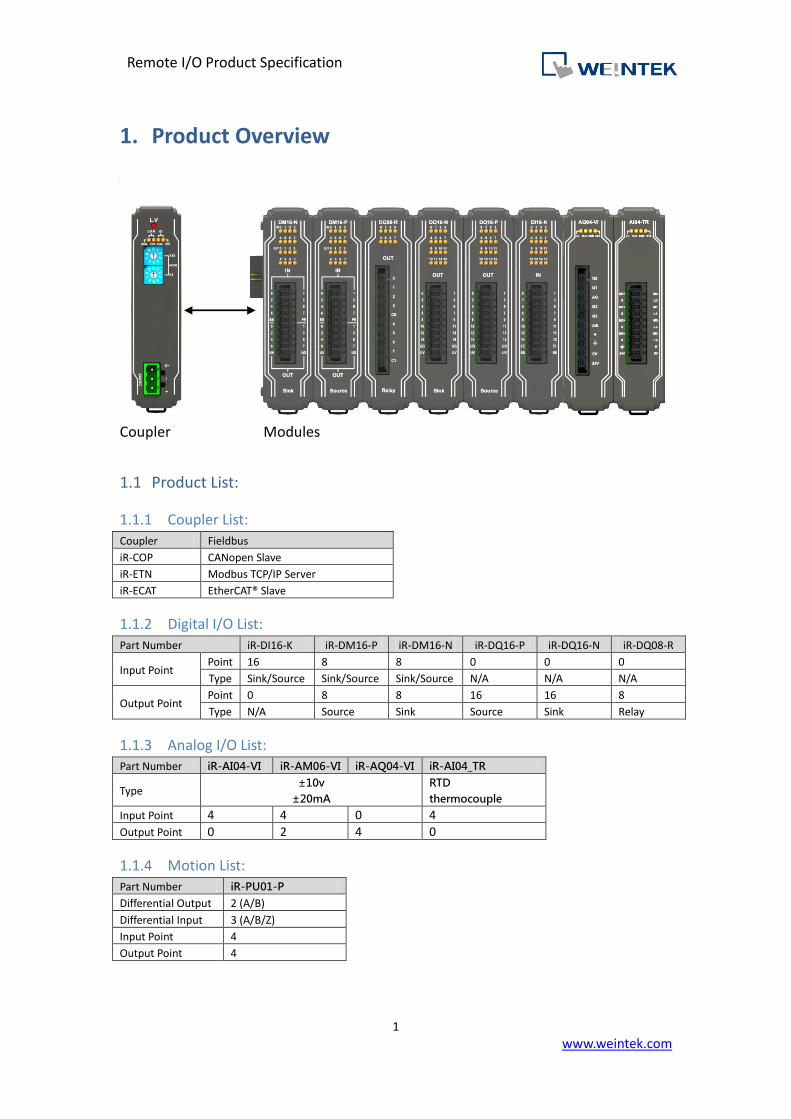
1. Product Overview
Coupler Modules
Product List: 1.1
Coupler List: 1.1.1
Coupler Fieldbus
iR-COP CANopen Slave
iR-ETN Modbus TCP/IP Server
iR-ECAT EtherCAT® Slave
Digital I/O List: 1.1.2
Part Number iR-DI16-K iR-DM16-P iR-DM16-N iR-DQ16-P iR-DQ16-N iR-DQ08-R
Input Point Point 16 8 8 0 0 0
Type Sink/Source Sink/Source Sink/Source N/A N/A N/A
Output Point Point 0 8 8 16 16 8
Type N/A Source Sink Source Sink Relay
Analog I/O List: 1.1.3Part Number iR-AI04-VI iR-AM06-VI iR-AQ04-VI iR-AI04_TR
Type ±10v
±20mA
RTD
thermocouple
Input Point 4 4 0 4
Output Point 0 2 4 0
Motion List: 1.1.4Part Number iR-PU01-P
Differential Output 2 (A/B)
Differential Input 3 (A/B/Z)
Input Point 4
Output Point 4

Remote I/O Product Specification
2
www.weintek.com
2. Fieldbus Coupler
CANopen Specifications 2.1Communication Interface Specifications Model iR-COP
Expansion I/O
Module
No. of Bus Terminals Depends on Power Consumption
Digital Input Point Max. 256
Digital Output Point Max. 128
Analog Input Channel Max. 64
Analog Output Channel Max. 64
Indicators
CAN RUN (Green) CANopen Status Indicator
CAN ERR (Red) CANopen Error Indicator
L.V (Red ) Low Voltage Status Indicator
IO RUN (Green) Module Status Indicator
IO ERR (Red) Module Error Indicator
Data Transfer Rate 1M 800k 500k 250k 125k 100k 50k
Length of the Cable 20m 50m 100m 250m 500m 600m 1,000m
Node ID 1~99
Number of PDOs
(CANopen) 8 Transmit PDOs / 8 Receive PDOs
Process Data
Operating Modes synchronous, event-driven ,event timer, polling
Number of SDOs
Available 1 Standard SDOs
Bus Connection 1 x open style connector, 5-pole, plug included
Additional CANopen
Features
life/node guarding, heartbeat, emergency object, variables mapping, store/restore, output
error mode.
General Specification
Power
Power Supply 24 VDC (-15%/+20%)
Power Dissipation Nominal 100mA@24VDC
Current for Internal Bus Max 2A@5VDC
Current Consumption 170mA@5VDC
Electrical Isolation Isolated CANopen : Yes
Isolated power : Yes
Back-up Fuse ≤ 1.6A Self-recovery
Specification
PCB Coating Yes
Enclosure Plastic
Dimensions WxHxD 27 x 109 x 81 mm
Weight Approx. 0.15 kg
Mount 35mm DIN rail mounting
Environment
Protection Structure IP20
Storage Temperature -20° ~ 70°C (-4° ~ 158°F)
Operating Temperature 0° ~ 55°C (32° ~ 131°F)
Relative Humidity 10% ~ 90% (non-condensing)
Connection Cross-section 0.5 mm² ... 2.5 mm², stranded, solid wire, AWG 26-12
Certification EMC Immunity
Conforms to
EN 55032: 2012+AC: 2013, Class A
EN 61000-6-4: 2007+A1:2011
EN 55024: 2010+A1: 2015
EN 61000-6-2:2005
Remote I/O Product Specification
3
www.weintek.com
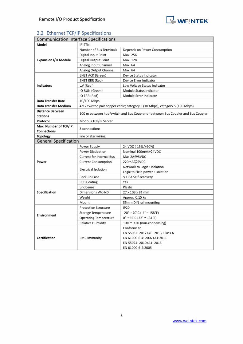
Ethernet TCP/IP Specifications 2.2Communication Interface Specifications Model iR-ETN
Expansion I/O Module
Number of Bus Terminals Depends on Power Consumption
Digital Input Point Max. 256
Digital Output Point Max. 128
Analog Input Channel Max. 64
Analog Output Channel Max. 64
Indicators
ENET ACK (Green) Device Status Indicator
ENET ERR (Red) Device Error Indicator
L.V (Red ) Low Voltage Status Indicator
IO RUN (Green) Module Status Indicator
IO ERR (Red) Module Error Indicator
Data Transfer Rate 10/100 Mbps
Data Transfer Medium 4 x 2 twisted pair copper cable; category 3 (10 Mbps), category 5 (100 Mbps)
Distance Between
Stations 100 m between hub/switch and Bus Coupler or between Bus Coupler and Bus Coupler
Protocol Modbus TCP/IP Server
Max. Number of TCP/IP
Connections 8 connections
Topology line or star wiring
General Specification
Power
Power Supply 24 VDC (-15%/+20%)
Power Dissipation Nominal 100mA@24VDC
Current for Internal Bus Max 2A@5VDC
Current Consumption 220mA@5VDC
Electrical Isolation Network to Logic : Isolation
Logic to Field power : Isolation
Back-up Fuse ≤ 1.6A Self-recovery
Specification
PCB Coating Yes
Enclosure Plastic
Dimensions WxHxD 27 x 109 x 81 mm
Weight Approx. 0.15 kg
Mount 35mm DIN rail mounting
Environment
Protection Structure IP20
Storage Temperature -20° ~ 70°C (-4° ~ 158°F)
Operating Temperature 0° ~ 55°C (32° ~ 131°F)
Relative Humidity 10% ~ 90% (non-condensing)
Certification EMC Immunity
Conforms to
EN 55032: 2012+AC: 2013, Class A
EN 61000-6-4: 2007+A1:2011
EN 55024: 2010+A1: 2015
EN 61000-6-2:2005
Remote I/O Product Specification
4
www.weintek.com
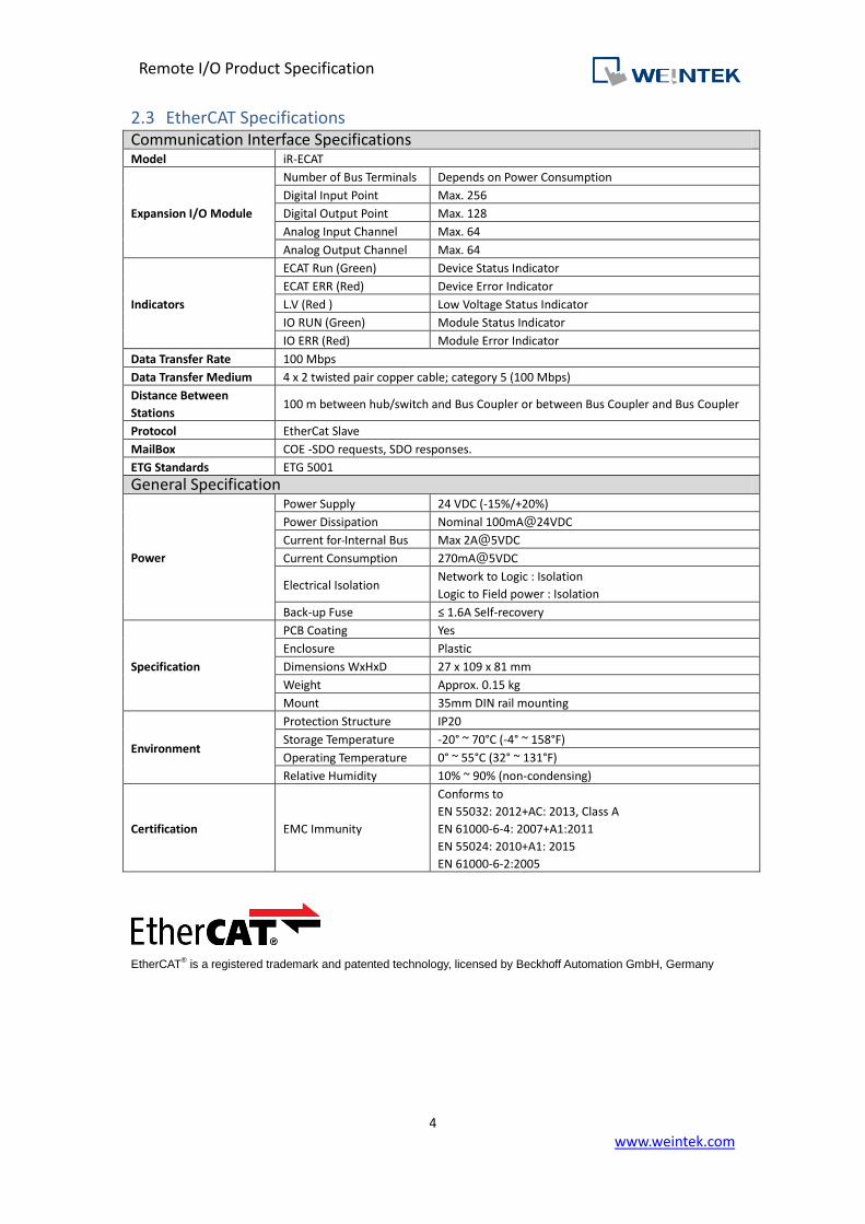
EtherCAT Specifications 2.3Communication Interface Specifications Model iR-ECAT
Expansion I/O Module
Number of Bus Terminals Depends on Power Consumption
Digital Input Point Max. 256
Digital Output Point Max. 128
Analog Input Channel Max. 64
Analog Output Channel Max. 64
Indicators
ECAT Run (Green) Device Status Indicator
ECAT ERR (Red) Device Error Indicator
L.V (Red ) Low Voltage Status Indicator
IO RUN (Green) Module Status Indicator
IO ERR (Red) Module Error Indicator
Data Transfer Rate 100 Mbps
Data Transfer Medium 4 x 2 twisted pair copper cable; category 5 (100 Mbps)
Distance Between
Stations 100 m between hub/switch and Bus Coupler or between Bus Coupler and Bus Coupler
Protocol EtherCat Slave
MailBox COE -SDO requests, SDO responses.
ETG Standards ETG 5001
General Specification
Power
Power Supply 24 VDC (-15%/+20%)
Power Dissipation Nominal 100mA@24VDC
Current for Internal Bus Max 2A@5VDC
Current Consumption 270mA@5VDC
Electrical Isolation Network to Logic : Isolation
Logic to Field power : Isolation
Back-up Fuse ≤ 1.6A Self-recovery
Specification
PCB Coating Yes
Enclosure Plastic
Dimensions WxHxD 27 x 109 x 81 mm
Weight Approx. 0.15 kg
Mount 35mm DIN rail mounting
Environment
Protection Structure IP20
Storage Temperature -20° ~ 70°C (-4° ~ 158°F)
Operating Temperature 0° ~ 55°C (32° ~ 131°F)
Relative Humidity 10% ~ 90% (non-condensing)
Certification EMC Immunity
Conforms to
EN 55032: 2012+AC: 2013, Class A
EN 61000-6-4: 2007+A1:2011
EN 55024: 2010+A1: 2015
EN 61000-6-2:2005
EtherCAT
® is a registered trademark and patented technology, licensed by Beckhoff Automation GmbH, Germany
Remote I/O Product Specification
5
www.weintek.com
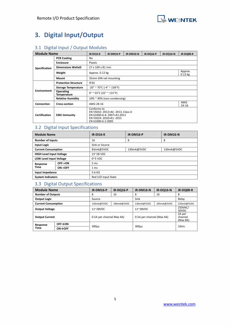
3. Digital Input/Output
Digital Input / Output Modules 3.1Module Name iR-DI16-K iR-DM16-P iR-DM16-N iR-DQ16-P iR-DQ16-N iR-DQ08-R
Specification
PCB Coating No
Enclosure Plastic
Dimensions WxHxD 27 x 109 x 81 mm
Weight Approx. 0.12 kg Approx. 0.13 kg
Mount 35mm DIN rail mounting
Environment
Protection Structure IP20
Storage Temperature -20° ~ 70°C (-4° ~ 158°F)
Operating Temperature 0° ~ 55°C (32° ~ 131°F)
Relative Humidity 10% ~ 90% (non-condensing)
Connection Cross-section AWG 28-16 AWG 24-16
Certification EMC Immunity
Conforms to EN 55032: 2012+AC: 2013, Class A EN 61000-6-4: 2007+A1:2011 EN 55024: 2010+A1: 2015 EN 61000-6-2:2005
Digital Input Specifications 3.2
Module Name iR-DI16-K iR-DM16-P iR-DM16-N
Number of Inputs 16 8 8
Input Logic Sink or Source
Current Consumption 83mA@5VDC 130mA@5VDC 130mA@5VDC
HIGH Level Input Voltage 15~28 VDC
LOW Level Input Voltage 0~5 VDC
Response Time
OFF->ON 5 ms
ON->OFF 1 ms
Input Impedance 5.6 KΩ
System Indicators Red LED Input State
Digital Output Specifications 3.3Module Name iR-DM16-P iR-DQ16-P iR-DM16-N iR-DQ16-N iR-DQ08-R Number of Outputs 8 16 8 16 8
Output Logic Source Sink Relay
Current Consumption 130mA@5VDC 196mA@5VDC 130mA@5VDC 205mA@5VDC 220mA@5VDC
Output Voltage 11~28VDC 11~28VDC 250VAC/ 30VDC
Output Current 0.5A per channel Max 4A) 0.5A per channel (Max 4A) 2A per channel (Max 8A)
Response Time
OFF→ON 300μs 300μs 10ms
ON→OFF


Remote I/O Product Specification
7
www.weintek.com
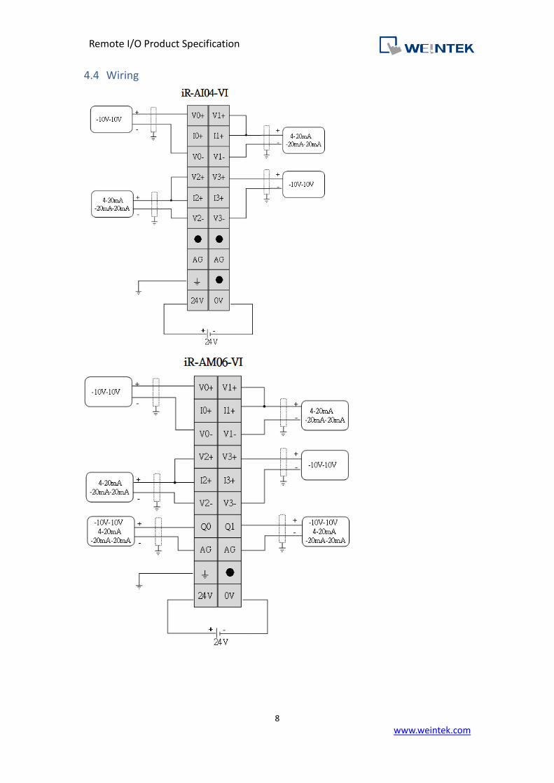
4. Analog Input/Output
Analog Input / Output Modules 4.1Module Name iR-AI04-VI iR-AM06-VI iR-AQ04-VI Number of Analog Inputs 4 (±10V/ ±20mA) 4 (±10V/ ±20mA) 0
Number of Analog outputs 0 2 (±10V/ ±20mA) 4 (±10V/ ±20mA)
Current Consumption 70mA@5VDC 70mA@5VDC 65mA@5VDC
Analog Power Supply 24 VDC(20.4 VDC~28.8 VDC)(-15%~+20%)
Specification
PCB Coating Yes
Enclosure Plastic
Dimensions WxHxD 27 x 109 x 81 mm
Weight Approx. 0.12 kg
Mount 35mm DIN rail mounting
Environment
Protection Structure IP20
Storage Temperature -20° ~ 70°C (-4° ~ 158°F)
Operating Temperature 0° ~ 55°C (32° ~ 131°F)
Relative Humidity 10% ~ 90% (non-condensing)
Connection Cross-section AWG 28-16 AWG 24-16
Certification EMC Immunity
Conforms to EN 55032: 2012+AC: 2013, Class A EN 61000-6-4: 2007+A1:2011 EN 55024: 2010+A1: 2015 EN 61000-6-2:2005
Analog Input Specification 4.2Input Range -10V~10V、 -20mA~20mA
Conversion Time 2ms/Channel
Isolation 500 VDC:(Analog / Digital)
Data Format -10~10V -5V~5V 1~5V -20~20mA 4~20mA
±32000 ±32000 0~32000 ±32000 0~32000
Resolution 0.312mV 0.156mV 0.156mV 0.625uA 0.625uA
16 bit 16 bit 15 bit 16 bit 15 bit
Input Impedance 1MΩ 250 Ω
Diagnose Supply Voltage Wire break (1~5V & 4~20mA) Overflow/underflow
Accuracy ± 0.2 % Full Scale@25°C ± 0.3 % Full Scale@0° ~ 55°C
Analog Output Specification 4.3Output Range -10V~10V、-20mA~20mA
Conversion Time
1.6ms/4 channels
1.3ms/3 channels
1ms/2 channels
700us/1 channel
Isolation 500 VDC:(Analog / Digital)
Data Format -10~10V -5V~5V 1~5V -20~20mA 4~20mA
±32000 ±32000 0~32000 ±32000 0~32000
Resolution 5mV 5mV 5mV 10uA 10uA
12bit 11bit 10bit 12bit 11bit
Output Impedance ≧1kΩ ≦500Ω
Diagnose Supply Voltage Wire break
Accuracy ± 0.2 % Full Scale@25°C ± 0.3 % Full Scale@0° ~ 55°C

Remote I/O Product Specification
10
www.weintek.com
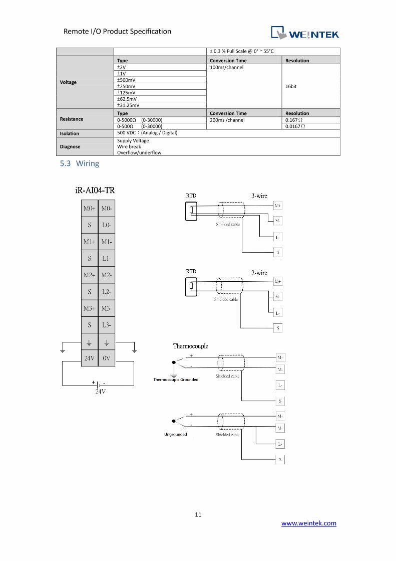
5. Temperature
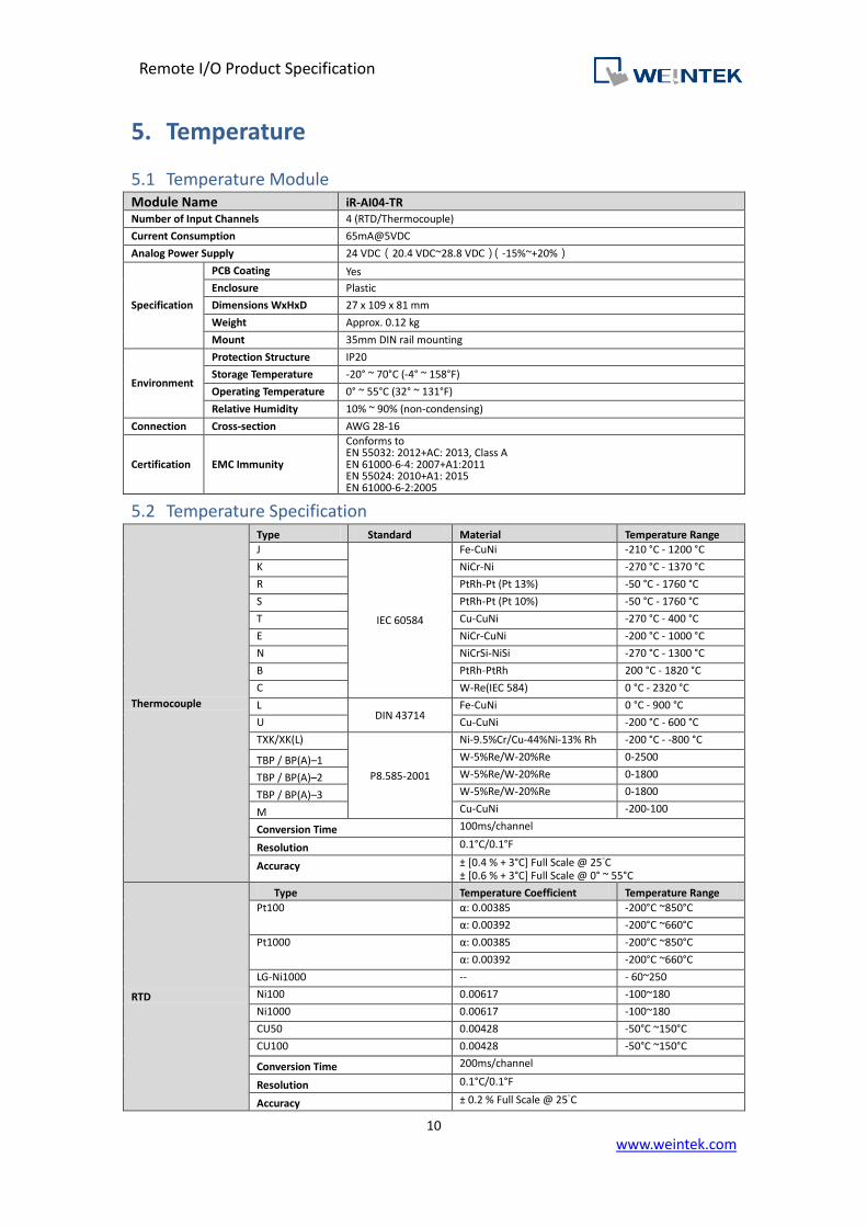
Temperature Module 5.1Module Name iR-AI04-TR Number of Input Channels 4 (RTD/Thermocouple)
Current Consumption 65mA@5VDC
Analog Power Supply 24 VDC(20.4 VDC~28.8 VDC)(-15%~+20%)
Specification
PCB Coating Yes
Enclosure Plastic
Dimensions WxHxD 27 x 109 x 81 mm
Weight Approx. 0.12 kg
Mount 35mm DIN rail mounting
Environment
Protection Structure IP20
Storage Temperature -20° ~ 70°C (-4° ~ 158°F)
Operating Temperature 0° ~ 55°C (32° ~ 131°F)
Relative Humidity 10% ~ 90% (non-condensing)
Connection Cross-section AWG 28-16
Certification EMC Immunity
Conforms to EN 55032: 2012+AC: 2013, Class A EN 61000-6-4: 2007+A1:2011 EN 55024: 2010+A1: 2015 EN 61000-6-2:2005
Temperature Specification 5.2
Thermocouple
Type Standard Material Temperature Range
J
IEC 60584
Fe-CuNi -210 °C - 1200 °C
K NiCr-Ni -270 °C - 1370 °C
R PtRh-Pt (Pt 13%) -50 °C - 1760 °C
S PtRh-Pt (Pt 10%) -50 °C - 1760 °C
T Cu-CuNi -270 °C - 400 °C
E NiCr-CuNi -200 °C - 1000 °C
N NiCrSi-NiSi -270 °C - 1300 °C
B PtRh-PtRh 200 °C - 1820 °C
C W-Re(IEC 584) 0 °C - 2320 °C
L DIN 43714
Fe-CuNi 0 °C - 900 °C
U Cu-CuNi -200 °C - 600 °C
TXK/XK(L)
P8.585-2001
Ni-9.5%Cr/Cu-44%Ni-13% Rh -200 °C - -800 °C
TBP / BP(A)–1 W-5%Re/W-20%Re 0-2500
TBP / BP(A)–2 W-5%Re/W-20%Re 0-1800
TBP / BP(A)–3 W-5%Re/W-20%Re 0-1800
M Cu-CuNi -200-100
Conversion Time 100ms/channel
Resolution 0.1°C/0.1°F
Accuracy ± [0.4 % + 3°C] Full Scale @ 25°C ± [0.6 % + 3°C] Full Scale @ 0° ~ 55°C
RTD
Type Temperature Coefficient Temperature Range
Pt100 α: 0.00385 -200°C ~850°C
α: 0.00392 -200°C ~660°C
Pt1000 α: 0.00385 -200°C ~850°C
α: 0.00392 -200°C ~660°C
LG-Ni1000 -- - 60~250
Ni100 0.00617 -100~180
Ni1000 0.00617 -100~180
CU50 0.00428 -50°C ~150°C
CU100 0.00428 -50°C ~150°C
Conversion Time 200ms/channel
Resolution 0.1°C/0.1°F
Accuracy ± 0.2 % Full Scale @ 25°C
Remote I/O Product Specification
11
www.weintek.com
± 0.3 % Full Scale @ 0° ~ 55°C
Voltage
Type Conversion Time Resolution
±2V 100ms/channel
16bit
±1V ±500mV ±250mV ±125mV ±62.5mV ±31.25mV
Resistance Type Conversion Time Resolution
0-5000Ω (0-30000) 200ms /channel 0.167Ω 0-500Ω (0-30000) 0.0167Ω
Isolation 500 VDC:(Analog / Digital)
Diagnose Supply Voltage Wire break Overflow/underflow
Wiring 5.3

Remote I/O Product Specification
12
www.weintek.com
6. Motion Control
Modules Specifications 6.1Module Name iR-PU01-P
Number of Axis 1- Axis
Specification
PCB Coating Yes
Enclosure Plastic
Dimensions WxHxD 27 x 109 x 81 mm
Weight Approx. 0.12 kg
Mount 35mm DIN rail mounting
Environment
Protection Structure IP20
Storage Temperature -20° ~ 70°C (-4° ~ 158°F)
Operating Temperature
0° ~ 55°C (32° ~ 131°F)
Relative Humidity 10% ~ 90% (non-condensing)
Connection Cross-section AWG 28-16
Certification EMC Immunity
Conforms to EN 55032: 2012+AC: 2013, Class A EN 61000-6-4: 2007+A1:2011 EN 55024: 2010+A1: 2015 EN 61000-6-2:2005
Digital Input Specifications 6.2Item Sink Input Differential Input
Number of Inputs 4 3 (A/B/Z phase )
Input current 24 VDC, 5 mA Meets the Requirements of ANSI Standards TIA/EIA-485-A
HIGH Level Input Voltage 15~28 VDC -
LOW Level Input Voltage 0~5 VDC -
Maximum input frequency 200KHz 2MHz
Input Impedance 3 KΩ -
Indicators Red LED Input State
Digital Output Specifications 6.3Item Source Output Differential Output
Number of Outputs 4 2(A/B phase )
Output Voltage 24VDC , 50 mA Meets the Requirements of ANSI Standards TIA/EIA-485-A
Maximum Output frequency 40KHz 2MHz
Indicators Red LED Input State
Wiring 6.4


Remote I/O Product Specification
14
www.weintek.com
7. Dimensions
iR-COP 7.1
a Node ID Rotary Switch x10 e Baud Rate DIP Switch
b Node ID Rotary Switch x1 f Expansion Connector
c CAN Bus Connector
d Power Connector
英文版 簡中版 日文版
Front View Side ViewSide View
Top View
Bottom View
ab
c
d
e
fab
c
d
e
fab
c
d
e
f
81mm [3.19"]
109m
m [
4.2
9"]
81mm [3.19"]
109m
m [
4.2
9"]
81mm [3.19"]
109m
m [
4.2
9"]
27mm [1.06"]27mm [1.06"]27mm [1.06"]

Remote I/O Product Specification
15
www.weintek.com
iR-ETN 7.2
a Reset Button e Expansion Connector
b LAN 1
c LAN 2
d Power Connector
英文版 簡中版 日文版
Front View Side ViewSide View
Top View
Bottom View
27mm [1.06"]
a
b
c
d
81mm [3.19"]
e
109m
m [
4.2
9"]
27mm [1.06"]
a
b
c
d
81mm [3.19"]
e
109m
m [
4.2
9"]
27mm [1.06"]
a
b
c
d
81mm [3.19"]
e
109m
m [
4.2
9"]

Remote I/O Product Specification
16
www.weintek.com
iR-ECAT 7.3
a X1-EtherCAT IN e Power Connector
b X2-EtherCAT Out f Expansion Connector
c Node ID Rotary Switch x10
d Node ID Rotary Switch x1
英文版 簡中版 日文版
Front View Side ViewSide View
Top View
Bottom View
27mm [1.06"]
a
b
c
e
81mm [3.19"]
f
10
9m
m [
4.2
9"]
27mm [1.06"] 81mm [3.19"]
10
9m
m [
4.2
9"]
27mm [1.06"] 81mm [3.19"]
10
9m
m [
4.2
9"]
d
a
b
c
e
d
a
b
c
e
d
f f
Remote I/O Product Specification
17
www.weintek.com
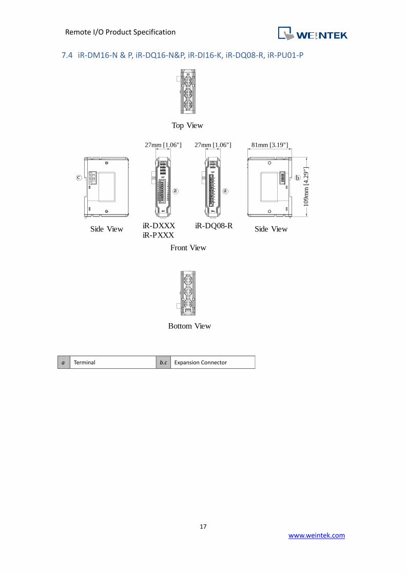
iR-DM16-N & P, iR-DQ16-N&P, iR-DI16-K, iR-DQ08-R, iR-PU01-P 7.4
a Terminal b.c Expansion Connector
英文版 簡中版 日文版
81mm [3.19"]
10
9m
m [
4.2
9"]
27mm [1.06"]
Top View
Side ViewSide View
Bottom View
a
bc
81mm [3.19"]
10
9m
m [
4.2
9"]
bc
81mm [3.19"]
10
9m
m [
4.2
9"]
bc
27mm [1.06"]
Front View
a
iR-DQ08-RiR-DXXX
iR-PXXX
27mm [1.06"]
a
27mm [1.06"]
a
iR-DQ08-RiR-DXXX
iR-PXXX
27mm [1.06"]
a
27mm [1.06"]
a
iR-DQ08-RiR-DXXX
iR-PXXX

Remote I/O Product Specification
18
www.weintek.com
iR-AI04-VI, iR-AM06-VI, iR-AQ04-VI, iR-AI04-TR 7.5
a Terminal b.c Expansion Connector
81mm [3.19"]
10
9m
m [
4.2
9"]
27mm [1.06"]
Top View
Side ViewiR-AXXXSide View
Bottom View
a
bc
27mm [1.06"]
iR-AQ04-VI
a
Remote I/O Product Specification
19
www.weintek.com
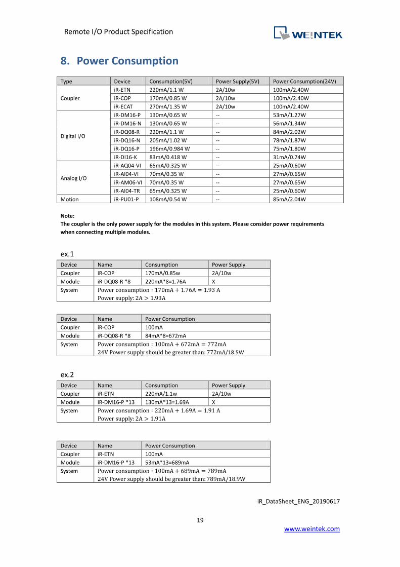
8. Power Consumption
Type Device Consumption(5V) Power Supply(5V) Power Consumption(24V)
Coupler
iR-ETN 220mA/1.1 W 2A/10w 100mA/2.40W
iR-COP 170mA/0.85 W 2A/10w 100mA/2.40W
iR-ECAT 270mA/1.35 W 2A/10w 100mA/2.40W
Digital I/O
iR-DM16-P 130mA/0.65 W -- 53mA/1.27W
iR-DM16-N 130mA/0.65 W -- 56mA/1.34W
iR-DQ08-R 220mA/1.1 W -- 84mA/2.02W
iR-DQ16-N 205mA/1.02 W -- 78mA/1.87W
iR-DQ16-P 196mA/0.984 W -- 75mA/1.80W
iR-DI16-K 83mA/0.418 W -- 31mA/0.74W
Analog I/O
iR-AQ04-VI 65mA/0.325 W -- 25mA/0.60W
iR-AI04-VI 70mA/0.35 W -- 27mA/0.65W
iR-AM06-VI 70mA/0.35 W -- 27mA/0.65W
iR-AI04-TR 65mA/0.325 W -- 25mA/0.60W
Motion iR-PU01-P 108mA/0.54 W -- 85mA/2.04W
Note:
The coupler is the only power supply for the modules in this system. Please consider power requirements
when connecting multiple modules.
ex.1 Device Name Consumption Power Supply
Coupler iR-COP 170mA/0.85w 2A/10w
Module iR-DQ08-R *8 220mA*8=1.76A X
System Power consumption ∶ 170mA + 1.76A = 1.93 A
Power supply: 2A > 1.93A
Device Name Power Consumption
Coupler iR-COP 100mA
Module iR-DQ08-R *8 84mA*8=672mA
System Power consumption ∶ 100mA + 672mA = 772mA
24V Power supply should be greater than: 772mA/18.5W
ex.2 Device Name Consumption Power Supply
Coupler iR-ETN 220mA/1.1w 2A/10w
Module iR-DM16-P *13 130mA*13=1.69A X
System Power consumption ∶ 220mA + 1.69A = 1.91 A
Power supply: 2A > 1.91A
Device Name Power Consumption
Coupler iR-ETN 100mA
Module iR-DM16-P *13 53mA*13=689mA
System Power consumption ∶ 100mA + 689mA = 789mA
24V Power supply should be greater than: 789mA/18.9W
iR_DataSheet_ENG_20190617