reliability improvement of measuring instruments using halt€¦ · high reliability and describes...
TRANSCRIPT

Reliability Improvement of Measuring Instruments using HALT
Jun Kinase, Toshiyuki Ozaki, Hiroaki Okajima
[Summary] Anritsu has introduced the Highly Accelerated Life Test (HALT) to improve the reliability of elec-
tronic measuring instruments. HALT finds potential weaknesses quickly by applying high level
stress to the Device Under Test (DUT). It can determine design-margin operating and destruct
limits. Furthermore, it improves product reliability and stable manufacturing by expanding mar-
gins and reducing costs. This article describes the introduction of HALT by Anritsu, some HALT
examples and improvements, and the validity of HALT.
(1)
1 Introduction
Electronic measuring instruments are traditionally seen
as precision equipment requiring gentle handling in a rela-
tively protected environment. However, test instruments
used on electronic equipment production lines must have
high reliability supporting 24-hour continuous operation
without breakdown because a faulty test instrument im-
pacts line downtime directly.
Recent economic growth in the newly industrializing
economies (NIEs) has driven the movement of production
lines for electronics to the NIEs and there is an urgent need
for test equipment with high reliability even under severe
environmental conditions.
Anritsu introduced the Highly Accelerated Life Test
(HALT) to assure its ability to build high-reliability meas-
uring instruments meeting these market demands.
This article explains how Anritsu uses HALT to assure
high reliability and describes some actual usage examples.
2 Outline of HALT
HALT is a form of destructive testing that applies
stresses exceeding the guaranteed environmental perfor-
mance from the operating limits to the destruct limits to
confirm design margins in an accelerated time period.
By testing from the operation to destruct limits, it is possi-
ble to uncover latent weaknesses in products that can then
be strengthened to improve product reliability.
As shown in Figure 1, the test procedure applies cooling,
heating, rapid thermal transitions, vibration, and combined
environment stresses to the DUT in a series of five phases
to stress the DUT up to its operating limits in each phase.
When some abnormality is confirmed during testing, the
causal fault location is specified, improvements and
strengthening are made and then the test is applied again
with higher stresses.
By using this procedure, HALT does not perform Pass/Fail
testing against fixed reference values, but helps strengthen
product weakness through repeated test/analysis/repair/test
iterations to improve product quality by widening the product
operation and fault margins. Figure 2 shows an image of the
widened operation and fault margins using HALT.
The HALT concept first appeared in the USA in the 1980s
as a method for improving the quality of military hardware.
It spread subsequently to aviation and automotive indus-
tries centered in both Europe and N. America. HALT was
late in reaching Japan with the first applications to improve
the quality of electronics and industrial products appearing
around 2000.
Figure 1 HALT Procedure
67

Anritsu Technical Review No.21 October 2013 Reliability Improvement of Measuring Instruments using HALT
(2)
Figure 2 HALTS Terms and Concepts
3 Anritsu HALT Introduction
Anritsu first introduced HALT at its US R&D section in
2001, followed by a trial period between 2005 and 2007 at
external test sites and then full-scale introduction in the
R&D section of the Atsugi plant.
The in-house HALT facility locations were determined
based on meeting the following conditions.
(1) Installation Location:
Since HALT must support real-time monitoring
and analysis of fault conditions during testing, engi-
neers with a good knowledge of the DUT’s internal
structure must participate in the tests. Consequently,
the HALT facility is located in the same building as
the R&D section.
(2) HALT Chamber:
The size of the chamber was selected to provide
room to spare for testing standalone desktop instru-
ments.
The installed HALT chamber is a Typhoon 2.5
model with the following main specifications manu-
factured by QUALMARK Corporation of the USA.
• Table Size: 762 mm × 762 mm
• Vibration Stress
Max. Acceleration: 50G rms (10 Hz to 5 kHz)
Max. Deployed Mass: 145 kg
Vibration Method: Wide Band, 6-axes Random
• Temperature Stress: –100°C to +200°C
Temp. Ramp Rate: 70°C/minute
Heating Method: Ni-Cr Heater
Cooling Method: Liquid N2 Jet
Figure 3 shows the external view of the installed
HALT chamber.
Figure 3 External View of HALT chamber
(3) Safety Considerations:
The HALT chamber uses large volumes of liquid N2
for cooling and purging to prevent condensation.
When liquid N2 becomes a gas at room temperature,
its volume expands to about 700 times. Since liquid
N2 leaks can purge oxygen from an enclosed space
and create a risk of hypoxia for anyone nearby, both a
low-oxygen warning system and linked ventilation
system are essential from the safety viewpoint.
4 HALT Procedure
4.1 Preparation
The key points in implementing HALT tests are scrupu-
lous monitoring of the DUT operating conditions during
testing and specification of any fault locations based on the
monitoring results.
Most of the internal parts of an electronic measuring in-
strument are mounted on PC boards and the parts count
can range from several thousands to many tens of thou-
sands. Even when an abnormality is discovered by random
testing, if the location of the causal fault cannot be specified,
simply evaluating margin values will not lead to improve
reliability.
To locate fault locations quickly, it is important to prepare
well by having a thorough understanding of the DUT oper-
ating principles and circuits so that the optimum monitor-
ing procedures can be followed.
The following list describes some examples of HALT
preparations.
68

Anritsu Technical Review No.21 October 2013 Reliability Improvement of Measuring Instruments using HALT
(3)
(1) Using FMEA
When using instruments constructed from multiple
circuit blocks, it is very important to have a thorough
prior understanding of what types of faults can occur
in which blocks. The Failure Mode and Effect Analy-
sis (FMEA) method can be very effective for this
purpose. In other words, knowing possible faults for
each block and the relationship with abnormalities
occurring in the DUT can assist early discovery of the
causal fault location. Furthermore, specifying fault
locations can help optimize monitoring locations and
check items in each test phase.
(2) Monitoring Internal Signals
When an instrument is constructed to pass signals
via several circuit modules, the wiring between mod-
ules must be extended beyond the HALT chamber to
easily pinpoint circuit modules causing abnormalities.
In particular, even when externally monitoring
characteristics to check an instrument, sometimes
with feedback circuits where operation abnormalities
cannot be monitored, monitoring the conditions in the
feedback loop can help confirm changes and repro-
ducibility in key device characteristics.
Figure 4 shows the Phase Locked Loop (PLL) of a
synthesizer circuit as a typical feedback type circuit.
Simply monitoring the output signal cannot find cir-
cuit abnormalities because the PLL synthesizer
maintains the frequency lock automatically using a
loop even when the characteristics of the voltage
controlled oscillator (VCO) forming a key part of the
circuit change. As a result, changes in the VCO
characteristics can be confirmed by monitoring the
VCO tuning voltage.
Figure 4 PLL Circuit Monitoring Example
Figure 5 shows an example of the monitoring wir-
ing run from the DUT in the HALT.
(3) Confirming Operating Section Operability
To prevent condensation in the HALT chamber as a
result of the rapid temperature changes, the chamber
is flooded with N2 gas. Consequently, the construction
must form a gastight seal, meaning an operator
cannot touch the DUT during testing.
Figure 5 DUT Monitoring Example
As a result, confirmation of operation functions
such as panel keys requires a remote operation as-
sembly. To resist the vibration stresses and extreme
temperatures in the HALT chamber like the DUT,
this assembly must also have a simple and strong
structure. Figure 6 shows a concrete example of re-
mote panel operation using a wire.
Figure 6 Panel Key Operation Equipment
(4) Considering Devices Without Tolerance to HALT
Unit parts such as commercially available power
supply and CPU Boards also have operational limits
detected by extreme stresses. When the DUT contains
these types of items, it may be necessary to stop opera-
tion of protective circuits so as to prevent test obstacles.
Additionally, already known parts that may fail
69

Anritsu Technical Review No.21 October 2013 Reliability Improvement of Measuring Instruments using HALT
(4)
under extreme testing, such as hard disks and LCDs,
etc., may require removal from the stress factors, by
connecting them outside the HALT chamber, etc.
4.2 HALT Operation and Fault Location
As described in section 1, HALT performs a dozens of se-
ries of related tests to confirm the operation of the DUT.
Some parts of the procedure for confirming the conditions of
as many circuit blocks as possible are automated.
If an abnormality is confirmed from the test results, the op-
eration settings are changed and detailed monitoring is per-
formed to pinpoint the exact location of the operation fault.
Additionally, the temperature and vibration stressors may be
reduced to check whether or not normal operation is recovered.
4.3 Improvement Evaluation Based on HALT Results
It may not be necessary to improve every abnormality
found by HALT. The necessity for improvement has to be
evaluated based on factors, such as the usage environment.
Some bases creteria are explained below:
(1) Items requiring improvement:
• Items where the characteristics change irreversibly
under stress and where the amount of change has
no margin relative to the design specifications.
• Items with no margin relative to the product spec-
ification range when stressed to the abnormal con-
ditions and where abnormality may occur even
under normal operating conditions due to random
dispersion in parts quality, etc.
(2) Items not requiring improvement:
• Items with sufficient margin relative to product
specifications when an abnormality occurs and
when normal operation is recovered when the
stressor is removed even the functions and perfor-
mance are damaged by temporarily imposed stress.
• Items with predefined stress tolerances that have pro-
tection mechanisms or usage warnings for operators.
5 Weaknesses Found by HALT and Improvements
The following types of phenomena can be expected at each
HALT test phase.
• Lo and Hi Temperature Stresses: Drift in device charac-
teristics and abnormal operation
• Rapid Thermal Transition Stress: Physical damage due to
thermal expansion and contraction
• Vibration Stress: Parts detachment, damage, solder
breaks, connector and relay contact failures
Some concrete of weaknesses that have been discovered
using HALT and the improvements are outlined in the fol-
lowing section.
(1) Change in Characteristics of Time Constant Circuit
Under low temperature stress of –30°C, an alumi-
num electrolytic capacitor used in a monostable mul-
tivibrator IC time constant circuit (Figure 7) showed
an increase in the ESR value. As a result, at the
monostable multivibrator IC reset, the capacitor
discharge was inadequate and no pulse was output.
The aluminum electrolytic capacitor was replaced by
a polymer organic semiconductor type with low ESR
temperature dependency.
Figure 7 Monostable Multivibrator IC
(2) Loss of Frequency Lock in PLL Synthesizer Circuit
Under low temperature stress of –55°C, the 100
MHz PLL synthesizer circuit lost the frequency lock
(Figure 8). The 100 MHz quartz resonator used in the
reference signal generator of this synthesizer suf-
fered frequency drift causing the PLL to go out of
range. However, since the part had sufficient margin
for the normal operating environment when the os-
cillation frequency returned to normal, there was no
need to take corrective actions.
Figure 8 Unlocked Signal Drift (Span = 5 kHz)
(3) Misoperation Due to Swelling of Acryl Panel Keys
Under low temperature stress of –60°C,the acryl
70

Anritsu Technical Review No.21 October 2013 Reliability Improvement of Measuring Instruments using HALT
(5)
front panel contracted and the panel keys failed to
make contact. Since this problem did not occur under
normal usage and storage conditions, it was evalu-
ated as not requiring corrective action.
(4) Logic Circuit Design Error
Under low temperature stress of –20°C,the logic
circuit did not operate against to the design. Applying
5 V at the logic signal input of the 3.3 V FPGA caused
misoperation. The FPGA logic input circuit has a
body diode between it and the power supply. In nor-
mal operation, current does not flow through this
body diode but inputting a voltage exceeding the
power supply voltage caused damage allowing cur-
rent to flow, and an increase in the leak current
(Figure 9). This circuit mis-design was not discovered
because mis-operation did not occur because the leak
current was extremely small in the nominal product
operation temperature range. However, the increased
leak current caused by the HALT temperature stress
forced the condition to a constant High level. Since
this circuit error was discovered at the design stage,
it could be remedied at an early stage.
Figure 9 FPGA Input Circuit
(5) Detached Electrolytic Capacitor
Under vibration stress, an aluminum surface
mounted electrolytic capacitor became detached from
the PC board. The case was not a solder break but
was actually breaks at the part leads (Figure 10).
This problem happens in all DUTs, but since dam-
aging-vibration stress levels do not occur in the
normal usage environment, corrective actions were
not deemed necessary. However, because the part
detachment caused failure in the HALT tests, we re-
inforced the part mounting with an adhesive.
Figure 10 Detached Aluminum Electrolytic Capacitor
(6) Cracked Backup Battery Lead
Under vibration stress of 45G rms, the leads of the
backup primary battery mounted on the PC board
cracked (Figure 11). Although similar to the previously
described broken leads of the aluminum electrolytic
capacitor, a cracked battery lead runs a risk of internal
short circuit, so the battery mounting was strengthened
with an adhesive, especially in handheld-type devices.
Figure 11 Fractured Backup Battery Lead
(7) Disconnected CF Memory card
Under vibration stress of 25G rms, the compact
flash (CF) memory card used for saving data inter-
nally slipped out of its connector to lose contact
(Figure 12). The CF card connector had a short mat-
ing fit causing lost contact when the card moved
slightly so the corrective action was apllied to an-
other CF card used products.
Figure 12 CF Card Slipping from Connector
71
Anritsu Technical Review No.21 October 2013 Reliability Improvement of Measuring Instruments using HALT
(6)
(8) Damaged Crystal Resonator
Under vibration stress of 50G rms, the equipment
measurement drifted. The cause was found to be dam-
age to the crystal resonator holder of the oven-controlled
crystal oscillator (OCXO) used as the reference fre-
quency source (Figure 13). This OCXO is used in many
products but since there have been no reports of this
type of fault, corrective actions were not taken and this
was only recorded as a weakness of this part.
Figure 13 Damaged Crystal Resonator
(9) Faulty Serial-ATA Connector
Under vibration stress of 20G rms, the serial-ATA
connector to the hard disk drive suffered disconnec-
tion and loss of function. Since this was a problem
with the connector form and materials, it was solved
by changing to a different part maker.
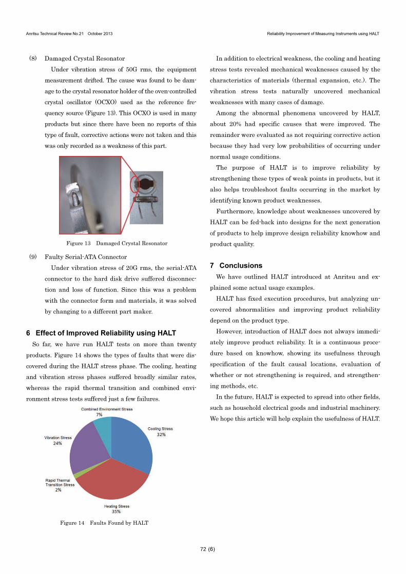
6 Effect of Improved Reliability using HALT
So far, we have run HALT tests on more than twenty
products. Figure 14 shows the types of faults that were dis-
covered during the HALT stress phase. The cooling, heating
and vibration stress phases suffered broadly similar rates,
whereas the rapid thermal transition and combined envi-
ronment stress tests suffered just a few failures.
Figure 14 Faults Found by HALT
In addition to electrical weakness, the cooling and heating
stress tests revealed mechanical weaknesses caused by the
characteristics of materials (thermal expansion, etc.). The
vibration stress tests naturally uncovered mechanical
weaknesses with many cases of damage.
Among the abnormal phenomena uncovered by HALT,
about 20% had specific causes that were improved. The
remainder were evaluated as not requiring corrective action
because they had very low probabilities of occurring under
normal usage conditions.
The purpose of HALT is to improve reliability by
strengthening these types of weak points in products, but it
also helps troubleshoot faults occurring in the market by
identifying known product weaknesses.
Furthermore, knowledge about weaknesses uncovered by
HALT can be fed-back into designs for the next generation
of products to help improve design reliability knowhow and
product quality.
7 Conclusions
We have outlined HALT introduced at Anritsu and ex-
plained some actual usage examples.
HALT has fixed execution procedures, but analyzing un-
covered abnormalities and improving product reliability
depend on the product type.
However, introduction of HALT does not always immedi-
ately improve product reliability. It is a continuous proce-
dure based on knowhow, showing its usefulness through
specification of the fault causal locations, evaluation of
whether or not strengthening is required, and strengthen-
ing methods, etc.
In the future, HALT is expected to spread into other fields,
such as household electrical goods and industrial machinery.
We hope this article will help explain the usefulness of HALT.
72

Anritsu Technical Review No.21 October 2013 Reliability Improvement of Measuring Instruments using HALT
(7)
References
1) G. K Hobbs: Accelerated Reliability Engineering, Halt and
Hass
2) M. Kimura: “機器は壊して強くする 新試験手法 HALT が離陸”,
Nikkei Electronics, December 1, 2008
3) M. Kimura: “壊して作る HALT 活用設計 コスト競争力の源泉に”,
Nikkei Electronics, October 17, 2011
Authors
Jun Kinase
Technical Support Term
Manufacturing Engineering Dept.
SCM dev.
Measurement Business Group
Toshiyuki Ozaki
Technical Support Term
Manufacturing Engineering Dept.
SCM dev.
Measurement Business Group
Hiroaki Okajima
EMC Center
Anritsu Customer Services Co., Ltd.
Publicly available
73