release 2.1 - april 2017
TRANSCRIPT

Alcatel-Lucent OXO Connect
Installation ManualRelease 2.1 - April 2017
3EH21123USAA Ed. 01

Legal noticeThe information presented is subject to change without notice.
ALE International assumes no responsibility for inaccuracies contained herein.
Copyright © ALE International, 2017
DisclaimerWhile efforts were made to verify the completeness and accuracy of the information contained in thisdocumentation, this document is provided “as is”. To get more accurate content concerning CrossCompatibilities, Product Limits, Software Policy and Feature Lists, please refer to the accuratedocuments published on the Business Partner Web Site.
In the interest of continued product development, ALE International reserves the right to makeimprovements to this documentation and the products it describes at any time, without notice orobligation.
The CE mark indicates that this product conforms to the following Council Directives:
• 2014/53/EU for radio equipment• 2014/35/EU and 2014/30/EU for non radio equipment (including wired Telecom Terminal
Equipment)• 2014/34/EU for ATEX equipment• 2011/65/EU (RoHS)

Chapter 1General Presentation
1.1 Preliminary....................................................................................................................................... 101.1.1 Document summary...........................................................................................................................101.1.2 Symbols used IN the documentation ....................................................................................... 101.1.3 Clauses.................................................................................................................................................... 10
1.2 Protection against Interferences................................................................................10
1.3 Security................................................................................................................................................111.3.1 Safety rules............................................................................................................................................ 111.3.2 Safety symbols/logos description................................................................................................15
Chapter 2Hardware: Platform and Interfaces
2.1 Overview.............................................................................................................................................18
2.2 Platforms............................................................................................................................................182.2.1 OXO Connect Compact................................................................................................................... 192.2.2 OXO Connect S................................................................................................................................... 202.2.3 OXO Connect M.................................................................................................................................. 212.2.4 OXO Connect L....................................................................................................................................21
2.3 Installation Summary.............................................................................................................23
2.4 Equipment.........................................................................................................................................242.4.1 Boards and Options........................................................................................................................... 242.4.2 Detailed description........................................................................................................................... 25
Table ofcontents Installation Manual
3EH21123USAA - Ed. 01 - April 2017 - Installation Manual 3/207

Chapter 3System Services
3.1 Software Licence Management....................................................................................333.1.1 Software licence management.....................................................................................................33
3.2 Software Keys...............................................................................................................................333.2.1 Voice Services Available in "Limited" Mode...........................................................................343.2.2 Software Key Change.......................................................................................................................34
3.3 Cloud Connect Operation (CCO)................................................................................ 353.3.1 Cloud Connect Operation overview........................................................................................... 353.3.2 Registration of the product............................................................................................................. 363.3.3 Configuring CCO on OXO Connect........................................................................................... 363.3.4 Maintenance.......................................................................................................................................... 36
3.4 CCO VPN service....................................................................................................................... 373.4.1 CCO VPN service Architecture.................................................................................................... 373.4.2 VPN link setup description..............................................................................................................39
3.5 Rainbow.............................................................................................................................................. 423.5.1 Rainbow overview...............................................................................................................................423.5.2 Rainbow deployment.........................................................................................................................42
Chapter 4Installation and Cabling
4.1 Presentation....................................................................................................................................454.1.1 Location of Unit.................................................................................................................................... 454.1.2 Environment...........................................................................................................................................46
4.2 Connections and Cabling.................................................................................................. 474.2.1 Output Connectors............................................................................................................................. 474.2.2 Types of Cable to Use .....................................................................................................................494.2.3 Connection of PowerCPU EE Board ........................................................................................504.2.4 Connecting Terminals ...................................................................................................................... 50
Table ofcontents Installation Manual
3EH21123USAA - Ed. 01 - April 2017 - Installation Manual 4/207

4.2.5 Connection to the Public Network...............................................................................................524.2.6 LAN Connection ................................................................................................................................. 544.2.7 Connecting Auxiliary Equipment ................................................................................................ 55
4.3 Power Supply.................................................................................................................................584.3.1 Connecting an External EPS48 Power Supply.................................................................... 584.3.2 Battery Implementation.................................................................................................................... 584.3.3 Connecting an External Battery Unit......................................................................................... 594.3.4 Connecting a UPS.............................................................................................................................. 714.3.5 Mains Connection - Ground Connection................................................................................. 724.3.6 Power Up................................................................................................................................................ 73
4.4 SIP Terminals.................................................................................................................................734.4.1 8001/8001G Deskphone..................................................................................................................734.4.2 8082 My IC Phone..............................................................................................................................764.4.3 4135 IP Conference Phone............................................................................................................874.4.4 Generic SIP Phones.......................................................................................................................... 93
4.5 8018 DeskPhone......................................................................................................................... 964.5.1 Commissioning.....................................................................................................................................96
4.6 8028/8038/8068 Premium DeskPhones................................................................ 974.6.1 Commissioning.....................................................................................................................................97
4.7 Alcatel-Lucent IP Touch 4018 phone Extended Edition.....................1014.7.1 Commissioning...................................................................................................................................101
4.8 8029/8039 Premium DeskPhones............................................................................ 1054.8.1 Commissioning...................................................................................................................................105
4.9 4019 Digital Phone..................................................................................................................1064.9.1 Commissioning...................................................................................................................................106
4.10 V24/CTI Interface Module.................................................................................................1084.10.1 Hardware description...................................................................................................................... 1084.10.2 Hardware configuration..................................................................................................................1094.10.3 External connections....................................................................................................................... 110
4.11 AP Interface Module..............................................................................................................1124.11.1 Hardware description...................................................................................................................... 1124.11.2 Hardware configuration.................................................................................................................. 1134.11.3 External connections....................................................................................................................... 115
4.12 S0 Interface Module...............................................................................................................117
Table ofcontents Installation Manual
3EH21123USAA - Ed. 01 - April 2017 - Installation Manual 5/207
4.12.1 Hardware description...................................................................................................................... 1174.12.2 Hardware configuration.................................................................................................................. 1194.12.3 External connections.......................................................................................................................120
4.13 Intelligent Base Stations...................................................................................................1234.13.1 Detailed description......................................................................................................................... 1234.13.2 Safety rules.......................................................................................................................................... 131
4.14 IP-DECT Base Stations.......................................................................................................1344.14.1 Detailed description......................................................................................................................... 134
4.15 PIMphony.........................................................................................................................................1364.15.1 Overview................................................................................................................................................1364.15.2 Additional Information..................................................................................................................... 136
4.16 PIMphony Touch.......................................................................................................................1384.16.1 Overview................................................................................................................................................1384.16.2 Architecture..........................................................................................................................................139
4.17 Extending Your Installation........................................................................................... 1414.17.1 Configuration of Stations...............................................................................................................1414.17.2 Adding/Replacing Boards............................................................................................................. 1434.17.3 Adding a Module Expansion........................................................................................................1434.17.4 Installation Upgrade.........................................................................................................................144
4.18 My IC Plugin for Outlook®.............................................................................................. 1464.18.1 Detailed description......................................................................................................................... 146
4.19 ACD applications..................................................................................................................... 1544.19.1 Platforms supported by ACD applications............................................................................ 1544.19.2 Installation.............................................................................................................................................155
Chapter 5Station Default configuration
5.1 Default configuration........................................................................................................... 1565.1.1 8038 Premium DeskPhone, 8039 Premium DeskPhone and 8068 Premium
DeskPhone sets.................................................................................................................................1565.1.2 8028 Premium DeskPhone, 8029 Premium DeskPhone sets.................................... 167
Table ofcontents Installation Manual
3EH21123USAA - Ed. 01 - April 2017 - Installation Manual 6/207

5.1.3 Alcatel-Lucent IP Touch 4018 Phone set.............................................................................. 1685.1.4 Other predefined data.....................................................................................................................168
Chapter 6Start-Up
6.1 System startup from a phone set............................................................................ 1696.1.1 General dynamic keys.................................................................................................................... 1696.1.2 System type......................................................................................................................................... 1706.1.3 Installation number...........................................................................................................................1706.1.4 IP configuration.................................................................................................................................. 1716.1.5 Numbering plan..................................................................................................................................1756.1.6 Terminal DDI numbers....................................................................................................................1756.1.7 Number of lines connected to the public network............................................................. 1776.1.8 Operation of terminals and operator terminal..................................................................... 1786.1.9 Attributing mailboxes.......................................................................................................................1786.1.10 ARI number..........................................................................................................................................1796.1.11 Authentication..................................................................................................................................... 1796.1.12 User information language........................................................................................................... 1806.1.13 Basic metering unit cost.................................................................................................................1806.1.14 TIME & DATE......................................................................................................................................1806.1.15 SYSTEM RESET.............................................................................................................................. 181
6.2 System Startup from OMC..............................................................................................1816.2.1 Overview................................................................................................................................................1816.2.2 Installation procedure......................................................................................................................1816.2.3 Accessing the System.................................................................................................................... 1826.2.4 Downloading the Software............................................................................................................1896.2.5 Services provided............................................................................................................................. 191
Table ofcontents Installation Manual
3EH21123USAA - Ed. 01 - April 2017 - Installation Manual 7/207

Chapter 7Maintenance Level 1
7.1 Battery Maintenance.............................................................................................................1957.1.1 Internal Battery Characteristics..................................................................................................1957.1.2 External Battery Characteristics................................................................................................ 195
7.2 Board Battery Maintenance........................................................................................... 196
7.3 Maintenance of Ventilation System ......................................................................196
7.4 Replacing the CPU Board................................................................................................196
7.5 Replacing the Chassis........................................................................................................196
7.6 Adding and Replacing Interface Boards...........................................................1967.6.1 Adding a board into a vacant slot..............................................................................................1977.6.2 Replacing an existing board........................................................................................................ 198
7.7 MSDB replacement.................................................................................................................198
7.8 RAM replacement.................................................................................................................... 198
Chapter 8Glossary
8.1 A............................................................................................................................................................... 199
8.2 B............................................................................................................................................................... 199
8.3 C............................................................................................................................................................... 200
8.4 D............................................................................................................................................................... 200
8.5 E................................................................................................................................................................201
8.6 F................................................................................................................................................................ 201
8.7 G............................................................................................................................................................... 201
8.8 H............................................................................................................................................................... 202
Table ofcontents Installation Manual
3EH21123USAA - Ed. 01 - April 2017 - Installation Manual 8/207

8.9 I..................................................................................................................................................................202
8.10 K............................................................................................................................................................... 203
8.11 L................................................................................................................................................................ 203
8.12 M...............................................................................................................................................................203
8.13 N............................................................................................................................................................... 203
8.14 O............................................................................................................................................................... 204
8.15 P................................................................................................................................................................204
8.16 Q............................................................................................................................................................... 205
8.17 R............................................................................................................................................................... 205
8.18 S................................................................................................................................................................205
8.19 T................................................................................................................................................................ 206
8.20 U............................................................................................................................................................... 206
8.21 V................................................................................................................................................................207
8.22 W.............................................................................................................................................................. 207
Table ofcontents Installation Manual
3EH21123USAA - Ed. 01 - April 2017 - Installation Manual 9/207

Chapter
1 General Presentation
1.1 Preliminary
1.1.1 Document summaryThis document contains installation and cabling procedures of racks, boards, phone sets and interfacemodules. It also explains startup procedures for OXO Connect and phone sets, along with safetyinformation and conformance with directives, and basic maintenance operations.
This document only describes the features supported by OXO Connect RC2.0* (for example: MMCstation is not described since it is not supported). Please refer to the OXO Connect DocumentationNote, for historical information. In addition, the Cross Compatibility document is the reference fordetailed status about supported and unsupported devices and applications.
* RC2.0 stands for any release starting from 2016 introducing Connect capabilities.
It appears on:
• Product stickers with release format: RC020/xx.yy• In any documentation (including this one) as: R2.0
1.1.2 Symbols used IN the documentation
See note.
See important information.
1.1.3 ClausesCopyright and Trademarks
Datalight is a registered trademark of Datalight,Inc.
FlashFXtm is a trademark of Datalight, Inc.
Outlook is either a registered trademark, or a trademark of Microsoft Corporation in the United Statesand/or other countries
Copyright 2001 - 2016 Datalight, Inc., All Rights Reserved.
1.2 Protection against InterferencesNotice to the attention of the users and installer:
USA - FCC (Federal Communication Commission)
This equipment has been tested and found to comply with the limits for a Class B digital device,pursuant to part 15 of the FCC Rules. These limits are designed to provide reasonable protectionagainst harmful interference in a residential installation. This equipment generates, uses and canradiate radio frequency energy and, if not installed and used in accordance with the instructions, maycause harmful interference to radio communications. However, there is no guarantee that interferencewill not occur in a particular installation. If this equipment does cause harmful interference to radio or
3EH21123USAA - Ed. 01 - April 2017 - Installation Manual 10/207

television reception, which can be determined by turning the equipment off and on, the user isencouraged to consult the installer or service person.
Changes or modifications to this equipment, not expressly approved by ALE International, may causeharmful interference and void the user’s authority to operate this equipment.
Japan - VCCI (Voluntary Control Council for Interference)
Translation :
This is a Class B product based on the standard of the Voluntary Control Council for Interference fromInformation Technology Equipment (VCCI). If this is used near a radio or television receiver in adomestic environment, it may cause radio interference. Install and use the equipment according to theinstruction manual.
1.3 Security
1.3.1 Safety rules
1.3.1.1 Safety declaration
We, ALE International 32, avenue Kléber 92700 Colombes - France, declare that the productspresented in this manual are in compliance with the essential requirements of European directives2014/30/EU (EMC), 2014/35/EU (LVD), 2014/53/EU (RED), 2009/125/EC (ErP) and 2011/65/UE(RoHS).
Any unauthorized modification to the products invalidates this declaration of conformance.
In pursuance of this directive which appeared in the Official Journal of the European Community onApril 7 1999, this equipment can be used in all European Community member states and countries thataccept CE Mark.
Copyright 2001 - 2016 Datalight, Inc., All Rights Reserved. In order to better serve its customers, ALEInternational reserves the right to modify the characteristics of its products without notice.
ALE International - 32, avenue Kléber F-92700 Colombes RCS Paris 602 033 185.
1.3.1.2 General recommendations
Protective earthing
This equipment must imperatively be connected to a permanent earth protection installedaccording to current legislation.
Chapter 1 General Presentation
3EH21123USAA - Ed. 01 - April 2017 - Installation Manual 11/207

Installation of the mains power
The mains power must be installed as close as possible to the unit and must be easily accessible. Thepower supply lead is used as the master switch.
Free board slots
It is essential that empty board slots are guarded with the appropriate expansion slotcovers for full electromagnetic shielding, the safety of people working nearby (in the presenceof hazardous voltages) and the prevention of fire propagation (from inside the unit).
Lead and Lithium batteries
There is a risk of explosion if the batteries are incorrectly replaced. Only use batteries ofidentical type, or manufacturer recommended equivalents. Discard used batteries according tothe battery manufacturer's instructions.
Power supply
Due to the presence of hazardous voltages, the rear metal panel can only be removed byqualified personnel.
If it is necessary to carry out work on a power supply unit, first disconnect the mains cable from thesystem as well as any external EPS48 power connections that may be connected. Then remove therear metal panel of the power supply block and disconnect the batteries.
High leakage current
A permanent earth connection is essential before making TRT/TNV-3 telecommunicationnetwork connections.
In the case of a poor earth connection, it is MANDATORY to disconnect the telecommunicationsaccesses before reconnecting the equipment to earth. It is then necessary to verify that all theconnections have been made correctly.
Before removing any board that provides access to a telecommunications network ofclass TRT/TNV-3, make sure you disconnect the links. Reconnect the links once the board is re-inserted.
Installation of DECT bases
For further information on recommendations relating to the exposure of the public to theelectromagnetic field, refer to "Installation of DECT bases".
Chapter 1 General Presentation
3EH21123USAA - Ed. 01 - April 2017 - Installation Manual 12/207

1.3.1.3 Declaration of conformance with directives1.3.1.3.1 Ukrain
001
This Ukrainian label indicates that this product is compliant with Technical Regulations for LowVoltage Electrical Equipment and Technical Regulations in Electro-Magnetic Compatibility in force inUkraine.
This equipment is designed to be connected to the public telephone network using the appropriateinterfaces.
1.3.1.3.2 EC Logo
The CE labeling indicates that this product conforms to the European directives currently in force, inparticular:
• 2014/35/EU and 2014/30/EU for non radio equipment (including wired Telecom TerminalEquipment)
• 2014/53/EU for radio equipment• 2014/34/EU for ATEX equipment• 2011/65/EU (RoHS)• 2012/19/EU (Waste Electrical & Electronic Equipment)
1.3.1.4 Interface classification1.3.1.4.1 OXO Connect Small, Medium, Large
SELV: Safety Extra Low Voltage TNV-3: Telecommunication Network Voltage
Chapter 1 General Presentation
3EH21123USAA - Ed. 01 - April 2017 - Installation Manual 13/207

PowerCPU EE
PowerCPU EE
PowerCPU EE
Figure 1.1: OXO Connect Small, Medium, Large
Chapter 1 General Presentation
3EH21123USAA - Ed. 01 - April 2017 - Installation Manual 14/207

1.3.1.4.2 OXO Connect Compact
PowerCPU EE
MIX-2MIX-2
MIX-2
Figure 1.2: OXO Connect Compact
Note:The Mini-MIX daughter board requires BACKXS-N back panel and PSXS-N power supply module. The Mini-MIXdaughter board can be used only in an OXO Connect Compact
1.3.2 Safety symbols/logos description• Direct Current (DC) indication
xxV yyA
xxV: Input DCVoltage
yyA: Input Current maximum
• Mains power supply indication
xx – zzV ~ / aa – bbHz / yyA
xx – zzV: Input voltage range
aa – bbHz: Frequency range
yyA: Input Current maximum
• Earth protection logo
Chapter 1 General Presentation
3EH21123USAA - Ed. 01 - April 2017 - Installation Manual 15/207

HIGH LEAKAGE CURRENT
Necessity to connect permanent earth before telecom access because of the highleakage current (>3.5mA).
• Fuse logo
Caution:For continued protection against risk of fire, replace only with same type and rating of fuse.
Example: T 2,5AH / 250V
Type (T): Time Lag type
Current rating: 2,5A
Voltage rating: 250V
• "WARNING" logo
Safety instructions to follow before installation or maintenance of the equipment.
Before installing this equipment you must read the installation documents due to elec-tric shock Hazard.
The rear of panel and the front boards should only be removed by qualified mainte-nance personnel.
Disconnect the mains cord before remaining the rear panel.
• Waste Electrical and Electronic Equipment (WEEE) logo
Chapter 1 General Presentation
3EH21123USAA - Ed. 01 - April 2017 - Installation Manual 16/207

The Waste Electrical and Electronic Equipment (WEEE) logo indicates that the productcomplies with the article 11(2) of European Directive 2012/19/EU .
Chapter 1 General Presentation
3EH21123USAA - Ed. 01 - April 2017 - Installation Manual 17/207

Chapter
2 Hardware: Platform and Interfaces
2.1 OverviewOXO Connect is a business communication server offering proven telephony functions with datamanagement. This "multi-purpose" server provides a turnkey global communication solution for smalland medium-scale businesses with 6 to 300 employees.
The OXO Connect range includes:
• the OXO Connect Compact platform• the OXO Connect Small platform• the OXO Connect Medium platform• the OXO Connect Large platform
The OXO Connect range is supplied:
• with all the sub-assemblies required for your particular configuration,• configured with the software key corresponding to the level of services desired (according to
country).
The stations are packaged separately.
2.2 PlatformsIn order to cover the entire SME/SMI market segment (6 to 300 users), OXO Connect is available in:
• One platform which is fixed either directly to the wall, or to a wall support (US version): the OXOConnect Compact platform (also referred to as OXO Connect Compact)
• Three 19" platforms which can be mounted in a rack or placed on a shelf:
• The OXO Connect Small platform (also referred to as OXO Connect S)• The OXO Connect Medium platform (also referred to as OXO Connect M)• The OXO Connect Large platform (also referred to as OXO Connect L)
3EH21123USAA - Ed. 01 - April 2017 - Installation Manual 18/207

2.2.1 OXO Connect Compact
• 18 ports.• 1 CPU slot + 1 MIX slot• Energy consumption: 1.5 A (240 V)• Dimension: H = 345 mm; W = 370 mm; D = 65 mm.• Weight: 5.1 kg.
The following mixed boards are available:
• MIX 2/4/4-2• MIX 4/4/8-2• MIX 4/8/4-2• AMIX-1 4/4/4• AMIX-1 4/4/8• AMIX-1 4/8/4• Mini-MIX (PowerCPU EE daughter board)
Note:This wall-mounted version is also called XS-N.
The Mini-MIX daughter board, plugged on a PowerCPU EE board, requires an OXO Connect Compact.
The PowerCPU EE board shows a Mini-MIX LED activated when the Mini-MIX daughter board isdetected on the PowerCPU EE board.
Chapter 2 Hardware: Platform and Interfaces
3EH21123USAA - Ed. 01 - April 2017 - Installation Manual 19/207

PowerCPU EE Front Stiffener
Zoom on SLI1/2 & AUX and ISDN T0 RJ45 Connectors / PowerCPU EE
ZA1Ground +12V CenRg A
CenRg BZB1 ZA2 ZB2
1 2 3 4 5 6 7 8
SLI1/2 & AUX RJ45 pin-out
12345678
SLI1/2 &AUX
12345678
RX+TX+ TX-RX-
1 2 3 4 5 6 7 8
ISDN T0 1 & 2 RJ45 pin-outISDN T0
2x T0 connections of Mini-MIX board
2x Z connections of Mini-MIX board
MODULE
Figure 2.1: Mini-MIX connections on PowerCPU EE Board
Equipment numbering:
• Slot 80 EN 01 for the first T0 access (80-001-01)• Slot 80 EN 02 for the second T0 access (80-002-01)• Slot 80 EN 09 for the first Z access (80-009-01)• Slot 80 EN 10 for the second Z access (80-010-01)
2.2.2 OXO Connect S
Chapter 2 Hardware: Platform and Interfaces
3EH21123USAA - Ed. 01 - April 2017 - Installation Manual 20/207
• 32 ports.• 1 CPU slot 2 general-purpose slots (no SLI16-2 board).• Energy consumption: 1 A (230 V) / 2 A (110 V) - 80 W.• Dimension: H = 66 mm; W = 442 mm; D = 400 mm.• Weight: 6 kg.
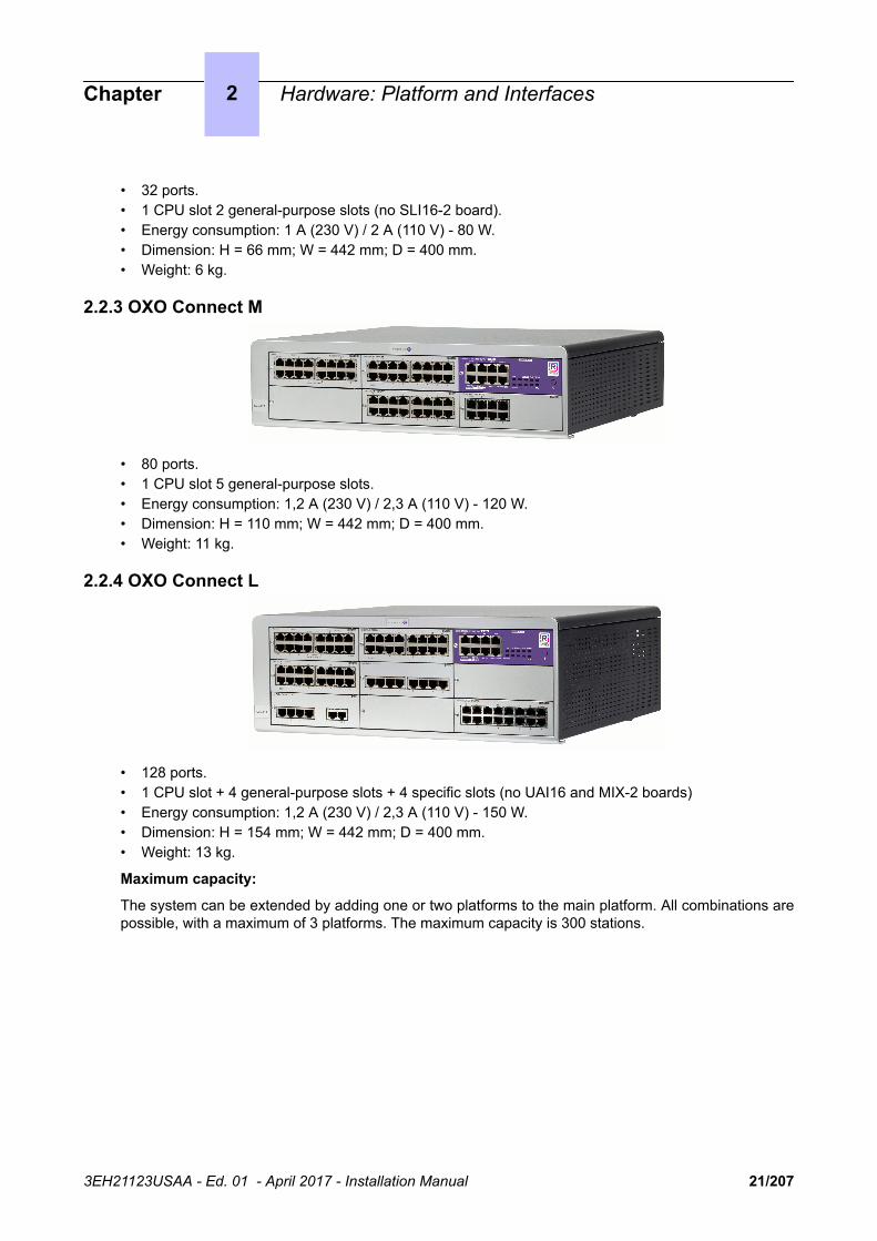
2.2.3 OXO Connect M
• 80 ports.• 1 CPU slot 5 general-purpose slots.• Energy consumption: 1,2 A (230 V) / 2,3 A (110 V) - 120 W.• Dimension: H = 110 mm; W = 442 mm; D = 400 mm.• Weight: 11 kg.
2.2.4 OXO Connect L
• 128 ports.• 1 CPU slot + 4 general-purpose slots + 4 specific slots (no UAI16 and MIX-2 boards)• Energy consumption: 1,2 A (230 V) / 2,3 A (110 V) - 150 W.• Dimension: H = 154 mm; W = 442 mm; D = 400 mm.• Weight: 13 kg.
Maximum capacity:
The system can be extended by adding one or two platforms to the main platform. All combinations arepossible, with a maximum of 3 platforms. The maximum capacity is 300 stations.
Chapter 2 Hardware: Platform and Interfaces
3EH21123USAA - Ed. 01 - April 2017 - Installation Manual 21/207

Chapter 2 Hardware: Platform and Interfaces
3EH21123USAA - Ed. 01 - April 2017 - Installation Manual 22/207

2.3 Installation Summary
Z Board
UA Board
Auxiliary
IBS
Analog set Fax
IBS DECT
T0 – T2Trunk/Tie line
Private Network (QSIG)
ISDN
Wireless network (3G to 3,5G)
PSTN
HSL Link
Core CPU
LANLAN switch
Analog Trunk/DDI
Tie line Private Network
VoIP
To expansion cabinet
Internet
SBC
Internet
MMCRS 232 or LAN
V24(Metering)
or S0
Plugware
Plugware
IP/LAN10/100 base T
IP Plugware
PC
UA
OmniAccess Wireless Switch
IP DeskPhones
IP DAP
IP DECT
OmniTouch VLAN Handsets
Access Point
Switch 32x32
IP-DECT Solution
IBS DECT Solution
Voice MailCSTAACD
Integrated applications
Alarm Audio I/O
PC
Digital Premium Deskphones
OTCV applications
This hardware must be installed on the customer's site, by a qualified installer, in compliancewith the instructions provided with the hardware.
Equipment shall be installed at the factory or in the field by submitter's trained personnel inaccordance with the installation instruction provided with the equipment.
Chapter 2 Hardware: Platform and Interfaces
3EH21123USAA - Ed. 01 - April 2017 - Installation Manual 23/207

2.4 Equipment
2.4.1 Boards and OptionsThe following table lists the boards available on OXO Connect Small, Medium, Large.
For boards not in the catalogue anymore, see the technical communication on hardware and softwarecompatibility.
Board Function Optional boards Connections
APA2
APA4
APA8
2, 4 or 8 analog trunk line inter-faces
GSCLI: Ground Startsignaling
CLIDSP: CLIP localmanagement
Analog trunk line (TL), TL-PS diversion
BRA2-2
BRA4-2
2 or 4 T0 basic accesses ISDN network
ISDN-EFM T0/S0 forward-ing box
PowerCPU EE Processing Unit, MSDB (MassStorage Daughter Board) 8 GBequipped with eMMC (embed-ded Multi-Media Card), 512 MBDDR2 RAM.
HSL1, HSL2: intercon-nection with expansionmodules
AFU, AFU-1: (AuxiliaryFunction Unit)
Mini-MIX providing twoZ (Analog Extension)ports and two T0 (ISDNBasic Rate) accesses
ARMADA VoIP32, AR-MADA VoIP64: VoIPchannels
Lanswitch or Ethernet ter-minal
Please-wait message play-er
Tuner for background mu-sic
Alarm
Doorphone
Loudspeaker
General call ringer
ISDN-EFM T0/S0 forward-ing box
Pulse metering device
OMC
LanX8-2
LanX16-2
8 or 16 port Ethernet 10/100 BT(of which 1 or 2 10/100/1000 BTports on LanX-2 boards)
@ Phones, Hub, Lanswitch,PC, etc.
PowerMEX(equipped withan HSL1board)
Extension module controller
MIX244-2
MIX448-2
MIX484-2
2 or 4 T0 basic accesses + 4 or8 UA interfaces + 4 or 8 Z inter-faces
ISDN network, analog Zterminals and Alcatel-Lu-cent 9 series
Chapter 2 Hardware: Platform and Interfaces
3EH21123USAA - Ed. 01 - April 2017 - Installation Manual 24/207

Board Function Optional boards Connections
AMIX484-1
AMIX448–1
AMIX444–1
4 analog line accesses, 4 or 8UA interfaces and 4 or 8 Z inter-faces
GSCLI: Ground Startsignaling
CLIDSP: local CLIPmanagement
METCLI
PSTN network, analog Zterminals and Alcatel-Lu-cent 9 series
PRA-T2
PRA-T1
DLT2
T1-CSS
PCM R2
PRA -T2, DLT2: 30 x 64-KpbsB-channels + 1 x 64-Kbps D-channel; 2048 Kbps.
PRA-T1: 23 x 64-Kbps B-chan-nels + 1 x 64-Kbps D-channel;1544 Kbps
23 x 64-Kbps B-channels + 1 x64-Kbps D-channel
PCM R2: 30 x 64 Kbps B-chan-nels +1 x 4 Kbps signaling chan-nel; 2048 Kbps.
PRA-T2: ISDN network
DLT2: Private QSIG net-work
PRA-T1: Hong-Kong ISDNnetwork
PCM R2: Public network
SLI4-2
SLI8-2
SLI16-2
4, 8 or 16 Z interfaces Analog Z terminals
UAI4
UAI8
UAI16
UAI16-1
4, 8 or 16 UA interfaces
UAI16-1 board: possibility ofpowering terminals connected tothe 16 interfaces remotely froman external EPS48 power sup-ply
Alcatel-Lucent 9 series
4070 IO/EO DECT basestations
EPS48 only on interface 1of the UAI16-1 board
2.4.2 Detailed description
2.4.2.1 Processing Unit PowerCPU EE Board
The PowerCPU EE board performs the CPU functions of an OXO Connect system.
Chapter 2 Hardware: Platform and Interfaces
3EH21123USAA - Ed. 01 - April 2017 - Installation Manual 25/207

2.4.2.1.1 Function of the LEDs
Name Color Function
CPU Green CPU functioning LED (flashing)
POWER Red/Green • Mains operation: steady green LED• Battery operation: steady yellow LED• Idle: flashing red LED• System shut down: steady red LED
FAN Red/Green • Both fans functioning: steady green LED• 1 or both fans down: steady red LED
LAN Green LAN functioning LED (flashes when there is traffic)
Mini-MIX Green (only on OXOConnect Compact plat-form)
Green only when accepted by the license 2B channels forMIX-2 boards. Detection of Mini-MIX board in OXO ConnectCompact platform.
MODULE Green Presence of HSL board
2.4.2.2 SLI-X Boards
Board allowing the connection of 4, 8 or 16 analog terminals.
9 10 11 12 13 14 15 16
1 2 3 4 5 6 7 8
ANALOG INTERFACES SLI16-2
2.4.2.3 UAI-X Boards
Board used for connecting up digital terminals or DECT 4070 IO/EO base stations.
1 2 3 4 5 6 7 8
DIGITAL INTERFACES UAI16
9 10 11 12 13 14 15 16
The UAI16-1 board is used to power terminals connected to the 16 interfaces remotely from an EPS48external power supply connected to interface 1 via an external adapter cable (splitter).
Caution:Only use EPS48 power supplies and the splitters provided.
Chapter 2 Hardware: Platform and Interfaces
3EH21123USAA - Ed. 01 - April 2017 - Installation Manual 26/207
1 2 3 4 5 6 7 8
DIGITAL INTERFACES UAI16-1
9 10 11 12 13 14 15 16
DC-In
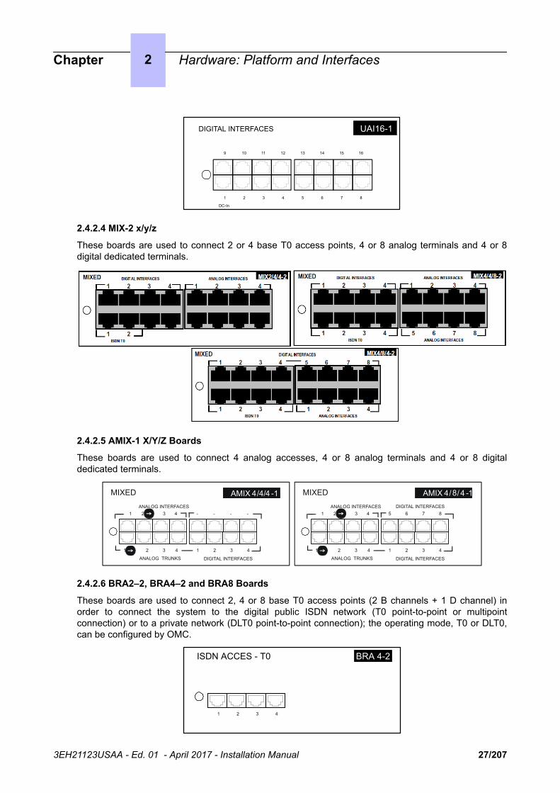
2.4.2.4 MIX-2 x/y/z
These boards are used to connect 2 or 4 base T0 access points, 4 or 8 analog terminals and 4 or 8digital dedicated terminals.
2.4.2.5 AMIX-1 X/Y/Z Boards
These boards are used to connect 4 analog accesses, 4 or 8 analog terminals and 4 or 8 digitaldedicated terminals.
MIXED
1 2 3 4 1 2 3 4
ANALOG INTERFACES
DIGITAL INTERFACES
1 2 3 4 - - - -
AMIX 4/4/4 -1
ANALOG TRUNKS
MIXED
1 2 3 4 1 2 3 4
ANALOG INTERFACES
DIGITAL INTERFACES
DIGITAL INTERFACES1 2 3 4 5 6 7 8
AMIX 4/8/4 -1
ANALOG TRUNKS
2.4.2.6 BRA2–2, BRA4–2 and BRA8 Boards
These boards are used to connect 2, 4 or 8 base T0 access points (2 B channels + 1 D channel) inorder to connect the system to the digital public ISDN network (T0 point-to-point or multipointconnection) or to a private network (DLT0 point-to-point connection); the operating mode, T0 or DLT0,can be configured by OMC.
ISDN ACCES - T0
1 2 3 4
BRA 4-2
Chapter 2 Hardware: Platform and Interfaces
3EH21123USAA - Ed. 01 - April 2017 - Installation Manual 27/207

2.4.2.7 PRA Boards
This board provides 1 primary access for connecting the OXO Connect system to the ISDN digitalpublic network or to private networks:
• PRA-T2, DLT2 : 30 x 64-Kbps B-channels + 1 x 64-Kbps D-channel; 2048 Kbps.• PRA-T1 : 23 x 64-Kbps B-channels + 1 x 64-Kbps D-channel; 1544 Kbps.• PCM R2: 30 x 64-Kbps B-channels + 1 x 4-Kbps signaling channel; 2048 Kbps.
The diagram below shows the end-plate of the PRA-T2 board, but the other PRA boards are similar.
ISDN ACCESS - E1
BUSY RAI AIS
NOS CRC LOS
PRA-T2
PBXNETW
2.4.2.7.1 Function of the LEDs
T2 Name T1 Name Function
BUSY BUSY B-channels busy (red LED lights up if at least 1 B-channel is busy)
RAI (ATD) RAI Remote frame alarm (red LED lights up on alarm)
AIS (SIA2M) AIS Too many "1's in the 2-Mbit binary train (red LED lights up on alarm)
NOS (MS) NSIG Absence of 2-Mbit signal (red LED lights up on alarm)
CRC (TE) CRC CRC error (red LED lights up on alarm)
LOS (PVT) NSYN Loss of frame alignment (red LED lights up on alarm)
2.4.2.8 APA Boards
This board is used to connect to the analog public network (2, 4 or 8 LR).
1 2 3 4
"Analog Public Access". APA8
5 6 7 8
The APA board does not support pulse dialing in Australia and New Zealand.
2.4.2.9 LanX-2 Boards
The LanX8-2 and LanX16-2 are second generation boards integrating respectively 1 or 2 EthernetGigabit ports for a Lanswitch/Layer 2 configuration. Any port can be used as an Uplink, as all the portsare auto MDI/MDIX.
Chapter 2 Hardware: Platform and Interfaces
3EH21123USAA - Ed. 01 - April 2017 - Installation Manual 28/207

Unlike the 1st generation boards, the LEDs of the A and B ports are both located at the top of theboard. The Led display is as follows:
• Green LED (left) = link status and activity:
• off: link disconnected• on: link connected• blinking: link active
• yellow LED (right) = speed:
• off: low speed (10 or 100 Mb for Gigabit port, 10 Mb for the other ports)• on: high speed (1 Gb for Gigabit port, 100 Mb for the other ports)
ETHERNET LANSWITCH
7 5 3 1
LanX8-2
B
A
GE1 246
manages ports 7, 5, 3 and 1
manages ports GE1, 6, 4 and 2
Ports
ETHERNET LANSWITCH
B
A
manages ports 7, 5, 3, 1, 14, 12, 10 and 8
manages ports GE1, 6, 4, 2, GE2, 13, 11 and 9
7 5 3 1
GE1 246
14 10 8
GE2 911
LanX16-2
12
13
Ports
2.4.2.10 Daughter Board Provision on PowerCPU EE Board
The table below presents the daughter boards which can be provided on the PowerCPU EE board,according to the platform used.
Daughter Boards OXO Connect Compact OXO Connect Small, Medium,Large
ARMADA VoIP32 Yes Yes
ARMADA VoIP64 Yes Yes
HSL1 No Yes
HSL2 No Yes
AFU-1 Yes Yes
Mini-Mix Yes No
Chapter 2 Hardware: Platform and Interfaces
3EH21123USAA - Ed. 01 - April 2017 - Installation Manual 29/207

Note:The Mini-MIX daughter board requires BACKXS-N back panel and PSXS-N power supply module. The Mini-MIXdaughter board can be used only in an OXO Connect Compact.
ARMADA VoIP32 or ARMADA VoIP64
(optional)
HSL1/HSL2(optional)
AFU(optional)
DDR2 Module (underneath)
Mini-MIX(optional)
HSL and Mini-MIX daughter boards
are not compatible
Mass Storage Daughter Board (MSDB) 8 GB equipped with eMMC (embedded Multi-Media Card)
Figure 2.2: Example of Daughter Boards on PowerCPU EE board
2.4.2.11 Provision By Platform2.4.2.11.1 OXO Connect Compact
Chapter 2 Hardware: Platform and Interfaces
3EH21123USAA - Ed. 01 - April 2017 - Installation Manual 30/207

Board MIX Slot CPU Slot
PowerCPU EE No Mandatory
MIX-2 x/y/z Yes No
AMIX-1 x/y/z Yes No
2.4.2.11.2 OXO Connect S
SLOT1 SLOT2 SLOT CPU
Boards Slots 1-2 CPU Slot
PowerCPU EE No Mandatory
MIX-2 x/y/z Yes No
AMIX-1 x/y/z Yes No
UAI4, UAI8, UAI16, UAI16-1 Yes No
SLI4-2, SLI8-2 Yes No
SLI16-2 No No
PRA-T2, PRA-T1, DLT2, PCM R2 Yes No
APA4, APA8 Yes No
BRA2-2, BRA4-2, BRA8 Yes No
LanX8-2, LanX16-2 Yes No
2.4.2.11.3 OXO Connect M
SLOT1 SLOT2
SLOT4SLOT3 SLOT5
SLOT CPU
Boards Slots 1-2-3-4-5 CPU Slot
PowerCPU EE No Mandatory
MIX-2 x/y/z Yes No
AMIX-1 x/y/z Yes No
UAI4, UAI8, UAI16, UAI16-1 Yes No
Chapter 2 Hardware: Platform and Interfaces
3EH21123USAA - Ed. 01 - April 2017 - Installation Manual 31/207

Boards Slots 1-2-3-4-5 CPU Slot
SLI4-2, SLI8-2, SLI16-2 Yes No
PRA-T2, PRA-T1, DLT2, PCM R2 Yes No
APA4, APA8 Yes No
BRA2-2, BRA4-2, BRA8 Yes No
LanX8-2, LanX16-2 Yes No
2.4.2.11.4 OXO Connect L
SLOT1 SLOT2
SLOT4
SLOT7SLOT6
SLOT3 SLOT5
SLOT8
SLOT CPU
Boards Slot 1 Slots 2-3-4 Slots5-6-7-8 CPU Slot
PowerCPU EE No No No Mandatory
MIX-2 x/y/z Yes Yes No No
AMIX-1 x/y/z Yes Yes No No
UAI4, UAI8 Yes Yes Yes No
UAI16, UAI16-1 Yes Yes No No
SLI4-2, SLI8-2, SLI16-2 Yes Yes Yes No
PRA-T2, PRA-T1, DLT2, PCM R2 Yes Yes Yes No
APA4 Yes Yes Yes No
APA8 Yes No Yes No
BRA2-2BRA4-2, BRA8 Yes Yes Yes No
LanX8-2, LanX16-2 Yes Yes Yes No
Chapter 2 Hardware: Platform and Interfaces
3EH21123USAA - Ed. 01 - April 2017 - Installation Manual 32/207

Chapter
3 System Services
3.1 Software Licence Management
3.1.1 Software licence managementOn an OXO Connect several types of devices may be connected, several services may be offered andseveral applications may run.
The purpose of the feature “Software Licence Management” is to define for a given system (i.e.customer) the service level to offer, this mainly means:
• What devices are allowed and how many of each type.• Which service is offered.• Which application is to open.• How many users are allowed.• What features the hardware can support.
The SWL (SoftWare Licence) files define the level of service requested.
The software licenses are the encoded result of the service levels and of a unique CPU ID. Theyshould be loaded during the installation of the system.
The software license can be managed by the normal mode. There is no user definition and the validityof the license in open state is not limited.
Note:In Normal mode , the SWL files are loaded to the system or updated manually using OMC
Once SWL files are available on the system in normal mode, it manages the following functions:
• Definition, modification and checking of the service level.• Dimensioning of a system for a correct service level.• Limitation of requested services depending on hardware installed.• Daily or on request checking (by OMC) of the SWL files in order to adapt the service level.• Information to user and/or installer about the state of system in terms of service level.
3.2 Software KeysIn the OXO Connect system, a software key is represented by an alphanumeric string of characters,which opens functions. Two software keys correspond to each OXO Connect system:
• the PRINC (PRINCIPAL) software key or MAIN for the system functions (voice, system feature,etc.)
• the CTI Software key for the CTI functions
The software key corresponds to a text file where the name is the CPU hardware number withthe .MSL (MAIN key) or .CSL (CTI key) extension.
Example:file 000068DA.msl and 000068DA.csl for main CPU no. 000068DA.
Each system needs the Main and CTI Software keys even if no CTI application is used on the system.
The systems can be delivered with a key that is already personalized for the client. The Distributorneeds to load if necessary the personalized key on the non-factory-configured systems.
3EH21123USAA - Ed. 01 - April 2017 - Installation Manual 33/207

On starting up the system, different cases are possible:
• The functions needed by the customer are open and work properly: the software key presenton the system is correct.
• The functions needed are not open• The key is valid but some functions are not open).
• Verify that the order meets the client's needs. If not, contact the orders" department. A newsoftware key needs to be created including the new features.
• When loading the key via OMC a warning message is displayed. In this case the functionalitiesmay be limited due to insufficient memory or CPU power.
• The software key present on the system is not correct:
• The software key syntax is correct but it does not match the CPU's serial number. The systemfunctions correctly with all its functionalities for 30 days. A message " Software Key Error " isdisplayed on the Operator terminal. Press the Alarm key to show the expiry date. When loadinga correct key (valid CPU serial number) during this period, the system state is normal. If nocorrect key is loaded after 30 days, the system will restart in limited state with only setsbelonging to the Operator group working, all other sets being out of service; the "Software keyerror" is displayed on the operator station.
• The software key syntax is incorrect. The system starts in limited mode. When loading thecorrect Software key (with the correct serial number), the system restarts with all functionsworking.
• The software key syntax is correct, the software release is correct but a more recent key hasalready been entered on this system and it is not possible to revert to a previous key. Thesystem functions correctly with all its functionalities for 30 days.
• The software key syntax is correct, but the software key does not match the system's softwarerelease. The system functions correctly with all its functionalities for 30 days.
Remark:For a system in limited mode, when a valid software key is loaded, the system restarts with all its functionalities.
3.2.1 Voice Services Available in "Limited" Mode• 2 "normal" TDM sets, stations in the default Attendant Group and analog sets with automatic call
setup on going off-hook• no DECT stations, including TDM (wired reflex) stations• Voice server with name announcement, 2 ports and 20 minutes" storage• 4 welcome messages (pre-announcement)• 2 system languages• "Please Wait" music: 2 minutes max.• All the other functions are closed.
3.2.2 Software Key ChangeIn BTCO mode, the software key is loaded into the system by the manufacturer; in "stock mode" (aftersale), the key must be entered by the distributor. When upgrading, the installer must modify the keybefore the new functions will be taken into account.
The key is modified using OMC or DHM-station.
3.2.2.1 Procedure with OMC
• To read the series number of a CPU board: Select Typical Modification -> System -> Softwarekey -> Hardware serial number
• Send this serial number and the function levels required to ALE International
Chapter 3 System Services
3EH21123USAA - Ed. 01 - April 2017 - Installation Manual 34/207

• Load the key file Main.msl or CTI.csl from the ALE International Business Partner web site (this filecan also be downloaded by the manufacturer)
• Downloading a new software key:
• Select Typical Modification -> System -> Software key• Click on Importing the key• On the Open screen, select the file for the new software key• Validate• On the Software Key screen, click on Apply
• Opening certain functions requires a hot reset; a message is displayed.
If the hardware required to carry out the functions that have been opened by the software key is notpresent, the functions available are automatically reduced to suit the available hardware; and errormessage is displayed when the key is implemented.
The values of the various functions controlled by the key can be viewed at any moment:
• Using OMC, select Typical Modification -> System -> Software key• Click on Details: the first column indicates the functions defined by the key, the second column
indicates the functions actually open (after any reductions).
3.3 Cloud Connect Operation (CCO)
3.3.1 Cloud Connect Operation overviewCloud Connect Operation (CCO) is designed to ease the deployment of OXO Connect, by simplifyingthe installation, allowing remote/centralized management in a full IP trunk environment and offeringfleet supervision services.
CCO is based on an XMPP global infrastructure (Cloud Connect Infrastructure). When CCO is enabledfor the first time, OXO Connect registers to the FTR service and connects to the Cloud ConnectInfrastructure (CCI).
After connection to the CCI, a permanent link is maintained, allowing the OXO Connect to be reachablevia VPN connection (for configuration purpose with OMC for instance) and “Get Files” feature.
This link allows the establishment of a VPN tunnel from the OXO Connect to a VPN gateway. This VPNtunnel can be used for remote management with existing configuration tools (OMC, web-based tool(WebDiag), AST, …).
Both XMPP permanent and on demand VPN connections are established by OXO Connect. Becausethese connections are outgoing from CPE LAN to the WAN, there is no need to modify basic firewallrules.
The CCO solution is detailed in: 8AL91354ENAA Cloud Connect Operation Overview
For more information on CCO activation, see: Enabling/Disabling CCO on OXO Connect on page 36.
Chapter 3 System Services
3EH21123USAA - Ed. 01 - April 2017 - Installation Manual 35/207

3.3.2 Registration of the product
3.3.3 Configuring CCO on OXO Connect
3.3.3.1 Associating the order with the CPUID
The association between the order identified by the CC-Suite-ID and the Hardware ID of the CPU ismandatory to use the CCO services.
In case of BTCO, this is done at industrialization/integration step.
In case of non BTCO, before product installation:
1. Connect to eLP2. Select an order3. Associate the Hardware-ID of a CPU to the CC-Suite-ID
This creates the requested accounts to connect to the CCI.
3.3.3.2 Enabling/Disabling CCO on OXO Connect
To Enable/disable CCO:
• By OMC:
1. Select Cloud > Cloud Connect2. Check/uncheck the box: Cloud Connect enabled
• By MMC (administrator session):
1. Go to System > cConnect2. Press Choice to enable/disable Cloud Connect
After enabling CCO, OXO Connect connects to the CCI. In case of connection failure, the OXOConnect periodically retries:
• Every 5 minutes during the first two hours• After the first two hours, the delay is doubled after each attempt, but cannot exceed 12 hours
At any time, it is possible to trigger a connection attempt by disabling and re-enabling CCO. This resetsthe delay between two attempts in case of connection failure.
3.3.4 Maintenance
3.3.4.1 Replacing a CPU
To replace a CPU:
1. Perform rehosting on eLP. The Activation Account of the new CPU has to be activated in the CCI2. Replace the CPU and restore the configuration
The CPU connects to the CCI if enabled in the configuration, and makes a new FTR.
3.3.4.2 CPU swap with same hardware
CPU swap with same hardware is necessary in case of wrong association between hardware andorder in eLP. The CPU installed at customer 1 is associated with the customer 2 order and vice versa.The CPUs have retrieved the wrong licenses (CPU at customer 1 has licenses for customer 2 and CPUat customer 2 has licenses for customer 1).
To solve the problem: swap the CPUs in eLP. The Activation Accounts of the both CPUs must beactivated in the CCI.
The CPUs are associated to the correct order. Both CPUs make a new FTR.
Chapter 3 System Services
3EH21123USAA - Ed. 01 - April 2017 - Installation Manual 36/207

3.3.4.3 CPU swap with different hardware
CPU swap with different hardware is necessary when two CPUs for two different customers have beenswitched at installation and have different hardware (Armada daughter board for instance).
To solve the problem:
1. swap CPUs on the field (standard procedure)2. Save configuration on old CPU and restore on new CPU by OMC.
3.4 CCO VPN serviceThe CCO VPN service allows to establish a VPN tunnel between OXO Connect and a VPN gateway.
By using CCI, an application can request the connection of OXO Connect to a VPN gateway. Thisconnection to the VPN gateway is initiated by OXO Connect through an outbound connection from theLAN to the WAN. A VPN tunnel is established between the OXO Connect system and the VPNgateway. Then the requesting application gets access only to OXO Connect through the VPN gateway,it does not have access to the OXO Connect LAN.
The connection to the VPN gateway is established on demand.
When CCO VPN is enabled, the V34 and ISDN connection are still allowed, and can be used inparallel.
For more information on the deployment of VPN over Cloud Connect infrastructure, refer to:8AL91215ENAA Cloud Connect VPN server reference design for OXO Connect
3.4.1 CCO VPN service ArchitectureFigure 1 shows the main components involved in VPN CCO service and their relations.
Chapter 3 System Services
3EH21123USAA - Ed. 01 - April 2017 - Installation Manual 37/207

CC Infrastructure
VPN Gateway
Connection Agent
Service XVPN Agent Service Y
Application X
Application Application Y
Service
Tunnel
OXO Connect
VPN connection request
2
Application data 4
connection service
IAD : Firewall / NAT
Remote Service Center
1
3 OXO VPN IP @
CC permanent connectionInternet / WAN
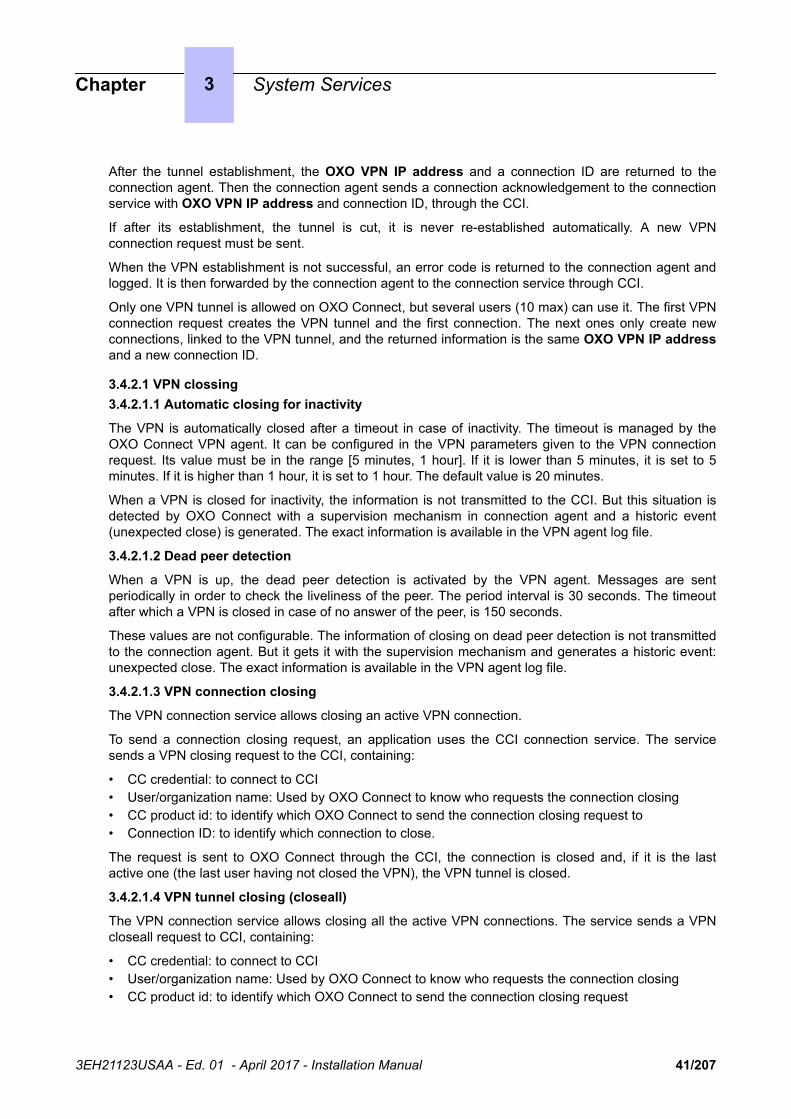
Figure 3.1: CCO VPN service architecture
When CCO is enabled, OXO Connect establishes and maintains a permanent connection to CCOinfrastructure (blue arrow).
To establish a VPN with OXO Connect:
• The application sends a VPN connection request to OXO Connect via the Connection service (1)• OXO Connect establishes an outband VPN connection with the VPN gateway (2), and returns its
VPN IP address to the application (3)• The application connects to the VPN gateway and can exchange data with OXO Connect (4)
Some carriers manage their own CCI to access their OXO Connects. The connection from ALE CCI isstill possible, but is controlled by the Service Activation in the carrier CCI. When a VPN connectionrequest is sent from the ALE service center to an OXO Connect managed by a carrier, the request is
Chapter 3 System Services
3EH21123USAA - Ed. 01 - April 2017 - Installation Manual 38/207
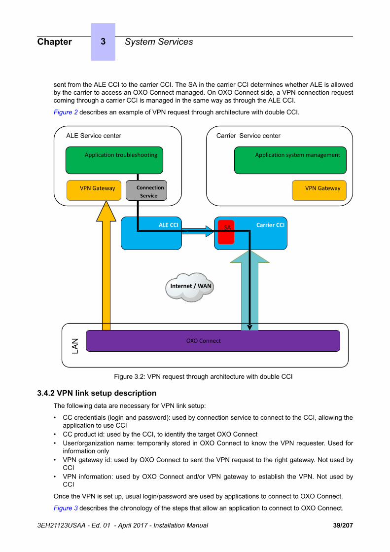
sent from the ALE CCI to the carrier CCI. The SA in the carrier CCI determines whether ALE is allowedby the carrier to access an OXO Connect managed. On OXO Connect side, a VPN connection requestcoming through a carrier CCI is managed in the same way as through the ALE CCI.
Figure 2 describes an example of VPN request through architecture with double CCI.
OXO Connect
Internet / WAN
LAN
ALE CCI Carrier CCI
VPN Gateway
Application system management
VPN Gateway
Application troubleshooting
ALE Service center
SA
Carrier Service center
Connection Service
Figure 3.2: VPN request through architecture with double CCI
3.4.2 VPN link setup descriptionThe following data are necessary for VPN link setup:
• CC credentials (login and password): used by connection service to connect to the CCI, allowing theapplication to use CCI
• CC product id: used by the CCI, to identify the target OXO Connect• User/organization name: temporarily stored in OXO Connect to know the VPN requester. Used for
information only• VPN gateway id: used by OXO Connect to sent the VPN request to the right gateway. Not used by
CCI• VPN information: used by OXO Connect and/or VPN gateway to establish the VPN. Not used by
CCI
Once the VPN is set up, usual login/password are used by applications to connect to OXO Connect.
Figure 3 describes the chronology of the steps that allow an application to connect to OXO Connect.
Chapter 3 System Services
3EH21123USAA - Ed. 01 - April 2017 - Installation Manual 39/207

8 : Connection Ack (OXO VPN IP@)
7 : Connection Ack (OXO VPN IP@)
Cust
omer
Data
10 : Use application
1 : Connect
9 :Appli login
(OXO VPN IP@, OXO login/pwd)
Customer network
VPN
Gateway
Connection service
DB
Customer database:- CC product id
Remote Service Center
CCI
2 : Connection request
Application
3 : Authentication& access control
4 : Connection request
5 : tunnel setup
(VPN GW id) 6 : Connection Ack (OXO VPN IP@)
OXO ConnectService
VPN Agent Connection agent
Cloud connect
- CC credentials- User/org name- VPN GW id- VPN info
(VPN GW id, VPN info, U/O name)
(CC cred, CC prod id, VPN GW id, VPN info, U/O name)
(CC cred, CC prod id, VPN GW id, VPN info, U/O name)
Figure 3.3: VPN connection setup
Chapter 3 System Services
3EH21123USAA - Ed. 01 - April 2017 - Installation Manual 40/207
After the tunnel establishment, the OXO VPN IP address and a connection ID are returned to theconnection agent. Then the connection agent sends a connection acknowledgement to the connectionservice with OXO VPN IP address and connection ID, through the CCI.
If after its establishment, the tunnel is cut, it is never re-established automatically. A new VPNconnection request must be sent.
When the VPN establishment is not successful, an error code is returned to the connection agent andlogged. It is then forwarded by the connection agent to the connection service through CCI.
Only one VPN tunnel is allowed on OXO Connect, but several users (10 max) can use it. The first VPNconnection request creates the VPN tunnel and the first connection. The next ones only create newconnections, linked to the VPN tunnel, and the returned information is the same OXO VPN IP addressand a new connection ID.
3.4.2.1 VPN clossing3.4.2.1.1 Automatic closing for inactivity
The VPN is automatically closed after a timeout in case of inactivity. The timeout is managed by theOXO Connect VPN agent. It can be configured in the VPN parameters given to the VPN connectionrequest. Its value must be in the range [5 minutes, 1 hour]. If it is lower than 5 minutes, it is set to 5minutes. If it is higher than 1 hour, it is set to 1 hour. The default value is 20 minutes.
When a VPN is closed for inactivity, the information is not transmitted to the CCI. But this situation isdetected by OXO Connect with a supervision mechanism in connection agent and a historic event(unexpected close) is generated. The exact information is available in the VPN agent log file.
3.4.2.1.2 Dead peer detection
When a VPN is up, the dead peer detection is activated by the VPN agent. Messages are sentperiodically in order to check the liveliness of the peer. The period interval is 30 seconds. The timeoutafter which a VPN is closed in case of no answer of the peer, is 150 seconds.
These values are not configurable. The information of closing on dead peer detection is not transmittedto the connection agent. But it gets it with the supervision mechanism and generates a historic event:unexpected close. The exact information is available in the VPN agent log file.
3.4.2.1.3 VPN connection closing
The VPN connection service allows closing an active VPN connection.
To send a connection closing request, an application uses the CCI connection service. The servicesends a VPN closing request to the CCI, containing:
• CC credential: to connect to CCI• User/organization name: Used by OXO Connect to know who requests the connection closing• CC product id: to identify which OXO Connect to send the connection closing request to• Connection ID: to identify which connection to close.
The request is sent to OXO Connect through the CCI, the connection is closed and, if it is the lastactive one (the last user having not closed the VPN), the VPN tunnel is closed.
3.4.2.1.4 VPN tunnel closing (closeall)
The VPN connection service allows closing all the active VPN connections. The service sends a VPNcloseall request to CCI, containing:
• CC credential: to connect to CCI• User/organization name: Used by OXO Connect to know who requests the connection closing• CC product id: to identify which OXO Connect to send the connection closing request
Chapter 3 System Services
3EH21123USAA - Ed. 01 - April 2017 - Installation Manual 41/207

The request is sent to OXO Connect through the CCI, and all the active connections and the VPNtunnel are closed.
3.5 Rainbow
3.5.1 Rainbow overviewRainbow is a cloud based software system providing services to end users, such as remote call controland rich telephony presence.
Services provided to end users are either fully managed by the Rainbow infrastructure, or linked to theOXO Connect, such as telephony presence (mixed with IM and video presence in Rainbow) or basictelephony features (make call, transfer, or three-party conference).
The Cloud Connect Control Agent component (CCCtrlA), embedded on the OXO Connect, allows toestablish a secure connection with the Rainbow infrastructure, using WebSocket Secure (WSS). OnRainbow side, the access point is a PBX Cloud Gateway (PCG). The CCCtrlA is also used by Rainbowto retrieve the list of OXO Connect devices.
For the list of OXO Connect sets supported by Rainbow, refer to the feature list and cross compatibility.
3.5.2 Rainbow deployment
3.5.2.1 Engineering rules/prerequisites
LAN on customer side must be configured to give the possibility to OXO Connect to initiate a WSSconnection to Rainbow infrastructure:
• If present on site, the firewall must authorize outgoing WSS link to port 443• If present on site:
• The proxy must redirect WSS protocol to the Internet• The proxy must be configured on OXO Connect in OMC in Hardware and Limits > LAN / IP
Configuration > Web proxy tab.
Note:CCCtrlA uses the same proxy configuration as Cloud Connect Operation.
3.5.2.2 Enabling/disabling CCtrlA
• By OMC:
1. Select Cloud > Rainbow2. Check/uncheck the box: Rainbow enabled3. Configure Rainbow connection parameters, see: Configuring Rainbow on page 424. Click OK
• By MMC (administrator session):
1. Go to System > Rainbow2. Press Choice to enable/disable CCCtrlA
Note:Enabling/disabling CCtrlA does not reinitiaze connection parameters already configured.
3.5.2.3 Configuring Rainbow
When Rainbow is enabled, le following parameters must be configured:
1. In OMC (Expert View), select Cloud > Rainbow
Chapter 3 System Services
3EH21123USAA - Ed. 01 - April 2017 - Installation Manual 42/207

2. Review/modify the followings attributes:
Rainbow PBX ID Enter the identifier of the OXO Connect in Rainbow infrastruc-ture. By default, this field is completed with the CPU serial num-ber.
This field is mandatory when the Rainbow enabled check boxis enabled.
Domain Enter the domain name of the Rainbow infrastructure. To ac-cess the Rainbow infrastructure, OXO Connect generates theFQDN using the Rainbow domain name. This domain name isthe same for every OXO Connect. By default, the Rainbow do-main name is initialized to openrainbow.com.
This field is mandatory when the Rainbow enabled check boxis enabled.
Activation Code Enter the activation code used by the CCCtrlA when it connectsto the Rainbow infrastructure for the first time. This code mustbe provided by the Rainbow infrastructure administrator in orderto be able to authenticate the OXO Connect on the Rainbow in-frastructure during the initial login phase.
This field is mandatory when the Rainbow enabled check boxis enabled.
After connection to the Rainbow infrastructure and reception ofthe login password, this field is grayed.
If you need to modify the Activation Code, click the Reset but-ton to reset the login to the Rainbow servers and enter the newActivation Code.
Caution:Pressing the Reset button will disable the Rainbow connection.
Password This field is read-only. It displays the login password sent by theRainbow infrastructure after connection. It corresponds to thelast 8 characters taken from an encrypted password using theSHA-256 algorithm.
Connection Status This field displays the status of the connection with the Rainbowinfrastructure:
• Connected: a connection is established with the Rainbowinfrastructure.
• Disconnected: a connection is not yet established, or thereis a problem with the connection to the Rainbowinfrastructure. This can occur when the CCCtrlA is stopped.
Click the Status update button to update the Connection Sta-tus.
3. Click Apply
3.5.2.4 Rainbow initialization
To access to the Rainbow infrastructure, OXO Connect generates the FQDN using Rainbow domain.This domain is the same for all OXO Connects.
Chapter 3 System Services
3EH21123USAA - Ed. 01 - April 2017 - Installation Manual 43/207

The generated FQDN is: wss://agent.[Rainbow domain]:443OXO Connect resolves the generated FQDN to establish the link to Rainbow infrastructure.
In case of connection failure, CCCtrlA periodically retries to connect to PCG after 10 sec, 30 sec,1 min, 2 min, 4 min, 8 min, and every 16 min.
At any time, it is possible to trigger a connection attempt by disabling and re-enabling the CCCtrlAconnection setting, see Enabling/disabling CCtrlA on page 42.
This also resets the delay between the attempts in case of connection failures.
Chapter 3 System Services
3EH21123USAA - Ed. 01 - April 2017 - Installation Manual 44/207

Chapter
4 Installation and Cabling
4.1 Presentation
4.1.1 Location of UnitThe OXO Connect unit can be installed in three ways:
1. Fixed to the wall:
• A kit is available for wall-mounting OXO Connect S and OXO Connect M platforms.• A wall support (US version) is available for wall-mounting OXO Connect Compact platform which
can also be fixed directly to the wall. In both cases, use the hole drilling template supplied withthe platform.
2. Mounted in a rack: the OXO Connect Small, Medium, Large platforms are mounted in the rack usingthe fixing brackets supplied by the rack manufacturer, or using the optional 19" mounting kit (a kit isavailable for each platform type).
3. Placed on a table: no more than three units can be laid on top of each other.
4.1.1.1 Wall Mounting (OXO Connect S and OXO Connect M platforms)
The enclosure comprises 4 parts.
After mounting, the space between the platform and the wall can be used for cables.
to platform (2 screws)
of platform
Special part (A) depending on platform;to be attached to platform by 2 screws
to be attached to platform
3EH21123USAA - Ed. 01 - April 2017 - Installation Manual 45/207

4.1.1.2 Mounting in the 19" Rack
Right-hand support rail
Left-hand support rail
Unit locking studs
4.1.1.2.1 Recommendations
Before installing the system in a 19" rack, you must verify that:
• The maximum static load (given by the manufacturer) of the 19" rack is greater than the overallweight of the equipment mounted or to be mounted in the rack.
• Moreover, the weight of the equipment must be evenly distributed between the brackets.• If mounting the OXO Connect platform results in exceeding the load on the front supports (generally
the total weight divided by two), the platform must be placed on a fixed tray attached to the foursupports of the rack.
4.1.2 Environment
4.1.2.1 Climatic Conditions
• Operation
• Temperature: for maximum reliability, it is recommended you comply with an ambienttemperature of between 5 and 40 degrees Celsius, with a maximum variation of 5 degreesCelsius per hour.
Chapter 4 Installation and Cabling
3EH21123USAA - Ed. 01 - April 2017 - Installation Manual 46/207

• Humidity: the humidity must be in the range 10% - 80% (no condensation) with a maximumvariation of 10% per hour.
• Storage
• Temperature: the temperature must be kept between -20 and +70 degrees Celsius.• Humidity: the humidity must be kept in the range 10 - 95% (no condensation).
4.1.2.2 Vibration
No vibration, even intermittent, may be transmitted to the equipment when running.
4.1.2.3 Site
• Choose a dry, clean and well ventilated location.• Maintain an ambient air flow to ensure normal ventilation. If the air flow is blocked or restricted, of
the incoming air is too hot, overheating is possible.• When installing the equipment in an enclosed 19" rack, verify that the rack is provided with a fan
suited to the heat dissipation of the equipment installed. Maintain a minimum gap of 3 cm aroundthe side ventilation holes (left and right sides), and of 10 cm minimum around the ventilation holesat the rear of the equipment. Verify that the air flow is not impeded on the sides of the rack.
• When fixing the system directly to the wall using the wall-mounting kit (OXO Connect S and OXOConnect M platforms only), maintain a free space of at least 15 cm around the whole system.Ensure that no objects are placed on the upper part of the system to restrict the extraction of hot air.When installing several platforms, it is preferable to align then horizontally. When superposing themvertically, they should be separated by at least 10 cm.
• Verify that the cables connecting the OXO Connect or other equipment, or the supports for thehousing structure (19" rack for example) do not obstruct the air flow through the platform.
• A switchable 230 V or 110 V mains socket (according to country) - 50Hz (LNE) is required at lessthan 1 m from the platform unless it is installed in a rack in which case the integrated circuit breakeris used.
• Adequate lighting must be provided.
4.2 Connections and Cabling
4.2.1 Output ConnectorsAll outputs are made using Female RJ45 connectors.
12345678
Front panel RJ45 female connector
4.2.1.1 PowerCPU EE Board
RJ45 pin 1 2 3 4 5 6 7 8
LAN TX+ TX- RX+ RX-
SLI1/SLI2 Ground +12 V CenRgA ZA1 ZB1 CenRG
B ZA2 ZB2
Chapter 4 Installation and Cabling
3EH21123USAA - Ed. 01 - April 2017 - Installation Manual 47/207

AUX Ground +12 V CenRgA
CenRGB
CONFIG CTS RX RMTRES Ground TX DTR RTS
MODULE1 TX+ TX- RX+ RX-
ISDN T01 TX+ RX+ RX- TX-
MODULE2 TX+ TX- RX+ RX-
ISDN T02 TX+ RX+ RX- TX-
AUDIO Audio InA
Audio InB
AudioCtrl A
AudioOut A
AudioOut B
AudioCtrl B Alarm A Alarm B
DOORPHONE DoorPhB1
Door-PhA1
Door-PhA2
DoorPhB2
• LAN: 10/100/1000 base T Ethernet port (MDI-II/straight).• SLI1/SLI2: Analog Z accesses from Mini-MIX board, General ringer; 12V output• AUX: General ringer; 12V output• CONFIG: RS232 for OMC.• MODULE1: HSL1 link of HSL board for connection to module expansion 1• ISDN T01: ISDN T01 port of Mini-MIX board• MODULE2: HSL2 link of HSL board for connection to module expansion 2• ISDN T02: ISDN T02 port of Mini-MIX board• AUDIO: Interfaces Please wait message, Background music, Loudspeaker, Alarm• DOORPHONE: Interfaces doorphone
4.2.1.2 SLI-2 Board
RJ45 pin 1 2 3 4 5 6 7 8
1 to 16 ZA ZB
• 1 to 16: connecting analog Z terminals.
4.2.1.3 UAI Board
RJ45 pin 1 2 3 4 5 6 7 8
1 to 16 (UAI) L1 L2
• 1 to 16: connection of digital terminals or DECT 4070 IO/EO base stations.
4.2.1.4 UAI-1 Board
RJ45 pin 1 2 3 4 5 6 7 8
1 L1 L2 0V 48V
Chapter 4 Installation and Cabling
3EH21123USAA - Ed. 01 - April 2017 - Installation Manual 48/207

2 to 16 L1 L2
• 1 : connection of an EPS48 external power supply + connection of digital terminals or DECT 4070IO/EO base stations.
• 2 to 16: connection of digital terminals or DECT 4070 IO/EO base stations.
4.2.1.5 BRA-2 Board
RJ45 pin 1 2 3 4 5 6 7 8
1 to 8 TX+ RX+ RX- TX-
• 1 to 8: connection of T0/DLT0 basic access.
4.2.1.6 PRA Board
RJ45 pin 1 2 3 4 5 6 7 8
NETW outputs RX+ RX- TX+ TX-
PBX outputs TX+ TX- RX+ RX-
• NETW: connection to the public network (TNL).• PBX: use in private network with TX and RX twisted pairs.
4.2.1.7 LanX-2 Board
RJ45 pin 1 2 3 4 5 6 7 8
Ports 1 to 14 RX+ RX- TX+ TX-
GE1, GE2 TR0+ TR0- TR1+ TR2+ TR2- TR1- TR3+ TR3-
• Ports 1 to 14: 10/100 BT ports.• GE1, GE2: 10/100/1000 BT ports.
4.2.1.8 APA Board
RJ45 pin 1 2 3 4 5 6 7 8
Output 1 ZSETB ZSETA LB-Ring LA-Tip ZB ZA
Outputs 2 to 8 LB-Ring LA-Tip
• 1 : connection of network line 1, SLI interface and callback terminal• 2 to 8: connection of other analog trunk lines
4.2.2 Types of Cable to Use
Access Type Impedance
Digital, Z, T0, LR UTP, FTP or STP, Category 3 or 5 100 or 120 ohms
Chapter 4 Installation and Cabling
3EH21123USAA - Ed. 01 - April 2017 - Installation Manual 49/207

T2 UTP, FTP or STP, Category 3 or 5 120 Ohms
T1 UTP, FTP or STP, Category 3 or 5 120 Ohms
Ethernet FTP or STP, Category 5 100 Ohms
HSL STP supplied with the product, Category 5 100 Ohms
• UTP: Unshielded Twisted Pairs• FTP: Foiled Twisted Pairs• STP: Shielded Twisted Pairs
4.2.3 Connection of PowerCPU EE Board
PROCESSING UNIT Power CPU EE
Power MEX
Power MEX
ETHERNET LANSWITCH LanX8-2
12V serviceable voltage
External LAN Switch
PC (OMC, NMC)
Doorphone
Power MEX board (extension unit) 1
Power MEX board (extension unit 2)
Power CPU board
LanX-2 board
MODULE EXPANSION
MODULE EXPANSION
General bell
Background musicLoudspeakerAlarm
"Please wait" message
4.2.4 Connecting Terminals
4.2.4.1 Connection of Digital Terminals
The terminals are equipped with a cable and a self-acting switch that plugs into the wall socket. Eachterminal is connected up by a pair of 0.5 or 0.6 mm diameter wires.
System - digital terminal distances:
• 0.5 mm SYT type cable: 800 m (station without option) or 600 m (station with S0 or Z option).
Chapter 4 Installation and Cabling
3EH21123USAA - Ed. 01 - April 2017 - Installation Manual 50/207

• 278 type 0.6 mm cable: 1200 m (station without option) or 850 m (station with S0 or Z option).
4.2.4.1.1 Connection without External Power Supply
L2 (5)
L1 (4)
Distribution panel DIGITAL INTERFACES UAI16
1 2 3 4 5 6 7 8
9 10 11 12 13 14 15 16
4.2.4.1.2 Connection with External Power Supply
A splitter allows the separation of the UA peripheral connection and the EPS48 external power supply.
L25
L14Distribution panel DIGITAL INTERFACES UAI16-1
1 2 3 4 5 6 7 8
9 10 11 12 13 14 15 16
1
Splitter
1 1
EPS48
+L Groundclass 1
4.2.4.2 Connecting Analog Terminals
The terminals are equipped with a cable and a self-acting switch that plugs into the wall socket. Eachterminal is connected up with a pair of 0.5 or 0.6-mm diameter wires (the maximum distance with 0.5-mm cabling is 1.3 km).
Chapter 4 Installation and Cabling
3EH21123USAA - Ed. 01 - April 2017 - Installation Manual 51/207

ZB
ZA
13
5
24
6
9 10 11 12 13 14 15 16
1 2 3 4 5 6 7 8
ANALOG INTERFACES SLI16-2
ZB (5)
ZA (4)
Distribution panel
or
4.2.5 Connection to the Public Network
4.2.5.1 Digital Public Network via T0 Access (or DLT0 Private Network)
The OXO Connect system can be installed near the digital network termination or at a certain distance(up to 350 m), as required.
4.2.5.1.1 Connection without T0/S0 Forwarding
Distribution panel
DNT
Transmission
Reception
TX
RX
ISDN ACCESS - T0
1 2 3 4 5 6 7 8
BRA8-2
Caution:In T0 Point-to-Point installations, the OXO Connect system MUST BE the terminating element of the busand any other terminating resistor MUST BE removed.
4.2.5.2 Digital Public Network by T1 or T2 Access
The diagram below shows a PRA-T2 board, but is equally applicable for a PRA-T1 board.
TX
RX
ISDN ACCESS - E1
PBXNETW
PRA-T2
BUSY RAI AIS
NOS CRC LOS
Distribution panel
DLT
Transmission
Reception
The PRA board is connected to a digital line termination (DLT) by 2 symmetrical twisted pairs.
Cable impedance: 120 Ohms +/- 20% between 200kHz and 1MHz; 120 Ohms +/- 10% at 1 MHz.
Chapter 4 Installation and Cabling
3EH21123USAA - Ed. 01 - April 2017 - Installation Manual 52/207

Remark:We recommend using an L120-series cable (or the L204 equivalent).
The distance T1-DLT or T2-DLT is limited by the amount of loss between the DLT and T1/T2, whichmust not exceed 6 dB at 1024 kHz.
4.2.5.3 Analog Public Network4.2.5.3.1 Without TL Forwarding
Distribution panelANALOG TRUNK ACCESS ATA 4
1 2 3 4
PEA
PEB
ANALOGPUBLIC
NETWORK
4.2.5.3.2 With LR Forwarding
In the event of a loss of tension or PowerCPU EE malfunction, this solution allows forwarding of theanalog line, connected to the APA board's equipment 1, to an analog station.
ANALOG INTERFACES SLI16-2
LB-Ring
LA-Tip
Distribution panel
"Analog Public Access". APA8
NetworkPublicAnalog
Setsubscriber.
ZSETA
ZSETB
ZA, ZB
Chapter 4 Installation and Cabling
3EH21123USAA - Ed. 01 - April 2017 - Installation Manual 53/207

4.2.5.4 Analog Public Network - Direct Dialing In.
L+
L-Distribution panel DIRECT DIALLING INWARD DDI4
NetworkPublicAnalog
4.2.6 LAN ConnectionThe LanX8-2/LanX16-2 board is used to connect servers, PCs, IP terminals and external switches.
PROCESSING UNIT
SWITCH
Alcatel
Port 1
Port 2
Port 3
Port 4
Up-Link
ETHERNET LANSWITCH
Ethernet 10/100 Mbits
Ethernet 10/100 Mbits
Ethernet 10/100 Mbits
Ethernet 10/100 Mbits
Ethernet 10/100 Mbits
Host 1
Host 2
Host 3
LanX8-2PowerCPU EE
Server 2
Server 1
Category 5 cable, FTP or STP, impedance 100 Ohms: maximum length 100 m.
Chapter 4 Installation and Cabling
3EH21123USAA - Ed. 01 - April 2017 - Installation Manual 54/207

4.2.7 Connecting Auxiliary EquipmentAll auxiliary equipment is connected via the AUDIO, AUX and DOORPHONE connectors of thePowerCPU EE board.
4.2.7.1 Connecting a Please-Wait Message Player
This is connected via the AUDCTRL output (control contact open when idle) and the AUDIN input ofthe AUDIO connector.
BUSINESS PROCESSING UNIT
LAN
LAN CONFIG.
DOORPHONEAUDIO MODULEMODULE 1
FAN POWER
CPUMODULE 2
AUX
ISDN T0 1 ISDN T0 2
SLI1/2 &
Mini-MIX
Audio In B
AudCrtl A
Distribution panel
Audio In A
AudCrtl B
Power supply
Audio Circuit
Controlcircuit
PowerCPU EE
4.2.7.1.1 Audio Input Characteristics:
Input impedance : 600 Ohms
4.2.7.1.2 Fuse Characteristics:
• Max. power : 10 W• Max. voltage : 60 V• Max. current : 500 mA
The contacts of the alarm and doorphone controls have the same electrical characteristics asthose indicated above.
4.2.7.2 Connecting a Background Music Tuner
This is connected via the AUDIN input of the AUDIO connector.
Distribution panel
Audio In B
Audio In A
Power supply
TUNER
BUSINESS PROCESSING UNIT
LAN
LAN CONFIG.
DOORPHONEAUDIO MODULEMODULE 1
FAN POWER
CPUMODULE 2
AUX
ISDN T0 1 ISDN T0 2
SLI1/2 &
Mini-MIX
PowerCPU EE
4.2.7.2.1 Audio Input Characteristics:
• Input impedance : 600 Ohms• Input level: access + 4.7 dBr or + 15 dBr
Chapter 4 Installation and Cabling
3EH21123USAA - Ed. 01 - April 2017 - Installation Manual 55/207

4.2.7.3 Connecting an Alarm
The alarm is activated in the event of a false stopping of the system.
It is connected via the ALARM output (control contact closed when idle) of the AUDIO connector.
BUSINESS PROCESSING UNIT
LAN
LAN CONFIG.
DOORPHONEAUDIO MODULEMODULE 1
FAN POWER
CPUMODULE 2
AUX
ISDN T0 1 ISDN T0 2
SLI1/2 &
Mini-MIX
Distribution panel
Alarm B
Alarm A
Power supply
Alarmsystem
PowerCPU EE
4.2.7.4 Connecting a Broadcast Loudspeaker
Broadcast loudspeakers are connected via the AUDOUT output of the AUDIO connector.
BUSINESS PROCESSING UNIT
LAN
LAN CONFIG.
DOORPHONEAUDIO MODULEMODULE 1
FAN POWER
CPUMODULE 2
AUX
ISDN T0 1 ISDN T0 2
SLI1/2 &
Mini-MIX
Distribution panel
Aud Out B
Aud Out A
Power supply
Amplifier
PowerCPU EE
4.2.7.4.1 Audio Output Characteristics:
• Output impedance: < 500 Ohms• Output level: access + 3 dBr
4.2.7.5 Connecting a General Ringer
The general ringer is connected via the CENRG output of the AUX connector.
Distribution panel
CenRg B
CenRg A
Power supply
Generalcall ringer
BUSINESS PROCESSING UNIT
LAN
LAN CONFIG.
DOORPHONEAUDIO MODULEMODULE 1
FAN POWER
CPUMODULE 2
AUX
ISDN T0 1 ISDN T0 2
SLI1/2 &
Mini-MIX
PowerCPU EE
Chapter 4 Installation and Cabling
3EH21123USAA - Ed. 01 - April 2017 - Installation Manual 56/207

4.2.7.6 Connecting a Doorphone
2 doorphone types are available, depending on the operating mode used:
• Type A: relay-controlled doorphones (e.g. NPTT)• Type B: doorphones controlled by MF Q23 signals requiring an SLI interface (e.g. TELEMINI and
UNIVERSAL DOORPHONE)
The doorphone interface comprises an intercom and an optional latch powered by the mains supplythrough a SELV (Safety Extra Low Voltage) transformer.
It is connected via the DOORPHA and DOORPHB outputs (control contacts open when idle) of theDOORPHONE connector.
4.2.7.6.1 Connecting a NPTT DoorphoneBUSINESS PROCESSING UNIT
LAN
LAN CONFIG.
DOORPHONEAUDIO MODULEMODULE 1
FAN POWER
CPUMODULE 2
AUX
ISDN T0 1 ISDN T0 2
SLI1/2 &
Mini-MIX
220V
DoorPhB1
DoorPhB2
DoorPhA1
DoorPhA2
9 10 11 12 13 14 15 16
1 2 3 4 5 6 7 8
ANALOG INTERFACES SLI16-2
A
Distribution panel
To doorlock keeper
DOORPHONE
PowerCPU EE
• A single doorphone with doorstrike may be connected to the system.• The system also allows for the connection of 2 doorphones without latch.
4.2.7.6.2 Connecting a Telemini and Universal Doorphone
These doorphones require the use of a Z station interface.
• Several of these doorphones can be connected to the system; the limit is determined by themaximum number of analog stations the system can support.
Chapter 4 Installation and Cabling
3EH21123USAA - Ed. 01 - April 2017 - Installation Manual 57/207

220V
DoorPhB1
DoorPhB2
A
B
9 10 11 12 13 14 15 16
1 2 3 4 5 6 7 8
SLI16-2Distribution panel
To doorlock keeper
ANALOG INTERFACES
DOORPHONE
4.2.7.7 Using the 12V Output
The GROUND and + 12V outputs on the AUX connector allow for the connection of an external 12Vdevice with a maximum energy consumption of 150 mA (OXO Connect S and OXO Connect M) or 300mA (OXO Connect L).
4.3 Power Supply
4.3.1 Connecting an External EPS48 Power SupplyThe UAI16-1 board can optionally be powered by an external EPS48 power supply depending on therequirements for remotely powering the terminals.
The mains socket for the external EPS48 power supply must be installed as near as possible to thesystem and be easily accessible.
Caution:Only use the recommended power supply provided. It is guaranteed to operate at 40˚C for a current load of0.85A. Its use is limited to UAI16-1 boards.
The power supply lead is used as the master switch. The power supply socket must belocated or installed close to the hardware and allow easy access.
The power supply cord is used as the main disconnect device, ensure that the socket-outlet is installed near the equipment and is easily accessible.
4.3.2 Battery ImplementationOXO Connect is supplied with one or more integrated batteries; they are mounted and fixed with asolid bar on the rear plate.
Caution:OXO Connect Compact does not have integrated batteries.
4.3.2.1 Battery Switch
The batteries are disconnected during transport using a switch soldered onto the power supply board.When the mains cable is inserted in the socket, the switch is closed by a lever incorporated in themains socket.
Chapter 4 Installation and Cabling
3EH21123USAA - Ed. 01 - April 2017 - Installation Manual 58/207

4.3.2.2 Battery Fuse
The battery fuse is located on the board and requires the back panel to be dismantled to gain access. Ithas the following characteristics:
• OXO Connect S and OXO Connect L: 6.3 A fast, low cutoff (F 6.3 AL/250 V).• OXO Connect M: 10 A fast, low cutoff (F 10 AL/250 V)
4.3.2.3 Battery Replacement
Refer to the Maintenance form in the manual.
4.3.3 Connecting an External Battery UnitOXO Connect hardware units (OXO Connect Small, Medium, Large and OXO Connect Compact) canbe powered by external batteries. The use of external batteries is an alternative to the UPS solution. Itensures that the OXO Connect systems are backed up. This solution offers a maximum autonomy of 8hours.
4.3.3.1 OXO Connect Platforms that accept External Batteries
The following platforms can be powered by external batteries:
Platform (with power supply) Reference
OXO Connect Compact platform 3EH 08271 AA
OXO Connect S platform with 110-230V power supply 3EH 08227 AA
OXO Connect M platform with 230V power supply 3EH 08228 AA
OXO Connect M platform with 110V power supply 3EH 08228 AB
OXO Connect L platform with 230V power supply 3EH 08229 AA
OXO Connect L platform with 110V power supply 3EH 08229 AB
Before using external batteries, first remove any internal batteries installed in the platform(supplied in the OXO Connect Small, Medium, Large platforms by default).
4.3.3.2 Hardware
External battery units are available in different versions. The required version depends on your OXOConnect platform, as shown in the table below.
OXO Connectplatform
External battery unit Battery capacity Reference
OXO Connect L 36V, rack version Up to 6 batteries 3EH 76155 AB
36V, stack version Up to 6 batteries 3EH 76177 AC
OXO Connect M
OXO Connect S
12V, rack version Up to 3 batteries 3EH 76155 AA
12V, stack version Up to 3 batteries 3EH 76177 AB
Chapter 4 Installation and Cabling
3EH21123USAA - Ed. 01 - April 2017 - Installation Manual 59/207

OXO ConnectCompact
12V, 4-hour, stack version 1 battery 3EH 76177 AA
12V, 8-hour, stack version Up to 2 batteries 3EH 76177 AD
Note:The external battery units for OXO Connect Small, Medium, Large platforms are pre-wired and delivered with inter-battery connectors.
In addition, you will need:
• 12V - 7Ah batteries (reference: 3EH 76156 AA)• A connection kit (reference: 3EH 75031 AA) for connecting the external battery unit to the OXO
Connect platform.
4.3.3.3 Power Supply Reference
Type Reference
110-230V power supply for OXO Connect S platform 3EH 05009 AC
230V power supply for OXO Connect M platform 3EH 05012 AC
110V power supply for OXO Connect M platform 3EH 05010 AC
230V power supply for OXO Connect L platform 3EH 05013 AC
110V power supply for OXO Connect L platform 3EH 05011 AC
4.3.3.4 Installation of External Batteries for OXO Connect Small, Medium, Large Platforms
You must first prepare the external battery unit for use and then connect this unit to the platform. Thesetwo phases of installation are presented separately below.
You will have to choose the appropriate preparation procedure, according to whether you have a rackor stack version of the external battery unit.
The connection procedure is the same for OXO Connect M and OXO Connect L platforms, but isdifferent for OXO Connect S platforms.
4.3.3.4.1 Preparing an External Battery Unit (Rack Version)
Before starting the installation, note that:
• External batteries must be of the same type, must be supplied by the same manufacturer and befrom the same batch run.
• Batteries must be charged prior to installation.
Chapter 4 Installation and Cabling
3EH21123USAA - Ed. 01 - April 2017 - Installation Manual 60/207

+
+
+
+
+
Black
Redremove theinsulation devicesfor 3x7Ah
Red
Black
Figure 4.1: Wiring Diagram of a 12V External Battery Rack Unit (2 or 3x7Ah in parallel)
+
+
+
+
++
+
+
+
Black
Red
remove theinsulation devicesfor 3x7Ah
Red
Black Black
Red
Figure 4.2: Wiring Diagram of a 36V External Battery Rack Unit (1 or 2x7Ah in parallel)
This type of unit is only used for an OXO Connect L platform.
Procedure
Position the 12V - 7Ah external batteries in the battery rack unit (maximum 3 batteries for an OXOConnect M platform and 6 batteries for an OXO Connect L platform).
1. Open the external battery unit and position the batteries vertically in the unit.2. Make all the connections after having removed, if necessary, the insulation devices from the
connectors that are used.3. Place the batteries flat in the unit and close it.4. Turn off the switch, and check the battery voltage directly on the connector at the rear of the unit.
4.3.3.4.2 Preparing an External Battery Unit (stack Version)
Before starting the installation, note that:
• External batteries must be of the same type, must be supplied by the same manufacturer and befrom the same batch run.
• Batteries must be charged prior to installation.
Chapter 4 Installation and Cabling
3EH21123USAA - Ed. 01 - April 2017 - Installation Manual 61/207

Procedure for 12 V stack version (for OXO Connect S and OXO Connect M platforms)
The 12 V stack version of the external battery unit can be used with OXO Connect S and OXOConnect M platforms. It uses 12V - 7Ah batteries.
1. Ensure that the ON/OFF switch on the external battery unit is set to the OFF position (0 or black)and that there is no cable connected to the J1 connector (see the figure below).
Power ON/OFF switch
J1 connector(for platform connection)
2. Open the unit by removing the four screws (ST3.5x32) with a screwdriver (Phillips PH2).3. Insert the batteries in the open unit as follows (also see the figure below):
a. Place the first battery in the middle position (battery B2).b. If three batteries are to be used, place these batteries in the remaining positions (batteries B1
and B3).
Battery positions
B1B2
B3
4. Connect the negative (black) terminals of the batteries as described below (and shown in the figurebelow).
a. Connect the middle connector of the black wire to the negative (black) terminal of battery B2.b. If required, connect the other connectors of the black wire to the negative (black) terminals of
batteries B1 and B3.
Chapter 4 Installation and Cabling
3EH21123USAA - Ed. 01 - April 2017 - Installation Manual 62/207

Step a Step b (if required)
-+
B3
-+
B2
-+
B1
-+
B3
-+
B2
-+
B1
5. Connect the positive (red) terminals of the batteries as described below (and shown in the figurebelow).
a. Connect the middle connector of the red wire to the positive (red) terminal of battery B2.b. If required, connect the other connectors of the red wire to the positive (red) terminals of
batteries B1 and B3.
Step a Step b
-+
B3
-+
B2
-+
B1
-+
B3
-+
B2
-+
B1
6. Close the unit and secure it with the four screws.7. Stick a label on the unit stating the date of the installation and the number of batteries installed.
Procedure for 36 V stack version (for OXO Connect L platforms)
The 12 V stack version of the external battery unit can be used with OXO Connect L platforms. It usesthree 12V - 7Ah batteries. Two external battery units can be connected in parallel to obtain theautonomy achieved with six batteries.
1. Ensure that the ON/OFF switch on the external battery unit is set to the OFF position (0 or black)and that there is no cable connected to the unit (see the figure below).
Chapter 4 Installation and Cabling
3EH21123USAA - Ed. 01 - April 2017 - Installation Manual 63/207

J2 connector(for extension)
J1 connector(for platform connection)
Power ON/OFF switch
2. Open the unit by removing the four screws (ST3.5x32) with a screwdriver (Phillips PH2).3. Insert the three batteries in the open unit, into the positions B1, B2 and B3 (see the figure below).
Battery positions
B1B2
B3
4. Connect the terminals of the batteries strictly in the order detailed below (also see the figure below).
a. Connect the black wire to the negative (black) terminal of battery B1.b. Connect a yellow wire between the positive (red) terminal of battery B1 and the negative (black)
terminal of battery B2.c. Connect a yellow wire between the positive (red) terminal of battery B2 and the negative (black)
terminal of battery B3.d. Connect the red wire to the positive (red) terminal of battery B3.
Chapter 4 Installation and Cabling
3EH21123USAA - Ed. 01 - April 2017 - Installation Manual 64/207

Step a Steps b and c
-+
B3
-+
B2
-+
B1
-+
B3
-+
B2
-+
B1
-+
B3
-+
B2
-+
B1
Step d
5. Close the unit and secure it with the four screws.6. Stick a label on the unit stating the date of the installation and the number of batteries installed.7. If you wish to use two external battery units in parallel, continue as follows (also see figure below):
a. Place the two units side by side, or one on top of the other.b. Decide which unit is to be the principal unit and which is to be the extension unit.c. Connect the two units using the extension cable between the J2 connectors on the units; the
cable's Mate-N-Lok 3-terminal connector must be connected to the principal unit and its Mate-N-Lok 2-terminal connector must be connected to the extension unit.
Extension unit
Principal unit
Extension cable
4.3.3.4.3 Installation of External Batteries for the OXO Connect M and OXO Connect L Platforms
1. Stop the OXO Connect system, and remove the power supply cord from the platform side.
Disconnect the power supply cable on the platform side before handling the power supply.This operation disconnects the mains supply and the internal battery.
Disconnect the mains inlet on the platform side before manipulating the power supply.This process disconnects the mains and the internal battery.
2. Remove the metal panel at the rear.
Chapter 4 Installation and Cabling
3EH21123USAA - Ed. 01 - April 2017 - Installation Manual 65/207

3. Remove the cover from the hole provided for the connecting cable on the rear panel of the OXOConnect.
4. Remove the fan connector, then remove the power supply unit and the battery unit.
5. Replace the battery cable with the new cable provided with the connection kit (3EH 75031 AA).6. If the BAT IN/EXT connector is present, remove the red jumper.
Chapter 4 Installation and Cabling
3EH21123USAA - Ed. 01 - April 2017 - Installation Manual 66/207

7. Remove the mounting clip and the batteries from the internal battery support.8. Put the empty battery support and the power supply unit back in place, and reconnect the fan
connector.9. On the rear panel, plug the connector into the slot at the back. Secure the ferrite using the bracket
and the self-adhesive base.10.Put the rear panel back in place and stick the label provided beneath the connector. The labels have
the following texts:
• "EXTERNAL BATTERY 12VDC/8A" for OXO Connect M platform,• "EXTERNAL BATTERY 36VDC/3.5A" for OXO Connect L platform.
11.Connect the cable (with J1 connector) between the OXO Connect system and the external unit.12.Set the ON/OFF switch on the external battery unit to the ON position (I or red).13.Leave the batteries to charge for at least one hour.14.Test the autonomy of the system by disconnecting the external battery unit from the mains supply
for one minute. During this time, check that the system is still powered.
4.3.3.4.4 Installation of External Batteries for the OXO Connect S Platforms
1. Stop system, and remove the power supply cord from the platform side.
Disconnect the power supply cable on the platform side before handling the powersupply. This operation disconnects the mains supply and the internal battery.
Disconnect the mains inlet on the platform side before manipulating the power supply.This process disconnects the mains and the internal battery.
2. Use a screwdriver to remove the upper panel.3. Remove the battery and its cable.4. If the BAT IN/EXT connector is present, remove the red jumper.
Chapter 4 Installation and Cabling
3EH21123USAA - Ed. 01 - April 2017 - Installation Manual 67/207

5. Remove the cover from the hole provided for the connecting cable on the rear panel of the OXOConnect and stick the "EXTERNAL BATTERY 12VDC/8A" label.
6. Connect the cable provided with the installation kit, and plug the connector into the rear panel andthe slot. Secure the ferrite using the bracket and the self-adhesive base in the battery housing.
7. Put the upper cover back in place.8. Connect the cable (with J1 connector) between the OXO Connect system and the external unit.9. Set the ON/OFF switch on the external battery unit to the ON position (I or red).10.Leave the batteries to charge for at least one hour.11.Test the autonomy of the system by disconnecting the external battery unit from the mains supply
for one minute. During this time, check that the system is still powered.
4.3.3.5 Installation of External Batteries for the OXO Connect Compact Platform
You must first prepare the external battery unit for use and then connect this unit to the OXO ConnectCompact platform. These two phases of installation are presented below in separate procedures.
Before starting the installation, note that:
• External batteries must be of the same type, supplied by the same manufacturer and from the samebatch run.
• Batteries must be charged prior to installation.
4.3.3.5.1 Preparing the External Battery Unit
1. On the external battery unit (see the figure below):
Chapter 4 Installation and Cabling
3EH21123USAA - Ed. 01 - April 2017 - Installation Manual 68/207

a. Ensure that the mains power cable is NOT connected.b. Ensure that the ON/OFF switch is set to the OFF position (O or black).c. Ensure that the J1 jack is NOT connected to the OXO Connect Compact platform.d. Open the unit by removing the four screws (ST3.5x32) with a screwdriver (Phillips PH2).
Mains powerconnector
J1 jack (for platform connection)
Power ON/OFF switch
4 screws
LED
2. Insert the batteries in the open unit as follows (see the figure below):
a. Place the first battery in the middle position (battery B1).b. If a second battery is to be used, place this battery in the remaining position (battery B2).
Battery B2
Battery B1
3. Connect the negative (black) terminals of the batteries as described below (and shown in the figurebelow).
a. Connect the middle connector of the black wire to the negative (black) terminal of battery B1.b. If required, connect the end connector of the black wire to the negative (black) terminal of battery
B2.
Chapter 4 Installation and Cabling
3EH21123USAA - Ed. 01 - April 2017 - Installation Manual 69/207
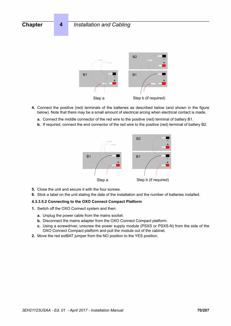
B2
B1 B1
Step a Step b (if required)
-+
-+
-+
4. Connect the positive (red) terminals of the batteries as described below (and shown in the figurebelow). Note that there may be a small amount of electrical arcing when electrical contact is made.
a. Connect the middle connector of the red wire to the positive (red) terminal of battery B1.b. If required, connect the end connector of the red wire to the positive (red) terminal of battery B2.
B2
B1 B1
Step a Step b (if required)
-+
-+
-+
5. Close the unit and secure it with the four screws.6. Stick a label on the unit stating the date of the installation and the number of batteries installed.
4.3.3.5.2 Connecting to the OXO Connect Compact Platform
1. Switch off the OXO Connect system and then:
a. Unplug the power cable from the mains socket.b. Disconnect the mains adapter from the OXO Connect Compact platform.c. Using a screwdriver, unscrew the power supply module (PSXS or PSXS-N) from the side of the
OXO Connect Compact platform and pull the module out of the cabinet.2. Move the red extBAT jumper from the NO position to the YES position.
Chapter 4 Installation and Cabling
3EH21123USAA - Ed. 01 - April 2017 - Installation Manual 70/207
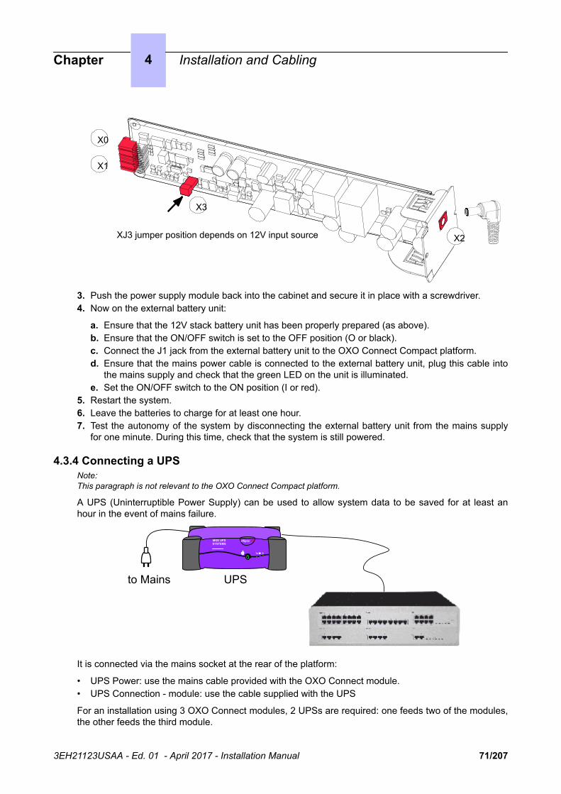
X3
X0
X1
X2XJ3 jumper position depends on 12V input source
3. Push the power supply module back into the cabinet and secure it in place with a screwdriver.4. Now on the external battery unit:
a. Ensure that the 12V stack battery unit has been properly prepared (as above).b. Ensure that the ON/OFF switch is set to the OFF position (O or black).c. Connect the J1 jack from the external battery unit to the OXO Connect Compact platform.d. Ensure that the mains power cable is connected to the external battery unit, plug this cable into
the mains supply and check that the green LED on the unit is illuminated.e. Set the ON/OFF switch to the ON position (I or red).
5. Restart the system.6. Leave the batteries to charge for at least one hour.7. Test the autonomy of the system by disconnecting the external battery unit from the mains supply
for one minute. During this time, check that the system is still powered.
4.3.4 Connecting a UPSNote:This paragraph is not relevant to the OXO Connect Compact platform.
A UPS (Uninterruptible Power Supply) can be used to allow system data to be saved for at least anhour in the event of mains failure.
MGE UPS SYSTEMS
ellipse 300
UPSto Mains
It is connected via the mains socket at the rear of the platform:
• UPS Power: use the mains cable provided with the OXO Connect module.• UPS Connection - module: use the cable supplied with the UPS
For an installation using 3 OXO Connect modules, 2 UPSs are required: one feeds two of the modules,the other feeds the third module.
Chapter 4 Installation and Cabling
3EH21123USAA - Ed. 01 - April 2017 - Installation Manual 71/207

4.3.5 Mains Connection - Ground Connection
4.3.5.1 OXO Connect Small, Medium, Large
The connection can be made using electrical installations of the following type:
• TT (local ground for each piece of equipment).• TN (common ground for all equipment).• IT with inter-phase voltage of 230 V; only possible in Norway.
Mains socket fuse: T2.5 AH / 250 V (delayed action, high cutout).
So as not to compromise the fire protection feature, replace fuses with the same type offuse having the same nominal characteristics.
For continued protection against risk of fire, replace only with same type and rating offuse.
The system is delivered with a 3 conductor cable (length: 3 m) to connect to the mains socket.
4.3.5.1.1 Permanent Ground
It is essential to connect the system permanently to ground due to leakage currents greater than 3.5mA over the whole line access (safety constraint CEI60950 ed.03). To do this, use the ground wire ofminimum section 4 mm2 provided and connect it to the tag at the rear of the unit (left hand side).
For performance and safety reasons, the system must always be connected to theground. The ground must be connected prior to all the other connections.
For performance and safety reasons, the whole system must always be coupled to theground. The ground must be connected before any other connections.
The ground protection connection terminal must always be connected to the ground.Protective grounding terminal shall be permanently connected to the ground.
4.3.5.2 OXO Connect Compact
OXO Connect Compact platform is powered by an external power supply unit (100/240V). It isconnected via a jack plug at the front of the module (right hand side).
Remarks:
- A mains cable is not supplied with the module. It must be ordered separately.
- For a more secure configuration, an AC/DC power supply, including a backup battery, can be purchased as anoptional extra.
4.3.5.2.1 Permanent Ground
It is essential to connect the system permanently to ground due to leakage currents greater than 3.5mA over the whole line access (safety constraint CEI60950 ed.03).
To do this, use the ground wire of minimum section 2.5 mm2 (not supplied) and connect it to the tag onthe metal bottom of the unit (right hand side).
For performance and safety reasons, the system must always be connected to theground. The ground must be connected prior to all the other connections.
Chapter 4 Installation and Cabling
3EH21123USAA - Ed. 01 - April 2017 - Installation Manual 72/207
For performance and safety reasons, the whole system must always be coupled to theground. The ground must be connected before any other connections.
The ground protection connection terminal must always be connected to the ground.Protective grounding terminal shall be permanently connected to the ground.
4.3.6 Power UpHaving made all the connections, it is now time to power up the system.
• Insert the mains cable in the socket on the rear of the unit.• Press the ON/OFF button. The system will reinitialize (duration: 3 to 4 minutes).
To stop the system:
• Press the ON/OFF button, the RED LED will flash.• Wait until the LED stops flashing and is lit steadily (between 15 seconds and 3 minutes depending
on the configuration): the system is switched off.
4.3.6.1 Power Up of Dedicated Terminals
On powering up, dedicated sets execute a self-test:
• Display Test• Test of the LEDs or icons on the terminal and add-on module, if any• Audio test
If this sequence is correct, the display on the dedicated terminals shows the system date: Monday 01January 00h00.
After powering up, you can activate the system from a dedicated terminal or by OMC (refer to thespecific notice).
4.4 SIP Terminals
4.4.1 8001/8001G Deskphone
4.4.1.1 8001/8001G Deskphone Commissioning4.4.1.1.1 Overview
The 8001/8001G Deskphone sets are plug&phone, which means they are automatically created in theOXO Connect, when connected to the network. A default certificate in the system allows plug&phone.
4.4.1.1.2 Prerequisites
The 8001/8001G Deskphone software must be in version 3.6.0.5. If a previous software version isinstalled on the set, the set starts as an "Open SIP Phone" and is not recognized as 8001/8001GDeskphone SIP Phone".
The software is downloaded according to the initial 8001/8001G Deskphone software version of theset:
1. Sets having a software version prior to 3.5.0.8 must be upgraded to the intermediate version 3.5.0.82. Sets are upgraded to version R120-v3.6.0.5
• The OXO Connect must be operational• A free IP address must be available for the set
Chapter 4 Installation and Cabling
3EH21123USAA - Ed. 01 - April 2017 - Installation Manual 73/207

• A port with PoE must be available on a switch• If the set is configured to start in dynamic mode (default configuration, a DHCP server must be
configured:
• If using the OXO Connect DHCP server: a range of available IP addresses must be configured(in OMC, go to ALU IP Phones: DHCP IP Range).
• If using another DHCP server: the URL for the configuration files must be provided. This URL isindicated using two proprietary options of DHCP server:
• Option 66 must specify the DM IP address, the value of this option must contain <OXOConnect_IP_address:10443>
• Sub option 67 of option 43 (DHCP Vendor Specific information) must contain a string valueset to « /dmcfg/ »
The URL to download the configuration files is https://<OXO Connect_IP_address>:10443/dmcfg.
The CGI script included in the URL is executed on the OXO Connect to create the device (ifnecessary) and generate the configuration file.
4.4.1.1.3 Connecting the set to the LAN
Once the IP configuration is done, the set can be connected to the LAN:
1. Turn the set over so that you can see its base.2. Plug the RJ45 cable into the set's LAN connector.3. Connect the RJ45 cable to the LAN.
The set starts and connects to the system
4.4.1.1.4 Connection to the system
At first appearance of the set, the system creates the configuration file associated to this set andautomatically declares the set in the system subscribers' list.
The set sends an HTTPS request to retrieve its configuration files.
Note:
The SIP parameter configuration file is named <MAC address>.xml
Example: 00809f5607ae.xml (for a set whose MAC address is 00:80:9F:56:07:AE)
The set being plug&phone, it starts automatically and can be used straight away.
The set can be further configured in OMC. It is visible in the subscribers list as SIP Phone (8001) orSIP Phone (8001G).
4.4.1.1.5 Manual (static) configuration
The set IP parameters can be modified after first initialization.
On the set itself, connected to the system:
1. Press the OK button, or the Menu softkey2. Go to System settings > Advanced settings > Advanced3. Select Network > LAN Port4. Select the Static mode5. Configure the set IP address, ensuring first that it is a free address6. Configure other IP parameters: IP subnetwork mask, and gateway (that is router)7. Configure DNS settings8. Configure port management settings9. Go to System settings > Advanced settings > Advanced > Auto Provision
Chapter 4 Installation and Cabling
3EH21123USAA - Ed. 01 - April 2017 - Installation Manual 74/207
Enter the URL: https://<OXO Connect_IP_address>:10443/dmcfg and select HTTPS asprotocol
10.Press the Save softkey
Important:If the OXO Connect is installed and configured in a VLAN topology, the VLAN must be manually enabled inthe advanced settings of the set. The corresponding OXO Connect VLAN Value must be entered manuallyin set configuration.
4.4.1.1.6 Upgrading set binaries
If requested:
1. In OMC, select Import/Export > File Management For third Party Devices2. Import the binary files and firmware configuration files in the directory named: Binary3. Reboot the set manually
When the set connects to the OXO Connect, it upgrades its software, provided the binariesimported in the system and the binaries present in the set are of a different version.
Note:Set binaries can be imported or deleted, but not exported
4.4.1.1.7 Replacing the set by another 8001/8001G Deskphone set
In case of a replacement by another 8001/8001G Deskphone set, modify the MAC address of the set inOMC.
There is no backup of terminal data, which means that the local call log and saved contacts are lost.
To replace a set initially installed as Open SIP phone by a same set and have it recognized properly bythe system:
1. Disconnect the phone from the network2. In OMC, delete the registration Open SIP Phone3. Reconnect the 8001/8001G Deskphone
It initializes normally and the OXO Connect license-bypass mechanism makes it appear as a SIP8001/8001G Deskphone.
It is preferable to disconnect 8001/8001G Deskphone set from the network during this operation. Oncereconnected, the set initializes normally and the OXO Connect license-bypass mechanism makes itappear as a SIP phone 8001/8001G Deskphone.
4.4.1.1.8 8001/8001G Deskphone password management
After a 8001/8001G Deskphone SIP Phone starts with the OXO Connect, the user password for the setweb interface is changed from the default values: root / root to admin / admin.
To configure the set, if no new administrator password has been manually entered:
• On the 8001/8001G Deskphone set : when the password is requested, do not enter anything andselect OK (or try as 000000 password)
• From the web Admin interface, enter: admin / admin
If there is a specified password, different from the default password, for a 8001/8001G Deskphone SIPphone configured in the OXO Connect, after the set is connected to the system, the login changes toadmin with the password specified in OMC System Misc/SIP Phone Admin password/SIP phone forthe phone.
If a manual 8001/8001G Deskphone SIP phone reset to factory settings is requested (for instance if theadministrator password is lost), on the set:
1. Go Menu > Functions Settings > Dial to find:
Chapter 4 Installation and Cabling
3EH21123USAA - Ed. 01 - April 2017 - Installation Manual 75/207

Set the option to "off" (no dial by name)2. With the phone idle, dial *3*3*3"
This reboots the set to factory settings
4.4.2 8082 My IC Phone
4.4.2.1 Commissioning4.4.2.1.1 Overview
This module presents all the actions required for commissioning the 8082 My IC Phone sets.
Quick Access Pad
Loudspeaker
Contextual Sensitive Touch Screen
Bluetooth Handset
Microphones
Figure 4.3: 8082 My IC Phone set layout
The following figure illustrates the connectors on the base of each set.
Chapter 4 Installation and Cabling
3EH21123USAA - Ed. 01 - April 2017 - Installation Manual 76/207

PC connector
LAN connector
Handset connector
Alphabetic keyboard connector
USB connectors
Headset jack
Additional key module connector
Power connector
Figure 4.4: 8082 My IC Phone set connectors
4.4.2.1.2 Commissioning the set
This section describes how to commission the set in the two available initialization options:
• Static initialization: commissioning is manual on the set and through OMC• Dynamic initialization (DHCP): no commissioning is needed, 8082 My IC Phone sets are fully plug &
phone
Depending on the selected mode, the set commissioning is different.
For static initialization, the operation order is as follows:
1. Connect the set, refer to Connecting the set on page 782. Configure network parameters on the set, refer to Configuring network parameters for static
initialization on page 80
For dynamic initialization, the operation order is as follows:
1. Configure OXO Connect DHCP server, refer to Configuring OXO Connect DHCP server on page79, or configure an external DHCP server, refer to Configuring an external DHCP server fordynamic initialization on page 79
2. Connect the set, refer to Connecting the set on page 783. If necessary, configure the user name and password in OMC, refer to Configuring the user name
and password in OMC on page 80
4.4.2.1.2.1 Prerequisites
• The OXO Connect must be operational
Chapter 4 Installation and Cabling
3EH21123USAA - Ed. 01 - April 2017 - Installation Manual 77/207
• For network configuration, any of the following must be implemented:
• In dynamic mode, a DHCP server must be configured• In static mode, a free IP address must be available for the set
• A port with PoE must be available on a switch. If not available, a PoE injector must be used
4.4.2.1.2.2 Connecting the set
This section describes how to:
• Connect an 8082 My IC Phone set to the LAN (Local Area Network)• Connect the external power adapter, if necessary
Note:The external power adaptor is compatible with 8082 My IC Phone HW2, it is not compatible with version HW1.
Connecting an 8082 My IC Phone set to the LAN
To connect the set to the LAN:
• If you are using the 8082 Power Over Ethernet Injector Kit:
1. Plug an RJ45 cable between the data in port of the kit and the LAN2. Plug an RJ45 cable between the data and power out port of the kit and the set LAN connector3. Plug the kit to the mains
• If you are not using the 8082 Power Over Ethernet Injector Kit, plug an RJ45 cable between the setLAN connector and a port of the switch
Connecting power supplyNote:Only available for 8082 My IC Phone HW2
If you are not using a PoE switch or the 8082 Power Over Ethernet Injector Kit, connect the AC/DCexternal adapter:
1. Plug the appropriate cable from the adapter into the set's power supply connector.2. Connect the plug from the adapter to the mains power supply.
4.4.2.1.2.3 Initializing the sets
The following sections describe how to:
• Select the initialization type• Initialize the 8082 My IC Phone set
Selecting the initialization type
The default initialization is Dynamic Alcatel.
To select the initialization type, refer to the following table.
table 4.1: Initialization type selection
If Then the required initiali-zation type is
Further information
You use OXO ConnectDHCP server
Dynamic or ProprietaryDynamic
• Refer to Configuring OXO Connect DHCPserver on page 79
You use anotherDHCP server
Dynamic • Refer to Configuring an external DHCPserver for dynamic initialization on page 79
Chapter 4 Installation and Cabling
3EH21123USAA - Ed. 01 - April 2017 - Installation Manual 78/207
You do not use aDHCP server
Static • Refer to Configuring network parameters forstatic initialization on page 80
• Obtain from your network administrator:
• An IP address for the 8082 My IC Phoneset
• The subnetwork mask• The router address• The DNS addresses (primary and
secondary)• The VLAN ID (if VLAN is used)• The IP address of the OXO Connect for
set configuration file download
Note:You need to know the set directory number.
Configuring OXO Connect DHCP server
The OXO Connect DHCP server is enabled by default during startup wizard installation. If enabled,8082 My IC Phone sets automatically initialize in dynamic mode, when plugged to the OXO Connect. Inother words, 8082 My IC Phone sets automatically get their IP configuration from the OXO ConnectDHCP server
If the OXO Connect DHCP server is disabled, you can enable it as follows:
• In OMC, go to Hardware and Limits > LAN/IP Configuration > DNS/DHCP.• In the ALU IP Phones: DHCP IP Range area, select the Enable check box.• Modify the range of IP addresses if needed.• Click the OK button to confirm your entries.
Configuring an external DHCP server for dynamic initialization
Two types of dynamic initialization are available:
• Dynamic (default value): the set selects in priority DHCP offers, with a Vendor Specific optioncorresponding to an ALE International server.
• Proprietary Dynamic: the set accepts only DHCP offers with a Vendor Specific optioncorresponding to an ALE International server (alcatel.int-ip.0, alcatel.a4400.0,alcatel.a4200.0).
When initializing in dynamic mode, the set provides the following information in the DHCP Discovermessage
• Option 60: (vendor class identifier): alcatel.ictouch.0• Option 55: list of requested options: subnet mask, router option, broadcast address, option 43
vendor specific info, server ID, renewal time, rebinding time and vendor class ID
Option 43 is vendor specific information, meaning that this option is defined for a specific client vendorID. In the DHCP offer, the data within Option 43 corresponds to the client vendor ID specified in therequest.
In the case of 8082 My IC Phone sets, suboption 67 of option 43 provides the path of configuration fileson the OXO Connect.
The DHCP offer provides the following parameters:
• IP address• Router IP address
Chapter 4 Installation and Cabling
3EH21123USAA - Ed. 01 - April 2017 - Installation Manual 79/207

• Subnet mask• Option 66: IP address:10443 or name of the OXO Connect:10443, for example
192.168.12.34:10443• Suboption 67 of option 43: the value of this sub-option corresponds to the DM Url.It must contain a
string value set to /dmcfg/• Option 58: VLAN ID: this is sent as a suboption of option 43
Optionally, the DHCP offer can include the following parameters, which can also be configured locallyon the terminal or on the OXO Connect:
• Option 6: Domain Name Server (DNS primary and secondary)• Option 15: Domain name• Option 12: Host name (eg, ICTouch<MAC>)• Option 42: SNTP server• Option 120: SIP server (outbound proxy server address or name)
Configuring network parameters for static initialization
MMI allows to access and configure the following parameters (you must have administration rights tomodify static configuration):
• In the Network menu:
• DM (OXO Connect) URL: https://OXO Connect IP address:10443/dmcfg/• DNS addresses• Ethernet parameters: the LAN and PC Ethernet interfaces are by default configured in auto-
negotiation mode• IP parameters• Log parameters, allowing to define a syslog server for log reception• Network parameters, allowing to:
• Enable and configure a DHCP User Class: this makes the set send the standard DHCPoption 77 (User Class, RFC2132) within the DISCOVER and REQUEST DHCP messages.Using this option allows to define groups of terminals, and to attach these groups to differentand independent Com Servers.
• Define an SNTP Server address and refresh period• Proxy host and port• SIP parameters (read only)
• In Security menu:
• 802.1x parameters• Certificates: not used
4.4.2.1.2.4 Configuring the user name and password in OMC
The user default password for a new user is defined at first installation. If need be, the administratorcan reset the user default password via the OMC
To modify the name and reset the password:
• In OMC, go to Users/Base stations List.• To modify the user name: click the user in the list, modify the user name in the corresponding field
and click Modify• To reset the user password:
• Click the user in the list and click Details to open the User window• Click Password to open the Password window• Click Reset to reset the password
Chapter 4 Installation and Cabling
3EH21123USAA - Ed. 01 - April 2017 - Installation Manual 80/207

Note:At reset, the password is set to the user default password value defined at first intallation.
4.4.2.1.2.5 Voice mail access
Using the IcsMessaging Web Service, a voice communication is automatically established between the8082 My IC Phone set and the VMU to:
• Manage the messages (play, pause, stop)• Delete one or all messages• Record, send or cancel a new message
A VMU password can be required to access the voice mailbox from the local voice mail application.The IcsUserProfile Web Service is used for password verification.
Note:Password authentication is only requested when the parameter is validated
To validate password requirement:
In OMC:
1. Select Voice Processing2. Select General Parameters3. Verify Password required for mailbox consultation
4.4.2.1.2.6 Connecting optional equipmentHeadsets
A headset can be used with 8082 My IC Phone sets.
By default the set is configured to detect headset connection. When the headset is plugged in, theaudio is sent to the headset. The hands-free key allows you to switch from handset, headset andhands-free.
A Bluetooth® headset may be used.
If your headset is wired, plug it to the associated set connector (see: Figure 2), which can be any of thefollowing:
• The jack plug• The set USB port
External station speakers
Any connector used for a headset can be used for external speakers.
Customize your set to take the external station speaker into account:
1. Touch the Settings button
Note:According to system administration, this button may not appear. The availability of this option is determined bythe set configuration files. Contact your telephony and/or system administrator.
2. Select Devices > Audio3. Select the connection of your choice (from Accessory device to Bluetooth® device)4. Touch the field to access available values5. Select Loudspeaker6. If your device is not Bluetooth®, plug it to the corresponding connector
Traffic priority on the internal switch
The 8082 My IC Phone set includes an internal LAN switch.
This switch allows to connect a PC.
Chapter 4 Installation and Cabling
3EH21123USAA - Ed. 01 - April 2017 - Installation Manual 81/207

The internal switch has three ports:
• A LAN port• An internal port• A PC port, to connect a PC to the LAN.
The internal switch privileges VoIP traffic over PC port traffic.
This switch has two waiting queues:
• The HPQ (High Priority Queue) to proceed all packets from the terminal• The LPQ (Low Priority Queue) to proceed packets from the PC port
The switch proceeds seven HPQ packets for an LPQ packet.
Exception: packets from the PC port use the HPQ when they are tagged with a DSCP or 802.1p priorityand when the priority value is superior or equal to 4.
4.4.2.1.2.7 Resetting user data
To reset user data:
1. In OMC, go to Users/Base stations List > Details.2. Click Reset.
The Reset window opens.3. Select Reset User Data and click OK.4. In the confirmation window, click Yes.
4.4.2.1.2.8 Rebooting an 8082 My IC Phone set
To reboot a set:
1. In OMC, go to Users/Base stations List > Details.2. Click Reset button.
The Reset window opens.3. Select Reboot and click OK.4. In the confirmation window, click Yes.
4.4.2.1.2.9 Displaying SIP connection current status
This feature allows the display of SIP connection status.
To display SIP connection status:
1. In OMC, go to Users/Base stations List > Details.2. Read the SIP connection status (under the terminal's physical status).
The following table lists the different displayed status.
table 4.2: SIP connection status display
Displayed Status Meaning
Set not connected SIP phone disconnected from network / No SIPregistration request from the phone
SIP registration KO SIP registration request from SIP Phone rejec-ted by OXO Connect
Set unregistered SIP phone unregistered from OXO Connect
Chapter 4 Installation and Cabling
3EH21123USAA - Ed. 01 - April 2017 - Installation Manual 82/207

SIP registration OK SIP phone connected and successfully regis-tered to OXO Connect
4.4.2.1.2.10 Terminal conference
8082 My IC Phone sets can handle their own local conference, involving up to 2 external members. Inthis case, conference is not handled at call server level and the Conference parameter configured inSystem Miscellaneous > Feature Design > Part 3 does not apply.
4.4.2.1.3 Ringing parameters
The set user can select different ringing tones for the different types of call or event.
To configure ringing tones:
1. Touch the Settings button
Note:According to system administration, this button may not appear. The availability of this option is determined bythe set configuration files. Contact your telephony and/or system administrator.
2. Select Devices > Audio3. Review/modify the following parameters:
On-site ringing Select the ringing for external calls
Off-site ringing Select the ringing for internal calls
Event ringing Select the ringing for calendar events
Special ringing Select the ringing indicating that the Bluetooth® handset is out of range
4.4.2.1.4 Video call parameters
The OmniPCX Management Console (OMC) is used to enable the video call support for the 8082 MyIC Phone sets. Once configured it is possible to make:
• Basic P2P video calls between 8082 My IC Phone (VHE-2) and any SIP phone with video support.• Basic video calls from 8082 My IC Phone (VHE-2) over a SIP trunk
The configuration for video is carried out in two steps:
1. Generic SIP phone parameters for video calls are verified and modified if necessary, see Genericvideo parameters on page 83
2. Each set is enabled, see Enabling video support for a 8082 My IC Phone set on page 85
4.4.2.1.4.1 Generic video parameters
The parameters in the table are generic (common) to all 8082 My IC Phone sets. They are accessedfrom:
OMC -> Subscribers Misc -> Generic Parameters for SIP Phones -> Video Call parameters
Video Camera Country Frequency: defines the vertical scan frequency which is needed to avoidflickering of video. This is same as the mains power frequency of the country. Default value for thisparameter is kept based on the target type (country) of the OXO Connect.
Chapter 4 Installation and Cabling
3EH21123USAA - Ed. 01 - April 2017 - Installation Manual 83/207

Country Type Video Camera Country Fre-quency (Default value in OMC)
Brazil Costa-Rica Guatemala Haiti Honduras Mexico PanamaPhilippines Saudi Arabia Taiwan USA Venezuela Verizon
60 Hz
All others 50 Hz
Video Camera Refresh Cycle: defines the time interval between two full pictures refresh in seconds.This parameter impacts the network bandwidth usage.If the value of this parameter is 0, it indicates norefresh.
Video Differential Services: indicates the value of ‘Differential Services’ field in the IP header.
Video 802.1p: indicates the value of ‘802.1p’ field in the IP header.
Video Call Profile Level ID: indicates the value of ‘SDP’ field in IP header. This parameter encodes init, the information on profile, level and ID for video call encoding.
Video Call Encoding Profile: defines the profile that 8082 My IC Phone must use for video streamencoding. This impacts the quality of the video.
Video Encoding Profile Low/Medium/High: defines the bandwidth used for low/Medium/High levelvideo encoding profile in kbps.
Video Call Packetization Mode: defines packetization mode (PM) among 3 values:
PM1 provides best quality video with reduced bandwidth. If the distant set does not support PM1, PM0is used. PM0 should be avoided since it is not well supported on 8082 My IC Phone. NS is forexclusive use of PM1. If NS is not supported by the distant, negotiation fails (no video)
All the video configuration parameters and their possible values are described in Table 3
table 4.3: Video parameters
OMC Parameter Common/Specificto 8082 My ICphones
Default Value Possible Values
Video Support Specific to Terminal Enabled Enabled/Disabled
Video Camera Country Frequency Common Based on targetcountry
50 Hz / 60 Hz
Video Camera Refresh Cycle Common 2 [0 .. 2160]
Video Differential Services Common 5 [ 0 .. 63 ]
Video 802.1p Common 5 [0 .. 7]
Video Call Profile Level ID Common 0x42801E [0...0xFFFFFF]
Video Call Encoding Profile Common Medium Low/Medium/High
Video Encoding Profile Low Common 256 kbps 0 .. 65535]
Chapter 4 Installation and Cabling
3EH21123USAA - Ed. 01 - April 2017 - Installation Manual 84/207

OMC Parameter Common/Specificto 8082 My ICphones
Default Value Possible Values
Video Encoding Profile Medium Common 1000 kbps [0 .. 65535]
Video Encoding Profile High Common 2500 kbps [0 .. 65535]
Video Call Packetization Mode Common PM0 PM0 / PM1 / NS
4.4.2.1.4.2 Enabling video support for a 8082 My IC Phone set
The Video Support feature right is specific to each 8082 My IC Phone set. Video telephony is enabledor disabled specifically for each set.
Note:Enabling is mandatory to support Video calls (incoming or outgoing) for 8082 My IC Phone sets.
To enable/disable “Video Support”
OMC -> User/Base stations List -> 8082 MY IC Phone-> Details-> Features -> Feature Rights ->Part 1
Video support: select the check box to allow video support on the 8082 My IC Phone.
4.4.2.1.5 SIP door phone parametersNote:If SIP door phone management is to be done with video support, refer to Video call parameters on page 83 toenable video.
The generic parameters for SIP door phone management with 8082 My IC Phone can be modified at
OMC -> Subscribers Misc -> Generic Parameters for SIP Phones -> Door Phone Parameters
OMC Parameter Common/Specific to8082 My IC phones
Default Value Possible Values
Door Phone Name Common Doorcam STRING
Door Open Signal Common 55 STRING
Door Phone Name: defines the name that must be given for all SIP door phone terminals. Defaultvalue for this parameter is 'Doorcam'.
The unique name defined with ‘Door Phone Name’ parameter is used by 8082 My IC Phone to identifycalls from SIP door phones.
Note:The 'Door Phone Name’ parameter is case sensitive. SIP door phone names must be unique and not the same asthe ‘Door Phone Name’ parameter.
Door Open Signal: defines the DTMF code that is sent from 8082 My IC Phone to SIP door phone toopen the door latch. The default value for this parameter is 55.
4.4.2.1.6 Upgrading the software
The Alcatel-Lucent OmniTouch™ 8082 My IC Phone set software is upgraded during OXO Connectsoftware upgrade. Ensure the 8082 My IC Phone option is validated in the OMC-Software Downloadwindow: refer to the section Downloading the Software in document [11].
Chapter 4 Installation and Cabling
3EH21123USAA - Ed. 01 - April 2017 - Installation Manual 85/207

4.4.2.2 Reset to factory4.4.2.2.1 Overview
The reset to factory is intended to cope with situations in which the administrator can no longer accessthe set configuration because the set administrator password has been lost, and the set is configuredin static mode or uses a specific VLAN on the previous installation. Reset to factory is not neededwhen a set is configured in dynamic mode: in this case, the set administrator password can bechanged through the device management tool.
The reset to factory enables to restore the set to the “Out of the box” initial status, except that thesoftware version remains unchanged on the set. It works during the set initialization. If initialization isdone, there is no other solution to reset sets to their factory settings.
The reset to factory performs the following actions:
• Restore the set administrator password to its default value• Clean all user data and webapps• Restore the configuration and settings to their default values• Remove certificate data such as customer certificates and CTL, except ALE International default
certificate stored during manufacturing• Store a message into Defense log to indicate a reset-to-factory has been done• Reboot
Note:
Although the feature is not intended for end-users, it is available in user mode, as this feature is used when the setadministrator password has been lost, and therefore the administrator mode cannot be reached.
It is not possible to limit the availability of the feature for users and/or administrators by setting the appropriatedisplay-rights to the setting EnableResetFactory in the third configuration files, generated by theCustomizer.
4.4.2.2.2 Procedure
To perform the reset to factory on a set:
1. Restart the set2. During set initialization (step 2 or 3), press Settings3. Select Device > Reset
4. Set the Reset to factory option to Yes
Your are prompted to enter the administrator password required for the reset to factory.
The default administrator password is *tx8000#.
Chapter 4 Installation and Cabling
3EH21123USAA - Ed. 01 - April 2017 - Installation Manual 86/207

5. Enter the administrator password, then press OK to confirm the reset to factory, or press Cancel tocancel the reset.
• If the password is WRONG or Cancel is pressed; the set displays again the reset screen, thechoice selector is set to NO: without further action, the set will go on with normal startup.
• If the password is VALID, you are prompted to confirm the action:
6. Press Yes to confirm the reset to factory: reset to factory is performed and the set restartsimmediately.
Press No to cancel: the set displays again the reset screen, the choice selector is set to NO: withoutfurther action, the set will go on with normal startup.
4.4.3 4135 IP Conference Phone
4.4.3.1 Commissioning4.4.3.1.1 Overview
This module presents all the actions required for commissioning 4135 IP Conference Phone sets.
Chapter 4 Installation and Cabling
3EH21123USAA - Ed. 01 - April 2017 - Installation Manual 87/207

Figure 4.5: 4135 IP Conference Phone set layout
The following figure illustrates the connectors on the base of each set.
Chapter 4 Installation and Cabling
3EH21123USAA - Ed. 01 - April 2017 - Installation Manual 88/207

Figure 4.6: 4135 IP Conference Phone set connectors
The 4135 IP Conference Phone is a SIP device which has no handset; it is dedicated to be used ascentral for conferences.
Conferences are not managed by the system, but by the device itself. Up to four 4135 IP ConferencePhones can be connected to the OXO Connect.
4.4.3.1.2 Commissioning the set
This section describes how to commission the set in the two available commissioning types:
• Static: commissioning is manual on the set and on OMC• Dynamic (DHCP): the set automatically retrieves its IP address and other parameters from a DHCP
server (OXO Connect DHCP server or an external DHCP server) . Complementary operations arenecessary on the set and on OMC
For static commissioning, operations are:
1. Configure the user in OMC, refer to Configuring the user by OMC on page 902. Connect the set to the LAN, refer to Connecting the set to the LAN on page 903. Configure the network parameters on the set, refer to Configuring network parameters for static
initialization on page 924. Export the server certificate from the OXO Connect: refer to Exporting the server certificate from the
OXO Connect on page 925. Upload the certificate on the 4135 IP Conference Phone
For dynamic commissioning, operations are:
1. Configure OXO Connect DHCP server, refer to Configuring OXO Connect DHCP server on page91, or configure an external DHCP server, refer to Configuring an external DHCP server on page91
2. Connect the set to the LAN, refer to Connecting the set to the LAN on page 90
Chapter 4 Installation and Cabling
3EH21123USAA - Ed. 01 - April 2017 - Installation Manual 89/207

3. Configure the user name and password and consult the SIP password in OMC, refer to Configuringthe user name and password in OMC on page 92
4. Export the server certificate from the OXO Connect: refer to Exporting the server certificate from theOXO Connect on page 92
5. Enter the SIP password through MMI, refer to Entering the SIP password through local MMI onpage 93
6. Upload the certificate on the 4135 IP Conference Phone
4.4.3.1.2.1 Prerequisites
• The OXO Connect must be operational• For network configuration, any of the following must be implemented:
• In dynamic mode, a DHCP server must be configured• In static mode, a free IP address must be available for the set
• A port with PoE must be available on a switch
4.4.3.1.2.2 Configuring the user by OMC
This paragraph applies to OMC configuration of sets initializing in static mode. In dynamic (DHCP)mode, the following operation is not mandatory but the server certificate must be exported from theOXO Connect to the PC and can then be uploaded to the 4135 IP Conference Phone.
To create a 4135 IP Conference Phone:
1. In OMC, go to Users/Base stations List.2. Select a No., IP access, enter a name and click the Add button.3. Select IP terminal and click OK.4. Select the newly created user in the list and select 4135 IP Conference Phone in the combo box
type.5. Click the Modify button.6. Click the newly created user to open the User dialog box.7. Click the IP/SIP button and enter the MAC adress of the set in the IP Parameters tab.8. If needed, in the SIP Parameters, click the SIP password reset button to get a new password.
4.4.3.1.2.3 Connecting the set to the LANNote:the set is supplied via Ethernet, so make sure using a 802.3af standard-compatible switch.
To connect the set to the LAN:
1. Turn the set over so that you can see its base.2. Plug the RJ45 cable into the set's LAN connector.3. Connect the RJ45 cable to the LAN.
4.4.3.1.2.4 Initializing the sets
This section describes how to:
• Select the initialization mode• Initialize the 4135 IP Conference Phone set
Selecting the initialization type
The default initialization is Dynamic Alcatel.
To select the initialization type, refer to the table below.
Chapter 4 Installation and Cabling
3EH21123USAA - Ed. 01 - April 2017 - Installation Manual 90/207

table 4.4: Initialization type selection
If Then the required initiali-zation mode is
Further information
You use OXO ConnectDHCP server
Dynamic or ProprietaryDynamic
• Refer to Configuring OXO Connect DHCPserver on page 91
You use anotherDHCP server
Dynamic • Refer to Configuring an external DHCPserver on page 91
You do not use aDHCP server
Static • Refer to Configuring network parameters forstatic initialization on page 92
• Obtain from your network administrator:
• An IP address for the 4135 IP ConferencePhone set
• The subnetwork mask• The router address• The DNS addresses (primary ans
secondary)• The VLAN ID (if VLAN is used)• The IP address of the OXO Connect for
configuration files download
Note:You need to know the set directory number.
Configuring OXO Connect DHCP server
The OXO Connect DHCP server is enabled by default during startup wizard installation. If enabled,4135 IP Conference Phone sets automatically initialize in dynamic mode, when plugged to the OXOConnect. In other words, 4135 IP Conference Phone automatically get their IP configuration from theOXO Connect DHCP server.
If the OXO Connect DHCP server disabled, you can enable it as follows:
• In OMC, go to Hardware and Limits > LAN/IP Configuration > DNS/DHCP.• In the ALU IP Phones: DHCP IP Range area, select the Enable check box.• Modify the range of IP addresses if needed.• Click the OK button to confirm your entries.
Configuring an external DHCP server
In Dynamic initialization (default value), the set selects the first DHCP offer, with a Vendor Specificoption corresponding to an Alcatel-Lucent server.
When initializing in dynamic mode, the set provides the following information in the DHCP Discovermessage:
• Option 60: (vendor class identifier): alcatel.sip.0• Option 55: list of requested options: subnet mask, router option, broadcast address, option 43
vendor specific info, server ID, renewal time, rebinding time and vendor class ID
Option 43 is vendor specific information, meaning that this option is defined for a specific client vendorID. In the DHCP offer, the data within Option 43 corresponds to the client vendor ID specified in therequest.
Chapter 4 Installation and Cabling
3EH21123USAA - Ed. 01 - April 2017 - Installation Manual 91/207

In the case of 4135 IP Conference Phone sets, suboption 67 of option 43 provides the path ofconfiguration files on the ALE International.
The DHCP offer provides the following parameters:
• IP address• Router IP address• Subnet mask• Option 66: IP address or name of the OXO Connect:10443, for example 192.168.12.34:10443• Suboption 67 of option 43: the value of this sub-option must contain a string value set to https://
alize/dmcfg/• Option 58: VLAN ID: this is sent as a suboption of option 43
Optionally, the DHCP offer can include the following parameters, which can also be configured locallyon the terminal or on the OXO Connect:
• Option 6: Domain Name Server (DNS primary and secondary)• Option 15: Domain name• Option 12: Host name (eg, ICTouch<MAC>)• Option 42: SNTP server• Option 120: SIP server (outbound proxy server address or name)
Exporting the server certificate from the OXO Connect
1. Go to OMC->Import/Export->Export Server Certificate.
The Export Server Certificate window is displayed2. Click Browse button.
The Exportfile window is displayed:
• The File name field indicates server.crt. The file name can be modified as needed• The Files of type field indicates Certificate Files
3. Specify the destination path for the export and click OK: The selected path and the certificate filename are displayed in the Export Server Certificate window
4. Click the Export button: The certificate file is exported from the OXO Connect to the specified filepath in PC
5. Click the Return button
Configuring network parameters for static initialization
The following parameters must be entered through the MMI:
• IP address• Subnet mask• Gateway address• DNS addresses• VLAN use• VLAN ID (if VLAN use is set)• URL: provides the URL on the OXO Connect to download configuration file. The path on the OXO
Connect is /dmcfg/• SIP password
4.4.3.1.2.5 Configuring the user name and password in OMC
To modify the name and password:
• In OMC, go to Users/Base stations List.• Click the user in the list.
Chapter 4 Installation and Cabling
3EH21123USAA - Ed. 01 - April 2017 - Installation Manual 92/207

• Modify the user name in the corresponding field and click Modify.• Double-click the user in the list to open the User dialog box.• Click on IP/SIP, go to SIP parameters tab to consult the SIP password.
4.4.3.1.2.6 Displaying SIP Connection Current Status
This feature allows the display of SIP connection status.
To display SIP connection status:
1. In OMC, go to Users/Base stations List > Details.2. Read the SIP connection status (under the terminal's physical status).
The following table lists the different displayed status.
Displayed Status Meaning
Set not connected SIP phone disconnected from network / No SIPregistration request from the phone
SIP registration KO SIP registration request from SIP Phone rejec-ted by OXO Connect
Set unregistered SIP phone unregistered from OXO Connect
SIP registration OK SIP phone connected and successfully regis-tered to OXO Connect
4.4.3.1.2.7 Entering the SIP password through local MMI
For static and dynamic initialization, enter the SIP password through MMI.
4.4.3.1.3 Upgrading the software
The 4135 IP Conference Phone set software is automatically upgraded during OXO Connect softwareupgrade (there is no specific option to select in the OMC-Software Download window: refer to thesection Downloading the Software in document [11]).
The 4135 IP Conference Phone set software can also be upgraded manually through the MMI.
4.4.4 Generic SIP Phones
4.4.4.1 Commissioning4.4.4.1.1 Overview
This module presents all the actions required for commissioning generic SIP sets.
The List of supported SIP Phones is available on the Alcatel-Lucent Applications Partner Program(AAPP) web site.
4.4.4.1.2 Commissioning Generic SIP Sets
This section describes how to commission a generic SIP Set.
The following operations must be performed:
1. Configure the user in OMC, refer to Configuring the User in OMC on page 942. Connect the set, refer to Connecting the Set on page 94 and switch it on3. Configure the generic SIP set, refer to Configuring the generic SIP set on page 94, or configure the
OXO Connect DHCP server, refer to Configuring OXO Connect DHCP server on page 95.
Chapter 4 Installation and Cabling
3EH21123USAA - Ed. 01 - April 2017 - Installation Manual 93/207

4.4.4.1.2.1 Prerequisites
• The OXO Connect must be operational• A free IP address must be available for the set• A port with PoE must be available on a switch
4.4.4.1.2.2 Configuring the User in OMC
To create a generic SIP set:
1. In OMC, go to Users/Base stations List.2. Select a No., IP access and click on the Add button.3. Select IP terminal and enter a Name.4. Select the newly created user in the list and select Basic SIP Phone or Open SIP Phone in the
combo box.
See the different features relating to basic or open SIP modes: section Services offered on SIPand DECT (IP-DECT) sets in document [3].
5. Click the Modify button.6. Click the Details button. The User window is opened.7. Click the IP/SIP button. The IP/SIP parameters window is opened.8. In the SIP parameters tab, click the SIP password reset button. A new password is generated in
the SIP password field.9. A virtual MAC Address is automatically generated but it can be replaced by the real MAC Address
of the SIP device.
Note:The MAC Address must be unique and is used to identify the subscriber in the OXO Connect call handling (SIPpassword is used for authentication).
10.Note this new password safely. It will be requested during the generic SIP set configuration(Configuring the generic SIP set on page 94).
4.4.4.1.2.3 Connecting the Set
This section describes how to:
• Connect a generic SIP set to the LAN (Local Area Network)• Connect the power supply
Prerequisites
None
Connecting a SIP set to the LANNote:If the set is supplied via Ethernet, ensure you are using a 802.3af standard-compatible switch.
To connect the set to the LAN:
• Plug the RJ45 cable into the set's LAN connector.• Connect the RJ45 cable to the LAN.
Connecting Power Supply (Optional)
To supply power via an AC/DC external adapter:
• Plug the appropriate cable from the adapter into the set's power supply connector.• Connect the plug from the adapter to the mains power supply.
4.4.4.1.2.4 Configuring the generic SIP set
The following parameters must be entered through the MMI or web interface when available:
Chapter 4 Installation and Cabling
3EH21123USAA - Ed. 01 - April 2017 - Installation Manual 94/207

• IP address (if no DHCP server is configured)• Subnet mask (if no DHCP server is configured)• Gateway adress (if no DHCP server is configured)• DNS adresses (if no DHCP server is configured)• VLAN use (if no DHCP server is configured)• VLAN ID if VLAN use is set (if no DHCP server is configured)• SIP username• SIP password: this is different from the user password. It is randomly generated for each SIP
phone by the system and must be provided to the user in a secured way. It is used both for SIPregistration and for SIP authentication, since every SIP message must be authenticated.
Note:
The random password must be entered manually in MMI. It must be made of with letters and numbers only andcan be viewed/reset in OMC.
This password has been previously generated in: Configuring the User in OMC on page 94.• SIP Phone Signal Source Port: default value is 5059. This value can be modified to any valid free
port.• Registrar and proxy IP addresses: the OXO Connect IP address and the SIP port must be set to
value 5059• Authentication Realm: OXO Connect IP address by default• Registration interval: value greater than 120 seconds• Transport protocol: the UDP protocol is preferred, TCP is used if the SIP packet length is greater
than the MTU value or if the remote SIP endpoint requests the TCP protocol• Domain name: OXO Connect IP address by default
4.4.4.1.2.5 Configuring OXO Connect DHCP server
Generic SIP phones can use the OXO Connect DHCP server.
By default the OXO Connect DHCP server is not activated for generic SIP phones.
To activate the OXO Connect DHCP server:
1. In OMC, go to Hardware and Limits > LAN/IP Configuration > DNS/DHCP2. In the Advanced DHCP IP range area, select the Enable check box.3. Define the range of IP addresses ( Start IP address and End IP Address).4. Click the OK button to confirm your entries.
For DHCP advanced configuration, refer to the section DHCP configuration in document [14].
4.4.4.1.2.6 Displaying SIP Connection Current Status
This feature allows the display of SIP connection status.
To display SIP connection status:
1. In OMC, go to Users/Base stations List > Details.2. Read the SIP connection status (under the terminal's physical status).
The following table lists the different displayed status.
Displayed Status Meaning
Set not connected SIP phone disconnected from network / No SIPregistration request from the phone
Chapter 4 Installation and Cabling
3EH21123USAA - Ed. 01 - April 2017 - Installation Manual 95/207
SIP registration KO SIP registration request from SIP Phone rejec-ted by OXO Connect
Set unregistered SIP phone unregistered from OXO Connect
SIP registration OK SIP phone connected and successfully regis-tered to OXO Connect
4.5 8018 DeskPhone
4.5.1 Commissioning
4.5.1.1 Connecting the set
To connect the set to the PBX:
1. Plug the RJ45 cable into the set LAN connector2. Connect the RJ45 cable to the LAN itself3. If your set is not powered by PoE, plug the AC/DC external adapter to the set power supply
connector and connect the plug to the power supply
Once the set is connected and powered up, it automatically starts initializing.
4.5.1.2 Set initialization
By default, 8018 DeskPhone sets initialize dynamically and retrieve IP information automatically.
You can change this initialization mode. Static initialization is mandatory when the system does not usea DHCP server.
To switch from dynamic initialization to static initialization and modify IP parameters:
1. Wait for the set to initialize and reach the end of the Network setup process, displayed on screen2. Press simultaneously the star and pound keys
This displays IP settings3. Use the soft key next to an option to modify the selection4. Validate your modifications with the soft key next to the tick symbol
4.5.1.2.1 Requested IP parameters
The following information must be provided for static initialization:
• IP address (set's address)• Subnetwork mask• Router address• TFTP1 server address: OXO Connect IP address• Use VLAN: this box must be checked to enter a VLAN number• VLAN number if necessary• TFTP port
The TFTP address(es) to enter may differ according to system configuration.
Please contact your system administrator for details on the configuration of your system.
With dynamic initialization, IP parameters are automatically sent by a DHCP server to the phone.
Chapter 4 Installation and Cabling
3EH21123USAA - Ed. 01 - April 2017 - Installation Manual 96/207

4.5.1.2.2 Deny of download
If the downloaded version is different from the version installed on the set and if the downloaded binaryis incompatible with the hardware/software, the terminal denies it and signals the problem to theCommunication Server.
The terminal requests binary files at each reset until a compatible binary is found.
Deny of download also applies to SIP binary.
4.5.1.3 Binary file download
On 8018 DeskPhone sets, binary upgrade is silent and takes place in the background, once the OXOConnect has detected that an upgrade is required. Once the file is downloaded by the set and whenthe terminal is idle, it resets and implements the new software.
While downloading the new firmware, the set runs with the current firmware.
4.6 8028/8038/8068 Premium DeskPhones
4.6.1 Commissioning
4.6.1.1 Connecting the set
To connect the set to the PBX:
1. Plug the RJ45 cable into the set LAN connector2. Connect the RJ45 cable to the LAN itself3. If your set is not powered by PoE, plug the AC/DC external adapter to the set power supply
connector and connect the plug to the power supply
Once the set is connected and powered up, it automatically starts initializing.
4.6.1.2 Commissioning a Bluetooth® handset
The use of the 8068 Premium DeskPhone with Bluetooth or without Bluetooth can be detected (inOMC, Expert View): Subscribers/Basestations list > Device details > Susbscriber tab) as follows:
• For a 8068 Premium DeskPhone with Bluetooth set: the Terminal option “8068 PremiumDeskPhone” is displayed in Original Type field.
In this deskphone type, bluetooth option is available in the phone menu (Settings > My Phone)• For a 8068 Premium DeskPhone without Bluetooth set: the Terminal option ”8068 Premium
DeskPhone – no BT” is displayed in Original Type field.
In this deskphone type, bluetooth option is not available in the phone menu.
Caution:Bluetooth handsets are available for 8068 Premium DeskPhone with Bluetooth sets only. The handset withreference BTHS-2 is compatible with 8068 Premium DeskPhone with Bluetooth sets.
Chapter 4 Installation and Cabling
3EH21123USAA - Ed. 01 - April 2017 - Installation Manual 97/207
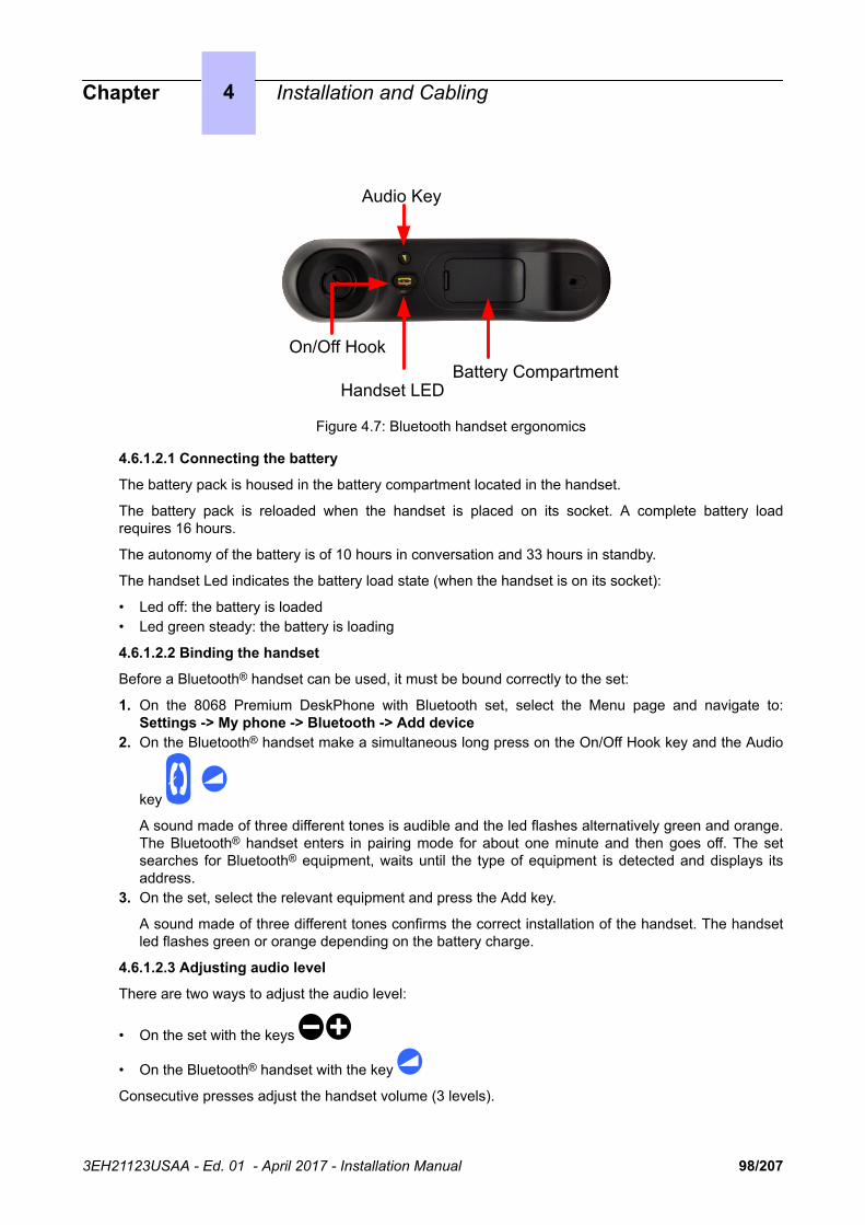
Battery CompartmentHandset LED
On/Off Hook
Audio Key
Figure 4.7: Bluetooth handset ergonomics
4.6.1.2.1 Connecting the battery
The battery pack is housed in the battery compartment located in the handset.
The battery pack is reloaded when the handset is placed on its socket. A complete battery loadrequires 16 hours.
The autonomy of the battery is of 10 hours in conversation and 33 hours in standby.
The handset Led indicates the battery load state (when the handset is on its socket):
• Led off: the battery is loaded• Led green steady: the battery is loading
4.6.1.2.2 Binding the handset
Before a Bluetooth® handset can be used, it must be bound correctly to the set:
1. On the 8068 Premium DeskPhone with Bluetooth set, select the Menu page and navigate to:Settings -> My phone -> Bluetooth -> Add device
2. On the Bluetooth® handset make a simultaneous long press on the On/Off Hook key and the Audio
key
A sound made of three different tones is audible and the led flashes alternatively green and orange.The Bluetooth® handset enters in pairing mode for about one minute and then goes off. The setsearches for Bluetooth® equipment, waits until the type of equipment is detected and displays itsaddress.
3. On the set, select the relevant equipment and press the Add key.
A sound made of three different tones confirms the correct installation of the handset. The handsetled flashes green or orange depending on the battery charge.
4.6.1.2.3 Adjusting audio level
There are two ways to adjust the audio level:
• On the set with the keys
• On the Bluetooth® handset with the key
Consecutive presses adjust the handset volume (3 levels).
Chapter 4 Installation and Cabling
3EH21123USAA - Ed. 01 - April 2017 - Installation Manual 98/207

4.6.1.2.4 Activating the mute feature
When the mute feature is enabled your correspondent can no longer hear you.
There are two ways to activate the mute feature:
• On the set with the mute key
• On the Bluetooth® handset with a long press on the key
4.6.1.3 Connecting an add-on module to the sets
Add-On Modules (AOMs) can be connected to sets. They are added to the right side of the set.
Three types of Add-On Module exist and provide keys associated with icons:
• AOM10 provides 10 keys• AOM40 provides 40 keys• Smart Display Module provides 14 keys with programmable LCD labels
4.6.1.3.1 Rules and restrictions
The following rules apply to the use of Add-On Modules:
• A maximum of three Add-On Modules of the types AOM10 and AOM40 can be connected to eachset, providing up to 120 additional keys.
• A maximum of three Smart Display Modules can be connected to each set, providing up to 42additional keys.
• Add-On Modules of types AOM10 and AOM40 can be used on the same set, but a Smart DisplayModule cannot be used in conjunction with an AOM10 or AOM40.
• If an AOM10 is used with other Add-On Modules, it must be connected as the last module on the farright of the set.
4.6.1.3.2 Connecting add-on modules
To connect an Add-On Module:
1. Remove the tab located on the right side of the set.2. Plug the Add-On Module's SATA connector into the set's SATA connector.3. Insert the Add-On Module attachments into the appropriate holes located on the right side of the
set. (AOM10 only)4. Screw the Add-On Module to the set. (AOM10 only)
Note:If the set is on when you plug in an Add-On Module, you must restart the set after connection.
4.6.1.4 Set initialization
By default, 80x8 sets initialize dynamically and retrieve IP information automatically.
If you want to change initialization mode or configure IP settings:
1. Press the i key and the # key simultaneously when the set is powered up2. Enter your password (if needed) and validate
The configuration menu is displayed3. Get to IP parameters4. Click on the icon on the left to validate (or on the icon on the right to cancel)5. Reset the phone to validate your modifications
Static initialization is mandatory when the system does not use a DHCP server.
Chapter 4 Installation and Cabling
3EH21123USAA - Ed. 01 - April 2017 - Installation Manual 99/207

If the sets must initialize dynamically, the auto provisioning must be activated: see Security - Autoprovisioning
4.6.1.4.1 Requested IP parameters
The following information must be provided for static initialization:
• IP address (set's address)• Subnetwork mask• Router address• TFTP1 server address (parameter not used)• TFTP2 server address (parameter not used)• Use VLAN: this box must be checked to enter a VLAN number• VLAN number if necessary• Strict VLAN if necessary• TFTP port
With dynamic initialization, IP parameters are automatically sent by a DHCP server to the phone.
The following information must be provided for initial startup:
1. From the Registration window, enter:
a. The set directory numberb. The set Password
If the set has already been initialized in the same configuration, there is no need to enter the directorynumber and password again.
4.6.1.4.2 Deny of download
If the downloaded version is different from the version installed on the set and if the downloaded binaryis incompatible with the hardware/software, the terminal denies it and signals the problem to the CallServer.
The terminal requests binary files at each reset until a compatible binary is found.
Deny of download also applies to SIP binary.
4.6.1.5 Binary file download
To operate correctly, 80x8 sets require binary files, automatically downloaded at set initialization. Thesefiles must comply with the PBX version and configuration. After system upgrade and each time a setinitializes, version numbers of binary files are verified to determine whether an update of these files isnecessary.
When a file is downloaded to the set, it overwrites any previously existing file.
Each time the IP phone is initialized, its binary version is checked to see whether more recent binariesneed downloading.
When a set has initialized at least once with the PBX, on subsequent startup, it does not request abinary header and switches to fast initialization.
The version of binary files for Premium DeskPhone sets. starts with 4.50.YY
Chapter 4 Installation and Cabling
3EH21123USAA - Ed. 01 - April 2017 - Installation Manual 100/207

4.7 Alcatel-Lucent IP Touch 4018 phone Extended Edition
4.7.1 Commissioning
4.7.1.1 Overview
This module presents all the actions required for commissioning the Alcatel-Lucent IP Touch 4018phone Extended Edition set.
The following figure illustrates the connectors on the base of the Alcatel-Lucent IP Touch 4018 phoneExtended Edition sets.
PC connector LAN connector Power connector
External ringer connector
Handset connector
Figure 4.8: Alcatel-Lucent IP Touch 4018 phone Extended Edition connectors
4.7.1.2 Commissioning the set
This section describes how to:
• Connect the set• Initialize the set• Program keys
4.7.1.2.1 Prerequisites
None.
4.7.1.2.2 Connecting the sets
This section describes how to:
• Connect an IP Touch set to the LAN (Local Area Network)• Connect the power supply
4.7.1.2.2.1 Prerequisites
None.
Chapter 4 Installation and Cabling
3EH21123USAA - Ed. 01 - April 2017 - Installation Manual 101/207

4.7.1.2.2.2 Connecting an IP Touch set to the LAN
To connect the set to the LAN:
1. Turn the set over so that you can see its base.2. Plug the RJ45 cable into the set's LAN connector.3. Connect the RJ45 cable to the LAN itself.
4.7.1.2.2.3 Connecting power supply
The set can be supplied from two possible power sources:
• An AC/DC external adapter which is a 42V power supply
A female jack is used to connect the power adapter. .• Power over Ethernet (PoE)
The supply via Ethernet can be implemented using a 802.3af standard-compatible switch.
To supply power via an AC/DC external adapter:
1. Plug the appropriate cable from the adapter into the set's power supply connector.2. Connect the plug from the adapter to the mains power supply.
Initialization starts.
4.7.1.2.3 Initializing the sets
This section describes how to:
• Choose the initialization mode• Initialize the IP Touch set
4.7.1.2.3.1 Prerequisites
The IP Touch set must be connected to the:
• LAN• Power supply
4.7.1.2.3.2 Choosing the initialization mode
The default mode is Dynamic Alcatel mode.
To choose the initialization mode, refer to the table below.
table 4.5: Initialization modes
If Then the required initializa-tion mode is
And
You use OXO Connect DHCPserver
Dynamic or Proprietary Dynamic • Refer to Table 2
You use another DHCP server Dynamic mode Refer to Table 2
Chapter 4 Installation and Cabling
3EH21123USAA - Ed. 01 - April 2017 - Installation Manual 102/207

You do not use a DHCP server Static mode • Refer to Table 2• Obtain from your network
administrator:
• An IP address for the IPTouch set
• The subnetwork mask• The router address• The TFTP server address,
which is the IP address ofthe PowerCPU EE boardembedding the VoIPboard
4.7.1.2.3.3 Initializing the IP Touch set
To initialize the IP Touch set, refer to the table below.
Note:In each of the three cases below, you can view the IP Touch set's software version after Step 2 by selectingVersion in the Main menu.
table 4.6: Initialization procedure
For an initiali-zation that is
Procedure
Dynamic Alcatel 1. If necessary, enable the OXO Connect DHCP server (in OMC, Hardware andLimits > LAN/IP Configuration > DNS/DHCP)
2. Connect the power supply.3. After initialization phase 2 is completed and before phase 5 starts, press i, then
the # key.
The Main menu appears.4. If the set was previously in static mode, select IP Parameters from the Main
menu.
The IP Parameters menu appears.5. Select Dynamic and press the OK key.6. Save by pressing the # key.7. Exit the Main menu by pressing the * key.
Dynamic mode 1. Connect the power supply.2. After initialization phase 2 is completed and before phase 5 starts, press i, then
the # key.
The Main menu appears.3. If the set was previously in static mode, choose IP Parameters from the Main
menu.
The IP Parameters menu appears.4. Choose Dynamic and press the OK key.5. Save by pressing the # key.6. Exit the Main menu by pressing the * key.
Chapter 4 Installation and Cabling
3EH21123USAA - Ed. 01 - April 2017 - Installation Manual 103/207

Static 1. Connect the power supply.2. Before initialization phase 5 starts, press i, then the # key.
The Main menu appears.3. From the Main menu, choose IP Parameters.
The IP Parameters menu appears.4. Choose Static and press the OK key.5. Enter the following:
a. IP addressb. Subnetwork maskc. Router addressd. TFTP server addresse. TFTP port (69)f. CPU address
6. Enter the required VLAN details, as follows:
a. If required, select Use VLAN and then enter the VLAN ID number.b. Ensure that Strict VLAN is set as required. It is selected by default; de-
selecting it allows you to use a DHCP server in another VLAN.7. Save the above parameter values by pressing the # key.8. Exit the Main menu by pressing the * key.
The set restarts from phase 1 with the new parameters.
Note:If an error message appears during initialization, disconnect the power adapter, then plug it inagain, so that the system restarts initialization.
4.7.1.2.3.4 Restarting initialization
If you want to change a parameter value, restart initialization, as detailed below.
To restart initialization:
1. Disconnect the IP Touch set from the power supply.2. Reconnect the power supply.3. Execute the initialization procedure as detailed in Table 2
4.7.1.2.4 Programming keys
This section describes how to program the programmable keys.
In fact, only the direct call key can be programmed (with a telephone number), which by default is thesixth programmable key. However, the Personal/Dial by name key can be programmed in a similar way.
To program a key:
1. Press the i key followed by the required programmable key.2. Press one key of the 2-way navigator (up or down).3. Enter the telephone number to be associated with this programmable key.4. Press OK. The set then goes back to its default display.
4.7.1.2.5 Relocating and retaining IP Touch sets
This section describes how to relocate and retain the same set.
In the procedure below, it is assumed that:
• there is one DHCP server
Chapter 4 Installation and Cabling
3EH21123USAA - Ed. 01 - April 2017 - Installation Manual 104/207

• no VLAN has to be configured.
4.7.1.2.5.1 Prerequisites
None.
4.7.1.2.5.2 Relocating and retaining the same set
To relocate and retain the same set:
1. Unplug the set.2. Plug the set into a connector at its new location.
4.7.1.3 Rebooting the set
To reboot a set:
1. In OMC, go to Users/Base stations List > Details.2. Click Reset button.
The Reset window opens.3. Select Reboot and click OK.4. In the confirmation window, click Yes.
4.8 8029/8039 Premium DeskPhones
4.8.1 Commissioning
4.8.1.1 Connecting the set4.8.1.1.1 Physical connection
To connect the set to the OXO Connect:
1. Plug the RJ11 cable in the corresponding set connector on the back of the set2. Plug the other end of the cable onto the UA board on which the set has been declared
The set starts initializing automatically.
If this is the first set initialization, or when there has been an upgrade of the PBX software version,the set downloads binary and data files.
4.8.1.1.2 Connecting an Add-On module to the sets
Add-On Modules (AOMs) can be connected to sets. They are added to the right side of the set.
Three types of Add-On Module exist and provide keys associated with icons:
• AOM10 provides 10 keys• AOM40 provides 40 keys• Smart Display Module provides 14 keys with programmable LCD labels
4.8.1.1.2.1 Rules and restrictions
The following rules apply to the use of Add-On Modules:
• A maximum of three Add-On Modules of the types AOM10 and AOM40 can be connected to eachset, providing up to 120 additional keys.
• A maximum of three Smart Display Modules can be connected to each set, providing up to 42additional keys.
• Add-On Modules of types AOM10 and AOM40 can be used on the same set, but a Smart DisplayModule cannot be used in conjunction with an AOM10 or AOM40.
Chapter 4 Installation and Cabling
3EH21123USAA - Ed. 01 - April 2017 - Installation Manual 105/207

• If an AOM10 is used with other Add-On Modules, it must be connected as the last module on the farright of the set.
4.8.1.1.2.2 Connecting Add-On Modules
To connect an Add-On Module:
1. Remove the tab located on the right side of the set.2. Plug the Add-On Module's SATA connector into the set's SATA connector.3. Insert the Add-On Module attachments into the appropriate holes located on the right side of the
set. (AOM10 only)4. Screw the Add-On Module to the set. (AOM10 only)
Note:If the set is on when you plug in an Add-On Module, you must restart the set after connection.
4.8.1.1.3 Binary file download
To operate correctly, Digital Premium DeskPhones sets require binary files which must comply with thePBX version and configuration. After system upgrade and each time a set initializes, version numbersof binary files are verified to determine whether an update of these files is necessary.
When a file is downloaded to set, it overwrites any previously existing file.
Application download to a terminal can be heavy in terms of bandwidth and CPU resources. It is notpossible to upgrade all the terminals during initialization of the system.
4.9 4019 Digital Phone
4.9.1 Commissioning
4.9.1.1 Overview
This module presents all the actions required for commissioning the Alcatel-Lucent 4019 Digital Phoneset.
The following figure illustrates the connectors on the base of the set.
Chapter 4 Installation and Cabling
3EH21123USAA - Ed. 01 - April 2017 - Installation Manual 106/207

Phone line connector
Handset connector
Figure 4.9: Alcatel-Lucent 4019 Digital Phone connectors
4.9.1.2 Commissioning the set
This section describes how to:
• Connect the set• Program keys
4.9.1.2.1 Prerequisites
None.
4.9.1.2.2 Connecting the set
This section describes how to connect the set to the telephone system.
4.9.1.2.2.1 Prerequisites
None.
4.9.1.2.2.2 Connecting the set to the telephone system
To connect the set to the telephone system:
1. Turn the set over so that you can see its base.2. Plug the RJ11 cable into the set's UA port/phone line connector.3. Connect the RJ11 cable to a UA port in the telephone system.
4.9.1.2.3 Programming keys
This section describes how to program the programmable keys.
In fact, only the direct call key can be programmed (with a telephone number), which by default is thesixth programmable key. However, the Personal/Dial by name key can be programmed in a similar way.
To program a key:
1. Press the i key followed by the required programmable key.2. Press one key of the 2-way navigator (up or down).3. Enter the telephone number to be associated with this programmable key.
Chapter 4 Installation and Cabling
3EH21123USAA - Ed. 01 - April 2017 - Installation Manual 107/207

4. Press OK. The set then goes back to its default display.
4.10 V24/CTI Interface Module
4.10.1 Hardware description
4.10.1.1 Overview
The V24/CTI Interface Module allows a Data Terminal Equipment (DTE) to be connected to the OXOConnect, via a UA link, by means of an RS232 serial link (CTI port) or a V24 link.
The V24/CTI Interface Module can be used alone or combined with Digital Premium DeskPhones.
CTI port
The RS232 serial link carries signalling (up to 9600 bit/s) and allows telephone operations such as callmanagement and call monitoring. The audio part is carried out by the associated dedicated set.
V24 port
The V24 port is considered as a DCE and provides a capacity of 19200 bit/s (ECMA 102) for anasynchronous V24 transmission. The electrical interface complies with the V28 recommendation of theCCITT.
V24/CTI Interface Module
UA link UA linkCTI
UA UA
V24
CTI: up to 9600 bit/s V24: up to 19200 bit/s
DCEDTE
or
PCX
UAI Board(or MIX board)
9 Series Set
Figure 4.10: V24/CTI Interface Module Configuration Example
4.10.1.2 Compliant Standards4.10.1.2.1 Safety Requirements
• EN60950: European requirements• UL 1950: US requirements• CAN/CSA-C22.2 No 950-95: Canada
4.10.1.2.2 ECM
• EN55022: Limits and methods of measurement of radio interference characteristics of informationtechnology equipment
• EN55024: Limits and methods of measurement of immunity characteristics of informationtechnology equipment
• FCC part15: US requirements
Chapter 4 Installation and Cabling
3EH21123USAA - Ed. 01 - April 2017 - Installation Manual 108/207

4.10.1.2.3 V24 & CTI
• CCITT Rec.: V24,V28, V25bis, V54, V110• Hayes protocols• ECMA 102: Attachment requirements for pan-European approval for connection to PSTN of TE
(excluding TE supporting the voice telephony service) in which network addressing, if provided, isby means of DTMF signalling
4.10.1.2.4 Environment Classes
• ETS 300 019: Environmental conditions and tests for telecommunication equipment:
• Part 1-1: Storage• Part 1-2: Transportation• Part 1-3: Environmental conditions
4.10.1.2.5 Eco Design
• ISO 14040: Environmental management – Life cycle assessment – Principles and framework (1997)• RoHS
4.10.2 Hardware configuration
4.10.2.1 Overview
Serial number: 3GV27015AB
4.10.2.2 Jumpers
The jumper in a gray background is factory installed.
Chapter 4 Installation and Cabling
3EH21123USAA - Ed. 01 - April 2017 - Installation Manual 109/207

Operation Mode
Stand AloneAssociated UA Set
To configure the V24/CTI Interface Module, open the device with the 2 screws located under themodule.
If the jumper is positioned for "stand-alone" operation, an associated set cannot work.
If the jumper is positioned for "associated UA set" operation, the associated set is mandatory, theInterface Module cannot work without it.
4.10.3 External connections
4.10.3.1 V24/CTI Interface Module Connection
The V24/CTI Interface Module is connected as follows:
1
23
V24/CTI PC
V24/CTIInterface Module
Wall Socket(to the PCX)
UA line
or
CTI
V24
9 Series Set(Optional)
UA line
Figure 4.11: V24/CTI Interface Module Connection
The V24/CTI Interface Module is connected to:
1. The digital set 3 m maximum length ( RJ11/RJ11 cable)2. The PCX via a wall socket and a distributor frame3. The CTI or V24 terminal:
• V24: 3m maximum length
Chapter 4 Installation and Cabling
3EH21123USAA - Ed. 01 - April 2017 - Installation Manual 110/207

• CTI: 3m maximum length
4.10.3.2 V24/CTI Interface Module Rear Panel Details
UA
1 2 3
Figure 4.12: Rear Panel
1. RJ11 connector for UA line to PCX2. V24 SUBD9 connector3. CTI SUBD9 connector
RS232 RS232/CTI
15
96
15
96
Figure 4.13: Connector Details
RS 232 port (V24):
Pin Signal Description
1 DCD Data Carrier Detect.
2 TX Transmit data.
3 RX Received data.
4 DTR Data Terminal Ready.
5 GND Protective ground.
6 DSR Data Set Ready.
7 RTS Request To Send.
8 CTS Clear To Send.
9 RI Ringing Indicator.
CTI port:
Chapter 4 Installation and Cabling
3EH21123USAA - Ed. 01 - April 2017 - Installation Manual 111/207

Pin Signal Description
1
2 TX Data transmission
3 RX Data reception
4
5 GND Protective ground
6
7 RTS Transmission request
8 CTS Ready for transmission
9
4.11 AP Interface Module
4.11.1 Hardware description
4.11.1.1 Overview
The AP Interface Module (Analog Peripheral) allows an analog device such as fax, modem, minitel,answering machine to be connected to the OXO Connect via a UA link.
AP Interface ModuleDigital Link
Digital Link
PCX
UAI Board(or MIX Board)
Digital Set
to MainsFax
Figure 4.14: Example of Configuration with an AP Interface Module
AP Interface Module can be used alone or combined with Digital Premium DeskPhones.
AP Interface Module powers the analog device (DTMF signalling, ringer) and, to do this, requires anexternal power supply (230V AC/30V AC adapter). In this document, this set is called Z set.
Chapter 4 Installation and Cabling
3EH21123USAA - Ed. 01 - April 2017 - Installation Manual 112/207

4.11.1.2 Compliant Standards4.11.1.2.1 Safety Requirements
• EN60950: European requirements• UL 1950: US requirements• CAN/CSA-C22.2 No 950-95: Canada
4.11.1.2.2 ECM
• EN55022: Limits and methods of measurement of radio interference characteristics of informationtechnology equipment
• EN55024: Limits and methods of measurement of immunity characteristics of informationtechnology equipment
• FCC part15: US requirements
4.11.1.2.3 Analog Transmission
• ETS 300 439: Business TeleCommunications (BTC); Transmission characteristics of digital PrivateBranch eXchanges (PBXs)
• TBR21: Attachment requirements for pan-European approval for connection to PSTN of TE(excluding TE supporting the voice telephony service) in which network addressing, if provided, isby means of DTMF signalling
4.11.1.2.4 Environment Classes
• ETS 300 019: Environmental conditions and tests for telecommunication equipment:
• Part 1-1: Storage• Part 1-2: Transportation• Part 1-3: Environmental conditions
4.11.1.2.5 Eco Design
ISO 14040: Environmental management – Life cycle assessment – Principles and framework (1997)
4.11.2 Hardware configuration
4.11.2.1 Overview
Commercial Serial number: 3GV27014xx
Technical Serial number: 3GV26014xx
Chapter 4 Installation and Cabling
3EH21123USAA - Ed. 01 - April 2017 - Installation Manual 113/207

Note:xx represents 2 letters depending on country.
4.11.2.2 Jumper
The jumper in a gray background is factory installed.
Operating mode
Stand aloneAssociated digital set
To configure the AP Interface Module, open the device with the 2 screws, located under the module.
If the jumper is positioned for "stand-alone" operation, an associated set cannot work.
If the jumper is positioned for "associated digital set" operation, an associated set is mandatory, theInterface Module cannot work without it.
Chapter 4 Installation and Cabling
3EH21123USAA - Ed. 01 - April 2017 - Installation Manual 114/207

4.11.3 External connections
4.11.3.1 Connecting AP Interface Module
Fax or Modem
9 Series Set AP Interface Module
Mains Power Supply
2
4
Wall Socket(to PCX)
Analog Line
UA Line
UA Line
(optional)1
3
Figure 4.15: AP Interface Module Connections
The AP Interface Module is connected to:
1. Digital set ( RJ11/RJ11 cable). 3 m maximum length2. OXO Connect via a wall socket and a distributor frame.
Connect an AP module is identical to connect a digital set.
Maxinum length between AP module and PCX depends on cable quality. For example:
• LY 0.5 mm cable: up to 800 m• Ref 278 0.6 mm cable: up to 1200 m
3. Analog device with an RJ45 or RJ11 cable. 100 m maximum length4. Power supply unit (see details below)
Caution:The mains power supply unit is used as a sectioning device. This device should be easily accessible.
4.11.3.2 Rear Panel Details
UA
2 31
Figure 4.16: AP Interface Module Rear Panel
1. Socket for UA line to PCX
Chapter 4 Installation and Cabling
3EH21123USAA - Ed. 01 - April 2017 - Installation Manual 115/207

2. RJ45 socket for analog device connection3. Power supply socket
Analog Line Socket
Power Supply SocketPCX & UA Set Socket
1 2
8 123457 66 1235 4
Figure 4.17: Socket Details
PCX and digital set socket:
Pin Description
1 Not used
2 External Ringing 1
3 UA line 1
4 UA line 2
5 External Ringing 2
6 Not used
Analog device socket:
Pin Description
1 Not used
2 Not used
3 Not used
4 Analog line
5 Analog line
6 Not used
7 Not used
8 Not used
Power supply connector:
Chapter 4 Installation and Cabling
3EH21123USAA - Ed. 01 - April 2017 - Installation Manual 116/207

Pin Description
1 26V AC
2 26V AC
4.11.3.3 Power Supply Details
The power supply unit depends on country:
Reference Characteristics Country
1AF01101BAAA 230V AC/26V AC 130mA Europe
1AF01101DAAA 230V AC/26V AC 130mA UK
1AF01101AAAA 115V AC/26V AC 130mA USA
4.11.3.4 Environment
Working temperature: 5°C to 45°C
Stocking temperature: -40°C to 70°C
Relative humidity: 5% to 85%
4.12 S0 Interface Module
4.12.1 Hardware description
4.12.1.1 Overview
The S0 Interface Module allows an S0 bus (2 B + 1 D channels) to be connected to the OXO Connectvia a UA link. This bus allows S0 terminals (S0 sets, PCs equipped with an S0 interface, Fax G4,modem, etc.) to be connected.
The S0 Interface Module can be used alone or combined with Digital Premium DeskPhones.
Chapter 4 Installation and Cabling
3EH21123USAA - Ed. 01 - April 2017 - Installation Manual 117/207

S0 Interface Moduledigital Link
digital Link
PCX
UAI Board(or MIX Board)
Digital set
to Mains(Option)
S0 set
S0 Bus
S0 Terminal
Figure 4.18: Example of Configuration with an S0 Interface Module
The S0 module provides an S0 bus supplying power. An external power supply (230V AC/48V DCadapter) is required.
There are two possible operating modes on the S0 bus:
• Non permanent layer: layer 1 must be set up by the calling end (PCX or terminal) at the start ofeach call; layer 1 is shut down at the end of the call
• Permanent layer: operation of the S0 bus depends on the direction in which the initial call was setup:
• If the call was set up from the PCX to the terminal, layer 1 is kept when the call ends.• If the call was set up from the terminal to the PCX, layer 1 is shut down at the end of the call. It
must be set up again for the following call. If operation is incompatible with the terminal used,there are two possible solutions: Either layer 2 is kept, this prevents layer 1 being shut down, or,layer 1 is set up from the PCX by making a call to the terminal. The call does not need to getthrough.
4.12.1.2 Compliant Standards4.12.1.2.1 Safety Requirements
• EN60950: European requirements• UL 1950: US requirements• CAN/CSA-C22.2 No 950-95: Canada
4.12.1.2.2 ECM
• EN55022: Limits and methods of measurement of radio interference characteristics of informationtechnology equipment
• EN55024: Limits and methods of measurement of immunity characteristics of informationtechnology equipment
• FCC part15: US requirements
Chapter 4 Installation and Cabling
3EH21123USAA - Ed. 01 - April 2017 - Installation Manual 118/207

4.12.1.2.3 ISDN
• ETS 300 012: Basic user-network interface layer 1 specification and test principles• TBR3: Attachment requirements for terminal equipment to connect to an ISDN using ISDN basic
access• ETS 300 047: Basic access-safety and protection• I.430: Basic user-network interfaces layer 1 specification
4.12.1.2.4 Environment Classes
• ETS 300 019: Environmental conditions and tests for telecommunication equipment:
• Part 1-1: Storage• Part 1-2: Transportation• Part 1-3: Environmental conditions
4.12.1.2.5 Eco Design
ISO 14040: Environmental management – Life cycle assessment – Principles and framework (1997)
4.12.2 Hardware configuration
4.12.2.1 Overview
Commercial Serial number: 3GV27016AB
Technical Serial number: 3GV26016AB
4.12.2.2 Jumper
The jumper in a gray background is factory installed.
Chapter 4 Installation and Cabling
3EH21123USAA - Ed. 01 - April 2017 - Installation Manual 119/207
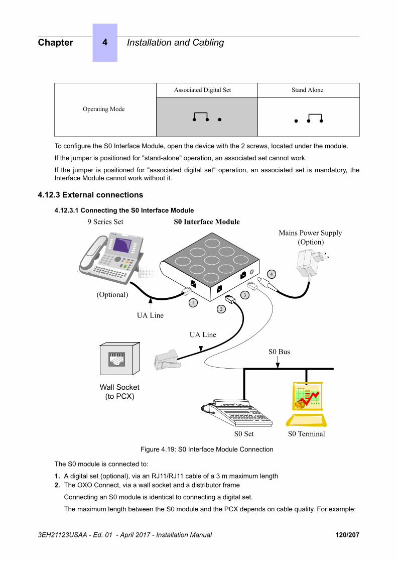
Operating Mode
Stand AloneAssociated Digital Set
To configure the S0 Interface Module, open the device with the 2 screws, located under the module.
If the jumper is positioned for "stand-alone" operation, an associated set cannot work.
If the jumper is positioned for "associated digital set" operation, an associated set is mandatory, theInterface Module cannot work without it.
4.12.3 External connections
4.12.3.1 Connecting the S0 Interface Module9 Series Set S0 Interface Module
Mains Power Supply(Option)
4
Wall Socket(to PCX)
S0 Bus
UA Line
UA Line
S0 Set S0 Terminal
(Optional)1
3
2
Figure 4.19: S0 Interface Module Connection
The S0 module is connected to:
1. A digital set (optional), via an RJ11/RJ11 cable of a 3 m maximum length2. The OXO Connect, via a wall socket and a distributor frame
Connecting an S0 module is identical to connecting a digital set.
The maximum length between the S0 module and the PCX depends on cable quality. For example:
Chapter 4 Installation and Cabling
3EH21123USAA - Ed. 01 - April 2017 - Installation Manual 120/207

• LY 0.5 mm cable: up to 800 m• Ref. 278 0.6 mm cable: up to 1200 m
3. The S0 bus.4. A Mains power supply unit: AC/DC converter (see details below)
CAUTION: The mains power supply unit is used as an S0 module sectioning device. This deviceshould be easily accessible.
4.12.3.2 Alcatel-Lucent S0 Interface Module Rear Panel Details
UA
2 31
Figure 4.20: Rear Panel Details
1. RJ11 socket for UA line2. RJ45 socket for S0 bus3. Power supply socket
8 123457 6
SO Line Socket
Power Supply SocketPCX & UA Set Socket
6 1235 4
1 2
Figure 4.21: Socket Details
PCX and digital set socket:
Pin Description
1 Not used
2 External Ringing 1
3 UA line 1
4 UA line 2
5 External Ringing 2
6 Not used
S0 bus RJ45 socket:
Chapter 4 Installation and Cabling
3EH21123USAA - Ed. 01 - April 2017 - Installation Manual 121/207

Pin Description Polarity
1 Not used
2 Not used
3 Transmission +
4 Reception +
5 Reception —
6 Transmission —
7 Not used
8 Not used
Power supply socket:
Pin Description
1 0V
2 40V DC
4.12.3.3 Power Supply Details
The interface module local power supply is required only when S0 terminals do not have their own localsupply.
The power supply unit depends on country:
Reference Characteristics Country
1AF00446CAAA 230V AC/42V DC 150mA Europe
1AF00446ABAA 127V AC/44V DC 150mA Brazil
1AF00446AGAA 220V AC/42V DC 150mA Argentina
1AF00446ASAA 240V AC/42V DC 150mA Australia
1AF00446AUAA 115V AC/42V DC 150mA USA
1AF00446BAAA 230V AC/42V DC 150mA UK
4.12.3.4 Environment
Working temperature: 5°C to 45°C
Stocking temperature: -40°C to 70°C
Relative humidity: 5% to 85%
Chapter 4 Installation and Cabling
3EH21123USAA - Ed. 01 - April 2017 - Installation Manual 122/207

4.13 Intelligent Base Stations
4.13.1 Detailed descriptionThis notice describes the rules to follow for an installation comprising three or four DECT bases.
For a larger installation, a preliminary study must be carried out using coverage tools. The bases arethen installed according to the results of this study.
4.13.1.1 Connection
The Alcatel-Lucent 4070 IO is designed for internal installation in the building, while the Alcatel-Lucent4070 EO is designed for external installation.
The 4070 EO IBS comes in a plastic box and is protected against temperature variation.
The 2 antennae are outside the box so that they both have the same signal reception.
Intelligent Base Stations (IBS) are fitted with a red LED that gives information about the state of theBase Station:
• Fixed LED:
1. Software downloading
2. Initialization phase, waiting for synchronization
3. Software problem, IBS stopped.• Fast blink: There is a problem with the line.• Short ON, long OFF: Running on 1 UA link.• 500ms OFF, 500ms ON: Running on 2 UA link.
The IBSs can run and be powered remotely by the UA access (this is the most common configuration).But they can also be powered by a power device. This is used when there are a lot of IBSs and thesystem power cannot support all the connected IBSs.
A base station may be connected to 1 or 2 UA links (UAI boards) and allows 3 or 6 simultaneousconnections with DECT/GAP terminals.
The need for three or six communication channels depends on the number of cordless stations and onthe DECT traffic to be managed.
In the event of a two-cable connection:
• use two interfaces neighboring a UAI board• use the odd-numbered interface for the master link and the other for the slave link.
Both cables should have the same length. The first interface of the system’s UAI16 board shouldnot be used since the operator station uses those points.
Chapter 4 Installation and Cabling
3EH21123USAA - Ed. 01 - April 2017 - Installation Manual 123/207
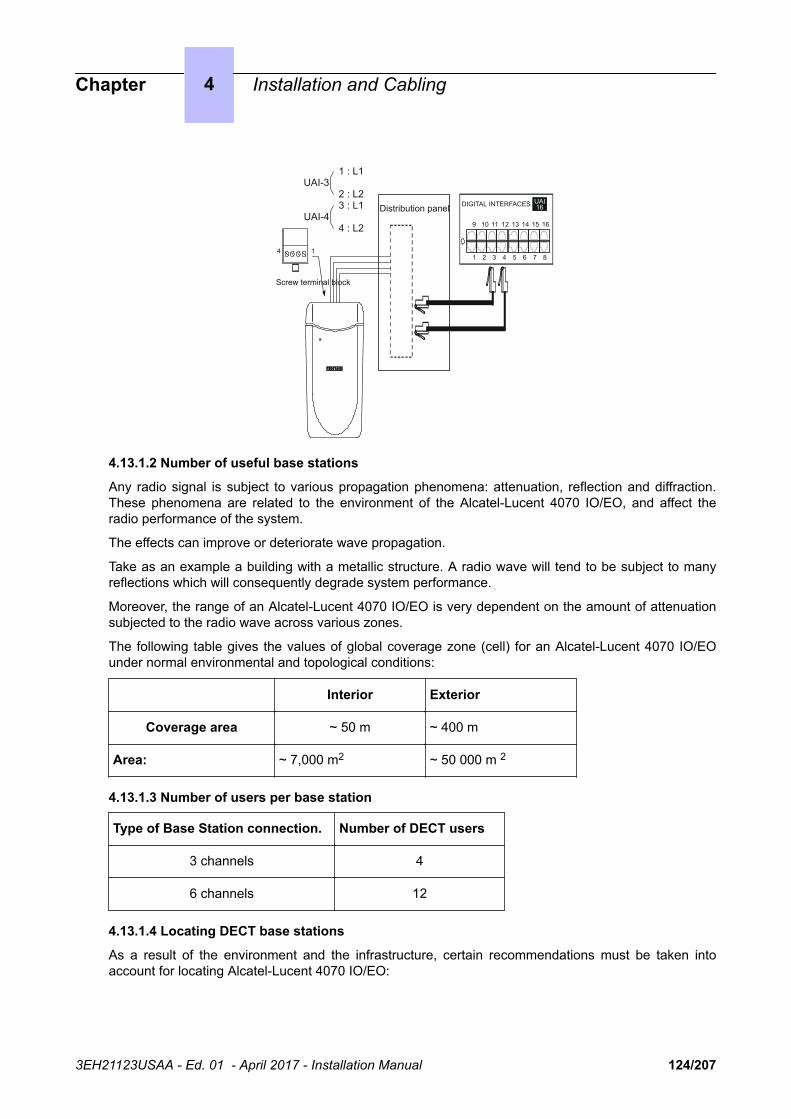
Screw terminal block
4
Distribution panel DIGITAL INTERFACES UAI16
1 2 3 4 5 6 7 8
9 10 11 12 13 14 15 16
1
UAI-3
UAI-4
1 : L1
2 : L23 : L1
4 : L2
4.13.1.2 Number of useful base stations
Any radio signal is subject to various propagation phenomena: attenuation, reflection and diffraction.These phenomena are related to the environment of the Alcatel-Lucent 4070 IO/EO, and affect theradio performance of the system.
The effects can improve or deteriorate wave propagation.
Take as an example a building with a metallic structure. A radio wave will tend to be subject to manyreflections which will consequently degrade system performance.
Moreover, the range of an Alcatel-Lucent 4070 IO/EO is very dependent on the amount of attenuationsubjected to the radio wave across various zones.
The following table gives the values of global coverage zone (cell) for an Alcatel-Lucent 4070 IO/EOunder normal environmental and topological conditions:
Interior Exterior
Coverage area ~ 50 m ~ 400 m
Area: ~ 7,000 m2 ~ 50 000 m 2
4.13.1.3 Number of users per base station
Type of Base Station connection. Number of DECT users
3 channels 4
6 channels 12
4.13.1.4 Locating DECT base stations
As a result of the environment and the infrastructure, certain recommendations must be taken intoaccount for locating Alcatel-Lucent 4070 IO/EO:
Chapter 4 Installation and Cabling
3EH21123USAA - Ed. 01 - April 2017 - Installation Manual 124/207

Recommendations for location Possible solutions
INTERIOR COV-ERAGE
As far as possible from walls Suspend Alcatel-Lucent 4070 IO/EO in aclear zone
Do not fix directly to a metallic structure Move Alcatel-Lucent 4070 IO/EO into an-other zone
Do not place in false ceilings or in telecomrooms
Place Alcatel-Lucent 4070 IO/EO in usefulzones (corridors)
As far as possible from industrial machinesor electrical cabinets
Place 4070 IO/EO in useful zones
EXTERNAL COV-ERAGE
Place the base stations in an open space(as far as possible from buildings)
Attached to pylons for example
Place the base stations higher than low ob-stacles (trees, cars etc.)
At the top of buildings on pylons for exam-ple
4.13.1.5 Interactions
Interactions with other features
IBS DECT and IBS PWT (Personal Wireless Telecommunications) cannot run together on the samesystem. The first IBS plugged determines the system type (DECT or PWT).
To switch from one system to another, unplug all IBSs, make a warm restart and plug in the IBSs.
Interactions with other applications
IBSs are fully compatible with other wireless technologies such as VOWLAN.
Interactions with other software releases
OXO Connect release 5.1 requires 4 kinds of DECT initialization: Europe, Latin America, United-Statesand China. See also: IBS configuration on page 126.
4.13.1.6 Limits
Number of IBSs: 20 IBSs per cabinet is recommended, however, the number of IBSs is only restrictedby the available power.
DECT link limit: 3 links on an IBS with one UA access, 6 links on an IBS with 2 UA accesses.
DECT handset limit: up to 120 handsets on a system.
4.13.1.7 Performance and quality
IBSs are downloaded during the system start phase or when hot plugged. A system with many IBSsplugged might take longer to complete the start phase.
Downloading 1 IBS takes about 30 seconds. It takes more time when several IBSs are plugged on thesame UA resource.
The end of restart is only possible after all the devices have been taken into account.
If an IBS downloading fails, the IBS restarts with the previously installed software.
Chapter 4 Installation and Cabling
3EH21123USAA - Ed. 01 - April 2017 - Installation Manual 125/207

4.13.1.8 IBS configuration
There is no hardware configuration for IBS other than selecting between an external power supply foreach IBS and remote power by system.
To configure the IBS software:
ARI Number
The ARI number identifies each OXO Connect. Each OXO Connect has an identical default ARInumber.
When you install a new OXO Connect, you have to change the default ARI number. You can only keepthe first digit, which is "1" and which means "ARI type B".
• 1 In OMC, go to System Miscellaneous -->DECT/PWT ARI/GAP• 2 Enter your own number (octal digit) to register your DECT handset.
Figure 4.22: ARI Number
Note:
The ARI Number is the only non plug and play device on the IBS.
The default configuration fits with the major systems. Modifications should answer to specific needs.
Line length
The Line length is the cable length used to plug the IBS to the system (distance between the IBS andOXO Connect). It enables the system to add a delay in signal and to avoid a shift in clock signal thatcreates a reset of the IBS.
• 1 In OMC, go to Users/Base stations List.• 2 Select the IBS Master and click Details
There are 3 possibilities of configuration:
• Short line (0-400 meters)• Medium line (400-800 meters)• Long line (800-1200 meters)
Chapter 4 Installation and Cabling
3EH21123USAA - Ed. 01 - April 2017 - Installation Manual 126/207

Restart the IBS after you have modified the Line length parameter.
Antenna diversity
Antenna diversity is the ability of the IBS to move the transmission and reception from one antenna tothe other so that the signal is always of the highest quality.
Restart the IBS after you have modified the Antenna diversity parameter.
Silent-Noisy IBS
Enable the Silent-Noisy IBS parameter to set up the echo canceller device.
The IBS is fitted with a software device that analyses audio signals and eliminates echo and noises.This device is activated by default.
When an IBS is deployed in a noisy environment, a lot of signals, including Speech ones, areeliminated while in Conversation state. This leads to bad Speech quality.
You have the option to disable the echo canceller. In that way, the speech and the noise signals are notfiltered. It is then to the user to identify the speech.
Frequency plan
In OMC, go to System Miscellaneous→ DECT/PWT Frequencies to select signals. In OMC, you canconfigure both the DECT and PWT frequency plans, regardless of what types of handsets are pluggedon the system.
Figure 4.23: DECT/PWT Frequencies
Chapter 4 Installation and Cabling
3EH21123USAA - Ed. 01 - April 2017 - Installation Manual 127/207

Note:
Due to hardware, there is a limit in the number of channels that you can configure.
You can configure the following numbers of channels:
• DECT EUROPE, LATAM, CHINA: 1, 2, 4, 5, 8, 10 channels• DECT US: 1, 2, 4, 5 channels• PWT: 1, 2, 4, 5, 8 channels
4.13.1.9 Initialization
Once the IBS finishes the downloading, the system starts the initialization.
The system synchronizes the signals of the IBSs so that handovers are possible. The system selectsthe T0, T2, or CPU main board clock as the source.
Then the system sends the following data:
• Fixed part capabilities (Full slot, frequency control, page repetition, setup on dummy, basic A fieldsetup): value sent = 0x007910
• Line length: Short line• Frequency plan (2 bytes)
Some countries have shifted DECT frequencies. In order to be compatible with all frequency bands inthe different countries, 4 types of initialization of frequency plans are available:
Europe, Latin America, The United-States and China.
table 4.7: RF Band Europe
Channel TX Freq RX Freq
0 1897.344 1898.206
1 1895.616 1896.480
2 1893.888 1894.752
3 1892.160 1893.024
4 1890.432 1891.296
5 1888.704 1889.566
6 1886.978 1887.840
7 1885.248 1886.112
8 1883.520 1884.384
9 1881.792 1882.656
Note:
By default, all frequencies used
Value sent to IBS: 0x3FF
0000 0011 1111 1111
Chapter 4 Installation and Cabling
3EH21123USAA - Ed. 01 - April 2017 - Installation Manual 128/207

table 4.8: RF Band China
Channel TX Freq RX Freq
0 1918.060 1918.944
1 1916.352 1917.216
2 1914.624 1915.446
3 1912.898 1913.760
4 1911.188 1912.032
5 1919.440 1910.304
6 1907.712 1908.576
7 1905.964 1906.848
8 1904.256 1905.120
9 1902.528 1903.392
Note:
By default, all frequencies used
Value sent to IBS: 0x3FF
0000 0011 1111 1111
table 4.9: RF Band Latam
Channel TX Freq RX Freq
0 1928.448 1929.312
1 1926.720 1927.584
2 1924.992 1924.992
3 1923.264 1923.264
4 1921.536 1921.536
5 1919.808 1919.808
6 1918.060 1918.060
7 1916.352 1916.352
8 1914.624 1914.624
Chapter 4 Installation and Cabling
3EH21123USAA - Ed. 01 - April 2017 - Installation Manual 129/207

9 1912.896 1912.896
Note:
By default, all frequencies used
Value sent to IBS: 0x3FF
0000 0011 1111 1111
table 4.10: RF Band US
Channel TX Freq RX Freq
3 1928.448 1929.312
4 1926.720 1927.584
5 1924.992 1925.856
6 1923.264 1924.128
7 1921.536 1922.400
Note:By default, only 5 frequencies used
Value sent to IBS: 0x03E0
0000 0011 1110 0000
table 4.11: RF Band PWT
Channel Center Freq
0 1929.375
1 1928.125
2 1926.875
3 1925.625
4 1924.375
5 1923.125
6 1921.875
7 1920.625
Note:
By default, 8 frequencies used
Value sent to IBS: 0x03FC
Chapter 4 Installation and Cabling
3EH21123USAA - Ed. 01 - April 2017 - Installation Manual 130/207

0000 0011 1111 1100
4.13.2 Safety rules
4.13.2.1 Environmental protection
For an exterior installation, it is necessary to take precautions against lightning affecting the location ofthe 4070 IO/EO.
4.13.2.1.1 Conditions for using lightning protection
Protection of 4070 IO/EO against lightning should be used when they:
• Are less than 1.5 m from a wall more than 2 m below the antenna.• Use an external airborne connection between the base station and the system.
4.13.2.2 Recommendations for exposure of the public to the electromagnetic field4.13.2.2.1 Magnetic absorption rate
Exposure of the public to the electromagnetic field from DECT sets and base stations is measuredusing the Specific Absorption Rate (SAR) measuring unit. 2 W/kg is the SAR limit value indicated ininternational recommendations and also in the European recommendation (1999/519/EC).
The DECT authorized SAR limit value is 2 W/kg on 10 g of body tissue (local SAR). Internationalrecommendations include a safety margin for the public and take account of possible measuringvariations.
SAR values
• Set: as the average power emitted from a set is lower than 20 mW, the set is considered to complywithout having to undergo any tests (see: EN 50371). The SAR value for DECT sets is notsignificant.
• Base station: the local SAR (head and chest) on 10 g of body tissue for DECT base stations (e.g.:4070) is lower than 0.5 W/kg (this is with an integrated omni-directional antenna).
4.13.2.2.2 Antennae characteristics4.13.2.2.2.1 Integrated antennae
The following is a list of characteristics for integrated antennae:
• Bandwidth: 1.88 to 1.93 Ghz• Impedance: 50 Ohms• TOS: 1.5:1• Gain: 3 dBi (maximum)• Polarization: vertical (axis of the antenna)• Width of the beam at 3 dB (vertical): 90º• Radiation diagram: omni-directional in the horizontal plane.
4.13.2.2.2.2 External antennae
According to the ETSI EN 301 406 standard, DECT antenna gain is limited to 12 dB +/-3dB. In the caseof external directional antennae, if a minimum safety distance of 50 cm is respected, the SAR value isthe same as the value obtained in the case of an integrated omni-directional antenna (and therefore,lower than: 0.5 W/kg).
4.13.2.2.3 Conformance perimeter for exposure of the public
• Integrated omni-directional antennae: no limit for the conformance perimeter• External antenna (directional): the installation must allow for a safety perimeter respecting a
minimum distance of 50 cm.
Chapter 4 Installation and Cabling
3EH21123USAA - Ed. 01 - April 2017 - Installation Manual 131/207

4.13.2.3 Recommendations for installation4.13.2.3.1 Standard Topology
The various building infrastructures are grouped into three types of geometric shape.
Coverage areas SQUARE: Coverage areas RECTANGU-LAR :
Coverage areas ROUND
The distances quoted below give an idea of typical range of a base station. It is clear that a rectangularzone requires more base stations to provide full coverage.
4.13.2.3.2 Layout technique
For structures with a number of floors, different solutions can be envisaged as a function of:
• the coverage obtained at each level.• the position of the 4070 IO/EO (higher or lower level).
4.13.2.3.2.1 Installation examples
Square zone Rectangular zone
2
1
1
2
11 2
2 2 floor terminalsnd
1 1 floor terminalsst
Example 1: square building Example 2: rectangular building
1st floor 1st floor
Chapter 4 Installation and Cabling
3EH21123USAA - Ed. 01 - April 2017 - Installation Manual 132/207
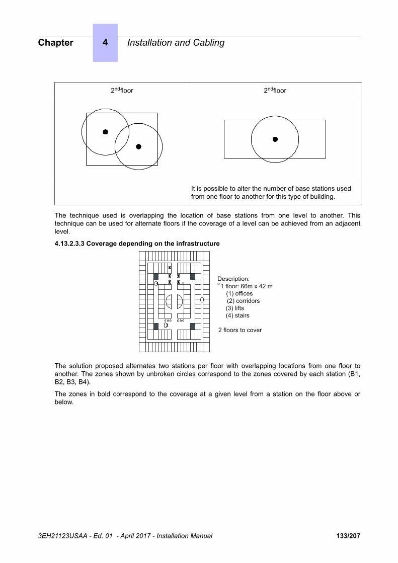
2ndfloor 2ndfloor
It is possible to alter the number of base stations usedfrom one floor to another for this type of building.
The technique used is overlapping the location of base stations from one level to another. Thistechnique can be used for alternate floors if the coverage of a level can be achieved from an adjacentlevel.
4.13.2.3.3 Coverage depending on the infrastructure
2
4
1
Description:1 floor: 66m x 42 m
(1) offices (2) corridors (3) lifts (4) stairs
2 floors to cover
st
The solution proposed alternates two stations per floor with overlapping locations from one floor toanother. The zones shown by unbroken circles correspond to the zones covered by each station (B1,B2, B3, B4).
The zones in bold correspond to the coverage at a given level from a station on the floor above orbelow.
Chapter 4 Installation and Cabling
3EH21123USAA - Ed. 01 - April 2017 - Installation Manual 133/207
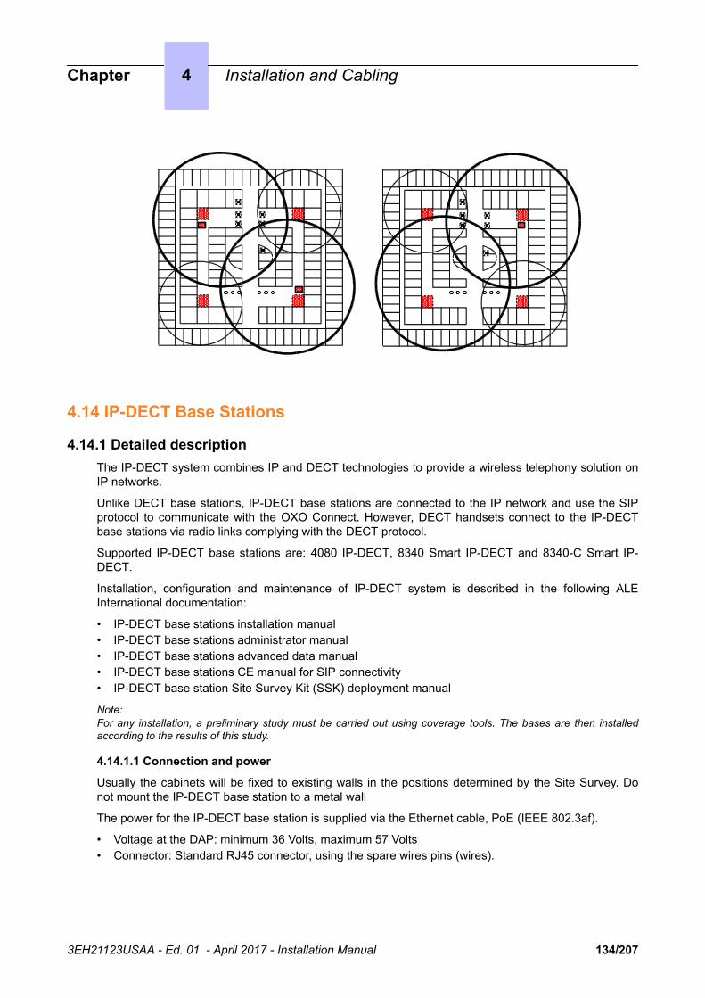
4.14 IP-DECT Base Stations
4.14.1 Detailed descriptionThe IP-DECT system combines IP and DECT technologies to provide a wireless telephony solution onIP networks.
Unlike DECT base stations, IP-DECT base stations are connected to the IP network and use the SIPprotocol to communicate with the OXO Connect. However, DECT handsets connect to the IP-DECTbase stations via radio links complying with the DECT protocol.
Supported IP-DECT base stations are: 4080 IP-DECT, 8340 Smart IP-DECT and 8340-C Smart IP-DECT.
Installation, configuration and maintenance of IP-DECT system is described in the following ALEInternational documentation:
• IP-DECT base stations installation manual• IP-DECT base stations administrator manual• IP-DECT base stations advanced data manual• IP-DECT base stations CE manual for SIP connectivity• IP-DECT base station Site Survey Kit (SSK) deployment manual
Note:For any installation, a preliminary study must be carried out using coverage tools. The bases are then installedaccording to the results of this study.
4.14.1.1 Connection and power
Usually the cabinets will be fixed to existing walls in the positions determined by the Site Survey. Donot mount the IP-DECT base station to a metal wall
The power for the IP-DECT base station is supplied via the Ethernet cable, PoE (IEEE 802.3af).
• Voltage at the DAP: minimum 36 Volts, maximum 57 Volts• Connector: Standard RJ45 connector, using the spare wires pins (wires).
Chapter 4 Installation and Cabling
3EH21123USAA - Ed. 01 - April 2017 - Installation Manual 134/207

8 7 6 5 4 3 2 1
DAP RJ45 Socket
8=7=6=5=4=3=2=1=
RTN (0 Volt) power100 Base-T RX-+48 Volt Power+48 Volt power100 Base-T RX +100 Base- T TX-100 Base-T TX+
RTN (0 Volt) power
Figure 4.24: Pin Layout Ethernet Connector RJ45 on the DAP
The IP-DECT base station access points are fitted with 2 LEDs that provide information about thestatus.
• Top LED – Yellow
This LED represents the status of the IP-DECT base station.
LED Status (Top LED, Yellow) Meaning
Off No power
0,5 sec. On - 0,5 sec. Off Loading software/firmware
Short flash every 0,25 seconds IP Network error (not connected, no DHCP/TFTP serv-er, no DAP Controller
Fast blink DAP operational, but trying to synchronize to anotherDAP
Continuous fast blink Hardware error
Steady On DAP operational (and synchronized to other DAP or isthe synchronization master)
Note:
The colour of the top LED can be different depending on the operational mode.
• Normal (single band) mode
In the normal single band mode, the top LED will be Yellow.• Dual Band
Mode In Dual Band mode, the LED colour shows the operational frequency:
• Green: Europe/International• Red: North America / USA
• Lower LED – Red/Green
This LED is used to indicate the start-up and network status.
LED Status (lower LED, Red/Green) Meaning
RED Steady on Power but FPGA starting up
Chapter 4 Installation and Cabling
3EH21123USAA - Ed. 01 - April 2017 - Installation Manual 135/207

RED flashing Trying to connect to the network
Green flashing Network status display and showing network activity
Off IP-DECT base station operational
4.15 PIMphony
4.15.1 OverviewPIMphony is a personal productivity tool that connects your phone terminal (dedicated, analog orDECT wireless set) with your computer, providing enhanced usage of your telephone.
PIMphony IP is an IP phone that provides the same level of features as PIMphony associated with anactual terminal. PIMphony IP is based on Voice over IP technology (VoIP). No physical terminal isrequired.
PIMphony also provides tight integration with the most popular PIMs (Personal Information Managers)on the market, enabling them for Computer Telephony.
Note:
For information and details concerning PIMphony installation, refer to the Installation Manual section in thePIMphony Online Help.
The PIMphony Online Help is available:
• from the PIMphony CD-Rom and the Documentation CD-Rom: open the aochelp.chm file to access the OnlineHelp
• from the PIMphony application : once it is installed on your PC, press F1 to open the Online Help
4.15.2 Additional Information
4.15.2.1 Hardware aspects
table 4.12: PC Requirements
Version Hardware Requirements
PIMphony 6.8 PII 300 Mhz+ 128MB Ram + 2 GB HD (140 MB freespace to install PIMphony) + SVGA (1024x768) +Ethernet Board + Keyboard + Mouse
Sound card for PIMphony IP
USB port or serial port for use of a headset with PIM-phony IP
Chapter 4 Installation and Cabling
3EH21123USAA - Ed. 01 - April 2017 - Installation Manual 136/207

4.15.2.2 Software aspects
table 4.13: Supported and unsupported software
Supported WindowsOS
See Table 3
Unsupported WindowsOS
All Windows version before Windows Vista 32/64 bits edition
Only for PIMphony Multimedia : Windows 2008 Server/R2 Server
It is not recommended to use PIMphony 6.8 in other than the above men-tioned OS list.
Windows 8 RT is not supported
Internet Explorer Internet Explorer 6.0 or more recent
Office Outlook 2000, XP, 2003, 2007, 2010 (32 bits and 64 bits edition), Outlook2013 [32 bit and 64 bit], Outlook 2016 [32 bits and 64 bits]
Access 2000, XP, 2003, 2007, 2010 (32 bits edition), 2013 (32 bits edition)
Goldmine Goldmine 5.7
Goldmine 6.5, 6.7, 7.0, 7.5, 8.0, 8.5, 9.0, 9.2
Act Act! 6, Act! 2006 (8.0), Act! 2007 (9.0), Act! 2008 (10.0), Act! 2009 (11.0),Act! 2010 (12.0), Act! 2011 (13.0), Act! 2012 (14.0), Act! 2013 (15.0), Act!2014 (15.0), Act! 2015 (17.2)
Lotus Notes IBM Lotus Notes 5.02 to 6.5, Lotus Notes 8.0, Lotus Notes 8.5, LotusNotes 8.5.3., Lotus Notes 9.0.
table 4.14: Supported Windows OS
OS PIMphony PIMphonyIP
TSP SPI forMicrosoftTAPIServer
Windows 2008 Server (with SP2) [32 bits] Yes No No Yes
Windows 2008 R2 Server (with SP1) [64 bits] Yes No No Yes
Windows Vista 32 bits edition (with SP1) Yes Yes Yes No
Windows Vista 64 bits edition (with SP1) Yes No No No
Windows 7 (with SP1) [32/64bit] Yes Yes Yes No
Windows 8 32 bits edition Yes Yes Yes No
Windows 8 64 bits edition Yes Yes Yes No
Chapter 4 Installation and Cabling
3EH21123USAA - Ed. 01 - April 2017 - Installation Manual 137/207

OS PIMphony PIMphonyIP
TSP SPI forMicrosoftTAPIServer
Windows 8.1 32 bits edition Yes Yes Yes No
Windows 8.1 64 bits edition Yes Yes Yes No
Windows 2012 64 bits server Yes No No Yes
Windows 10 32 bits edition Yes Yes Yes No
Windows 10 64 bits edition Yes Yes Yes No
Windows 2012 R2 Server Yes No No Yes
4.15.2.3 Limits
Maximum number of simultaneous connected PIMphony users: 200
4.16 PIMphony Touch
4.16.1 OverviewPIMphony Touch is a software client application running on a tablet or computer using a WindowsOperating System. For more information on the minimum system requirements (hardware and OSssupported), refer to the Cross Compatibility.
Since VoIP stack is not implemented, this application needs to be associated with a physical set. Itprovides access to enterprise telephony services. This Windows app requires the network connectionto interact with OXO Connect.
PIMphony Touch can be used in only one profile: the Pro profile. A PIMphony Touch Pro license onsystem side is needed.
The PIMphony Touch available features are:
• Call History• Visual Voice Mail• Dialer• Click a telephone number from a different PC application to dial it• Search (UDA)• Favorites• Programmable keys• Incoming call notifications• Instant Messaging• Live Tiles• Routing rules• SMTP notification• Telephonic presence (in favorites and banner)• Trace logs• LAN/WAN access
Chapter 4 Installation and Cabling
3EH21123USAA - Ed. 01 - April 2017 - Installation Manual 138/207

• Multilanguage support
The number of simultaneous connected PIMphony Touch users is limited. For more information, referto the Capacity and Limits section of document [1].
For information and details (Installation, User Manual) about PIMphony Touch, refer to the PIMphonyTouch On Line Help:
• A Help entry is available in the settings screen displayed as flyout when the user clicks settings inthe Charms bar (The charms bar is a vertical bar on the Windows start page, to the right of thecomputer screen, which displays only when the mouse cursor is placed in the top right corner orbottom right corner of the PC screen)
• When the user clicks this Help entry, an intermediate screen is displayed with a brief description ofthe help for the PIMphony Touch application
• At the end of this description, a click on a link opens the PIMphony Touch On Line Help in thedefault browser of the PC/Tablet. The PIMphony Touch On Line Help is hosted on a website.
4.16.2 Architecture
4.16.2.1 Overview
This module presents the network topologies to access the PBX services from PIMphony Touch.
PIMphony Touch can connect to the PBX (that is OXO Connect) using the Wi-Fi network of theenterprise (On site topology on page 139) or the internet network (WAN) when moving outside theenterprise (Off-site topology (home worker) on page 140).
PIMphony Touch relies on Microsoft Windows Push Notification Services (WNS), used to sendnotifications from the PBX to PIMphony Touch. When the PBX sends an event, it generates a pushnotification and sends a request to the WNS. The WNS receives the request and routes the notificationto the appropriate PIMphony Touch. The notification is then displayed in a toast window, live tile, or lockscreen.
A web proxy can be configured for the network. In this case, the web proxy details must be configuredin OMC. For more information, see Engineering rules on page 140.
PBXWNS
NotificationsNotifications
PIMphony Touch
4.16.2.2 On site topology
Within company premises, PIMphony Touch relies on the company intranet network (LAN) for voicemedia and data transmission. PIMphony Touch connects to the company intranet network using awireless connection (Wi-Fi network).
The intranet DNS server must be configured to resolve the private FQDN of the PBX.
Chapter 4 Installation and Cabling
3EH21123USAA - Ed. 01 - April 2017 - Installation Manual 139/207

Voice
DataIntranet(LAN)
Wi-Fi internetnetwork
PIMphony Touch PBX
Figure 4.25: On-site topology example
4.16.2.3 Off-site topology (home worker)
Outside company premises, PIMphony Touch relies on the internet network (also called WAN) for voicemedia and data transmission. PIMphony Touch can connect to the internet network using the Wi-Fiinternet network (home spot or public hotspot).
This requires to configure the following elements:
• The firewall protecting the intranet (company LAN). It must allow access to the PBX ports• The Internet DNS server used to resolve FQDNs of network elements, when PIMphony Touch
connects to the PBX
Voice
DataIntranet(LAN)
Wi-Fi internetnetwork
Internet(WAN)
PIMphony Touch
PBXRouter/Firewall
Figure 4.26: Off-site topology example
4.16.2.4 Engineering rules
Connection between OXO Connect and the WNS:
• A connection to Internet must be available.• The DNS server IP addresses must be configured in OMC in Hardware and Limits > LAN / IP
Configuration > DNS/DHCP tab. This is necessary to resolve the WNS name coded in the OXOConnect, so that the OXO Connect can reach the Windows Notification server directly.
Connection between the applications and OXO Connect:
• To receive the WNS notifications, OXO Connect and the devices (PIMphony Touch / OTCVWindows) must have an internet connection.
• The port used by the applications to reach OXO Connect must be open on the access router andredirected to the WAN port of OXO (default: 50443).
• The URL services must be authorized: https://host/services/Ics/7.0/• The URL for event must be authorized.
Configuration with web proxy:
Chapter 4 Installation and Cabling
3EH21123USAA - Ed. 01 - April 2017 - Installation Manual 140/207

• The web proxy details must be configured in OMC in Hardware and Limits > LAN / IPConfiguration > Web proxy tab.
4.17 Extending Your Installation
4.17.1 Configuration of Stations
4.17.1.1 Handset replacement
You can replace your digital terminal by connecting a terminal of the same family, but of a differenttype, into your phone socket. This substitution can be temporary or permanent.
Replacing an analog set by another analog set, or replacing a digital set by a set of the same type,requires no special procedure (simple hardware exchange).
4.17.1.1.1 Temporary substitution
The replacement set keeps its own default functions (customized settings are not transferred). Thedata not transferred is stored in the OXO Connect system until a set of the same type as the initial oneis connected.
Unplug Plug in Plug inUnplug
Defectiveterminal
Repairedterminal
Replacementterminal
Your terminal is unserviceable Your terminal is repaired
Replacementterminal
4.17.1.1.2 Permanent replacement
The maximum quantity of data from the initial set is transferred to the replacement. Data not transferredare deleted.
Unplug Plug in
terminal terminal
"Terminal replacement"code + password
ReplacementDefective
4.17.1.1.3 Characteristics preserved during temporary or permanent set substitution
• Rights (restricted features)• Barring level• Metering profile• Messages and last caller repertories• Destination set for metering reminder, forwarding and/or monitoring• Set belonging to a hunting group and/or a Manager-Secretary relation• Appointment reminder• Locked or unlocked set• Callbacks• Active forwarding• Last number redial
Chapter 4 Installation and Cabling
3EH21123USAA - Ed. 01 - April 2017 - Installation Manual 141/207

4.17.1.1.4 Replacement of digital sets
Regardless of the type of the initial digital set and that of the replacement, the function and resourcekeys are not preserved. The directory numbers are preserved in accordance with the size of thedirectories of the stations concerned.
The add-on modules are always transferred provided the substitution set supports these modules.
4.17.1.2 IP Touch set replacement
You can replace your IP Touch terminal by connecting a terminal of the same family only, into yourphone socket. This substitution can be temporary or permanent.
4.17.1.2.1 Temporary substitution
The default configuration is not preserved when replacing temporarily an IP Touch set by another typeof IP Touch set. The activation code and the replacement functions will be refused.
The data downloading process is automatically activated and the correct files are selected.
4.17.1.2.2 Permanent replacement
The default configuration is not preserved when replacing permanently an IP Touch set by another typeof IP Touch set. The activation code and the replacement functions will be refused.
The data downloading process is automatically activated and the correct files are selected.
4.17.1.3 Moving a handset
If you move office, you can move your set from one socket to another and still preserve all or part of itssettings.
Before relocating the set:
• You need to change the personal code, which must be different from the default code.• It is advisable to lock the set.
4.17.1.3.1 Relocating a set to an unused socket
Unplug Plug in
Movement
"Terminal movement" code+ Dir. P1+ password(not default password)
4.17.1.4 Adding sets
When adding sets, attention must be paid to the limits on the number of sets and the features offeredby the system software key.
Plug in
The set is recognized as soon as it has been plugged into the socket.
Chapter 4 Installation and Cabling
3EH21123USAA - Ed. 01 - April 2017 - Installation Manual 142/207

4.17.2 Adding/Replacing Boards
Except for the PowerCPU EE, any board can be plugged/unplugged when the system is poweredup.
To replace a PowerCPU EE board:
• Press the ON/OFF button, the RED led will flash.• Wait for the LED to go to steady red (about 30 seconds): the system is turned off.
With OMC you can save and subsequently restore the configuration after replacing the PowerCPU EEboard.
4.17.3 Adding a Module ExpansionIt is possible to add one or two modules to the basic module.
BUSINESS PROCESSING UNIT
LAN
LAN CONFIG.
DOORPHONEAUDIO MODULEMODULE 1
FAN POWER
CPUMODULE 2
AUX
ISDN T0 1 ISDN T0 2
SLI1/2 &
Mini-MIX
MODULE EXPANSION
MAIN
FAN POWER
POWER MEX
MODULE EXPANSION
MAIN
FAN POWER
POWER MEX
PowerCPU EE board
POWER MEX board (extension cabinet 1)
POWER MEX board (extension cabinet 2)
STP 100-Ohm cables Category 5 (provided)Length 5m
PowerCPU EE
4.17.3.1 Fitting a Module Expansion
• The CPU slot of the module expansion must be fitted with a PowerMEX board with an HSL1daughter board.
• Fit the PowerCPU EE board of the main module with an HSL daughter board.• A module expansion may only include synchronous digital network interfaces (BRA, PRA) if this
type of card is already incorporated into the main module (synchronization by the main module).• The same rules apply to the other boards as those which applied to the base module.
Chapter 4 Installation and Cabling
3EH21123USAA - Ed. 01 - April 2017 - Installation Manual 143/207

4.17.3.2 PowerMEX board.MODULE EXPANSION
MAIN
FAN POWER
POWER MEX
RJ45 pin 1 2 3 4 5 6 7 8
MAIN: TX+ TX- RX+ RX-
• MAIN: HSL to basic module.
4.17.3.3 Role of the # key
Name Color Feature
POWER Red/Green • Mains operation: steady green led• Battery operation: steady yellow led• Standy: steady red LED
FAN Red/Green • Both fans functioning: steady green led• 1 or both fans down: steady red led
4.17.3.4 Adding a third module
• Replace the HSL1 board of the PowerCPU EE board with an HSL2 board.• Reuse this HSL1 board by placing it on the PowerMEX board of the third module.
In an installation using two modules, the PowerCPU EE (base module) and PowerMEX (moduleexpansion) boards are fitted with an HSL1 board.
4.17.4 Installation UpgradeThis section outlines the major considerations to be taken into account when migrating to OXOConnect R2.1 from OXO Connect R2.0 or OmniPCX Office RCE R3.1, R4.1, R5.1, R6.1, R7.1, R8.2,R9.2 or R10.3.
Migration must be performed on site, except when there is no hardware change and the PowerCPU EEremains the system's CPU.
4.17.4.1 On Site Migration
On site migration applies when the CPU is changed (PowerCPU replaced by a PowerCPU EE).
4.17.4.1.1 Prerequisites
To carry out an upgrade to OXO Connect R2.1, you need:
• A migration kit for the new CPU (PowerCPU EE)• The correct version of OXO Connect R2.1 with the associated software licenses• OMC R21.0• LOLA 400/18.1 or higher
Chapter 4 Installation and Cabling
3EH21123USAA - Ed. 01 - April 2017 - Installation Manual 144/207

4.17.4.1.2 Migration to OXO Connect R2.1Note:Migration from a PowerCPU running an OmniPCX Office RCE RCE release to a PowerCPU EE running an OXOConnect R2.0 (or higher) can only be performed from LOLA.
To migrate the system to OXO Connect R2.1:
• From an OXO Connect R2.0:
1. Use the OMC R21.0 to save configuration data from the current CPU2. Use the OMC to download/swap without data saving to OXO Connect R2.13. Use the OMC to restore the configuration data previously saved in the current CPU
• From an OmniPCX Office RCE R3.1, R4.1, R5.1, R6.1, R7.1:
1. Use the OMC R21.0 to save configuration data from the current CPU2. In OMC off-line, adapt the saved database to OXO Connect R2.1 hardware level (change CPU
type, remove CoCPUs)3. Use LOLA to save customer data from the current main CPU (select option Migration mono
CPU)4. Unplug the CPU and the unsupported boards from the system5. Change the existing hardware for OXO Connect R2.1 hardware6. Plug the new CPU7. Use LOLA to install the OXO Connect R2.1 in the new CPU8. Use LOLA to restore the previously saved customer data in the new main CPU9. Use OMC to restore the previously saved and modified configuration data in the new main CPU
• From OmniPCX Office RCE R8.x, R.9.x, R10.1, R10.2:
1. Use the OMC R21.0 to save configuration data from the current CPU2. Use the OMC to download/swap without data saving to OXO Connect R2.13. Use the OMC to restore the configuration data previously saved in the current CPU
• From OmniPCX Office RCE R10.3:
1. Use the OMC R21.0 to save (backup) configuration data from the current CPU2. Use the OMC to download/swap with data saving to OXO Connect R2.1
4.17.4.2 Remote Migration
Remote migration may be performed when the CPU remains the same (PowerCPU EE). It is alsopossible for a migration from OmniPCX Office RCE R10.3 to OXO Connect R2.1.
4.17.4.2.1 Prerequisites
To carry out an upgrade to OXO Connect R2.1, you need:
• OMC R21.0
4.17.4.2.2 Migration to R10.x OXO Connect Small, Medium, Large and OXO Connect Compact
1. Use the OMC R21.0 to save configuration data from the current CPU2. Use the OMC to download/swap without data saving to OXO Connect R2.13. Use the OMC to restore the configuration data previously saved in the current CPU
4.17.4.3 Configuration
After the hardware upgrade and migration, use the OMC configuration procedures to configure theOXO Connect.
Chapter 4 Installation and Cabling
3EH21123USAA - Ed. 01 - April 2017 - Installation Manual 145/207

4.18 My IC Plugin for Outlook®
4.18.1 Detailed description
4.18.1.1 Introduction
My IC Plugin for Outlook® is an Outlook Add-In user application which runs on the user's Windowsbased PC and integrates Microsoft Outlook, Windows Live Messenger (MSN), Yahoo!, Facebook andSkype with OXO Connect Call Management and Control. It enables the user to optimizecommunications by providing consolidated presence information and by presenting a variety ofcommunication options such as voice, E-mail, SMS and Instant Messaging (IM).
My IC Plugin for Outlook® offers direct one-touch interaction between a user’s telephony, E-mail,calendar and IM, bringing together the most popular forms of communications. My IC Plugin forOutlook® improves user productivity and simplifies communications.
This document details the prerequisites and installation process of the My IC Plugin for Outlook®
application.
4.18.1.2 Network Topologies
My IC Plugin for Outlook® uses the Microsoft TAPI interface to connect to the OXO Connect PCXthrough which the basic telephony services are supported. My IC Plugin for Outlook® can operate in 2different network modes:
• TAPI 2.0 Client• TAPI 2.1 Server
The mode selection is made during the installation of My IC Plugin for Outlook® software on the enduser’s PC.
1. TAPI 2.0: Client mode
If there are 25 or fewer computers that will be accessing the OXO Connect, then My IC Plugin forOutlook® can be installed on each end user PC to connect directly to the OXO Connect. In thistopology the OXO Connect TSP software (see note below) is automatically installed on the enduser’s PC during the installation of the My IC Plugin for Outlook® software.
Note:ALE International has developed a TAPI Service Provider (TSP) to interconnect OXO Connect to TAPIapplications like My IC Plugin for Outlook®. This TSP is a driver which translate Microsoft world (TAPI protocol)to OXO Connect world (CSTA protocol) and conversely for call control.
2. TAPI 2.1: Server mode
For deployments exceeding 25 users, a TAPI server is required. This functionality is available inWindows Server operating systems. In this topology the OXO Connect TSP software is installed ona separate Windows Server computerthat is configured to connect to the OXO Connect switch. Thiscomputeris referred to as the TAPI Server. All end user computers with My IC Plugin for Outlook®
will then connect to the TAPI Server which acts as a signalling relay for call control, instead ofconnecting directly to the OXO Connect PBX. Configuring a TAPI server is beyond the scope of thisdocument.
Once lines have been allocated to users on the TAPI Server, end users can install My IC Plugin forOutlook® on their PC and select "Connect using a remote TAPI server" when prompted during theinstallation. More installation details are described in Installation on page 148. Connecting with aremote TAPI server will require that My IC Plugin for Outlook® software key is in the OXO Connectas well as the TAPI 2.1 software key for the Windows Server computer. See Licensing on page 147.
Chapter 4 Installation and Cabling
3EH21123USAA - Ed. 01 - April 2017 - Installation Manual 146/207

Note:The Windows TAPI Server does not only provide a larger number of sessions, it also provides a more secureadministration environment based on Microsoft Active Directory, thus it can also be used for a configuration ofless than 25 users.
4.18.1.3 Pre requisites
To be able to use My IC Plugin for Outlook®, a user must have a valid extension line configured on anOXO Connect and a supported phone connected to this line. The list of supported devices can beconsulted in the delivery note.
A TAPI session for each user must be available.
4.18.1.3.1 OXO Connect TAPI licensing.
My IC Plugin for Outlook® requires that TAPI be effective on the OXO Connect . As TAPI can be sharedwith other applications, there must be at least one TAPI 2.0 free session per My IC Plugin for Outlook®
user or a TAPI 2.1 server must be installed when there is not enough free TAPI 2.0 sessions for the MyIC Plugin for Outlook® number of users.
OXO Connect comes with 25 TAPI 2.0 sessions. If more than 25 sessions are needed the TAPI 2.1software licence must be bought in addition and provisioned in the OXO Connect .
4.18.1.3.2 Operating system and applications
The My IC Plugin for Outlook® application supports:
• Windows Vista SP2 Business, Ultimate or Enterprise (32 OR 64 bit)• Windows 7 Professional, Ultimate or Enterprise (32 OR 64 bit)• Windows 8 (32 or 64 bit) but Windows 8 RT not supported• Windows 8.1 (32 or 64 bit)• Windows 10 (32 or 64 bit)• .Net Framework 3.5 Service Pack 1 – refer to the Microsoft Knowledge Base article (http://
msdn.microsoft.com/en-us/kb/kb00318785.aspx).• Microsoft Outlook: (32 bit only): 2003, 2007, 2010, 2013• Microsoft Exchange: 2003, 2007, 2010• Skype (optional): 3.8.0.188 or later• Live Messenger (optional): 14.0 or later• Yahoo! (optional): 10.0 or later• Facebook (optional): Direct link to the current Facebook website• OXO Connect: Release 9.0 or later• Windows Installer 3.1
4.18.1.3.3 Hardware
• 1 GHz 32-bit (x86) or 64-bit (x64) processor• 1 GB of system memory• At least 40 MB of available space for installation and an additional 10 MB of available space for
configuration and cached contact data• A Network Connection. 10Mb/s minimum
4.18.1.4 Licensing
To run My IC Plugin for Outlook®, the OXO Connect must be provisioned with one My IC Plugin forOutlook® user software licence per user.
The number of My IC Plugin for Outlook® user software licence can be reviewed using the OXOConnect Management Console (OMC), version 9 or later.
Chapter 4 Installation and Cabling
3EH21123USAA - Ed. 01 - April 2017 - Installation Manual 147/207

1. From Modification typical, select System2. In the Software Key tab, click the Details button
The CTI tab of the Software Key Features dialog will shows a list of e-applications with their sessionlimits, including My IC Plugin for Outlook®
If no My IC Plugin for Outlook® user software licence are available or if all of them are currently in use,then upon launching Outlook, My IC Plugin for Outlook® will report that no valid licence has beenfound, and to contact your administrator. Nevertheless My IC Plugin for Outlook® will install and runwhen Outlook is started and all features (except telephone) features will be available for the user.
In case of TAPI server configuration (see section 2) it also requires the TAPI 2.1 software key for theWindows Server computer providing 200 concurrent sessions (max).
My IC Plugin for Outlook® can be installed with a Try and Buy License whose validity period is 60 days.
4.18.1.4.1 Offline mode (Out of office) licensing
My IC Plugin for Outlook® may be used outside the office where no connection to the OXO Connect isavailable, such as on portable laptop computers, it provides many useful features in this situation thatdo not require access to the phone switch. This ability is granted based on the last time that My ICPlugin for Outlook® was able to connect to the OXO Connect. If the licence check failed then My ICPlugin for Outlook® will not run outside the office, else the off-line mode is allowed for 4 weeks.
4.18.1.5 Installation4.18.1.5.1 Software installation
My IC Plugin for Outlook® is installed on individual PCs as a two part process
1. My IC Plugin for Outlook® Installation Wizard is performed by an Administrator or System Installer,who has intimate knowledge of the customer’s infrastructure
2. My IC Plugin for Outlook® Configuration Wizard, which is executed when the application is launchedfor the first time and can be performed by the end user. This uses the information provided by theAdministrator/System Installer to simplify the installation process
4.18.1.5.1.1 My IC Plugin for Outlook® Installation Wizard
Before starting the installation, make sure that Outlook and PIMphony are not running (even inbackground)
Before starting the installation, make sure that .Net 3.5. SP1 is installed.
My IC Plugin for Outlook® requires Microsoft .Net Framework version 3.5 with Service Pack 1 tooperate correctly. To determine if .Net 3.5 SP1 is already installed, please refer to the MicrosoftKnowledge Base article (http://msdn.microsoft.com/enus/ kb/kb00318785.aspx )
1. Run the My IC Plugin for Outlook® setup.exe2. Click Yes if you receive a UAC (user account control) warning (Windows Vista, 7 or later)3. Select the installation language from the languages available, click OK4. On the “Welcome Screen”, click Next5. Read and Accept the license Agreement, click Next6. Select if My IC Plugin for Outlook® is to connect:
• directly to the OXO Connect (<=25 TAPI users), or• via a remote TAPI server (>25 TAPI users)
Click Next to continue.
If you select TAPI Server, the next windows will ask you to indicate the Remote TAPI Server Name(or IP address). Click Next
7. Choose whether or not to enable Yahoo! integration, click Next
Chapter 4 Installation and Cabling
3EH21123USAA - Ed. 01 - April 2017 - Installation Manual 148/207

Note:This does not install Yahoo! Messenger, but authorizes My IC Plugin for Outlook® to access Yahoo! Messengerif it is installed
8. Confirm the folder to install the program into, click Next9. Confirm the folder to install the program shortcuts into, click Next10.Click Install to begin the installation and click Finish when the installation is complete to start the
Configuration Wizard
If the configuration Wizard does not continue, it can be launched at any moment from the windowsmenu:
Start > All Programs > Alcatel-Lucent > My IC Plugin for Outlook
4.18.1.5.1.2 My IC Plugin for Outlook® Configuration Wizard:
1. On the "Introduction" screen, click Next2. Enter the IP Address of the OXO Connect , click Next3. The configuration wizard will connect to the OXO Connect .
If successfully connected, a list of available line extensions on the OXO Connect is presented.
If unsuccessful, the invitation to enter the correct IP Address for the OXO Connect is presented.4. Select the line to control and enter the voice mailbox password for that line extension, click Next5. The configuration wizard will now authenticate the line and password with the OXO Connect6. When successful, click Finish to complete the setup.
If unsuccessful, the invitation to select a line and enter the correct password is displayed.7. The configuration Wizard can be launched at any moment from windows menu:
Start > All Programs > Alcatel-Lucent > My IC Plugin for Outlook8. Once the installation is completed, start Outlook, My IC Plugin for Outlook® panel will appear within
Outlook interface on the right as native Outlook windows
Note:Please ensure that TAPI configuration is setup by checking the "Location", "Area Code" and "Dialling Rules" in theTAPI control panel. Please refer to Phone and Modem Options on page 152 for more details.
Chapter 4 Installation and Cabling
3EH21123USAA - Ed. 01 - April 2017 - Installation Manual 149/207

Note:It is not advisable to do the installation of My IC Plugin for Outlook® on a PC while connected to the publishedlocation via a VPN. Use the LAN connection to the OXO Connect
4.18.1.5.2 Software Uninstall
My IC Plugin for Outlook® can be uninstalled using standard Windows conventions from Control Panel.
The uninstall process does NOT remove any user configuration.
Uninstalling My IC Plugin for Outlook® will not uninstall the Alcatel-Lucent TAPI Service Provideror .NET Framework and will not impact PIMphony.
4.18.1.5.3 Software Update
My IC Plugin for Outlook® can be updated simply by installing a new software version. The installer willautomatically remove the old version and install the new one without impacting any of the userinformation or installed applications.
4.18.1.6 Service Reliability
Each of the Outlook, OXO Connect, Skype & Live Messenger, Yahoo!, Live Messenger, Facebook andIntelligent Quick Dialling (IQ) groups of features are provided by a My IC Plugin for Outlook® service(not to be confused with a Windows service). My IC Plugin for Outlook® attempts to start each of theseservices on startup. Upon failure a service will be scheduled for a restart after approximately 1 minute.
If a given service fails to start, the functions provided by the service will be unavailable to the user.Furthermore contacts provided by the service will either be unavailable or the contact details will bemaintained but the presence will be unavailable.
Service Software information is available from the "Diagnostics" window, available by clicking on the "i"button (bottom right corner of the My IC Plugin for Outlook® panel) then clicking the Diagnosticsbutton. For more information, see Diagnostic file on page 151.
4.18.1.7 Basic Troubleshooting4.18.1.7.1 Networking or System Problems
To check network connectivity to the OXO Connect, make sure you are able to ping the OXO ConnectIP Address via Command prompt from the PC that has My IC Plugin for Outlook® installed and makesure a reply is received. Command prompt can be accessed as follows:
• From Windows Vista & Windows 7: Start > All Programs > Accessories > Command Prompt.
In the Command prompt type:
ping <OmniPCX Office IP Address>Note:
To change the IP address of the OXO Connect on the My IC Plugin for Outlook® PC, go to Control Panel >Phone & Modem Options > Advanced
Select Alcatel TAPI Service Provider and change the Switch Name and Address or
Use the My IC Plugin for Outlook® Phone Configuration available at:
Start > All Programs > Alcatel-Lucent > My IC Plugin for Outlook
Chapter 4 Installation and Cabling
3EH21123USAA - Ed. 01 - April 2017 - Installation Manual 150/207

To check if the versions of Exchange/Outlook/Skype/Yahoo!/Live Messenger are supported:
• Exchange: Check the version of Exchange with your System Administrator• Outlook: Click on Help > About Microsoft Office Outlook• Skype: Click on Help > About Skype• Yahoo!: Click on Help > About Yahoo!• Live Messenger: Click on Help > About Messenger• Facebook: Check the current web site
To check if the Operating System & Hardware meets the minimum requirement for My IC Plugin forOutlook®:
• Windows Vista & Windows 7: Click Start and then Right Click on My Computer and selectProperties
To check if the Client meets the .NET Framework requirement for My IC Plugin for Outlook®:
• Windows Vista & Windows 7: Click on Start > Control Panel and Programs and Features
4.18.1.7.2 Diagnostic file
Chapter 4 Installation and Cabling
3EH21123USAA - Ed. 01 - April 2017 - Installation Manual 151/207

To display the diagnostics
1. With My IC Plugin for Outlook® running, click on the information icon
This is a small icon at bottom right corner of the My IC Plugin for Outlook® Panel2. Click on “Diagnostics”3. You can click on Export to produce a file that can be renamed and saved on your disk.
The file contains diagnostic information that can be provided to the Technical Support.
4.18.1.7.3 Log files
These files can be used for deep investigations by ALE International technical experts.
• The logs in Windows Vista & Windows 7 are written to:
C:\Users\<user>\Application Data\Local\Alcatel Lucent\Social Networks\log.fdb
4.18.1.7.4 Communication Add-ins
Add-ins are third party tools that integrate seamlessly with Outlook. To find the add-ins:
• Outlook 2010 & Outlook 2013:
File >Options >Add-Ins > Manage Comm Add-ins and click Go• Outlook 2007:
Tools > Trust Centre > Add-Ins > Manage Comm Add-ins and Click Go• Outlook 2003:
Tools > Options >Other >Advanced Options > COM Add-In
How to use the information:
• If My IC Plugin for Outlook® is registered with Outlook. It will appear in this list.• If My IC Plugin for Outlook® is successfully loaded then it will be checked and the load behavior
label will say loaded at start up• If My IC Plugin for Outlook® does not successfully load, the tick box will be unchecked and an error
message is displayed against the load behavior label.
4.18.1.7.5 Dialing Rules
My IC Plugin for Outlook® uses the Phone/Modem Dialling Rules of the PC for it's own dialling rule.
Changes to the Phone/Modem Dialling Rules will result in changes to the displayed numbers within MyIC Plugin for Outlook®.
The number displayed next to the My IC Plugin for Outlook® contact, is the actual number My IC Pluginfor Outlook® will dial.
The number displayed by the "Hint" when hovered over the number, is the original number obtainedfrom the imported directory.
4.18.1.7.6 Phone and Modem Options
My IC Plugin for Outlook® uses the Windows "Phone and Modem" rules in order to make calls. Thesesettings can be found in:
Control Panel > Phone and Modem Options
Chapter 4 Installation and Cabling
3EH21123USAA - Ed. 01 - April 2017 - Installation Manual 152/207

In this example, the outside line access for local and long-distance calls is "9".
Additional information about these settings can be found at: http://windows.microsoft.com/en- US/windows-vista/Phone-and-Modem-Options-setting-up-dialing-locations
4.18.1.7.7 Digit for External Line
Using OXO Connect Management Console (OMC)
Navigate to Numbering > Numbering Plans,
Chapter 4 Installation and Cabling
3EH21123USAA - Ed. 01 - April 2017 - Installation Manual 153/207

Select the Internal Numbering Plan tab and identify the Main Trunk Group
In this example, the access code for an external line is "0". For your specific installation, please checkwith your OXO Connect system installer.
4.19 ACD applications
4.19.1 Platforms supported by ACD applicationsThe following platforms are supported for the Agent Assistant, Supervisor Console, and StatisticsManager applications:
• Windows VISTA (32 bits with SP2)• Windows 7 (32/64 bits with SP1)• Windows 8.1(32/64 bits)• Windows Server 2008 R2 (64 bits with SP1)• Windows 8 (32/64 bits)
Note:Windows 8 RT is not supported.
• Windows Server 2012 (64 bits)
Important:
ACD applications have been adapted to install the right functionalities they need corresponding to theframework.NET version installed on PC.
For that, one of the framework.NET version must be installed on the PC (framework.NET 2.0 orframework.NET 3.5 with 2.0 option checked or framework.NET 4.0):
• If only framework.NET 4.0 is installed, then one version of the DLL is installed for ACD applications• If framework.NET 2.0 is installed or if framework 3.5 with the 2.0 option checked, then another
version of the DLL is installed for ACD applications• If both versions are installed on the same PC, the DLL of framework.NET 4.0 functionalities is then
installed
In addition, the minimal display resolution of the screen must be: 1024 x 768 pixels
Chapter 4 Installation and Cabling
3EH21123USAA - Ed. 01 - April 2017 - Installation Manual 154/207

4.19.2 InstallationFor Windows 8/2012, make sure that .NET Framework 3.5 is installed. To determine if .NETFramework 3.5 is already installed, please refer to the Microsoft Knowledge Base article (http://msdn.microsoft.com/enus/ kb/kb00318785.aspx ).
1. Run the setup.exe2. Follow the displayed instructions.
Chapter 4 Installation and Cabling
3EH21123USAA - Ed. 01 - April 2017 - Installation Manual 155/207

Chapter
5 Station Default configuration
5.1 Default configuration
5.1.1 8038 Premium DeskPhone, 8039 Premium DeskPhone and 8068 PremiumDeskPhone sets
Each of these sets has 2 programmable keys (F1/F2) and 40 virtual add-on keys. Their defaultfunctions depend on:
• The configuration of the set (Operator, Manager, Assistant, Normal or Attendant)• The market in which the set is sold (US or non-US)• The operating mode of the set (KeySystem or PABX mode)
The default functions of the F1/F2 keys are summarized in the table below (they are the same forKeySystem and PABX modes).
table 5.1: F1/F2 Key Functions
Market Set Configuration Key F1 Key F2
Non-US Operator Normal/Restricted Mode Operator Diversion
Manager Secretary Screening
Secretary Manager Screening
Normal Call Call
US Operator Manual Hold Transfer
Manager Manual Hold Transfer
Secretary Manual Hold Transfer
Normal Manual Hold Transfer
The default functions of the virtual keys are summarized in the figures below (separate figures areprovided for the US market). The virtual keys are selected using 8 physical buttons, 4 on each side ofthe set's display. There are 5 pages of virtual keys (the pages can be scrolled through using the up/down buttons of the set's 4-way navigator), with 8 virtual keys on each page. Each of the followingfigures shows the first page of virtual keys and then indicates the progression to the last (fifth) page ofvirtual keys.
3EH21123USAA - Ed. 01 - April 2017 - Installation Manual 156/207

Int/Ext
Int/Ext
Call
Call
Block Mode
Call
Call
Call
Operator (KeySystem Mode)
:
Call
:
:
:
Call
:
:
Call
Call
Call
Call
Call
Call
Call
Call
Page 1
Page 5
Figure 5.1: Virtual Key Functions for Operator Sets in KeySystem mode
Chapter 5 Station Default configuration
3EH21123USAA - Ed. 01 - April 2017 - Installation Manual 157/207
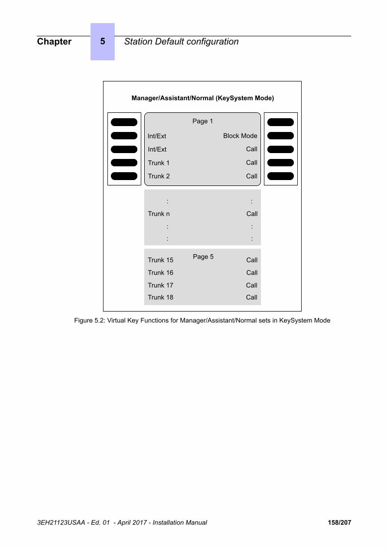
Int/Ext
Int/Ext
Trunk 1
Trunk 2
Block Mode
Call
Call
Call
Manager/Assistant/Normal (KeySystem Mode)
:
Trunk n
:
:
:
Call
:
:
Trunk 15
Trunk 16
Trunk 17
Trunk 18
Call
Call
Call
Call
Page 1
Page 5
Figure 5.2: Virtual Key Functions for Manager/Assistant/Normal sets in KeySystem Mode
Chapter 5 Station Default configuration
3EH21123USAA - Ed. 01 - April 2017 - Installation Manual 158/207
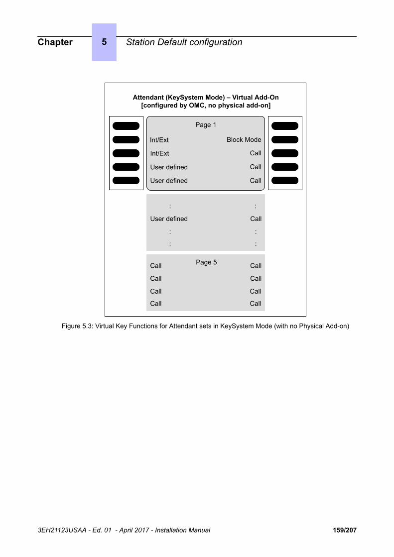
Int/Ext
Int/Ext
User defined
User defined
Block Mode
Call
Call
Call
Attendant (KeySystem Mode) – Virtual Add-On[configured by OMC, no physical add-on]
:
User defined
:
:
:
Call
:
:
Call
Call
Call
Call
Call
Call
Call
Call
Page 1
Page 5
Figure 5.3: Virtual Key Functions for Attendant sets in KeySystem Mode (with no Physical Add-on)
Chapter 5 Station Default configuration
3EH21123USAA - Ed. 01 - April 2017 - Installation Manual 159/207

Int/Ext
Int/Ext
Call
Call
Block Mode
Call
Call
Call
Attendant (KeySystem Mode)[configured by OMC, physical add-on present]
Page 1
Page 5Call
Call
Call
Call
Call
Call
Call
Call
Trunk 1
Trunk 3
Trunk 5
Trunk 7
Trunk 2
Trunk 4
Trunk 6
Trunk 8
Call
Call
Call
Call
Call
Call
Call
Call
:
Call
:
:
:
Call
:
:
Trunk 9
:
Trunk n
:
Call
Call
:
:
Page 1
Page 5
Virtual Add-On Physical Add-On
Figure 5.4: Virtual and Physical Add-on Key Functions for Attendant Sets in KeySystem mode
Chapter 5 Station Default configuration
3EH21123USAA - Ed. 01 - April 2017 - Installation Manual 160/207

Int/Ext
Int/Ext
Int/Ext
Int/Ext
Do Not Disturb
Normal/Restricted Mode
Operator Diversion
Call
Operator (KeySystem Mode) – US Only
Call
:
:
:
Call
:
:
:
Call
Call
Call
Call
Call
Call
Call
Call
Page 1
Page 5
Page 2
Figure 5.5: [US only] Virtual Key Functions for Operator Sets in KeySystem Mode
Chapter 5 Station Default configuration
3EH21123USAA - Ed. 01 - April 2017 - Installation Manual 161/207

Int/Ext
Int/Ext
Int/Ext
Int/Ext
Do Not Disturb
Assistant or Manager
Screening
Call
Manager/Assistant (KeySystem Mode) – US Only
Trunk 1
Trunk 2
:
:
Call
:
:
:
Trunk 13
Trunk 14
Trunk 15
Trunk 16
Call
Call
Call
Call
Page 1
Page 5
Page 2
Figure 5.6: [US only] Virtual Key Functions for Manager/Assistant Sets in KeySystem Mode
Chapter 5 Station Default configuration
3EH21123USAA - Ed. 01 - April 2017 - Installation Manual 162/207

Int/Ext
Int/Ext
Int/Ext
Int/Ext
Do Not Disturb
Call
Call
Call
Normal (KeySystem Mode) – US Only
Trunk 1
Trunk 2
:
:
Call
:
:
:
Trunk 13
Trunk 14
Trunk 15
Trunk 16
Call
Call
Call
Call
Page 1
Page 5
Page 2
Figure 5.7: [US only] Virtual Key Functions for Normal Sets in KeySystem Mode
Chapter 5 Station Default configuration
3EH21123USAA - Ed. 01 - April 2017 - Installation Manual 163/207

Int/Ext
Int/Ext
Int/Ext
Int/Ext
Block Mode
Call
Call
Call
Operator/Manager/Assistant/Normal (PABX Mode)
Call
:
:
:
Call
:
:
Call
Call
Call
Call
Call
Call
Call
Call
Page 1
Page 5
:
Page 2
Figure 5.8: Virtual Key Functions for Operator/Manager/Assistant/Normal Sets in PABX Mode
Chapter 5 Station Default configuration
3EH21123USAA - Ed. 01 - April 2017 - Installation Manual 164/207

Int/Ext
Int/Ext
Int/Ext
Int/Ext
Do Not Disturb
Normal/Restricted Mode
Operator Diversion
Call
Operator (PABX Mode) – US Only
Call
:
:
:
Call
:
:
:
Call
Call
Call
Call
Call
Call
Call
Call
Page 1
Page 5
Page 2
Figure 5.9: [US only] Virtual Key Functions for Operator Sets in PABX Mode
Chapter 5 Station Default configuration
3EH21123USAA - Ed. 01 - April 2017 - Installation Manual 165/207

Int/Ext
Int/Ext
Int/Ext
Int/Ext
Do Not Disturb
Assistant or Manager
Screening
Call
Manager/Assistant (PABX Mode) – US Only
Call
:
:
:
Call
:
:
:
Call
Call
Call
Call
Call
Call
Call
Call
Page 1
Page 5
Page 2
Figure 5.10: [US only] Virtual Key Functions for Manager/Assistant Sets in PABX Mode
Chapter 5 Station Default configuration
3EH21123USAA - Ed. 01 - April 2017 - Installation Manual 166/207

Int/Ext
Int/Ext
Int/Ext
Int/Ext
Do Not Disturb
Call
Call
Call
Normal (PABX Mode) – US Only
Call
:
:
:
Call
:
:
:
Call
Call
Call
Call
Call
Call
Call
Call
Page 1
Page 5
Page 2
Figure 5.11: [US only] Virtual Key Functions for Normal Sets in PABX Mode
5.1.2 8028 Premium DeskPhone, 8029 Premium DeskPhone setsEach of these sets has 2 programmable keys (F1/F2) and 40 virtual add-on keys. Their defaultfunctions depend on:
• The configuration of the set (Operator, Manager, Assistant, Normal or Attendant)• The market in which the set is sold (US or non-US)• The operating mode of the set (KeySystem or PABX mode)
The default functions of these keys are the same as for the sets detailed in 8038 Premium DeskPhone,8039 Premium DeskPhone and 8068 Premium DeskPhone sets on page 156. However, in this casethe virtual keys are selected using 4 physical buttons, 2 on each side of the set's display, as shownbelow.
Buttons to access virtual keys
Chapter 5 Station Default configuration
3EH21123USAA - Ed. 01 - April 2017 - Installation Manual 167/207

There are 10 pages of virtual keys (the pages can be scrolled through using the up/down buttons of theset's 4-way navigator), with 4 virtual keys on each page.
5.1.3 Alcatel-Lucent IP Touch 4018 Phone setThis set has 6 programmable keys which have the default functions indicated below.
Int/Ext
Int/Ext
Forward
Conference
Transfer
Call
Int/Ext
Int/Ext
Forward
Conference
Manual Hold
Transfer
US Only
Figure 5.12: Key functions for Normal sets (in PABX mode)
5.1.4 Other predefined data• Level 1 dynamic routing of stations: any unanswered call is routed to the voice mail unit after 12
seconds.• Level 2 dynamic routing of stations: only external call are routed to the operator group after 24
seconds.• OS calls overflow to general level (default operator group) after 24 seconds• The default operator group contains the first two integrated voice server ports, general ringer,
remote XRA access and the first Alcatel Reflexes interface (Operator station)• All the stations (except analog stations) are given a voice mailbox.• The first analog interface is a Fax.
Chapter 5 Station Default configuration
3EH21123USAA - Ed. 01 - April 2017 - Installation Manual 168/207

Chapter
6 Start-Up
6.1 System startup from a phone setYou can start-up the system using a Premium DeskPhone (8038 Premium DeskPhone/8058s PremiumDeskPhone, 8039 Premium DeskPhone, 8068 Premium DeskPhone/8068s Premium DeskPhone and8078s Premium DeskPhone) set.
The phone set used needs to be defined as the operator phone set, that is the first phone setconnected to the system.
A start-up session is started automatically when the system is turned on for the first time. Follow thisstart-up session to enter the data required to operate the system.
The procedures below show the 8038 Premium DeskPhone/8058s Premium DeskPhone, 8039Premium DeskPhone, 8068 Premium DeskPhone/8068s Premium DeskPhone or 8078s PremiumDeskPhoneinterface.
In order to facilitate the first start-up, it is recommended that you have the following informationavailable:
• The number of your installation (international country prefix, national prefix, etc.).• Basic metering unit value• The ranges of numbers attributed by the network operator to the direct dial numbers (DDI) of the
terminals in your installation.
6.1.1 General dynamic keys
Previous Return to the previous menu Next Go to the next menu
Delete the last character Cancel Cancel
Choice Move between the various optionsfrom those offered OK Validate an entry
Scroll up, down, left or right on the display
6.1.1.1 First power-up
Go on
3EH21123USAA - Ed. 01 - April 2017 - Installation Manual 169/207

To restart the session from the beginning during programming.
Attend To restart the session if you quit using the Exit function
6.1.2 System type
Choice : Used to define the system type: Business or Hotel
6.1.3 Installation number
This number must be entered in its entirety. The number of your installation can include a maximumof three fields for a total of 18 digits.
The fields must be separated by an asterisk.
Possible fields include:
• International country prefix (for example: 33 for France): obligatory field.• National prefix: optional field (has no meaning in France).• Public number of the installation: obligatory field.
Chapter 6 Start-Up
3EH21123USAA - Ed. 01 - April 2017 - Installation Manual 170/207
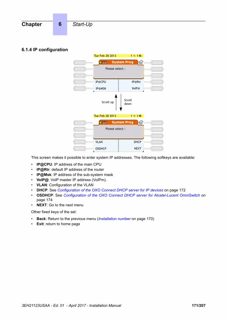
6.1.4 IP configurationTue Feb 28 2013
Please select :
IP@CPU
IP@MSK
IP@Rtr
VoIP@
Tue Feb 28 2013
Please select :
VLAN
OSDHCP
DHCP
NEXT
Scroll downScroll up
This screen makes it possible to enter system IP addresses. The following softkeys are available:
• IP@CPU: IP address of the main CPU• IP@Rtr: default IP address of the router• IP@Msk: IP address of the sub-system mask• VoIP@: VoIP master IP address (VoIPm).• VLAN: Configuration of the VLAN• DHCP: See Configuration of the OXO Connect DHCP server for IP devices on page 172• OSDHCP: See Configuration of the OXO Connect DHCP server for Alcatel-Lucent OmniSwitch on
page 174• NEXT: Go to the next menu
Other fixed keys of the set:
• Back: Return to the previous menu (Installation number on page 170)• Exit: return to home page
Chapter 6 Start-Up
3EH21123USAA - Ed. 01 - April 2017 - Installation Manual 171/207
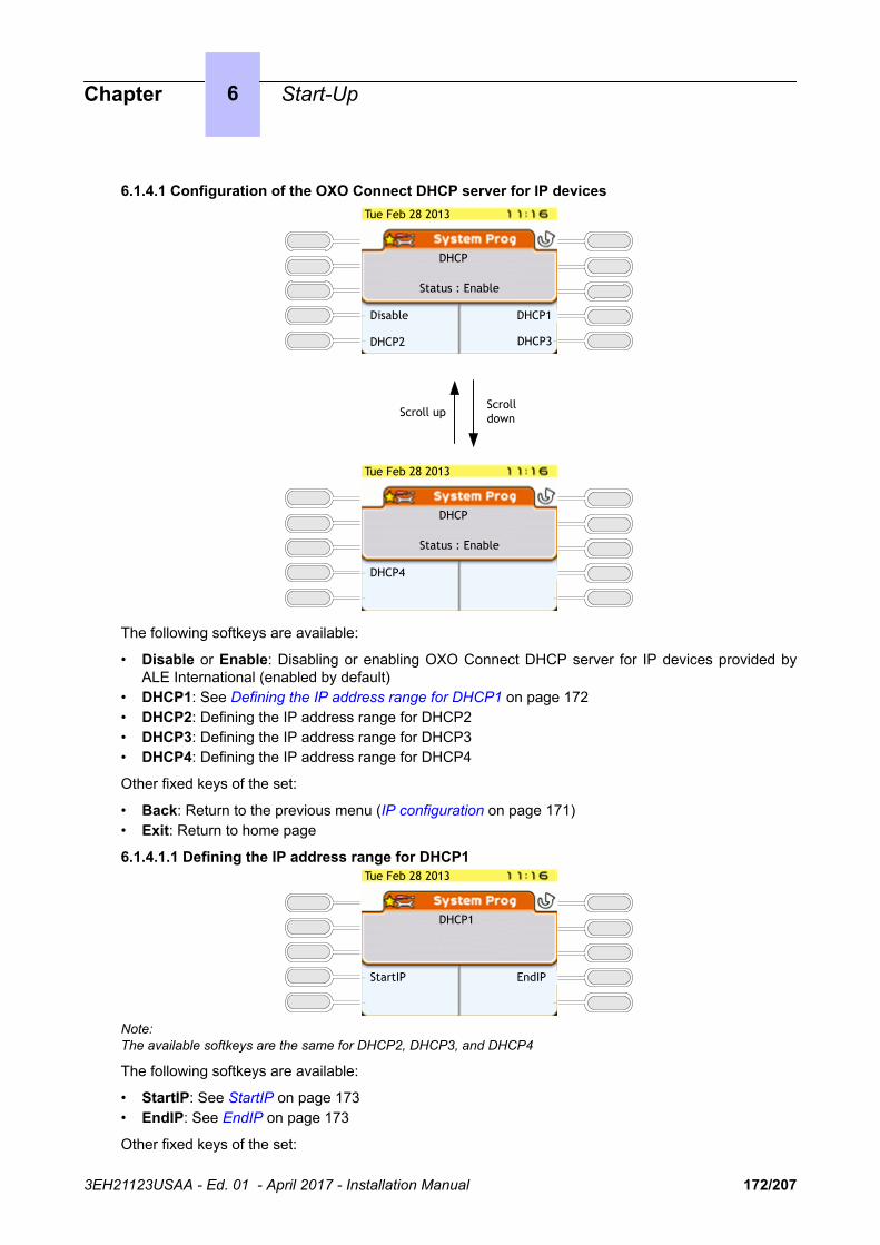
6.1.4.1 Configuration of the OXO Connect DHCP server for IP devices
Tue Feb 28 2013
DHCP
Status : Enable
DHCP4
Scroll downScroll up
Tue Feb 28 2013
DHCP
Status : Enable
DHCP1
DHCP2 DHCP3
Disable
The following softkeys are available:
• Disable or Enable: Disabling or enabling OXO Connect DHCP server for IP devices provided byALE International (enabled by default)
• DHCP1: See Defining the IP address range for DHCP1 on page 172• DHCP2: Defining the IP address range for DHCP2• DHCP3: Defining the IP address range for DHCP3• DHCP4: Defining the IP address range for DHCP4
Other fixed keys of the set:
• Back: Return to the previous menu (IP configuration on page 171)• Exit: Return to home page
6.1.4.1.1 Defining the IP address range for DHCP1Tue Feb 28 2013
DHCP1
StartIP EndIP
Note:The available softkeys are the same for DHCP2, DHCP3, and DHCP4
The following softkeys are available:
• StartIP: See StartIP on page 173• EndIP: See EndIP on page 173
Other fixed keys of the set:
Chapter 6 Start-Up
3EH21123USAA - Ed. 01 - April 2017 - Installation Manual 172/207

• Back: Return to the previous menu (Configuration of the OXO Connect DHCP server for IP deviceson page 172)
• Exit: Return to home page
6.1.4.1.1.1 StartIPTue Feb 28 2013
StartIP@: 192.168.092.010
Clear
The screen displays a default start IP address (192.168.092.010). Only DHCP1 IP address rangeincludes default IP addresses.
The following softkey is available:
• Clear: Clear the StartIP@ field
Other fixed keys of the set:
• Back: Return to the previous menu (DHCP1)• Exit: Return to home page• Left and right keys of the 4-way navigator: moving cursor in text• OK: Validation of the Start IP address field• Backspace: Deletion of one or more characters
6.1.4.1.1.2 EndIPTue Feb 28 2013
EndIP@: 192.168.092.039
Clear
The screen displays a default end IP address (192.168.092.039). Only the DHCP1 IP address rangeincludes default IP addresses.
The following softkey is available:
• Clear: Clear the EndIP@ field
Other fixed keys of the set:
• Back: Return to the previous menu (DHCP1)• Exit: Return to home page• Left and right keys of the 4-way navigator: moving cursor in text• OK: Validation of the Start IP address field• Backspace: Deletion of one or more characters
Chapter 6 Start-Up
3EH21123USAA - Ed. 01 - April 2017 - Installation Manual 173/207

6.1.4.2 Configuration of the OXO Connect DHCP server for Alcatel-Lucent OmniSwitch
The following softkeys are available:
• StartIP: See StartIP on page 174• Disable or Enable: Disabling or enabling OXO Connect DHCP server for omniswitch (enabled by
default)• EndIP: See EndIP on page 174
Other fixed keys of the set:
• Back: Return to the previous menu (IP configuration on page 171)• Exit: Return to home page
6.1.4.2.1 StartIPTue Feb 28 2013
StartIP@: 192.168.092.005
Clear
The screen displays a default start IP address (192.168.092.005)
The following softkey is available:
• Clear: Clear the StartIP@ field
Other fixed keys of the set:
• Back: Return to the previous menu (Configuration of the OXO Connect DHCP server for Alcatel-Lucent OmniSwitch on page 174)
• Exit: Return to home page• Left and right keys of the 4-way navigator: moving cursor in text• OK: Validation of the Start IP address field• Backspace: Deletion of one or more characters
6.1.4.2.2 EndIPTue Feb 28 2013
EndIP@: 192.168.092.009
Clear
Chapter 6 Start-Up
3EH21123USAA - Ed. 01 - April 2017 - Installation Manual 174/207
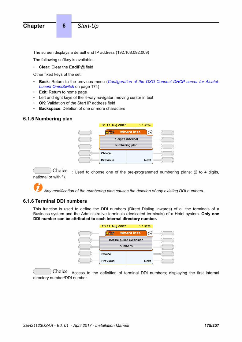
The screen displays a default end IP address (192.168.092.009)
The following softkey is available:
• Clear: Clear the EndIP@ field
Other fixed keys of the set:
• Back: Return to the previous menu (Configuration of the OXO Connect DHCP server for Alcatel-Lucent OmniSwitch on page 174)
• Exit: Return to home page• Left and right keys of the 4-way navigator: moving cursor in text• OK: Validation of the Start IP address field• Backspace: Deletion of one or more characters
6.1.5 Numbering plan
Choice : Used to choose one of the pre-programmed numbering plans: (2 to 4 digits,national or with *).
Any modification of the numbering plan causes the deletion of any existing DDI numbers.
6.1.6 Terminal DDI numbersThis function is used to define the DDI numbers (Direct Dialing Inwards) of all the terminals of aBusiness system and the Administrative terminals (dedicated terminals) of a Hotel system. Only oneDDI number can be attributed to each internal directory number.
Choice Access to the definition of terminal DDI numbers; displaying the first internaldirectory number/DDI number.
Chapter 6 Start-Up
3EH21123USAA - Ed. 01 - April 2017 - Installation Manual 175/207

The direct number includes up to 8 digit and can be modified (the cursor is placed at the start of thefield). The DDI numbers are generally the last 3 or 4 digits of your call numbers; the public operator willlet you know the range of numbers that has been assigned to you.
Down or Up Look through the list of internal directory numbers and vali-date the entry displayed.
Clear Delete the digits contained in the field "Direct no." (use the down arrow naviga-tor key to display this option)
Cancel Reject the complete list of DDI numbers as defined and return to the start of thefunction.
OK All Validate the complete list of DDI numbers.
The following error messages can appear when entering the data:
• "Number already used": the DDI number is already attributed to another internal number.• "The specified number is outside the assigned range": invalid DDI number (it contains a * or #
for example).• "Direct Dialing Table full": the maximum size of the table of public numbers (300 entries) has
been exceeded.
The following function is only available for Hotel installations.
Choice Access the definition of a pool of DDI numbers for hotel rooms; display the firstDDI number.
Chapter 6 Start-Up
3EH21123USAA - Ed. 01 - April 2017 - Installation Manual 176/207

10: Number of numbers still available in the DDI table after configuration of Direct Dial numbers.
In a Hotel installation, all the Z terminals are used as hotel room terminals (except the first which is afax and the second which is a public telephone).
A pool of DDI numbers means that these terminals can be assigned with a dynamic DDI number whena customer checks in.
The DDI numbers available depend on the number of numbers used by the administrative terminals (atotal of 300 numbers (or ranges of numbers for direct numbers) are available in the table of publicnumbers for the system). The display shows the rank of the selected entry and the total number ofentries available for the hotel rooms.
Down or Up Look through the pool of DDI numbers and validate theentry displayed.
Clear Delete the digits contained in the field "Public no." (use the down arrow naviga-tor key to display this option)
Cancel Reject the complete list of DDI numbers as currently defined and return to thestart of the function.
OK All Validate the complete list of DDI numbers.
6.1.7 Number of lines connected to the public network
This function is used to indicate the number of lines or B channels connected to the public network(120 lines or 120 B channels maximum). These lines are then introduced into the main bundle(depending on the order that the boards are taken into account) and made available using the resourcekeys. On the operator terminal, T2 access can include up to 30 B channels; T1 access up to 23 Bchannels; T0 access up to 2 B channels. The message "Value exceed number of lines connected"is displayed when the value entered is greater than the number of B channels connected.
Chapter 6 Start-Up
3EH21123USAA - Ed. 01 - April 2017 - Installation Manual 177/207

6.1.8 Operation of terminals and operator terminal
This function is only available for a business installation (in a Hotel only PCX mode is used).
Choice "PCX Mode" and"Intercom Mode"
PCX Mode: all the lines are available using two RSB keys (= resource key specific to a bundle) .
Intercom Mode: the terminal has as many RSP keys (= resource key specific to an external access)as there are lines on the system. Refer to the "Default Configuration" section in this manual for apresentation of the function of the different keys for each type of terminal depending on the operatingmode selected.
6.1.9 Attributing mailboxes
This function is used for assigning a voice mailbox to the installation terminals:
Choice : choice between UA terminals, All terminals, and No terminal.
Chapter 6 Start-Up
3EH21123USAA - Ed. 01 - April 2017 - Installation Manual 178/207

6.1.10 ARI number
This function is only available if your installation is fitted with DECT functions
The ARI (Access Right Identifier) number identifies the system uniquely to mobiles. It contains 11 octaldigits (base 8). This number, assigned to an ETSI base by the installer, must be entered on installingthe system.
The first digit cannot be modified and is always set to 1. The cursor is automatically placed on thesecond. The last digit is always either 0 or 4.
Note:This is only relevant for IBS-DECT solution.
6.1.11 Authentication
This is used to make secure data transmission between the system and DECT mobiles by using anauthentication code during registration
Choice : choice between "off" and "on".
If the authentication mechanism is "on", the following screen is displayed.
Each access code can have a maximum of ten digits. This can be limited to the first four digits if thereare DECT stations other than the 100/200 Mobiles.
Chapter 6 Start-Up
3EH21123USAA - Ed. 01 - April 2017 - Installation Manual 179/207

6.1.12 User information language
Choice Choice of language used on all the stations in the installation (display and spokenhelp)
6.1.13 Basic metering unit cost
The value of the basic metering unit is introduced for calculating the cost of external calls. The cost (notthe duration) and the changes in the charge meters during calls are displayed. The value entered cancontain 5 figures (0-2 decimal places) in the chosen monetary unit. This service is dependent on thesubscription made with the operator.
Note:Changing by duration required an external application.
6.1.14 TIME & DATEThe current date and time must be entered. Enter the date in the format DD/MM/YYYY.
Enter the time in the format HH:MM.
Chapter 6 Start-Up
3EH21123USAA - Ed. 01 - April 2017 - Installation Manual 180/207
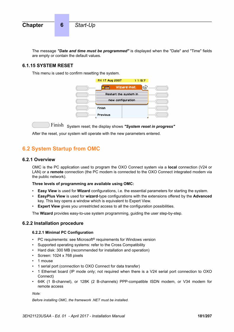
The message "Date and time must be programmed" is displayed when the "Date" and "Time" fieldsare empty or contain the default values.
6.1.15 SYSTEM RESETThis menu is used to confirm resetting the system.
Finish System reset; the display shows "System reset in progress"
After the reset, your system will operate with the new parameters entered.
6.2 System Startup from OMC
6.2.1 OverviewOMC is the PC application used to program the OXO Connect system via a local connection (V24 orLAN) or a remote connection (the PC modem is connected to the OXO Connect integrated modem viathe public network).
Three levels of programming are available using OMC:
• Easy View is used for Wizard configurations, i.e. the essential parameters for starting the system.• EasyPlus View is used for wizard-type configurations with the extensions offered by the Advanced
key. This key opens a window which is equivalent to Expert View.• Expert View gives you unrestricted access to all the configuration possibilities.
The Wizard provides easy-to-use system programming, guiding the user step-by-step.
6.2.2 Installation procedure
6.2.2.1 Minimal PC Configuration
• PC requirements: see Microsoft® requirements for Windows version• Supported operating systems: refer to the Cross Compatibility• Hard disk: 300 MB (recommended for installation and operation)• Screen: 1024 x 768 pixels• 1 mouse• 1 serial port (connection to OXO Connect for data transfer)• 1 Ethernet board (IP mode only; not required when there is a V24 serial port connection to OXO
Connect)• 64K (1 B-channel), or 128K (2 B-channels) PPP-compatible ISDN modem, or V34 modem for
remote access
Note:
Before installing OMC, the framework .NET must be installed.
Chapter 6 Start-Up
3EH21123USAA - Ed. 01 - April 2017 - Installation Manual 181/207

For Microsoft Windows 8/2012, Microsoft .NET Framework 3.5 needs to be installed before installing OMC. Aninternet connection is required for this installation.
To install the Microsoft .NET Framework 3.5:
• Select on your PC the windows Feature available in Control Panel -> Programs and Features / Programs ->Turn windows Feature on or off.
• For Windows 8: Select the .NET Framework 3.5 check box.• For Windows server 2012:
1. Select Server Manager -> Manage -> Add Roles and Features wizard2. Navigate to the Features window3. Select the .NET Framework 3.5 check box.
In case more information is needed, please contact your local administrator.
6.2.2.2 Installing the OMC Software
The OMC software is installed from a CD-ROM.
Install the application by choosing options in the various windows.
When installation is finished, you access the application either:
• By double-clicking on the new icon created on the Windows desktop, or• By selecting Start -> Program -> PCXTools -> OMC XXX yy.z. The window Welcome to OMC
appears.
6.2.3 Accessing the System
6.2.3.1 System PasswordImportant:
System Password management policy
Basic rules have to be applied to the different passwords allowing an OMC connection to the system. It isrecommended to change the default Installer password for OMC Expert, Administrator password for OMCEasyPlus and Operator password for OMC Easy.
The following are the recommendations for good password management:
• Implement company policy to regularly update all system passwords• Regularly change the passwords• Avoid the use of simple passwords such as 12345678, 11111111, 00000000 etc…• Never choose a word from everyday language. Attackers can use special dictionary cracking software
to retrieve these• Never choose a word that is closely related to you:
• your company name• your name• your wife’s maiden name• the name of your children or your pet,• your favourite hobby, etc…
• Choose a different password for each connection level• Do not disclose passwords to other persons/colleagues• Never write down your password. The first thing an attacker will do is rummage through your personal
belongings.
The rules to define management passwords are:
• Total length of 8 characters• At least one lowercase alphabet letter (a-z)• At least one uppercase alphabet letter (A-Z)
Chapter 6 Start-Up
3EH21123USAA - Ed. 01 - April 2017 - Installation Manual 182/207

• At least one digit (0-9)• Special characters are not allowed
The rules to define the operator password are:
• Total length of 8 alphanumeric characters• At least one numeric character (e.g, “HelloYou” is rejected, “11223344”, “Hello123” are accepted)• At least two different characters (e.g. “11111111”, “aaaaaaaa” are rejected)• No sequence of ascending or descending characters (e.g “12345678”, “abcdefgh” are rejected)• No special character
Administration passwords and default user password must be modified at first OMC connection.
For more information about passwords, refer to the Password Management section of the document[13].
6.2.3.2 Local Access By LAN
The default IP address for the main CPU board is 192.168.92.246 for:
• A connection to the LAN port on the main CPU board via a UTP Category 5 5-100 ohm crossovercable.
• A connection to the switch to which the main CPU board is connected by a direct cable.
The PC IP address and network mask must be compatible with the address of OXO Connect. Forexample 192.168.92.1 and 255.255.255.0.
For security reasons, the OXO Connect can be configured with an additional IP address, which is usedonly for management.
To configure a management IP address:
1. Navigate to OMC: Hardware and Limits > LAN/IP Configuration2. Select the LAN Configuration tab3. Validate the Use Management IP Address check box4. Enter the Management IP Address5. Validate6. Perform a warm reset to take the new address into account
6.2.3.3 Local V24 Access For OMC
It is possible to use OMC software to dialog with OXO Connect using a V24 connection. In this casethe network connection is not necessary.
A specific reinforced cable must link the "Config" RJ45 connector on the system CPU to the Com portof the PC using OMC.
Wiring of the connection cable
Chapter 6 Start-Up
3EH21123USAA - Ed. 01 - April 2017 - Installation Manual 183/207

RJ45 SUB D 9-point (F)
1
2
3
4
5
6
7
8
7
4
3
NC
5
2
6
8
6.2.3.3.1 Installation Procedure
1. Open the OMC software on the PC.2. Select the Expert mode.3. Select Comm from the menu toolbar.4. Select Connect from the dropdown menu. The Communication Path window is displayed.5. Select Local V24.6. The system proposes installation of OmniPCX Direct V24. Click on Yes. The Modem options
window is displayed.7. Click Add. The Installation window is displayed.8. In the Installation window, check Don't detect my modem. Propose the option in a list and click
on Next.9. Select the manufacturer.10.Select OmniPCX Direct V24.11.Select the Com port used.12.Click Next.13.Click Finish.14.Click Close.15.Back in OMC, click Comm. The Local V24 box is now enabled and the Com port is displayed.16.Click Ok and enter the password. It will take a few seconds for the OMC to connect to the system.
6.2.3.4 OMC Remote Access By Modem
With remote access, you can use OMC to configure or download an OXO Connect system. Thisaccess can be managed using:
• An ISDN modem able to use ISDN PPP (point to point) protocol at 64K (1 B-channel) or 128K (2 B-channels)
• A V34 analog modem in Hayes protocol at 33600 bds
The management of these two modems is integrated into OXO Connect.
Important:The OMC software must be installed on the remote maintenance PC, if Windows Terminal Server is notbeing used.
Chapter 6 Start-Up
3EH21123USAA - Ed. 01 - April 2017 - Installation Manual 184/207

6.2.3.4.1 Remote Access By ISDN Modem6.2.3.4.1.1 ISDN Modem Recommended
OXO Connect is equipped with a 64K (1 B-channel)/128K (2 B-channels) ISDN modem using PPPprotocol for remote access through the public network. It provides a point-to-point link accessible viastandard LINUX procedures (PPP, etc.).
For a 64K (1 B-channel) connection, the following modems are validated:
• KORTEX NOVAFAX ISDN 128000/33600 with PPP protocol• FRITZ ¡X CAPI 2.0 or any standard "FRITZ" modem• Multitech I Way Hopper MTA 128 ST 128 KBPS ISDN (see note below)
For a 128K (2 B-channels) connection, the following modems are validated:
• OLITEC USB ISDN 128K• Multitech MTA128ST-RC ML-PPP (see note below)• Eicon Diva 852 ISDN T/A USB - ISDN BRI ST - 128 Kbits/s
ISDN 64 to 128 KPBS modems handling the PPP protocol are generally compatible and support CHAPauthentication.
Note:When using the Multitech modem, the authentication method must be set to CHAP. This is the default method forcurrent firmware versions. For modems with older firmware, you must either update the firmware or activate CHAPwith the AT command AT S58=3.
6.2.3.4.1.2 RAS Installation Process
In Windows 7/Vista, you do not need to install new operating system components before configuring anew access method; the Remote Access Services (RAS) component is installed by default on thesesystems.
The sub-sections below describe how to set up the following remote access methods:
• Direct V24 Connection (OXO Connect Direct V24)• Remote connection via ISDN modem (an example is provided for driver installation)
V24 Driver Installation Procedure
1. Open the Control panel.2. Select Phone and Modem Options.3. Select the Modems tab.4. Click Add.5. Check Don't detect my modem; I will select it from the list.6. Follow the Wizard instructions to install the modem. You will need to choose the COM port that will
be associated with the modem.7. You may need to reboot the PC to complete the installation.
Installing the Driver for an ISDN Modem (example)
The following procedure describes how to install a FRITZ modem.
1. Insert the modem installation CD-ROM.2. Click the FRITZ ¡X PC Capi driver installer icon The wizard is displayed.
a. Indicate the serial port where the modem will be connected.b. When the install process is complete, reboot the PC.
3. Insert the modem installation CD-ROM. The wizard is displayed
a. Click the FRITZ ¡32 Communication Software installer icon.b. Select Install and configure.
Chapter 6 Start-Up
3EH21123USAA - Ed. 01 - April 2017 - Installation Manual 185/207

c. Use the default installation (click on Next in each Wizard screen).d. At the end of the Wizard mode, check the Install Capi-port driver box.
4. Select AVM ISDN1 Internet (PPP over ISDN).5. Reboot the PC.
6.2.3.4.1.3 Using Remote Access With OMC
1. Launch OMC. The OMC Welcome page is displayed.2. Select the appropriate menu, as follows:
• the Expert menu, if you are logging in as "installer"• the EasyPlus menu, if you are logging in as "administrator"• the Easy menu, if you are logging in as "operator" or "attendant"
3. In the toolbar menu, click Comm.4. Select Connect. The Communication Path window is displayed.5. Click Modem direct, then OK.6. Click Dialing and select AWM ISDN1 Internet (PPP over ISDN).7. Dial the customer phone number and click OK.8. Type in the appropriate password according to your user mode, Expert, EasyPlus or Easy.
Note:
The PC and B1 lights on the modem should light up when the connection is established.
The configuration session is open.
6.2.3.4.1.4 Remote Access to the ISDN Modem
When an ISDN modem is used, it is necessary to reserve a DDI number in the public numbering planto be able to establish remote access.
If no DDI number is available, check whether the system's ISDN modem access is in the defaultattendant group (default group). In this case it is not necessary to keep a DDI number.
Remark:If the modem is not currently in the attendant group, it is useful to set the Reroutdata flag to the value 01H. Thesystem then automatically recognizes the ISDN service corresponding to the incoming call and looks in the defaultattendant group for a data terminal.
6.2.3.4.2 Remote Access By The Analog Modem6.2.3.4.2.1 Analog Modem (recommended)
OXO Connect is equipped with an analog modem V34 for remote access through the public network.This modem provides a point-to-point communication link accessible via standard LINUX protocols(PPP, etc.).
Its main characteristics are:
• V34 Modem• Maximum transmission speed: 33600 bds• Hayes protocol
In the current version of the system, the V34 "US Robotic" modem has been validated. The other typesof modems were not validated.
6.2.3.4.2.2 Installation Process of the Remote Access by Analog Modem
Follow the procedures described in the previous paragraphs, but replace the FRITZ modem with theUS Robotics analog modem.
Chapter 6 Start-Up
3EH21123USAA - Ed. 01 - April 2017 - Installation Manual 186/207

6.2.3.4.2.3 Remote Access to the Analog Modem
When the analog modem is used, it is necessary to hold a DDI number in the public numbering plan inorder to be able to carry out remote maintenance.
In the case of no DDI number is available, the access to the modem will be possible only via theoperator transfer.
6.2.3.4.3 Operating Mode
1. Open OMC on the remote access PC.2. Select the Expert menu.3. Click Comm.4. Select Connect. The Communication Path window is displayed.5. Click Modem direct, then OK.6. There are two ways of establishing a remote connection:
• Select a modem phone book entry in the Used Entry field of the Modem Connection window.• Click Dialing, select the modem to use ("used modem"), then dial the customer remote access
number in the Number field.7. Enter the system's default password pbxk1064. It will take a few seconds for the connection to be
established.
6.2.3.4.4 Security
In the remote access, the protocol used in the "data link" OSI layer is PPP (Point-to-Point Protocol).The TCP/IP protocols are used respectively in the "transport" and "network" layers. For each layer,OXO Connect carries out an access control.
6.2.3.4.4.1 Authentication
At the start of the connection (PPP), an account name (system masked) and password (pbxk1064) arerequired. This account name is automatically generated by OMC. The password is required by OMC toestablish a direct connection (LAN) with OXO Connect. Any other authentication will be rejected.
6.2.3.4.4.2 Firewall
If the system accepts the authentication, the PPP connection will be established, and all the datapackets received on this interface will be filtered according to the following rules:
All the packets are refused except:
• packets bound for OXO Connect FTP server via two TCP ports preset for the PBX configuration byOMC.
• control packets using the ICMP protocol (Internet Control Message Protocol).
6.2.3.5 OMC Remote Access by VPN
As of OXO Connect 2.1, the Cloud Connect solution allows to establish a VPN connection betweenOXO Connect and OMC via a VPN gateway hosted in the Remote Service Center.
6.2.3.6 Access With Proxy
A proxy server can be added to improve security.
To connect a remote OXO Connect via a proxy server, the login dialog box can request a user accountand password to connect to the proxy server.
Chapter 6 Start-Up
3EH21123USAA - Ed. 01 - April 2017 - Installation Manual 187/207

IP network
Proxy Server
PC with OMC application
Agent Workstations
PCX-1
PCX-3
PCX-2
PC with OMC application
Figure 6.1: Configuration Example with a Proxy Server
To configure a proxy server:
1. In OMC, select Options > Proxy Parameters from the menu toolbar
The Privileged User Login window opens2. Enter the Privileged User Password and validate
The Proxy Parameters window opens3. Enter Proxy parameters:
• No Proxy Used: when this radio button is selected, the proxy server is not used. In this case, allother fields are disabled
• Use Proxy Server: when this radio button is selected, requests from and to OMC are sent via aproxy server
• Name/IP Address: enter the name or IP address of the proxy server• Port: enter the port number used by the proxy server• Do not use proxy for local address: when this checkbox is validated, requests are not sent
via the proxy server when destination addresses are in the same subnetwork• User account in Proxy server: enter the user account for the proxy server• Password: enter the associated password
If the proxy account and password are incorrect in the above parameters, each login dialog box, toconnect a remote OXO Connect, requests the proxy account and the associated password,
To modify the privileged user password:
1. In OMC, select Options > Change Privileged User Password from the menu toolbar
The Change Privileged User Password window opens.2. Enter the Old Password (after installation, the initial password is OMCAdmin)3. Enter the New Password4. Confirm the New Password
Note:If you forget the privileged user password, the only solution is to uninstall and reinstall the OMC.
Chapter 6 Start-Up
3EH21123USAA - Ed. 01 - April 2017 - Installation Manual 188/207
6.2.4 Downloading the SoftwareOXO Connect is delivered either with:
• A final software including all the countries parameters (OXO Connect Small, Medium, Largeplatforms delivered in BTCO mode) or
• A software tool (OXO Connect Compact platform and OXO Connect Small, Medium, Largeplatforms delivered in stock mode).
This software tool is installed on the PowerCPU EE and must be updated with a further systemsoftware package (including the specific country parameters) also called country software, so thatthe installation is complete. The country software needs to be downloaded using OMC.
Caution:The OXO Connect software package cannot be installed on a PowerCPU board, regardless of the toolused: OMC and/or LOLA.
Important:
System Password management policy
Basic rules have to be applied to the different passwords allowing an OMC connection to the system. It isrecommended to change the default Installer password for OMC Expert, Administrator password for OMCEasyPlus and Operator password for OMC Easy.
The following are the general recommendations for good password management:
• Implement company policy to regularly update all system passwords• Regularly change the passwords• Avoid the use of simple passwords such as 12345678, 11111111, 00000000 etc…• Never choose a word from everyday language. Attackers can use special dictionary cracking software
to retrieve these• Never choose a word that is closely related to you:
• your company name• your name• your wife’s maiden name• the name of your children or your pet,• your favourite hobby, etc…
• Choose a different password for each connection level• Do not disclose passwords to other persons/colleagues• Never write down your password. The first thing an attacker will do is rummage through your personal
belongings.
For more information about passwords, refer to the Password management section in the document[13].
6.2.4.1 Downloading software for OXO Connect (OXO Connect Small, Medium, Large platformsdelivered in BTCO mode)
To download the software, proceed as follows:
1. Open OMC.2. Open the Tools folder.3. Open the OMC-Software Download application.4. In the Communication Mode window, select the type of download:
• Local• Modem Direct• Modem Call Back• LAN
Chapter 6 Start-Up
3EH21123USAA - Ed. 01 - April 2017 - Installation Manual 189/207

5. Enter the password pbxk1064.6. The OMC-Software Download window opens. This window has several areas:
• A parameter setting area:
• Select the directory containing the descriptor file for the new software release. By default thisfile is in the BOOT directory.
Use the Delivery file browse button.• Select the country for the new software release.
Use the ...Delivery drop down menu in the Country & Supplier... area. As an indication, thePBX field gives the country of the currently used software release.
• Download all the files (by checking the Download all files box) or just those whose Actionfield contains the value Install.
• Save the data.
If the Data saving box is checked, the system automatically saves and restores the data afterhaving swapped over to the new software release.
If the Data saving box is not checked, you must use OMC to save the data before startingthe download. Restore this data after the download/swap is complete.
• Select the ACD/MLAA/SCR service box to download the ACD (Automatic Call Distribution)and the MLAA (Multiple Automated Attendant) and the SCR (Smart Call routing) optionalcomponents.
• Download the files needed for the Voice over IP features.
Depending on customer needs, check the My IC Phone box and/or 4135 IP ConferencePhone box (the Voice over IP services box is automatically checked).
• Select the language of the voice guides to download.
Click on the Languages button to access the Languages Download window.• Define a time zone by selecting a city and country.
Click on the Time Zone button to access the Time Zones Download window.• Define the software swap mode.
In the Software Exchange area, there are two possible choices:
Click on the After OMC disconnect button to swap immediately. The swap starts when youquit the downloading application.
Click on the Date button and indicate the required date and time for a delayed swap.
Remark:If you select immediate switching, it will take effect as soon as you quit the download application.
• A read only zone
• The Downloadable Item area allows you to see the different versions of the applications.• The Action column lists the files to download.• The bottom part of the window shows download progress. Each downloading and
acknowledgement action produces a message.7. Click Start to start downloading.
6.2.4.2 Downloading software for OXO Connect Compact platform (and OXO Connect Small,Medium, Large platforms delivered in stock mode)Remark:Because the OXO Connect Compact platform does not use internal backup batteries like the other OXO ConnectSmall, Medium, Large platforms, it is important not to cut off the cabinet's main power supply during softwaredownload. Any power shut down during the BIOS downloading will damage the PowerCPU EE.
Chapter 6 Start-Up
3EH21123USAA - Ed. 01 - April 2017 - Installation Manual 190/207
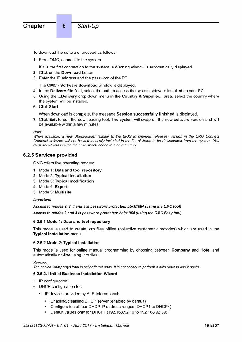
To download the software, proceed as follows:
1. From OMC, connect to the system.
If it is the first connection to the system, a Warning window is automatically displayed.2. Click on the Download button.3. Enter the IP address and the password of the PC.
The OMC - Software download window is displayed.4. In the Delivery file field, select the path to access the system software installed on your PC.5. Using the ...Delivery drop-down menu in the Country & Supplier... area, select the country where
the system will be installed.6. Click Start.
When download is complete, the message Session successfully finished is displayed.7. Click Exit to quit the downloading tool. The system will swap on the new software version and will
be available within a few minutes.
Note:When available, a new Uboot-loader (similar to the BIOS in previous releases) version in the OXO ConnectCompact software will not be automatically included in the list of items to be downloaded from the system. Youmust select and include the new Uboot-loader version manually.
6.2.5 Services providedOMC offers five operating modes:
1. Mode 1: Data and tool repository2. Mode 2: Typical installation3. Mode 3: Typical modification4. Mode 4: Expert5. Mode 5: Multisite
Important:
Access to modes 2, 3, 4 and 5 is password protected: pbxk1064 (using the OMC tool)
Access to modes 2 and 3 is password protected: help1954 (using the OMC Easy tool)
6.2.5.1 Mode 1: Data and tool repository
This mode is used to create .crp files offline (collective customer directories) which are used in theTypical Installation menu.
6.2.5.2 Mode 2: Typical installation
This mode is used for online manual programming by choosing between Company and Hotel andautomatically on-line using .crp files.
Remark:The choice Company/Hotel is only offered once. It is necessary to perform a cold reset to see it again.
6.2.5.2.1 Initial Business Installation Wizard
• IP configuration• DHCP configuration for:
• IP devices provided by ALE International:
• Enabling/disabling DHCP server (enabled by default)• Configuration of four DHCP IP address ranges (DHCP1 to DHCP4)• Default values only for DHCP1 (192.168.92.10 to 192.168.92.39)
Chapter 6 Start-Up
3EH21123USAA - Ed. 01 - April 2017 - Installation Manual 191/207

• Omniswitch:
• Enabling/disabling DHCP server (enabled by default)• Configuration of one single DHCP IP address range (default values: 192.168.92.5 to
192.168.92.9)• Default Numbering Plan• Installation number• Operating mode• Channels and Bundles• DECT ARI• Creation of DECT handsets• Metering• Date and time• Terminal List• Various Subscribers• Collective speed dial• OS groups• Call groups• Broadcast groups• Intercept groups• Screening
6.2.5.2.2 Initial Hotel Installation Wizard
As well as the Business configuration, this wizard can be used to configure terminal numbers in thehotel rooms.
6.2.5.2.3 Installation Wizard
This wizard enables you to use a .crp type file created under Data and tool repository -> InformationRepository Wizard.
Follow the instructions; if the data is accepted it is transmitted to the system which is then reset.
6.2.5.3 Mode 3: Typical modification
The 5 icons available in this mode (Terminals, Groups, System, Collective Directory and ExternalLines) are used to gain access to the wizards used to modify or configure simply various parameters asdetailed below.
The data will be taken into account by the system after clicking OK.
6.2.5.3.1 Subscribers
• List of subscribers: public number, name, discrimination level, accessible network line groups.• Dividing calls between normal mode and restricted mode.• EasyPlus View: detailed parameters for each subscriber: keys, languages, authorized usage,
personal code, callbacks, dynamic forwarding, personal directory, etc.
6.2.5.3.2 Groups
• OS Groups
• Making groups: introducing members into each group• Assigning a welcome message to each group
• Call Groups
• Name and type (parallel, cyclical or sequential)• Making groups: introducing members into each group
Chapter 6 Start-Up
3EH21123USAA - Ed. 01 - April 2017 - Installation Manual 192/207

• Assigning a welcome message to each group• BTS Clusters
• Name of each group• Making groups: introducing members into each group
• Call pick-up groups
Making groups: introducing members into each group
6.2.5.3.3 Collective Speed Dial
The name and destination number of the call for each entry.
6.2.5.3.4 System
• Default numbering plans
• Choose between national numbering plans or a 2, 3 or 4-digit star plan.• EasyPlus View: Normal service public numbering plan• EasyPlus View: Restricted service public numbering plan• EasyPlus View: Order codes• EasyPlus View: Internal numbering plan
• Installation numbers
• International code• National code• Installation number• EasyPlus View: Call back prefix• EasyPlus View: Customized caller number• EasyPlus View: Private installation number
• Metering
• Cost of telephone metering• EasyPlus View: Hotel metering cost for current currency unit (VAT, prepayment amount, etc.)• EasyPlus View: Metering options for current monetary unit• EasyPlus View: Print parameters• EasyPlus View: Metering options for replacement currency (Euro)
• Date and time• Software keys
• System Key• CTI Key
6.2.5.3.5 External Lines
• B-Channel number• External number for incoming calls (DISA)• Type of dialling
6.2.5.4 Mode 4: Expert
This mode cannot be accessed from OMCEasy.
This mode allows all modification and system maintenance. The wizards available in modes 2 and 3are also accessible.
Chapter 6 Start-Up
3EH21123USAA - Ed. 01 - April 2017 - Installation Manual 193/207

6.2.5.5 Mode 5: Multisite
This new mode is available with Easy, EasyPlus and Expert Views. It allows you to manage severalOXO Connect systems.
The Multisite feature includes the following basic services:
• An Installation Wizard to help installers and administrators to set up appropriate configurationswhen adding PBXs to a network.
• The automatic replication of data common to all networked PBXs. Common data is pushed from areference PBX to all other secondary PBXs in the network.
• The automatic synchronization of Phonebook names and phone numbers.
Note:The OMC Multisite feature is designed for setting up PBX networks from scratch. Large parts of the PBX settingsare overwritten when configured PBXs are added to a network.
Chapter 6 Start-Up
3EH21123USAA - Ed. 01 - April 2017 - Installation Manual 194/207

Chapter
7 Maintenance Level 1
This module provides maintenance advice on different hardware components of the OXO Connectsystem.
7.1 Battery MaintenanceOXO Connect systems (except the OXO Connect Compact) are supplied with internal batteries thatprovide back-up power in the event of a mains power failure. Alternatively, all systems may beoptionally equipped with an external battery pack to provide back-up power.
To guarantee system shutdown without data loss in the event of a mains power failure or if the mainsplug is unplugged from the wall socket, replace the batteries every two years. This maintenanceoperation is vital to guarantee sufficient power autonomy to allow the files to be saved before thesystem shuts down.
Before replacing batteries, the system must be powered down and the power cable removed from themains supply.
• To replace internal batteries, the rear panel of the system cabinet must be removed and the batterydrawer pulled out.
• To replace external batteries, the external battery box must be opened.
To maintain a good balance, replace all the batteries at the same time with batteries of thesame type, from the same manufacturer and from the same batch.
Make sure you respect the correct polarities when replacing batteries. There is a risk ofexplosion if the batteries are incorrectly replaced. Used batteries must be disposed ofaccording to the battery manufacturer's instructions.
The batteries are supplied uncharged. File saving in the event of a power failure can only beguaranteed once the batteries have been charged; that is, about 12 hours after turning on the system(PowerCPU EE switch in ON position).
7.1.1 Internal Battery Characteristics• number: 1 (OXO Connect S), 2 in parallel (OXO Connect M) or 3 in series (OXO Connect L)• sealed lead battery• 1,2 Ah / 12 V• fire resistance better than or equal to UL94-V2
7.1.2 External Battery Characteristics• number: up to 2 for OXO Connect Compact, up to 3 for OXO Connect S and OXO Connect M
platforms, up to 6 for OXO Connect L platforms• sealed lead battery• 7 Ah / 12 V• fire resistance better than or equal to UL94-V2
3EH21123USAA - Ed. 01 - April 2017 - Installation Manual 195/207
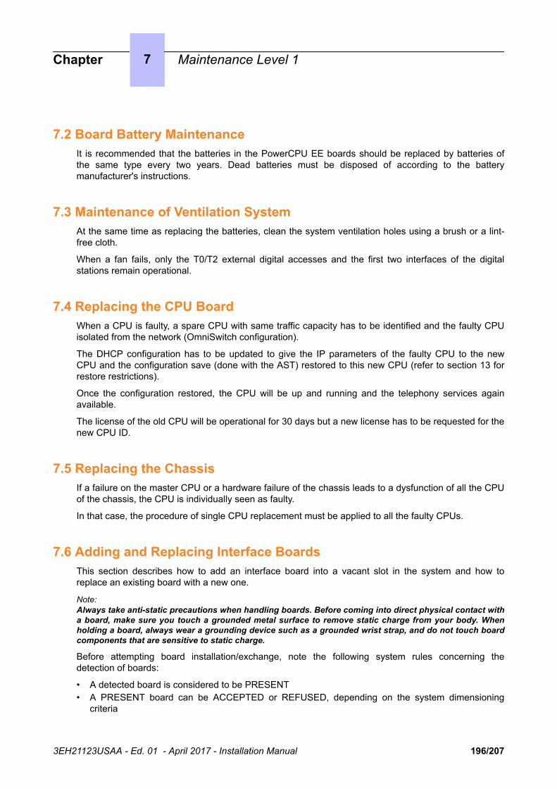
7.2 Board Battery MaintenanceIt is recommended that the batteries in the PowerCPU EE boards should be replaced by batteries ofthe same type every two years. Dead batteries must be disposed of according to the batterymanufacturer's instructions.
7.3 Maintenance of Ventilation SystemAt the same time as replacing the batteries, clean the system ventilation holes using a brush or a lint-free cloth.
When a fan fails, only the T0/T2 external digital accesses and the first two interfaces of the digitalstations remain operational.
7.4 Replacing the CPU BoardWhen a CPU is faulty, a spare CPU with same traffic capacity has to be identified and the faulty CPUisolated from the network (OmniSwitch configuration).
The DHCP configuration has to be updated to give the IP parameters of the faulty CPU to the newCPU and the configuration save (done with the AST) restored to this new CPU (refer to section 13 forrestore restrictions).
Once the configuration restored, the CPU will be up and running and the telephony services againavailable.
The license of the old CPU will be operational for 30 days but a new license has to be requested for thenew CPU ID.
7.5 Replacing the ChassisIf a failure on the master CPU or a hardware failure of the chassis leads to a dysfunction of all the CPUof the chassis, the CPU is individually seen as faulty.
In that case, the procedure of single CPU replacement must be applied to all the faulty CPUs.
7.6 Adding and Replacing Interface BoardsThis section describes how to add an interface board into a vacant slot in the system and how toreplace an existing board with a new one.
Note:Always take anti-static precautions when handling boards. Before coming into direct physical contact witha board, make sure you touch a grounded metal surface to remove static charge from your body. Whenholding a board, always wear a grounding device such as a grounded wrist strap, and do not touch boardcomponents that are sensitive to static charge.
Before attempting board installation/exchange, note the following system rules concerning thedetection of boards:
• A detected board is considered to be PRESENT• A PRESENT board can be ACCEPTED or REFUSED, depending on the system dimensioning
criteria
Chapter 7 Maintenance Level 1
3EH21123USAA - Ed. 01 - April 2017 - Installation Manual 196/207

• On a cold reset, all PRESENT boards are taken into account (irrespective of whether they areACCEPTED or REFUSED)
• A board which is PRESENT on a cold reset can later be determined as ABSENT on a warm reset ifin the meantime the board has been unplugged or there has been a board detection failure
• After a cold or warm reset, new boards are always taken into account and declared as PRESENT(and then ACCEPTED or REFUSED)
The following table describes situations more specifically relevant to plugging/unplugging boards.
Situation Description
A board is plugged into a slot never before oc-cupied
The board is detected as PRESENT and then deter-mined to be ACCEPTED or REFUSED (according toconfiguration criteria, such as authorized positionsand maximum hardware capacity). If the board is ac-cepted, its accesses are taken into account depend-ing on the system dimensioning criteria.
A board is replaced with another board of thesame type
A board is replaced with another board of a dif-ferent type
As above, except when the replacement board isplugged in, configuration data for the previous boardis cleared.
A PRESENT and ACCEPTED board is unplug-ged
The board's disappearance is detected and theboard is considered as out of order and then AB-SENT. However, configuration data associated withthe unplugged board remains available.
A PRESENT and REFUSED board is unplug-ged
The board's disappearance is detected and theboard is considered as ABSENT. However, configu-ration data associated with the unplugged board re-mains available.
7.6.1 Adding a board into a vacant slotThe procedure presented below assumes that a board is to be installed in a vacant slot in the systemcabinet.
Note:Hot installation is forbidden in OXO Connect Compact platforms. It is also forbidden for PowerCPU EEboards in all platforms.
1. If a hot installation is not possible, stop the system and disconnect it from the mains power supply.2. Locate the required vacant slot in the cabinet and remove the metal plate for this slot.3. Taking anti-static precautions (for example, by wearing a grounded wrist strap), pick up the new
board and plug it into the vacant slot.4. Secure the end-plate of the board to the cabinet with the screw provided.5. If you have stopped and powered down the system, reconnect it to the mains power supply and
restart it.6. Perform any configuration and/or tests required for the new board.
Note:Following configuration in the OMC tool, you may be required to perform a warm reset of the system for theconfiguration changes to take effect. In this case, the software will prompt you to perform the warm reset.
Chapter 7 Maintenance Level 1
3EH21123USAA - Ed. 01 - April 2017 - Installation Manual 197/207

7.6.2 Replacing an existing boardThe procedure presented below assumes that an existing board is to be removed from the system anda replacement board (of the same or different type) is to be installed in the same slot in the systemcabinet.
Note:Hot swap is forbidden in OXO Connect Compact. It is also forbidden for PowerCPU EE boards in allsystems.
1. If a hot swap is not possible, stop the system and disconnect it from the mains power supply.2. Locate the existing board to be removed in the cabinet and unscrew the securing screw from its
end-plate.3. Taking anti-static precautions (for example, by wearing a grounded wrist strap), pull the board out of
its slot.4. Taking anti-static precautions, pick up the replacement board and plug it into the now vacant slot.5. Secure the end-plate of the board to the cabinet with the screw provided.6. If you have stopped and powered down the system, reconnect it to the mains power supply and
restart it.7. Perform any configuration and/or tests required for the replacement board.
Note:Following configuration in the OMC tool, you may be required to perform a warm reset of the system for theconfiguration changes to take effect. In this case, the software will prompt you to perform the warm reset.
7.7 MSDB replacementWhen the eMMC device is about to reach the end of its life, a history event (urgent alarm type) isupdated in the hardware anomaly table of OMC. In that case:
• If the existing MSDB is readable, MSDB must be replaced and migration must be done with thecustomer configuration/data using OMC and LoLa
• If the existing MSDB is not readable and the data are lost, MSDB must be replaced and LoLainstallation is required
The event 37: MSDB health status is generated once a week with the following error cases updated inthe comp info:
• Value 01 - Device has reached >= 80% of its life time due to increased block erase count• Value 02 - Device has reached > =90% of its life time due to increased block erase count• Value 03 - Device has reached >=80% of its life time due to increased bad block• Value 04 - Device has reached >=90% of its life time due to increased bad block
7.8 RAM replacementWhen a 256 MB RAM is installed on the PowerCPU EE, the history event 38: Unsupported RAM size(urgent alarm type) is updated in the hardware anomaly table of OMC at each initialization of thesystem.
In that case, the unsupported RAM must be replaced with the supported 512 MB RAM.
Chapter 7 Maintenance Level 1
3EH21123USAA - Ed. 01 - April 2017 - Installation Manual 198/207

Chapter
8 Glossary
8.1 AACD Automatic Call Distribution. A computerized phone system that responds to the caller with a
voice menu, and connects the call to the required agent. It can also control call flows byautomatically routing calls in the order of arrival.
ACSE Association Control Service Element. OSI convention used for establishing, maintaining andreleasing connections between two applications.
ADN Additional Designation Number.
AFU-1 Auxiliary Function Unit. Daughter board of the PowerCPU EE board supporting ancillaryfunctions such as general bell, doorphone, audio in, audio out, etc.
AMIX-1 Mixed analog equipment board: analog accesses with CLIP functionalities, analog and digitalterminal connection interfaces.
AP Access Point. A device that acts as a switch between the wireless LAN (802.11a, b, or g)and the wired LAN (802.3). There are two types of APs: Thin and Fat. The newer Thintechnology AP consists of a thin AP and an access controller (also known as a wirelesscontroller). Only the time-critical functions are managed by the thin AP. The other featuresare managed by the access controller.
APA Analog Public Access. Board allowing the connection of analog network lines (switchednetwork) with CLIP functionality. That board, equipped with GSCLI boards (Ground Start), iscompatible with the American public network.
API Application Programming Interface
ARI Access Right Identifier. System identification number (DECT feature).
ARS Automatic Route Selection. A logic direction is a set of trunks used for a call with thefollowing facilities: seeking out the optimal path for a call, using the least-cost operator ornetwork; overflow management: enables a PCX to find a new route to make an outgoing callwhen there are no resources available in the initial trunk.
ASN-1 Abstract Syntax Notation 1. OSI language for describing data types independently ofprocessor structures and technical representations.
ATA Analog Trunk Access. Board for connecting analog network lines (switched network).
8.2 BBACKGROUNDMUSIC
External device (e.g. radio tuner) that can broadcast music over theloudspeakers of idle terminals; broadcasting is stopped automatically if there isan incoming call to the terminal or if the user makes a call.
BACP Bandwidth Allocation Control Protocol. Control protocol associated with BAP.
BAP Bandwidth Allocation Protocol. PPP protocol that manages bandwidth byallocating it dynamically between two ports, i.e. between the two extremities ofa point-to-point link.
BOD Bandwidth On Demand. Service that allocates bandwidth automatically inresponse to traffic volume.
3EH21123USAA - Ed. 01 - April 2017 - Installation Manual 199/207

BRA Basic Rate Access. Board for connecting T0 or DLT0 digital basic accesses;each access supports a data rate of 144 kbps, structured as 2 B-channels at64 kbps for voice and data transmission, and 1 D-channel at 16 kbps forsignaling.
BTCO Build To Customer Order.
8.3 CCA Certificate Authority.
CCP Compression Control Protocol.
CHAP Challenge-Handshake Authentication Protocol. Security function supported onconnections that use PPP encapsulation: prevents unauthorized access.
CIFS Common Internet File System. This protocol is an extension to the SMB file sharingsystem. Its main benefit is to provide compatibility with locking operations and multipleSMB read/write operations.
CLIP Calling Line Identification Presentation. Complementary service for digital protocols thatallows the caller number to be presented to the called party.
CLIR/COLR
Calling/COnnected Line Identification Restriction. Service that inhibits CLIP or COLP.
CNIP Calling Name Identification Presentation. Complementary service for private digitalprotocols (ISVPN or ABC-F) that allows the caller's name to be presented to the calledparty.
COLP COnnected Line identification Presentation. Complementary service for digital protocolsthat allows the number of the connected user (the one who answers the call) to bepresented to the caller.
CONP COnnected Name identification Presentation. Complementary service for private digitalprotocols (ISVPN or ABC-F) that allows the name of the connected user (the one whoanswers the call) to be presented to the caller.
CPU Central Processing Unit. Term designating the processor or microprocessor. The centralprocessing unit executes computer program instructions.
CSTA Computer Supported Telephony Application. ECMA standard that defines commandexchanges between a PCX and a server.
CTI Computer-Telephone Integration. Interaction mechanism between 2 sections, namely adata processing section (computer) and a telecommunications section (PCX),independently of the physical layout of the 2 sections.
CTL Certificates Trust List.
8.4 DDAP DECT Access Point
DASS2 Digital Access Signaling Specification number 2
DDI Direct Dialing In. Direct external call number for the system terminals (depending on theconfiguration with the public network operator).
Chapter 8 Glossary
3EH21123USAA - Ed. 01 - April 2017 - Installation Manual 200/207
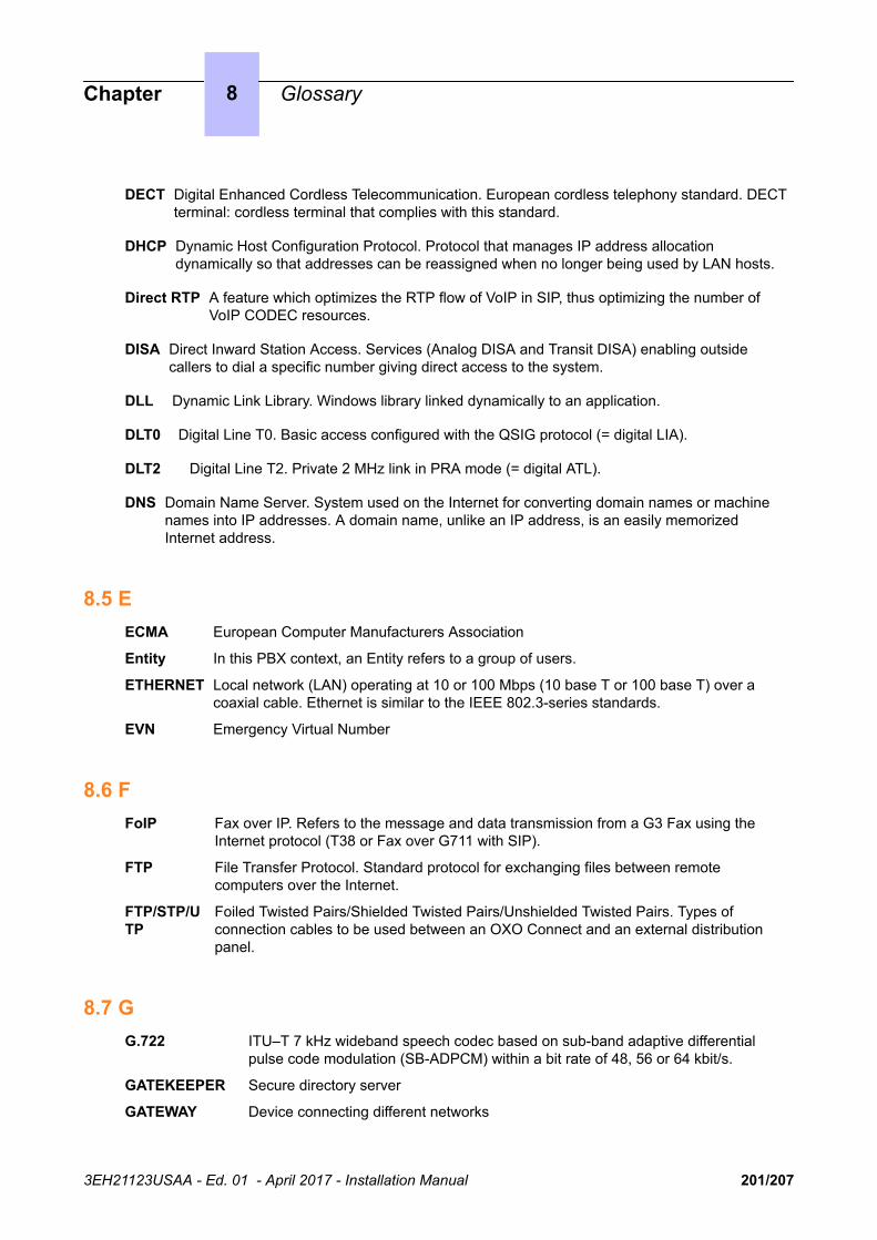
DECT Digital Enhanced Cordless Telecommunication. European cordless telephony standard. DECTterminal: cordless terminal that complies with this standard.
DHCP Dynamic Host Configuration Protocol. Protocol that manages IP address allocationdynamically so that addresses can be reassigned when no longer being used by LAN hosts.
Direct RTP A feature which optimizes the RTP flow of VoIP in SIP, thus optimizing the number ofVoIP CODEC resources.
DISA Direct Inward Station Access. Services (Analog DISA and Transit DISA) enabling outsidecallers to dial a specific number giving direct access to the system.
DLL Dynamic Link Library. Windows library linked dynamically to an application.
DLT0 Digital Line T0. Basic access configured with the QSIG protocol (= digital LIA).
DLT2 Digital Line T2. Private 2 MHz link in PRA mode (= digital ATL).
DNS Domain Name Server. System used on the Internet for converting domain names or machinenames into IP addresses. A domain name, unlike an IP address, is an easily memorizedInternet address.
8.5 EECMA European Computer Manufacturers Association
Entity In this PBX context, an Entity refers to a group of users.
ETHERNET Local network (LAN) operating at 10 or 100 Mbps (10 base T or 100 base T) over acoaxial cable. Ethernet is similar to the IEEE 802.3-series standards.
EVN Emergency Virtual Number
8.6 FFoIP Fax over IP. Refers to the message and data transmission from a G3 Fax using the
Internet protocol (T38 or Fax over G711 with SIP).
FTP File Transfer Protocol. Standard protocol for exchanging files between remotecomputers over the Internet.
FTP/STP/UTP
Foiled Twisted Pairs/Shielded Twisted Pairs/Unshielded Twisted Pairs. Types ofconnection cables to be used between an OXO Connect and an external distributionpanel.
8.7 GG.722 ITU–T 7 kHz wideband speech codec based on sub-band adaptive differential
pulse code modulation (SB-ADPCM) within a bit rate of 48, 56 or 64 kbit/s.
GATEKEEPER Secure directory server
GATEWAY Device connecting different networks
Chapter 8 Glossary
3EH21123USAA - Ed. 01 - April 2017 - Installation Manual 201/207

GENERAL BELL If the operator is absent, internal and external calls to the operator are directed toan external signaling device that lets any authorized terminal take these calls.
8.8 HH.323 ITU standard for multimedia communication (voice, video, data).
H.450 Additional services associated with H.323 version 2.
HSL High Speed Link. Link between the basic module and a module expansion; requires an HSLdaughter board to be fitted on the PowerCPU EE and PowerMEX boards.
HTTP HyperText Transfer Protocol. Standard application protocol for exchanging files (text, images,audio, video, etc.) over the Internet.
HTTPS Secure HyperText Transfer Protocol. Secure version of HTTP: encrypts and decrypts pagescontaining user requests as well as pages retrieved from a web server.
8.9 IIAP Internet Access Provider. See ISP.
IBS Intelligent Base Station. There are 2 kinds of IBSs: one that can be installed indoors, oneoutdoors.
ICMP Internet Control Message Protocol. Network protocol that provides error reports andinformation on the processing of IP packets.
IM Instant Messaging
IMAP4 Internet Message Access Protocol. A protocol of the same type as POP3, the differencebeing that the messages always stay on the ISP server, even after consultation. IMAPrequires continuous access to the server while the messaging service is in use.
IN Installation Number
IP Internet Protocol. The main protocol supporting the Internet. IP governs the forwardingand transmission of data packets over supporting multivendor packet-switched networks.
IP-DECT Wireless communication which uses VoIP between the server and the base station andthe DECT air interface between the base station and the mobile handsets.
IPSec Internet Protocol Security. Standard taking network security into account. Protocol used inthe implementation of VPNs, and for remote access by connection to a VPN.
ISDN Integrated Services Digital Network. Standard for the transmission of digital data overtelephone cables or other communication vectors.
ISDN-EFM Integrated Services Digital Network- Emergency Forwarding Module. T0/S0 ForwardingModule.
ISP Internet Service Provider. Internet Access Provider. A company that provides Internetaccess for individuals and companies, along with other services, such as web siteconstruction and hosting.
ISVPN Integrated Services Virtual Private Network. Protocol used in a private virtual digitalnetwork; it offers functions such as transfer optimization and the transmission ofinformation such as the name, busy status or diversions.
ISVPN+ Includes metering information in addition to the usual ISVPN services.
Chapter 8 Glossary
3EH21123USAA - Ed. 01 - April 2017 - Installation Manual 202/207

ITU International Telecommunications Union : global coordination body.
IVPS Virtual card, embedded on the CPU board, supporting a voice mail application.
8.10 KKEY SYSTEM(mode)
Dedicated terminal operating mode in which the terminal features as manyresource keys (RSP) as there are network lines in the system.
8.11 LLAN Local Area Network. Network of interconnected switches, routers, and servers that
share the resources of a processor or server in a relatively restricted geographicalarea, usually the premises of a company. In the context of the OXO Connect, theLAN includes an IP network and provides services to the wired client and to theWLAN client: file server, proxy, main server.
LDAP Lightweight Directory Access Protocol for access to directory services managed bya directory server.
LOUDSPEAKER External loudspeaker used for broadcasting messages.
8.12 MMANAGER/SECRETARY
Set of specific services (profile, filtering, diversion) between a manager terminaland a secretary terminal.
MIX Mixed equipment board: T0 accesses, analog and digital terminal connectioninterfaces.
MLAA Multiple Automated Attendant: Software component used for automatic incomingcalls routing via voice guides.
MMC Man Machine Configuration. Command lines that a user types to the interface ofan application to change the parameters of system elements. It can also be inthe form of graphic images that the user can select to make changes.
MPPP Multi-link PPP. A protocol that aggregates bandwidth from a number of links toobtain faster communication speeds.
MULTILINETERMINAL
Terminal that has several lines for managing several calls at the same time.
8.13 NNAT Network Address Translation. A service that converts the IP address used on one network into
another IP address recognizable by another network. Address translation allows companies tokeep their own private IP addresses for internal purposes, while using just one IP address forexternal communication.
NMC Network Management Center. Workstation allowing a communication server administrator toremotely manage, administer (storage of call metering tickets for example) and optimize oneor more OXO Connect systems.
Chapter 8 Glossary
3EH21123USAA - Ed. 01 - April 2017 - Installation Manual 203/207

NMT Numbering Modification Table
NNTP Network News Transfer Protocol. Protocol used by computers to handle messages created inUsenet forums.
8.14 OODC On Demand Communication - Commercial name of On Demand mode.
On Demandmode
This licence mode introduces a “user” definition and the validity of the license inOPEN state is limited and daily checked by the system.
OS Operator Station. Dedicated terminal for answering incoming calls from the publicnetwork.
OMC OXO Connect Management Console (formerly PM5). A PC-based managementand configuration tool.
8.15 PPAP Password Authentication Procedure. Procedure used by PPP servers to validate
connection requests.
PASSWORD Code acting as a password, controlling access to the voice mail unit and theterminal locking function.
PAT Port Address Translation
PCBT PC Based Telephony
PCX (mode) Mode of operation of dedicated terminals; in this mode, all the network lines arematerialized by general-purpose resource keys (RSB).
PE Public Exchange. Public central terminal (switch).
PLEASE WAITMESSAGE
An audio component of the system (or an external device, such as a cassetteplayer) which plays a message or piece of music while keeping an externalcorrespondent on hold.
POP3 Post Office Protocol. Standard Internet protocol for receiving electronicmessages. POP3 is a client/server protocol in which the messages are receivedand hosted by the ISP. When a message is read, it is transferred to the clientterminal and is no longer hosted by the ISP.
PowerMEX Module expansion. Controller board for extension or module expansion.
PPP Point-to-Point Protocol. Protocol used in communication between two computersusing a serial interface (typically a PC connected to a server via a telephoneline).
PRA Primary Rate Access. Board for connecting a T2 digital primary access; theaccess supports 48 kbps structured as 30 B-channels at 64 kbps for voice anddata transmission, and 1 D-channel at 64 kbps for signaling.
PROXY A proxy server is used as an interface between a user and the external Internetnetwork.
PSAP Safety Access Point
PSTN Public Switched Telephone Network.
Chapter 8 Glossary
3EH21123USAA - Ed. 01 - April 2017 - Installation Manual 204/207

PTN(X) Private Telecommunications Network (eXchange). A private network consisting ofswitches and terminals connected together by telephone links.
PWT Personal Wireless Telecommunications. Corresponds to the DECT standard forthe North American countries (especially the US).
8.16 QQOS Quality Of Service. Network characteristics (transmission speed, etc.) can be measured,
improved and, to some extent, guaranteed in advance.
QSIG Q Signaling Protocol. Set of standard signaling protocols between the private PBXs of atelephone network (Q reference point) interconnected by digital ATLs.
8.17 RRADIUS Remote Authentication Dial-In User Service. A client/server protocol that enables
remote access servers to communicate with a central server in order to authenticateremote users before allowing them access to the systems or services they haverequested.
RAS Remote Access Server. Remote access server to the system LAN.
RCE Rich Communication Edition (for example, OXO Connect Compact is the shortdesignation for OXO Connect Compact).
RGO, RGI,RGM
General resource keys supporting local and/or external calls, whether outgoing(RGO), incoming (RGI), or mixed (RGM).
RNIS "Réseau Numérique à Intégration de Services". French equivalent of ISDN.
ROSE Remote Operations Service Element
RSB Resource key dedicated to a trunk group (bundle); used for making external outgoingcalls on a particular trunk group, and receiving all network calls.
RSD Resource key for a particular destination; supports local calls for this number ifassigned to a speed dial number, incoming calls for the number if assigned to a DDInumber, or outgoing calls on a trunk group if assigned to a trunk group.
RSL Resource key dedicated to a set; supports calls to and from a particular set.
8.18 SSATA Serial Advanced Technology Attachment - Hard disk interface bus.
S0 BUS Type of connection for S0 digital terminals (passive short bus, long/short point-to-point bus,extended bus); S0 buses and terminals are connected up via an S0 option embedded in anAlcatel Reflexes terminal.
SELV Safety Extra Low Voltage. Classification of interfaces in accordance with standardsEN60950 and IEC 950.
SIP Session Initiation Protocol. A signaling protocol for Internet conferencing, telephony, eventsnotification, and instant messaging. SIP initiates for example, call setup, routing andauthentication within an IP domain.
Chapter 8 Glossary
3EH21123USAA - Ed. 01 - April 2017 - Installation Manual 205/207
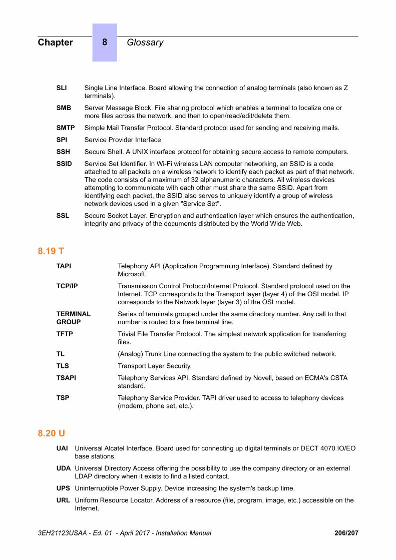
SLI Single Line Interface. Board allowing the connection of analog terminals (also known as Zterminals).
SMB Server Message Block. File sharing protocol which enables a terminal to localize one ormore files across the network, and then to open/read/edit/delete them.
SMTP Simple Mail Transfer Protocol. Standard protocol used for sending and receiving mails.
SPI Service Provider Interface
SSH Secure Shell. A UNIX interface protocol for obtaining secure access to remote computers.
SSID Service Set Identifier. In Wi-Fi wireless LAN computer networking, an SSID is a codeattached to all packets on a wireless network to identify each packet as part of that network.The code consists of a maximum of 32 alphanumeric characters. All wireless devicesattempting to communicate with each other must share the same SSID. Apart fromidentifying each packet, the SSID also serves to uniquely identify a group of wirelessnetwork devices used in a given "Service Set".
SSL Secure Socket Layer. Encryption and authentication layer which ensures the authentication,integrity and privacy of the documents distributed by the World Wide Web.
8.19 TTAPI Telephony API (Application Programming Interface). Standard defined by
Microsoft.
TCP/IP Transmission Control Protocol/Internet Protocol. Standard protocol used on theInternet. TCP corresponds to the Transport layer (layer 4) of the OSI model. IPcorresponds to the Network layer (layer 3) of the OSI model.
TERMINALGROUP
Series of terminals grouped under the same directory number. Any call to thatnumber is routed to a free terminal line.
TFTP Trivial File Transfer Protocol. The simplest network application for transferringfiles.
TL (Analog) Trunk Line connecting the system to the public switched network.
TLS Transport Layer Security.
TSAPI Telephony Services API. Standard defined by Novell, based on ECMA's CSTAstandard.
TSP Telephony Service Provider. TAPI driver used to access to telephony devices(modem, phone set, etc.).
8.20 UUAI Universal Alcatel Interface. Board used for connecting up digital terminals or DECT 4070 IO/EO
base stations.
UDA Universal Directory Access offering the possibility to use the company directory or an externalLDAP directory when it exists to find a listed contact.
UPS Uninterruptible Power Supply. Device increasing the system's backup time.
URL Uniform Resource Locator. Address of a resource (file, program, image, etc.) accessible on theInternet.
Chapter 8 Glossary
3EH21123USAA - Ed. 01 - April 2017 - Installation Manual 206/207

UUS User to User Signaling. Information carried clear end-to-end by ISDN to enable exchangesbetween network subscribers; the ISVPN protocol is contained within this information.
8.21 VVMU Voice Mail Unit. The integrated voice server provides a voice mailbox for each user, as well
as a general voice mailbox and features such as Personal Assistant, Automatic Attendantand Audiotex.
VoIP Voice over IP. Term designating voice transmission over a data network using the Internetprotocol.
VoWLAN Voice over WLAN. Term designating voice transmission over a data network using theWLAN.
VPN Virtual Private Network. Private data network that uses the public telecommunicationsinfrastructure (e.g. the Internet) while maintaining confidentiality by means of tunnelingprotocols and security procedures.
8.22 WWAN Wide Area Network. A geographically dispersed telecommunications network. The
term WAN is used in contrast to LAN.
WIFI Wireless Fidelity.
WINS Windows Internet Naming Service. In Windows environment, the service thatmanages the correspondence between client station names and LAN locationsrelative to their IP addresses.
WLAN Wireless Local Area Network. A LAN that provides networking using radiofrequencies rather than wires for communication.
WLANassociation
An association refers to the connection between the WLAN client and the AP. Thereare two types of associations: passive scanning and active scanning. In passivescanning, APs send out information such as SSIDs and supported rates, while theclient passively scans the radio channels for beacons and probe responses. Theclient then selects an AP. The client keeps scanning even after the association ismade (to support roaming). In active scanning, clients send out probe requests. Ifthe probe request contains an SSID, only the APs with the correct SSID willrespond. If the probe request contains a broadcast, all the APs will respond.
WLAN client Any PC, PDA, or phone set that supports the 802.11a and 802.11b/g protocols canbe a WLAN client.
WLANhandset
A wireless terminal that is connected to the system through a wired Access Point(AP). The radio connection between the wireless terminal and the AP is specified bythe 802.11 family of specifications. The WLAN handset range includes Alcatel-Lucent OmniTouch 8118/8128 WLAN Handsets. WLAN handsets are sometimesreferred to as MIPT (Mobile IP Touch) handsets.
Chapter 8 Glossary
3EH21123USAA - Ed. 01 - April 2017 - Installation Manual 207/207