refrigeration and cryogenics
DESCRIPTION
Refrigeration and cryogenicsTRANSCRIPT
Refrigeration and Refrigeration and cryogenicscryogenics
Zakład Kriogeniki i Technologii GazowychZakład Kriogeniki i Technologii Gazowych
Dr hab. inż. Maciej Chorowski, prof. PWrDr hab. inż. Maciej Chorowski, prof. PWr

Methods of lowering the Methods of lowering the temperaturetemperature
Isentropic expansionIsentropic expansion Joule-Thomson expansionJoule-Thomson expansion Free expansion – gas exhaust Free expansion – gas exhaust
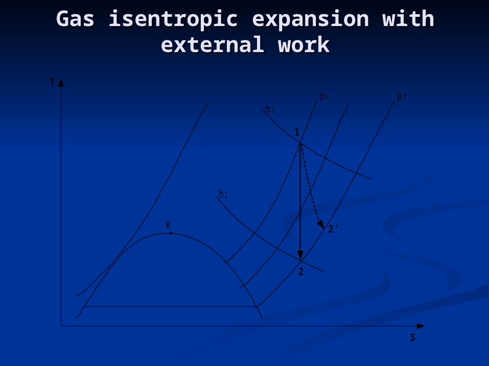
Gas isentropic expansionGas isentropic expansion with with external workexternal work
K
p 1 p 2
h 1
h 2
1
2
T
S
2'
Gas isentropic expansionGas isentropic expansion with with external workexternal work
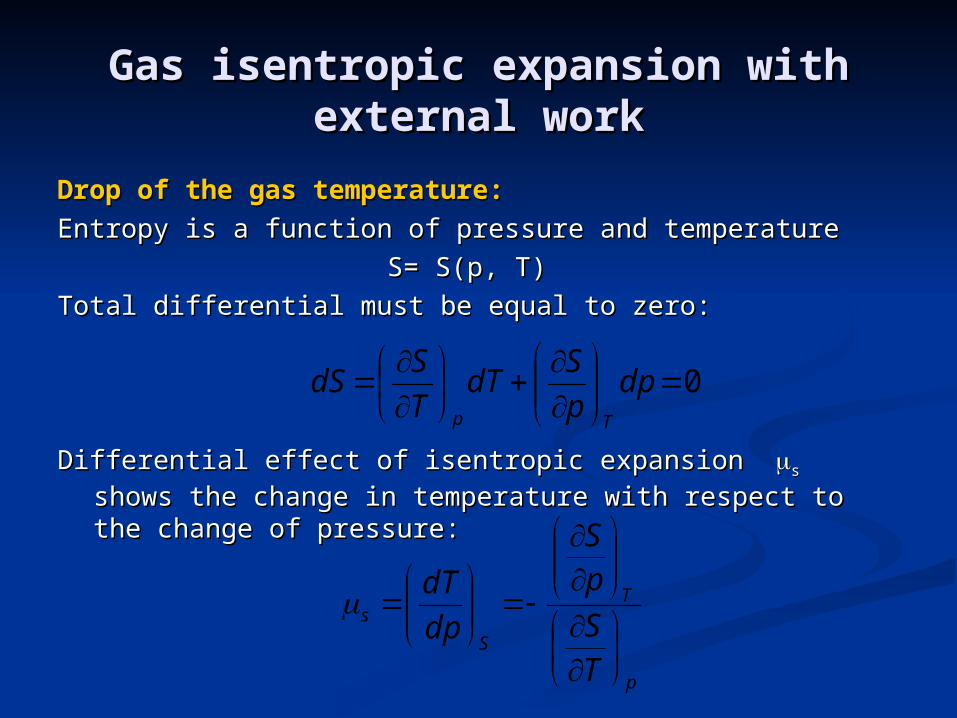
Drop of the gas temperature:Drop of the gas temperature:
Entropy is a function of pressure and temperatureEntropy is a function of pressure and temperature
S= S(p, T)S= S(p, T)
Total differential must be equal to zero:Total differential must be equal to zero:
Differential effect of isentropic expansion Differential effect of isentropic expansion ss shows the shows the change in temperature with respect to the change of change in temperature with respect to the change of pressure:pressure:
0
dpp
SdT
T
SdS
Tp
p
T
S
s
TS
pS
dp
dT

Gas isentropic expansionGas isentropic expansion with with external workexternal work
We know from thermodynamicsWe know from thermodynamics
We getWe get
where: where: is coefficient of cubical expansionis coefficient of cubical expansion
pTT
v
p
S
T
cp
T
S
p
cp
T
cp
Tv
T
dp
dT p
S
s
pT
1
Gas isentropic expansionGas isentropic expansion with with external workexternal work
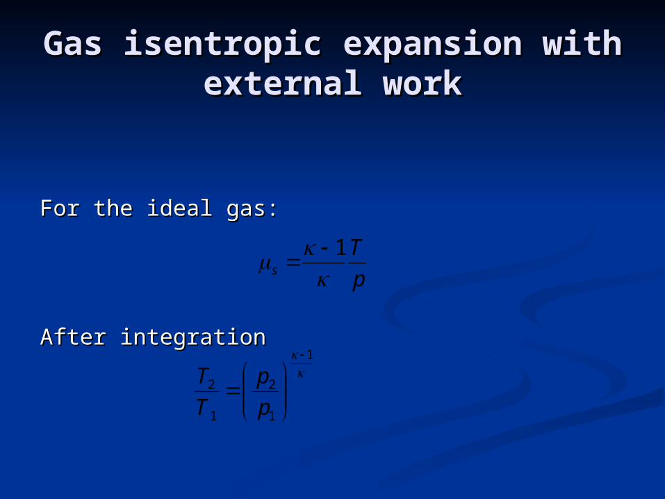
For the ideal gas:For the ideal gas:
After integrationAfter integration
p
Ts
1
1
1
2
1
2
p
p
T
T

Piston expanderPiston expander
G A Z G A Z
p 1, T 1, h 1 p 2, T 2, h 2
1
2
3 4
5
6p 1 p 2
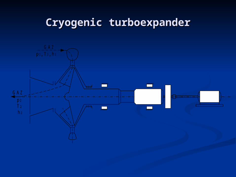
Cryogenic turboexpanderCryogenic turboexpander
G A Z
G A Z
p 1, T 1, h 1
p 2
T 2
h 2

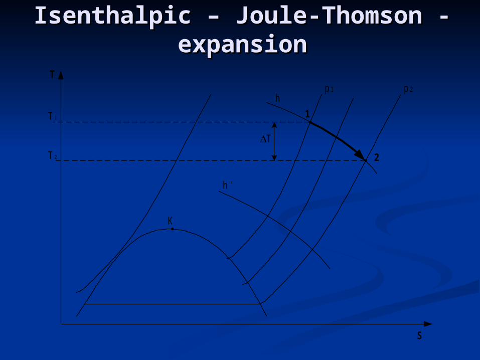
Isenthalpic Isenthalpic – Joule-Thomson - – Joule-Thomson - expansionexpansion
When gas, vapour or liquid expands adiabatically in an open system without doing any external work, and there is no increment in velocity on the system reference surface, the process is referred to as throttle expansion.
In practice, this process is implemented by installing in the gas stream some hydraulic resistance such as throttling valve, gate, calibrated orifice, capillary, and so on.
p 1
1 2
w 1 w 2
p
p 2
21121221
2221 2
1 lhhzzgwwq
Isenthalpic Isenthalpic – Joule-Thomson - – Joule-Thomson - expansionexpansion
K
p 1 p 2
h
h '
1
2
T
S
T 1
T 2
T

Temperature drop inTemperature drop in Isenthalpic Isenthalpic – Joule-Thomson - – Joule-Thomson - expansionexpansion
Enthalpy is a function of pressure and temperature:Enthalpy is a function of pressure and temperature:
h= h(p, T)h= h(p, T)
Total differential must be equal to zero:Total differential must be equal to zero:
Differential throttling effect μDifferential throttling effect μhh::
Isenthalpic Isenthalpic – Joule-Thomson - – Joule-Thomson - expansionexpansion
dTt
hdp
p
hdh
pT
p
T
h
h
T
h
p
h
dp
dT

Isenthalpic Isenthalpic – Joule-Thomson - – Joule-Thomson - expansionexpansion
p, MPa
100,0
50,0
25,0
10,0
5,0
1,0
0,5
3
2,5
T, K5 10 25 50 100 250 500 1000
H e
H 2
N e
Ar
N 2
pow ietrze
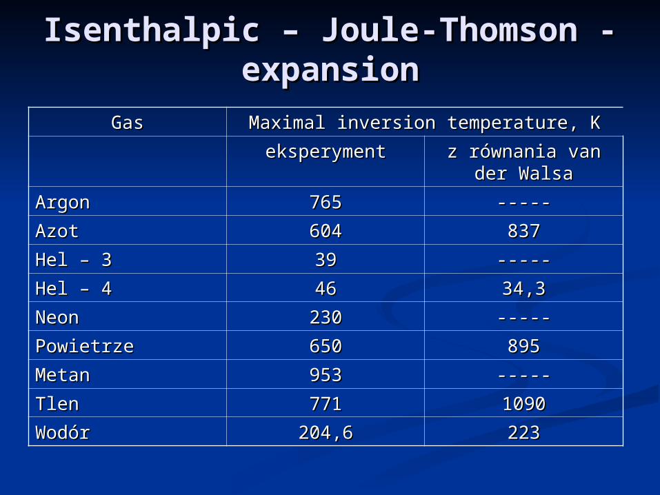
Isenthalpic Isenthalpic – Joule-Thomson - – Joule-Thomson - expansionexpansion
GasGas Maximal inversion temperature, KMaximal inversion temperature, K
eksperymenteksperyment z równania van der z równania van der WalsaWalsa
ArgonArgon 765765 ----------
AzotAzot 604604 837837
Hel – 3 Hel – 3 3939 ----------
Hel – 4 Hel – 4 4646 34,334,3
NeonNeon 230230 ----------
PowietrzePowietrze 650650 895895
MetanMetan 953953 ----------
TlenTlen 771771 10901090
WodórWodór 204,6204,6 223223

Free expansion (exhaust)Free expansion (exhaust)
p f
p f
p f
p f
T 0,p 0
V 0
V 1
V 2

1.1. Adiabatic processAdiabatic process
2.2. Non equilibrium process – gas Non equilibrium process – gas pressure and external pressure are pressure and external pressure are not the same not the same
3.3. Constant external pressure (pConstant external pressure (pff= = const.)const.)
4.4. External work against pressure pExternal work against pressure pff
Free expansion (exhaust)Free expansion (exhaust)

Final gas temperature:Final gas temperature:I Law of ThermodynamicsI Law of Thermodynamics
where:where:uu00, u, uf f – initial and final gas internal – initial and final gas internal
energyenergyvv00, v, vf f – initial and final gas volume– initial and final gas volume
Free expansion (exhaust)Free expansion (exhaust)
)( 00 vvpuu fff
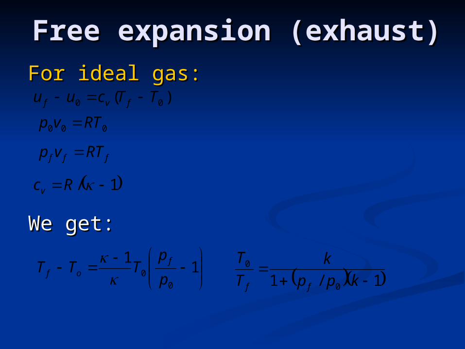
For ideal gas:For ideal gas:
We get:We get:
Free expansion (exhaust)Free expansion (exhaust)
)( 00 TTcuu fvf
000 RTvp
fff RTvp
1/ Rcv
1
1
00 p
pTTT f
of
1/1 0
0
kpp
k
T
T
ff

Comparison of the Comparison of the processes for airprocesses for air

Cryogenic gas Cryogenic gas refrigeratorsrefrigerators

Heat exchangersHeat exchangers
Recuperative Regenerative

Comparison of coolersComparison of coolers
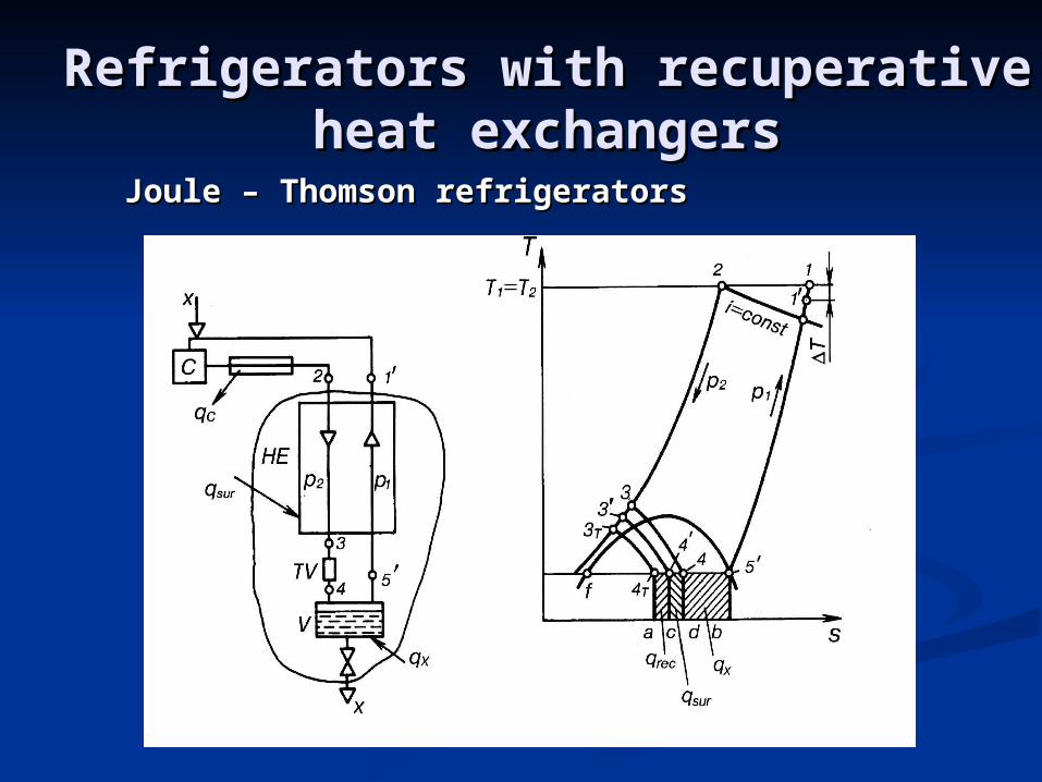
Refrigerators with recuperative Refrigerators with recuperative heat exchangersheat exchangers
Joule – ThomsonJoule – Thomson refrigeratorsrefrigerators

ExampleExampless of of miniature miniature Joule- Joule-Thomson refrigeratorThomson refrigerator

Claude refrigeratorsClaude refrigerators

Stirling coolersStirling coolers


Stirling coolerStirling cooler
Stirling coolerStirling cooler
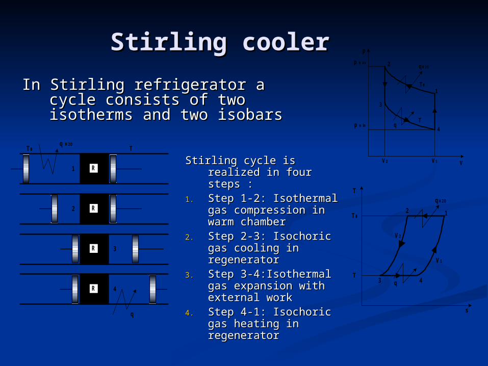
Stirling cycle is realized Stirling cycle is realized in four steps : in four steps :
1.1. Step 1-2: Isothermal Step 1-2: Isothermal gas compression in gas compression in warm chamberwarm chamber
2.2. Step 2-3: Isochoric Step 2-3: Isochoric gas cooling in gas cooling in regenerator regenerator
3.3. Step 3-4:Isothermal Step 3-4:Isothermal gas expansion with gas expansion with external workexternal work
4.4. Step 4-1: Isochoric Step 4-1: Isochoric gas heating in gas heating in regeneratorregenerator
R
R
R
R
TT0q H2O
q
1
2
3
4
p
V
1
2
3
4
p m ax
p m in
V2 V1
T0
T
qH2O
q
T
T0
qH2O
q
T
V1
V2
12
3 4
s
In Stirling refrigerator a cycle In Stirling refrigerator a cycle consists of two isotherms and consists of two isotherms and two isobarstwo isobars
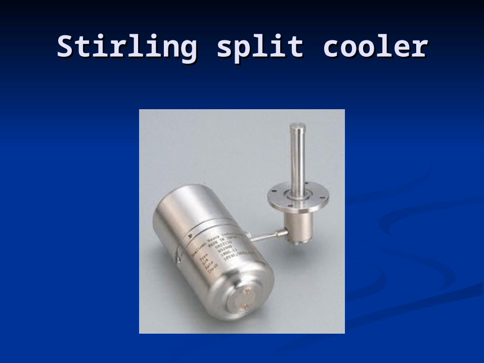
Stirling split coolerStirling split cooler

Stirling cooler with Stirling cooler with linear motorlinear motor

Efficiency of Stirling cooler Efficiency of Stirling cooler filled with ideal gasfilled with ideal gas
TT
T
ll
q
ecStr
0
1
2lnd2
1v
vRT
v
vRTl o
v
v
oc Work of isothermal compression
2
1lnd1
2v
vRT
v
vRTl
v
v
e Work of isothermal expansion
1
2lnv
vRTq
Heat of isothermal expansion

Stirling cooler configuration:Stirling cooler configuration:
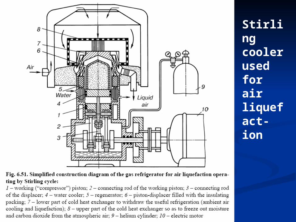
Stirling cooler used for air liquefact-ion

Stirling cooler used for air Stirling cooler used for air liquefactionliquefaction

Two stage Stirling Two stage Stirling refrigeratorrefrigerator

Gifforda – McMahon coolerGifforda – McMahon cooler

Four steps of McMahon cycle:Four steps of McMahon cycle:
1.1. Filling . Filling .
2.2. Gas displacement Gas displacement
3.3. Free exhaust of the gas Free exhaust of the gas
4.4. Discharge of cold chamberDischarge of cold chamber
Efficiency of McMahon coolerEfficiency of McMahon cooler::
Gifforda – McMahon coolerGifforda – McMahon cooler
2121
21
/ln/
1/
ppTppT
ppT
oMG

McMahon refrigeratorMcMahon refrigerator
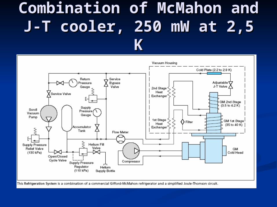
Combination of McMahon Combination of McMahon and J-T cooler, 250 mW at and J-T cooler, 250 mW at
2,5 K2,5 K

Pulse tube – free exhaustPulse tube – free exhaust
p f
p f
p f
p f
T 0,p 0
V 0
V 1
V 2
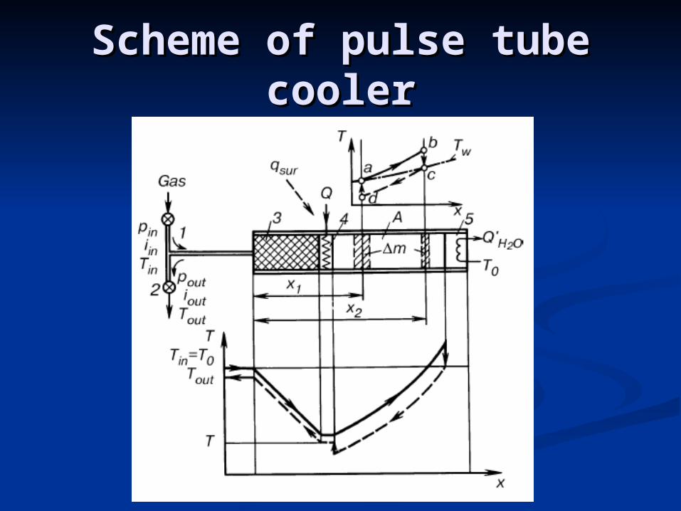
Scheme of pulse tube Scheme of pulse tube coolercooler

Development of pulse tube Development of pulse tube coolerscoolers
Gifford, 1963, rather curiosity that efficient cooler
Kittel, Radebaugh, 1983 orifice pulse tube
Dr. Zhu et. al., 1994, multiply by-pass pulse tube

Comparison of Stirling and Comparison of Stirling and orifice pulse tube coolerorifice pulse tube cooler

Pulse tube cooler for 77 K Pulse tube cooler for 77 K applicationsapplications
Weight:2.4 kgDimensions (l x w x h):11.4 x 11.4 x 22 cmCapacity:2.5W @ 65KUltimate low temperature:35KInput power2kW
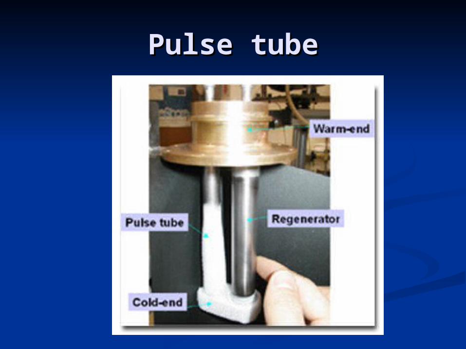
Pulse tubePulse tube
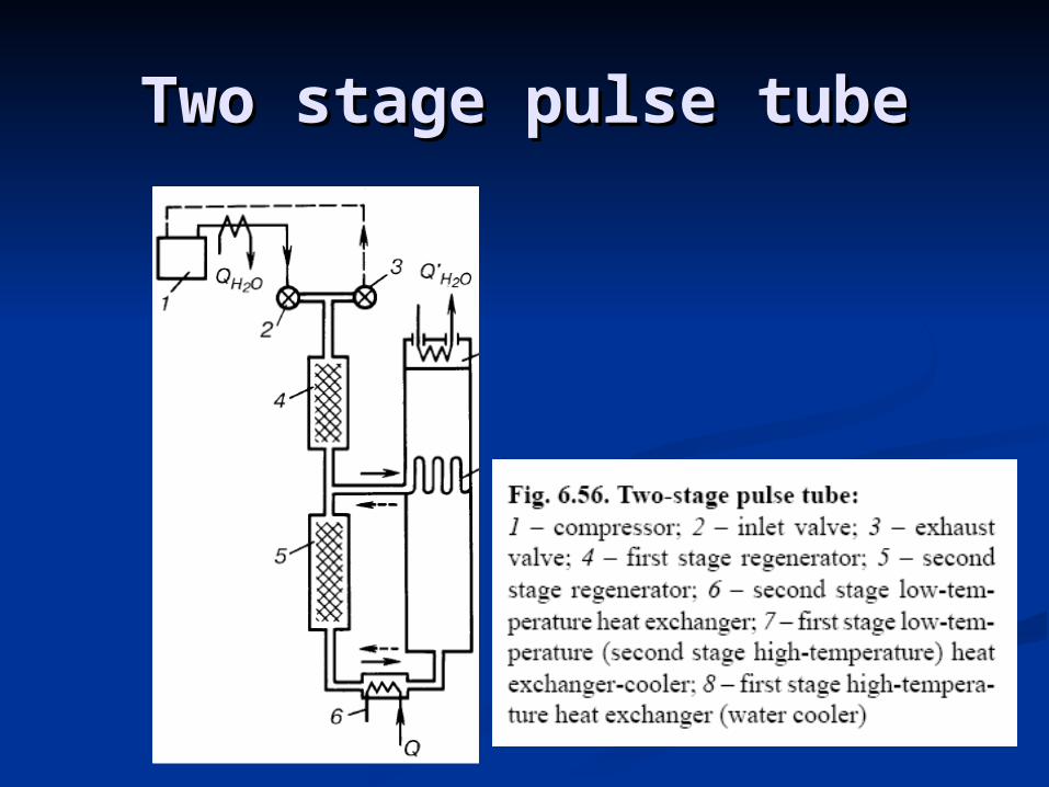
Two stage pulse tubeTwo stage pulse tube
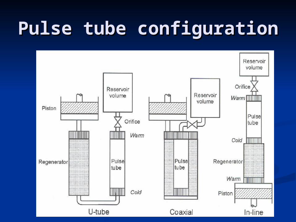
Pulse tube configurationPulse tube configuration

Adiabatic demagnetization Adiabatic demagnetization of paramagneticof paramagnetic

Paramagnetic saltsParamagnetic salts

Magnetic coolersMagnetic coolers

Magnetic coolerMagnetic cooler

Magnetic cooler with Magnetic cooler with moving paramagneticmoving paramagnetic

Three stage magnetic Three stage magnetic cooler with magnetic cooler with magnetic
regeneratorregenerator
Ceramic magnetic regenerator material Gd2O2S with an average diameter of 0.35 mm for G-M and pulse tube cryocoolers.

Cooler efficiency at 80 KCooler efficiency at 80 K

„„Family” of cryocoolersFamily” of cryocoolers