reduction of harmonics using active filter for power ... · power quality improvement abdul wadood,...
TRANSCRIPT

Reduction of Harmonics using Active Filter for
Power Quality Improvement Abdul Wadood, Chang Hwan Kim, Saied Gholami Farkoush, Tahir Khurshaid, Kumail Hassan Kharal, Sang-Bong
Rhee
Abstract - To transmit an accurate, reliable and flexible power
without any distortion to consumer is a serious issue and
challenging to industry especially for engineer. During
transmission, a lot of power problem occur which affect the
power system operation and efficiency. There are several issues
regarding power quality of which harmonics affect the power
system operation and their extenuation should be given
preeminent importance. Among different types of harmonic
filters, active power is examined as very much profitable and
economical solution. This paper presents the simulation of active
power filter for reduction of harmonics using mitigation
techniques MATLAB/Simulink software.
Keywords: Active power filter, PI controller, RL load power
quality, Total harmonic distortion (THD).
I. Introduction
In recent years power quality problem was seriously
addressed and considered by power engineers. Power quality
problem is not the name of a single problem occur in electric
power system there are various power quality problems which
exist in any transmission and distribution network like
reactive power balance, voltage sag, voltage swell, voltage
interruption, transients, and harmonics out of all these
problems harmonics is one of the major hurdle in power
system which creates a lot of interruptions. In this respect
community and industry deals with this problem i.e. PQ
(power quality), due to their awareness how to maintain the
standard of power grid, so industries try to train the new
generation to handle the power quality issues. Harmonics can
be defined as those components which are present in the
fundamental waveform or signal of voltage and current and
they are integer multiples of fundamental frequency
component. Harmonics creates an unwanted trouble in load
operation as well as reduces the efficiency and performance
of the equipment [1]. In power system nonlinear loads are the
main designer of harmonics that injects harmonic currents in
A.C system and results in an increase of reactive power
supplied by Equivalent Load [2]. This increase in nonlinear in
nonlinear electronic base load leads to harmonic pollution
Abdul Wadood, Chang Hwan Kim, Saied Gholami Farkoush, Tahir Khurshaid, Kumail Hassan Kharal Sang-Bong Rhee are with Department
of Electrical Engineering, Yeungnam University, Gyeongsan, 38549,
Republic of Korea. E-mails ([email protected], [email protected], [email protected], [email protected], [email protected], e-
mails of corresponding author:[email protected]
Paper submitted to the International Conference on Power Systems
Transients (IPST2017) in Seoul, Republic of Korea June 26-29, 2017
Which will affect the operation of power system and the
required result will not achieved successfully due to
Harmonics [3]. To eliminate the harmonics from the power
system there is the urge of harmonic filter to be utilized in
transmission network having the good configuration and the
parameters to control harmonics [4]. There are three main
types of harmonic filters namely passive, active and hybrid
harmonic filters [5]. Presently used filter were of passive type
which consist of inductor and capacitors. But later it was
inaugurated that active power filters have more advantages as
compared to passive harmonic filters [2] [6]. Thus the
occurrence of technology is the brick way for the
development of active power filter [7].
II. Objective and Principal of Operation
The objective of active power filter (APF) is to sort out that
issues in a prominent way rather than using those components
whose ratings are predetermined with reduced ratings unlike
bulky passive components [2]. Active power filter can be
implemented according to the nature of problem in power
system. APF filter have three basic topologies i.e. Shunt type,
series type and a combination of both shunt & series active
filters [8]. The basic topology of shunt active power filter
with a voltage source or a DC capacitor are similar to that of
STATCOM used for reactive power compensation in electric
power transmission network [9]. The concept and idea of APF
is slightly old but their practical achievement was made
possible with the new evolution in power electronics, control
strategies as well as with discount in worth of electronic
components [3]. Although the fast response of power
electronic switching, Active power filter originate current or
voltage components which remove the harmonic components
of the nonlinear loads. The shunt active filter reimburse load
current harmonics by inserting equal but opposite harmonic
current [4] [9]. In this manner, the operation of shunt power
filter is same like current source which inserts the harmonic
components initiated by the load giving a phase difference of
180 .The series active power filter performs like a voltage
regulator and also acts like a harmonic insulator between load
and the utility system [10]. In the SCF (series connected
filter) a coupling transformer is used to connect the filter to
the system. The compensation voltage, VC, is used to cancel
the load voltage harmonics caused due to nonlinear load like
diode rectifiers with capacitive load in the DC side that can
reduce imperfect supply voltage quality this type of
methodology is especially assign for voltage sag, interruption
and for unbalances in AC transmission system because at

fundamental frequency the filter is designed to offer a very
low impedance therefore allowing a fundamental current with
negligible voltage drop and losses In addition this filter must
be designed to carry fully rated load current with overcurrent
protection. Moreover at fundamental frequency these
consume lagging reactive power result in further voltage
drop. The figure 1 & 2 shown below illustrate the adjustment
of shunt active power filter in electrical network.
Figure 1. Active Power Filter Installation
Figure 2. APF schematic
During operation the compensation current obtained will be IC
(t) equal to error obtained from signal. If this properly output
is given to source side in phase opposition this lead to the
phase cancellation of harmonic components Although voltage
is the output of VSI and can be converted to current source
when RL is connected in series .Accordance with the
magnitude of compensating current the value of RL branch
can be determined. The steps involve in the process of active
harmonic filter are given below.
The extraction of harmonic components Inverter operates
compensating current control.
A. Harmonic Extraction Method
Various method are used for extraction of harmonic
component from fundamental component .Although it is done
in order to isolate the harmonic from supply signal or
waveform mathematically [11].some of the method used for
harmonic extraction [3] [8] are given below
Synchronous reference frame method, synchronous detection
method, Modified power quality theory, Sine multiplication
method.
B. Voltage Source Inverter (VSI)
The voltage source inverter is very reliable in operation and
can operate in all four quadrants that is supply and absorb
real as well as reactive power. Most of the topologies
nowadays used in active power filter use a voltage source
inverter for their operation. In VSI the phenomenon of self-
commutation is possible due to IGBTs and MOSFETs. The
advantages of voltage source converter are given below:
1. Fast control of both power i.e. Active & reactive
Power, Provide a good and high level of Power.
2. Low power (<250MW)
3. STATCOM and SVC
4. Active power filter and VAR computation [9]
Self-commutating switches which can be controlled
according to our desire (e.g. GTOs, IGBTs). In comparison
to the conventional CSCs which are operate with line
commuted thermistors switches [9]. The phenomena of
commutation in a force commutated voltage source
converter can occur many times regarding per cycle as in a
line commuted Current source converter it happen only once
per cycle. This quality allows the voltage and current to
generate a nearly sinusoidal output and able to control the
power factor as well. So VSI is an accessible choice for the
implementation of active filters [9].
Load
Edc Cdc
Q1
Q2
D1
D2
Q3
Q4
D3
D4
AB
++
-
Figure 3. Single phase VSI Topology
The topology shown in the figure shows the conversion of DC
voltage into an AC voltage by properly gathering the power
semiconductor switches. Voltage source converters are
preferred over current source converters due to its high
efficiency and lower initial cost as compared to current source
converters.
C. Pulse generation for Active Power Filter
The most important process in the operation of active power
filters for gathering of pulse generation there are various
techniques listed below.
1. Sine PWM
2. Space vector PWM
3. Triangular PWM [7].
Triangular pulse width modulation is the most commonly
technique applied to a voltage source inverter consist of
chopping the DC bus voltage to generate an AC voltage of an
arbitrary waveform. There are various PWM techniques
available to integrate the sinusoidal pattern, the phenomenon

over which this technique work is known as triangular carrier
technique .In this technique the output voltage is forced over
a switching cycle determined by the carrier period to be equal
to the average amplitude of the modulating wave known as
Vref .As for APF implementation is concerned this
methodology compares the output current error with a fixed
amplitude and triangular wave carrier. Thus the compensating
current produced for a shunt active power filter. The
schematic representation of PWM technique is given in figure
4.
Figure 4. Triangular PWM Technique
III. Proposed Modelling of active power System
The basic shunt power filter have the advantages of giving
advanced and effective result. A diode rectifier with
smoothing DC capacitor acts as a nonlinear load which
creates significant current distortion current. The current
harmonic amplitude is significantly affected due to Ac side or
source impedance .Passive filter have been extensively used
in power system to mitigate these harmonic distortions chiefly
due to their low cost. In the given paper current harmonics
caused due to non-linear load having an RL load has been
taken for Analysis as a test system. Shunt active power filter
is used to inject the compensating currents in order to have
purely sinusoidal source current at unity power factor.it
consist of a voltage source inverter having a voltage source at
the DC bus, which typically is an energy storage device like a
capacitor as shown in figure 5.
Q3
AC
RCC
C1
LCC
AC
AC
Lr
R
L
LS
Q2Q1
Q6Q5Q4
DC
Ic1 IL1
Ic2 IL2
Ic3 IL3
D1 D2 D3
D4 D5 D5
PCC
PCC
PCC
Figure 5 single line diagram of shunt active power filter
Figure 5 show the basic compensation principal of a shunt
active power filter in which the compensation current Ic
cancels the current harmonics on AC side. From figure1 the
instantaneous source currents can be written as
)()()( t
CIt
LIt
SI (1)
Source voltage is given by )sin()( tVtV mS (2)
For a nonlinear load the load current will have a fundamental
component and the harmonic component, which can be
further given by.
)sin()sin()sin()(
21
11 n
n
n
n
nnL tnItnItnItI
(3)
Instantaneous load power can be given as
)sin(sin
sin*cos*sincos*sin)(*)()(
2
1112
1
n
n
nm
mmLSL
tnItV
ttIVtIVtItVtP
(4)
)()()( tPtptp hrf (5)
From (4), real (fundamental) power drawn by the load
)(*)(cos*sin)( 12
1 tItVtIVtp ssmr (6)
Form (6) source current supplied by the source after
compensation
11 cos*sin)(/)()( tItVtptI srs (7)
Where
11 cosIIsm (8)
Hence total peak current supplied by the source
SLsmsp III (9)
Where ISL represents the PWM converter switching loss. In
case active power filter provides the total reactive and
harmonic power, then Is (t) will be in phase with the service
voltage and will be entirely sinusoidal.at this stage of time
compensation current is: )()()( t
SIt
LIt
CI (10)
Thus it is important to compute Is (t) for precise and
instantaneous compensation of reactive and harmonic
power.
IV. Recommended Approach & Strategy
Vdc
Vdc ref
e
I*PPI
Controller
Reference
Current
generator
Iabc
Hysterious
Current
Controller
PI
Controller
Figure 6. Block diagram of shunt active power filter
The control block diagram of SAPF consist of a Three phase
shunt active power filter have a voltage source inverter
(VSI) having IGBT switches and an energy storage capacitor
on DC bus. The control block consists of the PI controller
and the Hysteresis current controller (HCC). The work of PI
controller is the evaluation of reference current from the
measured DC bus voltage. The job of HCC is to generate the
switching pulses for the VSI. HCC comprises of the
following components.
D. Unit vector Template Formation
The input source voltage at point of common coupling (PCC)
consists of fundamental and distorted component. In order to
get unit vector templates of voltage, the input voltage is
sensed and multiplied by gain which is equal to 1/VM, where
VM represents the peak amplitude of fundamental input
voltage. These unit vector templates are then given to a
multiplication block for synchronization of signals. The unit
vector templates for three phases are obtained as follows. tvsa sin (11)
)120(sin tvsa (12)
)120(sin tvsa (13)
E. Reference Source Current
The peak value of the reference current ISP can be
determined by controlling the DC side capacitor voltage. The
best compensation requires the mains current to be sinusoidal
and in phase with the source voltage irrespective nature of
load current. The desired source current after compensation is
given by:
tII spsa sin*
(14)
)120(sin* tII spsb (15)
)120(sin* tII spsc (16)
Here sLsp III )(cos 11 is the amplitude of the desired source
current, while the phase angles can be obtained from the
source voltage. Thus, the waveform and phases of the source
currents are known, just the magnitude of the source currents
needs to be determined. Peak value of the reference current
has been obtained by regulating the dc side capacitor voltage
of PWM converter. This capacitor voltage is compared with
the reference value and the error is processed in a PI
controller. The output of PI controller is the amplitude of the
desired source current and the reference currents are
estimated by multiplying this peak value with the unit sine
vector templates in phase with the source voltages.
F. Control strategy used in HCC
Hysteresis Current Control (HCC) technique is basically an
instantaneous feedback current control method of pulse
width modulation (PWM) where the actual current
continually tracks the command current within a hysteresis
band. The actual source currents Isa, Isb and Isc are compared
in hysteresis current controller in order to generate the
control pulses for switches of VSI in such a way so that the
actual source current follows the reference currents closely
inside the narrow hysteresis band. This makes source
currents almost sinusoidal and in phase with source voltages,
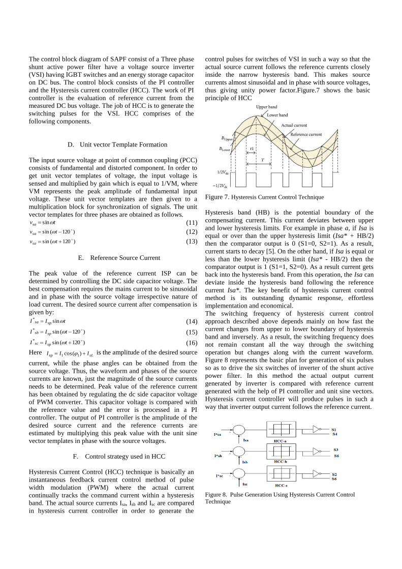
thus giving unity power factor.Figure.7 shows the basic
principle of HCC
Figure 7. Hysteresis Current Control Technique
Hysteresis band (HB) is the potential boundary of the
compensating current. This current deviates between upper
and lower hysteresis limits. For example in phase a, if Isa is
equal or over than the upper hysteresis limit (Isa* + HB/2)
then the comparator output is 0 (S1=0, S2=1). As a result,
current starts to decay [5]. On the other hand, if Isa is equal or
less than the lower hysteresis limit (Isa* - HB/2) then the
comparator output is 1 (S1=1, S2=0). As a result current gets
back into the hysteresis band. From this operation, the Isa can
deviate inside the hysteresis band following the reference
current Isa*. The key benefit of hysteresis current control
method is its outstanding dynamic response, effortless
implementation and economical.
The switching frequency of hysteresis current control
approach described above depends mainly on how fast the
current changes from upper to lower boundary of hysteresis
band and inversely. As a result, the switching frequency does
not remain constant all the way through the switching
operation but changes along with the current waveform.
Figure 8 represents the basic plan for generation of six pulses
so as to drive the six switches of inverter of the shunt active
power filter. In this method the actual output current
generated by inverter is compared with reference current
generated with the help of PI controller and unit sine vectors.
Hysteresis current controller will produce pulses in such a
way that inverter output current follows the reference current.
Figure 8. Pulse Generation Using Hysteresis Current Control
Technique

V. PI controller
The work of PI controller is the evaluation of reference
current from the measured DC bus voltage. Proportional
Integral (PI) controller has been extensively used for DC bus
voltage regulation in shunt active power filters. It is effortless
to implement and achieves excellent results. The control
scheme of a shunt active power filter should calculate the
reference current waveform for each of the three phase of the
inverter, maintain the dc link voltage constant, and generate
the inverter gating pulses. PI controller consists of a
proportional term i.e. KP and an integral term i.e. Ki.
Proportional value is used determines the response to the
current error; similarly the Integral part is used to determine
the response based on the sum of recent errors. The transfer
function of the PI controller is given by sKKsH Ip /)( (17)
Here the proportional and integral gains are selected either
heuristically or mathematically. The integral term causes the
steady-state error to trim down to zero; however it is not the
case for proportional-only control. PI controllers are
commonly used than Proportional Integral Derivative (PID)
controllers because the derivative action is very sensitive to
noise, in this manner making PI system steadier in the Steady
state in the case of a noisy environment.
VI. Simulation and Results
The proposed system is simulated using MATLAB/Simulink
and Sim Power Systems software to validate the performance
of proposed method. The system parameters are presented in
Table-I.
Serial No. Parameter value
1. Source voltage 230V(r.m.s)
2. Source
frequency 50Hz
3. DC bus voltage 600V
4. DC bus
capacitor
3.5μF
5. DC link
inductance
10mH
6. Hysteresis Band ± 5
7. Load resistance 60Ω
8. Load inductance 10mH
9. Sample time 0.2µseconds
Table-I: System Parameters
The system is first simulated without filter in order to the
system is first simulated without filter in order to investigate
the effect of non- linear loads in power systems. Figure 9
shows the three phase source current drawn by non-linear
load in absence of active power filter. The result shows that
the current drawn is not sinusoidal and is not in phase with
the source voltage.
Figure 9. Source current without Shunt Active Power Filter
G. FFT Analysis
When filter is not used THD is also high due to nonlinear load.
Figure 10 shows THD due to nonlinear load in absence of
filter. The source current is highly distorted with a THD of
28.38% as shown in Figure 10. The source current THD is
much greater than the acceptable limit of 5% set by IEEE-
519-1992 standard.
0 0.02 0.04 0.06 0.08 0.1 0.12 0.14 0.16 0.18 0.2
Time (s)
-0.5
0
0.5
1
Sig
nal m
ag
Selected signal: 10 cycles. FFT window (in red): 3 cycles
0 2 4 6 8 10 12 14 16 18 20
Harmonic order
0
5
10
15
20
Fundamental (50Hz) = 0.9568 , THD= 28.38%
Ma
g (
% o
f F
un
da
me
nta
l)
Figure 10. THD due to nonlinear load without filter
Now a shunt active power filter is used for harmonics and
reactive power compensation. The result shows that the
current drawn is sinusoidal and is in phase with the source
voltage Figure 11 shows the source current has become near
sinusoidal after using shunt active power filter thus improving
the power factor and reducing THD from 28.38 to 2.08 as

shown in figure 12 and Table-II
Figure 11. source current with shunt active filter
0 0.02 0.04 0.06 0.08 0.1 0.12 0.14 0.16 0.18 0.2
Time (s)
-1
-0.5
0
0.5
1
Selected signal: 3 of 10 cycles of selected signal. FFT window (in red): 3 cycles
Sig
na
l m
ag
0 2 4 6 8 10 12 14 16 18 20
Harmonic order
0
0.1
0.2
0.3
0.4
0.5
0.6
0.7
0.8
0.9
Fundamental (50Hz) = 1.048 , THD= 2.08%
Mag
(%
of
Fu
nd
am
en
tal)
Figure 12. THD due to nonlinear load with filter
Table 2 shows the comparative analysis of Shunt active
power Filter to reduce the THD
Filter THD
Without shunt active
power filter
28.38
With shunt active power
filter
2.08
Table-II THD With and without shunt active power filter
VII. Conclusion
This chapter intents at studying the Performance of shunt
hybrid active power filter to the three phase system and the
concussion and role of shunt active power filters in mitigation
of Harmonics. The concept of shunt hybrid active power
filters requires different harmonic extraction and different control methods which can be surveyed to suggest a better
solution. A shunt active filter has the quality of dynamism,
robustness and doesn't cause electrical resonance or isn't made
up of large or bulky equipment’s. Hybrid filters topologies
help in damping resonances occurring between line
impedances and passive filters and provide cost-effective,
superior efficiency, improved reliability and better solutions
for harmonic compensation with an extremely small-rated
inverter as compared to active. Power filter topologies and
other options of power quality improvement. Thus it could be
an economical solution to deal with current harmonics issues.
Moreover, this design requires compact size of shunt active
power filter
VIII. References
[1] Akagi, H. “New trends in active filters for Power
conditioning”, IEEE Transactions on Industrial
Applications Volume. 32(6): 1312-1322, 1996
[2] Akagi. H, “Modern active filters and Traditional passive
filters”, Bulletin of the Polish Academy of Sciences,
Technical Sciences 54(3), 255-269, 2006. [3] K-L. Areerak and K-N. Areerak, “The Comparison Study
of Harmonic Detection Methods for Shunt Active Power
Filters”, World Academy of Science, Engineering and Technology 46 2010 pg. 243-248
[4] Bhim Singh, Kamal AI-Haddad & Ambrish Chandra,
“A Review of Active Filters for Power Quality
Improvement”, IEEE Transactions on Industrial
Electronics, Volume. 46, No. 5, pp 960-970, Oct. 1999.
[5] S.Khalid & Bharti Dwivedi “Power Quality Issues,
Problems, standards & their effects in industry with
corrective means”, International Journal of Advances In Engineering & Technology, May 2011.
[6] L. Moran, J. Dixon, J. Espinoza, & R.Wallace, “Using
Active Power Filters to Improve Power Quality”, 5th
Brasilian Power Electronics Conference, COBEP'99.
[7] Muhammad H. Rashid, “Power electronics -circuits,
devices and APPLICATIONSTHIRD EDITION”, Pearson, New Jersey, USA.
[8] Vedat M. Karsh, Mehmet Tumay, Berrin SOslOoglu,
“An evaluation of time domain techniques for compensating currents of SHUNT ACTIVE POWER FILTERS”.
[9] Vijay K Sood, "HVDC and FACTS controllers-
Applications of Static Converters in power systems
Kluwer Academic Publishers, 2004.
[10] Zainal Salam, Tan Perng Cheng and Awang Jusoh,
“Harmonics Mitigation Using Active Power Filter: A
Technological Review” ELEKTRIKA.
[11] Anzari M, Rejil Chandran and ArunKumar R, “Single-
Phase Shunt Active Power Filter Using Indirect Control
Method” Advance in Electronic and Electric Engineering ISSN 2231-1297, Volume 3, Number 1
(2013), pp. 81-90