reduction of fluid forces on a square cylinder ina … of fluid forces on a square cylinder ina...
TRANSCRIPT

Reduction of Fluid Forces on a Square Cylinder in a Laminar Flow using Passive Control Methods Aisha S. Abograis, and Adel E. Alshayji* Department of Mechanical Engineering, College of Engineering and Petroleum, Kuwait University. *Corresponding author: P.O. Box 5969, Safat, 13060, Kuwait. [email protected] Abstract: COMSOL is used in this study to simulate the flow around a square cylinder and focus on reducing the forces on the cylinder by passive control methods. Numerical simulations are made to find optimum cases of control methods that guarantee maximum reduction for Reynolds number 160 based on the width of the square cylinder (W) and the inlet flow velocity (𝑈!"). The optimum cases would be found by placing a vertical upstream control plate 3W away from the square cylinder with a height of 0.5W and a horizontal downstream control plate of width W either ranging from the rear of the square cylinder to 0.3W or 0.5W to 1.3W. The selection of the optimum cases is made based on flow patterns, lift coefficient of cylinder, drag coefficient of cylinder and plates, rms drag coefficient of cylinder, rms lift coefficient of cylinder, and Strouhal’s number. The effect of changing Reynolds number from 50 to 200 is also studied on these parameters. Keywords: Reduction of fluid forces, Passive control methods, square cylinder, laminar flow, and vortex shedding. 1. Introduction
Engineering design is concerned with the flow around cylinders. In real life, the flow around cylinders resembles flow around buildings, chimneys, bridges, and heat exchanger pipes. Uncontrolled flow can cause unsteady wake (vortex shedding) behind the body, which will lead to high fluid forces and flow-induced vibrations. Flow control methods can reduce the unsteadiness, forces, wake, and separation of the flow. Effective flow control can save energy, increase propulsion efficiency, and reduce induced vibration of the body.
Fluid mechanics is the study of forces that act on an object moving through a fluid. Three main fluid forces are buoyancy, drag, and lift. The drag force acts in the opposite direction of the relative flow velocity. The lift force acts in
the perpendicular direction of the relative flow velocity. These two forces are made up of two components: pressure and friction, which are the main concern of this study. The goal is finding the cases of minimum forces acting on the body.
Malekzadeh and Sohankar [1] classified flow control mechanisms as active and passive control methods. Active control methods control the flow by using external energy. An example of this method is a jet blower. Passive control methods control the flow by modifying the shape of the body or attaching additional devices. Examples of passive control methods are control plates and roughness elements. Compared to active control methods, passive control methods are simpler, easier, and less costly.
Many researchers studied different passive control methods to reduce the fluid forces on the body in the flow. Ali et al [2] studied downstream flat control plate, Baek and Karniadakis [3] simulated slit and shell on the body in the flow, Bao et al [4] worked with inline array of bodies in the flow, Bao and Tao [5] focused on attaching parallel dual plates behind body in flow, Bruneau and Mortazavi [6] concentrated on covering the body in flow by porous media, Malekzadeh and Sohankar [1] and Zhou et al [7] studied using an upstream control plate.
In this study, the model used is validated with the results in the paper of Malekzadeh and Sohankar [1]. The aim of this study is to improve the validated results with additional passive control methods by means of more reduction of fluid forces on the square cylinder. For the validation a vertical control plate is placed upstream of the square cylinder with a varying height (0.1-0.9W) and varying distance (1.1-7W). The results are improved by adding a horizontal downstream control plate of width of W and varying distance (0-2W).
This paper is organized to state the problem under study with its computational domain, governing equations, boundary conditions, and mesh. Followed by validating the simulation
Excerpt from the Proceedings of the 2013 COMSOL Conference in Boston

results with the published paper and suggesting other methods by focusing on the drag, and lift coefficients. Finally, drawing some conclusions about the results reached.
2. Use of COMSOL Multiphysics This study is about a flow over a square cylinder in tandem arrangement with control plates upstream and downstream. As shown in Figure 1, the computational domain is with width of 20W, inlet distance (from inlet to vertical upstream control plate) of 10W, and outlet distance (from rear of the square cylinder to outlet) of 15W. The computational domain is based on the work of Malekzadeh and Sohankar [1]. The unity parameters are the inlet velocity (𝑈!"), the width of the square cylinder (W), and the density of the flow (𝜌). The control plates’ thicknesses are P=0.005W. In their work, the vertical upstream control plate has a variable height (h) and a variable distance between the plate and the cylinder (S) changes from 0.1W to 0.9W and 1.1W to 7W, respectively. The horizontal downstream control plate has a fixed width (W) and variable distance between the plate and the rear of the square cylinder (X) changes from 0 (attached) to 2W.
Since the fluid forces are fluctuating, the problem is unsteady. The governing equations can be reduced for the case of unsteady two-dimensional laminar incompressible flow. The model used in COMSOL is with 2D space dimension, Laminar Flow (spf) physics, and time dependent study. The governing equations used in this study are the continuity equation, momentum equation in the x direction, and momentum equation in the y direction. The dimensionless governing equations are:
The continuity equation: 𝜕𝑈𝜕𝑋 +
𝜕𝑉𝜕𝑌 = 0 (1)
The momentum equation in the x direction: 𝜕𝑈𝜕𝜏 +
𝜕(𝑈𝑈)𝜕𝑋 +
𝜕(𝑉𝑈)𝜕𝑌 = −
𝜕𝑃𝜕𝑋 +
1𝑅𝑒
𝜕!𝑈𝜕𝑋! +
𝜕!𝑈𝜕𝑌! (2)
The momentum equation in the y direction: 𝜕𝑉𝜕𝜏 +
𝜕(𝑈𝑉)𝜕𝑋 +
𝜕(𝑉𝑉)𝜕𝑌 = −
𝜕𝑃𝜕𝑌 +
1𝑅𝑒
𝜕!𝑉𝜕𝑋! +
𝜕!𝑉𝜕𝑌! (3)
The dimensionless equation are scaled by the relations:
𝑈 =𝑢𝑈!"
,𝑉 =𝑣𝑈!"
, 𝜏 =𝑡𝑈!"𝑊 ,
𝑋 =𝑥𝑊 ,𝑌 =
𝑦𝑊 ,𝑃 =
𝑝𝜌𝑈!"!
(4)
where 𝑥 and 𝑦 are the dimension coordinates directions along and perpendicular to the stream, respectively. 𝑢 and 𝑣 are the velocities along and perpendicular to the stream, respectively. 𝑝 is the pressure and 𝑡 is the time. The dimensionless number used in this study is Reynolds number 𝑅𝑒 = !!"!
! where 𝜈 is the kinematic viscosity.
The boundary conditions used in the simulation of the model are:
• Slip top and bottom boundaries resemble far field condition.
• No-slip boundary conditions on the square cylinder and control plates’ sides.
• Normal inflow velocity at the inlet: 𝑢 = 𝑈!", 𝑎𝑛𝑑 𝑣 = 0.
• Pressure, no viscous stress at the outlet. The time marching calculations of the simulation model is made with constant time step ∆𝑡 = 0.025 seconds based on the work of Malekzadeh and Sohankar [1]. The mesh of the model is of sequence type physics-controlled mesh with an element size of extremely fine. This mesh is adjustable for each run automatically. The mesh of the model is shown in Figure 2 and Figure 3.
Figure 1. Computational domain for fluid around a square cylinder and a control plate.
Figure 2. Computational domain with extremely fine mesh for upstream and downstream control plate case.
S10W 15Wh
P
W20W
XP
Upstream control plate
Downstream control plateCylinder
UinW
Excerpt from the Proceedings of the 2013 COMSOL Conference in Boston
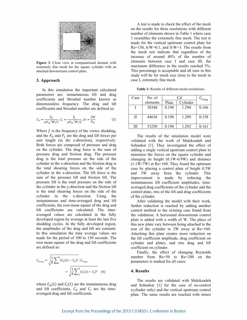
Figure 3. Close view at computational domain with extremely fine mesh for the square cylinder with an attached downstream control plate. 3. Approach In this simulation the important calculated parameters are: instantaneous lift and drag coefficients and Strouhal number known as dimensionless frequency. The drag and lift coefficients and Strouhal number are defined as: 𝐶! =
𝐹!𝜌𝑈!"!𝑊/2
,𝐶! =𝐹!
𝜌𝑈!"!𝑊/2, 𝑆𝑡 =
𝑓𝑊𝑈!"
(5)
Where 𝑓 is the frequency of the vortex shedding, and the 𝐹! and 𝐹! are the drag and lift forces per unit length (in the z-direction), respectively. Both forces are composed of pressure and drag on the cylinder. The drag force is the sum of pressure drag and friction drag. The pressure drag is the total pressure on the side of the cylinder in the x-direction and the friction drag is the total shearing forces on the side of the cylinder in the x-direction. The lift force is the sum of the pressure lift and friction lift. The pressure lift is the total pressure on the side of the cylinder in the y-direction and the friction lift is the total shearing forces on the side of the cylinder in the x-direction. Using the instantaneous and time-averaged drag and lift coefficients, the root mean square of the drag and lift coefficients are calculated. The time-averaged values are calculated in the fully developed region by average at least the last five shedding cycles. In the fully developed region, the amplitudes of the drag and lift are constant. In this simulation the time average values are made for the period of 100 to 150 seconds. The root mean square of the drag and lift coefficients are defined as:
𝐶!!"# =1𝑁 𝐶!(𝑡) − 𝐶! !
!
!,𝐶!!"#
=1𝑁 𝐶!(𝑡) − 𝐶! !
!
! (6)
where 𝐶!(𝑡) and 𝐶!(𝑡) are the instantaneous drag and lift coefficients, 𝐶! and 𝐶! are the time-averaged drag and lift coefficients.
A test is made to check the effect of the mesh on the results for three resolutions with different number of elements shown in Table 1 where case 1 resembles the extremely fine mesh. The test is made for the vertical upstream control plate for Re=150, h/W=0.1, and S/W=3. The results from the mesh test indicate that regardless of the increase of around 40% of the number of elements between case I and case III, the maximum difference in the results reached 3%. This percentage is acceptable and all runs in this study will be for mesh size close to the mesh in case I, extremely fine mesh.
Table 1: Results of different mesh-resolutions.
Case No. of elements
Cd 𝐶!!"# Plate Cylinder
I 38340 0.198
1.294
0.166
II 44636 0.198
1.289
0.158
III 53250 0.198 1.292 0.161
The results of the simulation model were validated with the work of Malekzadeh and Sohankar [1]. They investigated the effect of adding a single vertical upstream control plate to minimize the forces on the square cylinder and changing its height (0.1W-0.9W) and distance (1.1W-7W) at Re=160. They found the optimum case by placing a control plate of height 0.5W and 3W away from the cylinder. This improvement is made by reducing the instantaneous lift coefficient amplitudes, time-averaged drag coefficients of the cylinder and the control plate, rms of the lift and drag coefficients of the cylinder. After validating the model with their work, farther reduction is reached by adding another control method to the existing case found from the validation. A horizontal downstream control plate is added with a width of W. The place of this new plate vary between being attached to the rear of the cylinder to 2W away at Re=160. Attaching this plate creates more reduction on the lift coefficient amplitude, drag coefficient on cylinder and plates, and rms drag and lift coefficient on cylinder. Finally, the effect of changing Reynolds number from Re=50 to Re=200 on the parameters is studied for all cases. 4. Results The results are validated with Malekzadeh and Sohankar [1] for the case of no-control (cylinder only) and the vertical upstream control plate. The same results are reached with minor
Excerpt from the Proceedings of the 2013 COMSOL Conference in Boston

differences because of using different meshes in the simulation. The best case for the vertical upstream control plate that improves the no-control case is found to be when h/W=0.5 and S/W=3 for Reynolds number 160. Comparing Figure 4 and Figure 5, the amplitude of the lift coefficient decreased by 86%. Trying to improve the results of Malekzadeh and Sohankar [1] furthermore, an additional control method is used by having the combination of vertical upstream and horizontal downstream control plates. The vertical upstream is kept in the best location (h/W=0.5 and S/W=3) and the horizontal downstream plate is attached to the rear of the cylinder. When comparing this new case in Figure 6 with the no-control case in Figure 4, the amplitude of the lift coefficient is decreased by 95%. Trying to improve the no-control case with only a downstream horizontal attached control plate in Figure 7 is proven to be not as useful as the previous two cases. The reduction in the lift coefficient amplitude reached 23% compared to the no-control case. For Reynolds number 160, the cases are tested to find the optimum cases that ensures maximum reduction in the amplitude of the instantaneous lift coefficients, time-averaged drag coefficients on cylinder and cylinder with plates, rms of the lift and drag coefficients for this study. From Figure 8, minimum lift coefficient amplitude is found when the combined control method is used that consists of the vertical upstream and horizontal downstream control plates. When X/W is greater than 1.8, the use of a vertical upstream control plate has less lift amplitude coefficient. From Figure 9, the combination control method decreases Strouhal number for X/W greater than 0.9, which leads to decreasing vortex shedding velocity behind the cylinder. The use of only downstream control plate also decreases Strouhal number after X/W=1.2. Figure 10 shows that the combination control method is the best option to reduce the time-averaged drag coefficient on the cylinder for all ranges of X/W. The rms of the drag coefficient on the cylinder in Figure 11 is minimum for the combination control method of X/W between 0 to 0.3 and 0.6 to 1.4. For the range of X/W between 0.3 to 0.6 the use of vertical upstream control plate only guarantees more reduction and the range between 1.4 to 2 the use of downstream control plate only decreases the value the most. The rms of the lift coefficient in Figure 12 is minimum for the combination control method of all ranges of X/W except greater than 1.8. The vertical upstream control plate only becomes a better option if X/W is greater than 1.8. Figure 13 through Figure 16 shows the variation of Strouhal number, time-average drag
coefficient, rms of the lift and drag coefficients on cylinder versus Reynolds number. These results are validated with available literature data for the cases of no-control and vertical upstream control plate from Malekzadeh and Sohankar [1] and Sharma et al. [7]. The results are in good agreement with the literature with some differences caused by using different meshes. As Reynolds number increases Strouhal number increases for the case with upstream control plate as shown in Figure 13. Using an upstream control plate decreases Strouhal number compared to the no-control case when Reynolds number is between 50 to 140. Using an upstream and downstream control plates together decreases Strouhal number compared to the no-control case when Reynolds number is between 50 to 60 and 130 to 150. Figure 14 shows that the time-averaged drag coefficient on the cylinder decreases as Reynolds number increases for all cases. Figure 15 and Figure 16 shows the rms of the lift and drag coefficient on the cylinder versus Reynolds number. As Reynolds number increases, the rms lift and drag coefficients increase for the no-control case. However with the vertical control plate rms lift coefficient increases in the range of Reynolds 50 to 100, decreases for Reynolds number 100 to 150, and becomes almost steady for Reynolds number 150 to 200. For the combination o the upstream and downstream control plates case, the rms of the drag coefficient stays constant as Reynolds number increases. The rms of the drag coefficient for the vertical upstream control plate and the combination of the upstream and downstream control plates case becomes almost steady as Reynolds number increases.
Figure 4. Instantaneous lift coefficient and power spectrum diagrams for no-control case at Re=160.
100 110 120 130 140 150−0.4
−0.3
−0.2
−0.1
0
0.1
0.2
0.3
0.4
t
Cl
0 0.2 0.4 0.6 0.8 10
50
100
150
Freq. (Hz)
FFT
AMP.
Excerpt from the Proceedings of the 2013 COMSOL Conference in Boston

Figure 5. Instantaneous lift coefficient and power spectrum diagrams for upstream control plate placed h/W=0.5 and S/W=3 case at Re=160.
Figure 6. Instantaneous lift coefficient and power spectrum diagrams for upstream control plate placed h/W=0.5 and S/W=3 and downstream control plate attached to the rear of the cylinder (X/W=0) case at Re=160.
Figure 7. Instantaneous lift coefficient and power spectrum diagrams for downstream control plate attached to the rear of the cylinder (X/W=0) case at Re=160.
Figure 8. Amplitude of the instantaneous lift coefficient for different X/W at Re=160 for the cases of: no-control, vertical upstream control plate (h/W=0.5 and S/W=3), vertical upstream (h/W=0.5 and S/W=3) and horizontal downstream control plates, and horizontal downstream control plate.
Figure 9. Strouhal number for different X/W at Re=160 for the cases of: no-control, vertical upstream control plate (h/W=0.5 and S/W=3), vertical upstream (h/W=0.5 and S/W=3) and horizontal downstream control plates, and horizontal downstream control plate.
Figure 10. Time-averaged drag coefficient of the square cylinder for different X/W at Re=160 for the cases of: no-control, vertical upstream control plate (h/W=0.5 and S/W=3), vertical upstream (h/W=0.5 and S/W=3) and horizontal downstream control plates, and horizontal downstream control plate.
100 110 120 130 140 150−0.05
−0.04
−0.03
−0.02
−0.01
0
0.01
0.02
0.03
0.04
0.05
t
Cl
0 0.2 0.4 0.6 0.8 10
1
2
3
4
5
6
7
8
9
10
Freq. (Hz)FF
T AM
P.
100 110 120 130 140 150−0.02
−0.015
−0.01
−0.005
0
0.005
0.01
0.015
0.02
t
Cl
0 0.2 0.4 0.6 0.8 10
0.2
0.4
0.6
0.8
1
1.2
1.4
1.6
1.8
2
Freq. (Hz)
FFT
AMP.
100 110 120 130 140 150
−0.25
−0.2
−0.15
−0.1
−0.05
0
0.05
0.1
0.15
0.2
0.25
t
Cl
0 0.2 0.4 0.6 0.8 10
0.2
0.4
0.6
0.8
1
1.2
1.4
1.6
1.8
2
Freq. (Hz)
FFT
AMP.
0 0.2 0.4 0.6 0.8 1 1.2 1.4 1.6 1.8 20
0.05
0.1
0.15
0.2
0.25
0.3
0.35
0.4
X/W
Clm
ax
No−controlUpstreamUpstream−downstreamDownstream
0 0.2 0.4 0.6 0.8 1 1.2 1.4 1.6 1.8 20.1
0.11
0.12
0.13
0.14
0.15
0.16
0.17
0.18
0.19
0.2
X/W
St
No−controlUpstreamUpstream−downstreamDownstream
0 0.2 0.4 0.6 0.8 1 1.2 1.4 1.6 1.8 20
0.5
1
1.5
2
X/W
Cd
No−controlUpstreamUpstream−downstreamDownstream
Excerpt from the Proceedings of the 2013 COMSOL Conference in Boston

Figure 11. The rms drag coefficient of the square cylinder for different X/W at Re=160 for the cases of: no-control, vertical upstream control plate (h/W=0.5 and S/W=3), vertical upstream (h/W=0.5 and S/W=3) and horizontal downstream control plates, and horizontal downstream control plate.
Figure 12. The rms lift coefficient of the square cylinder for different X/W at Re=160 for the cases of: no-control, vertical upstream control plate (h/W=0.5 and S/W=3), vertical upstream (h/W=0.5 and S/W=3) and horizontal downstream control plates, and horizontal downstream control plate.
Figure 13. Strouhal number versus Reynolds number for the cases of: no-control, vertical upstream control plate (h/W=0.5 and S/W=3), and vertical upstream (h/W=0.5 and S/W=3) and horizontal downstream control plates (attached X/W=0).
Figure 14. Time-averaged drag coefficient of the square cylinder versus Reynolds number for the cases of: no-control, vertical upstream control plate (h/W=0.5 and S/W=3), and vertical upstream (h/W=0.5 and S/W=3) and horizontal downstream control plates (attached X/W=0).
Figure 15. The rms drag coefficient of the square cylinder versus Reynolds number for the cases of: no-control, vertical upstream control plate (h/W=0.5 and S/W=3), and vertical upstream (h/W=0.5 and S/W=3) and horizontal downstream control plates (attached X/W=0).
Figure 16. The rms lift coefficient of the square cylinder versus Reynolds number for the cases of: no-control, vertical upstream control plate (h/W=0.5 and S/W=3), and vertical upstream (h/W=0.5 and S/W=3) and horizontal downstream control plates (attached X/W=0).
0 0.2 0.4 0.6 0.8 1 1.2 1.4 1.6 1.8 2−0.005
0
0.005
0.01
0.015
0.02
0.025
X/W
Cdr
ms
No−controlUpstreamUpstream−downstreamDownstream
0 0.2 0.4 0.6 0.8 1 1.2 1.4 1.6 1.8 2−0.1
−0.05
0
0.05
0.1
0.15
0.2
0.25
0.3
0.35
0.4
X/W
Clrm
s
No−controlUpstreamUpstream−downstreamDownstream
0 50 100 150 200 2500.08
0.1
0.12
0.14
0.16
0.18
0.2
0.22
0.24
Re
St
Present work − without control plateMalekzadeh and Sohankar 2012 − without control plateMalekzadeh and Sohankar 2012 − with control platePresent work − upstream control platePresent − upstream and downstream control plates
0 50 100 150 200 2500
0.5
1
1.5
2
2.5
Re
Cd
Present work − without control plateMalekzadeh and Sohankar 2012 − without control plateSharma et al 2004 − without control plateMalekzadeh and Sohankar 2012 − upstream control platePresent work − upstream control platePresent work − upstream and downstream control plates
0 50 100 150 200 250−0.005
0
0.005
0.01
0.015
0.02
0.025
0.03
0.035
0.04
Re
Cdr
ms
Present work − without control plateMalekzadeh and Sohankar 2012 − without control plateSharma et al 2004 − without control plateMalekzadeh and Sohankar 2012 − upstream control platePresent work − upstream control platePresent work − Upstream and downstream control plates
0 50 100 150 200 250
0
0.1
0.2
0.3
0.4
0.5
Re
Clrm
s
Present work − without control plateMalekzadeh and Sohankar 2012 − without control plateSharma et al 2004 − without control plateMalekzadeh and Sohankar 2012 − upstream control platePresent work − upstream control platePresent work − Upstream and downstream control plates
Excerpt from the Proceedings of the 2013 COMSOL Conference in Boston

5. Conclusions In this research, the use of passive control methods is studied on the fluid forces acting on a square cylinder in laminar flow regime at Re=160. The observations in this study are: 1. The simulation model used in this research
is validated with available results in the literature. The results are in good agreement with some differences caused by the use of different meshes.
2. The use of control plate regardless of the position and size reduces the fluid forces on the cylinder.
3. The use of a downstream control plate in any case reduces the vortex shedding behind the square cylinder by reducing Strouhal number.
4. The optimum cases that decreases the fluid forces on a square cylinder in a laminar flow found in this research is by using a vertical upstream control plate with h/W=0.5 and S/W=3 and a horizontal downstream control plate with width W and placed in the range of X/W=0 to 0.3 and 0.6 to 1.4.
5. The selection of the optimum cases is based on maximum reduction in the instantaneous lift coefficient, time-averaged drag coefficient on cylinder, rms drag and lift coefficient on cylinder, and Strouhal number.
6. As Reynolds number increases, the drag coefficient on the cylinder decreases for all cases.
7. Using a combination of an upstream and downstream control plates reduces the lift and drag coefficients on the cylinder for all Reynolds number.
8. References 1. S. Malekzadeh and A. Sohankar, Reduction of Fluid Forces and Heat Transfer on a Square Cylinder in a Laminar Flow Regime using a Control Plate, International Journal of Heat and Fluid Flow, 34, 15-27 (2012) 2. M. Ali, C. Doolan, and V. Wheatley, Low Reynolds number flow over a square cylinder with a detached flat plate, International Journal of Heat and Fluid Flow, 36, 133-141 (2012) 3. H. Baek, and G. Karniadakis, Suppressing Vortex-Induced Vibrations via Passive Means, Journal of Fluids and Structures, 25, 848-866 (2009) 4. Y. Bao, Q. Wu, and D. Zhou, Numerical Investigation of Flow Around an Inline Square
Cylinder Array with Different Spacing Ratios, Computers & Fluids, 55, 118-131 (2012) 5. Y. Bao and J. Tao, The Passive Control of Wake Flow Behind a Circular Cylinder by Parallel Dual Plates, Journal of Fluids and Structures, 37, 201-219 (2013) 6. L. Zhou, M. Cheng, and K. Hung, Suppression of Fluid Forces on a Square Cylinder by Flow Control, Journal of Fluids and Structures, 21, 151-167 (2005) 7. A. Sharma and V. Eswaran, Heat and Fluid Flow across a Square Cylinder in the Two-Dimensional Laminar Flow Regime, Numerical Heat Transfer, Part A 45, 247-269 (2004)
Excerpt from the Proceedings of the 2013 COMSOL Conference in Boston