reduced block commands (rbc) - t10 home page
TRANSCRIPT

Reduced Block Commands
(RBC)
Draft Proposal (T10/97-260r2)
Reduced Block Commands Editor:
Michael BryanSeagate Technology2400 Trade CentreLongmont, CO 80503Tel. (303) 684-1407Fax (303) 684-1133E-mail: [email protected]

T10/97-260r2 Reduced Block Commands

Working Draft
Revision 1January 16, 1998
Information technology —Reduced Block Commands
This is a draft proposed American National Standard under development by T10, a Technical Committeeof the National Committee for Information Technology Standardization (NCITS). As such, this is not acompleted standard and has not been approved. The Technical Committee may modify this document asa result of comments received during public review and its approval as a standard.
Permission is granted to members of NCITS, its technical committees and their associated task groupsto reproduce this document for the purposes of NCITS standardization activities without furtherpermission, provided this notice is included. All other rights are reserved. Any commercial or for-profitreplication or republication is prohibited.
T10 Technical Editor: Michael BryanSeagate Technology2400 Trade CentreLongmont, CO 80503USA
(303)684-1407(303)684-1133 FAX
Reference numbersISO/IEC xxxxx:199x
ANSI NCITS.xxx-199x
Printed January 16, 1998
T10/97-260r2 Reduced Block Commands
Points of contact
T10 Chair: John B. LohmeyerSymbios Logic, Inc.4420 Arrows West DriveColorado Springs, CO 80907USA
(719) 533-7560(719) 533-7036 [email protected]
T10 Vice-chair: Lawrence J. LamersAdaptec, Inc.691 South Milpitas BoulevardMilpitas, CA 95035
(408) 957-7817(408) 957-7193 [email protected]
NCITS Secretariat: NCITS Secretariat1250 I Street NW, Suite 200Washington, DC 2000USA
(202) 737-8888(202) 638-4922 FAX
T10 Bulletin board: (719) 533-7950
T10 FTP: ftp.symbios.com/pub/standards/io/x3t10
T10 Home page: http://www.symbios.com/x3t10
T10 Reflector: [email protected]@symbios.com (to subscribe)
IEEE 1394 Reflector: [email protected]@sun.com (to subscribe)
Document distribution: Global Engineering15 Inverness Way EastEnglewood, CO 80112-5704USA
(800) 854-7179(303) 792-2181(303) 792-2192 FAX

ANSI®
NCITS.xxx-199x
American National Standardfor Information Systems –
Reduced Block Commands (RBC)
Secretariat
Information Technology Industry Council
Not yet approved
American National Standards Institute, Inc.
Abstract
This standard specifies the functional requirements for the SCSI Reduced Block Command set (RBC).RBC permits SCSI block logical units such as flexible disks, rigid disks, optical disks, etc., to attach tocomputers and provides the definition for their use.

T10/97-260r2 Reduced Block Commands
AmericanNationalStandard
Approval of an American National Standard requires verification by ANSI that therequirements for due process, consensus and other criteria for approval have beenmet by the standards developer.
Consensus is established when, in the judgment of the ANSI Board of StandardsReview, substantial agreement has been reached by directly and materially affectedinterests. Substantial agreement means much more than a simple majority, but notnecessarily unanimity. Consensus requires that all views and objections beconsidered and that effort be made towards their resolution.
The use of American National Standards is completely voluntary; their existencedoes not in any respect preclude anyone, whether he has approved the standards ornot, from manufacturing, marketing, purchasing, or using products, processes, orprocedures not conforming to the standards.
The American National Standards Institute does not develop standards and will in nocircumstances give interpretation on any American National Standard. Moreover, noperson shall have the right or authority to issue an interpretation of an AmericanNational Standard in the name of the American National Standards Institute.Requests for interpretations should be addressed to the secretariat or sponsor whosename appears on the title page of this standard.
CAUTION NOTICE: This American National Standard may be revised or withdrawnat any time. The procedures of the American National Standards Institute require thataction be taken periodically to reaffirm, revise, or withdraw this standard. Purchasersof American National Standards may receive current information on all standards bycalling or writing the American National Standards Institute.
CAUTION NOTICE : The developers of this standard have requested that holder’s ofpatents that may be required for the implementation of this standard, disclose suchpatents to the publisher. However, neither the developers nor the publisher hasundertaken a patent search in order to identify which, if any, patents may apply to thisstandard.
Published by
American National Standards Institute1430 Broadway, New York, NY 10018
Copyright © 1997 by American National Standards InstituteAll rights reserved.
Printed in the United States of America
T10/97-260r2 Reduced Block Commands
1
Contents Page
Foreword ................................................................................................................................................. 31 Scope and purpose ........................................................................................................................... 2
1.1 Scope ......................................................................................................................................... 21.2 Purpose ...................................................................................................................................... 2
2 Normative references........................................................................................................................ 32.1 Approved references .................................................................................................................. 32.2 References under development .................................................................................................. 3
3 Keywords and notation ...................................................................................................................... 43.1 Keywords.................................................................................................................................... 43.2 Glossary ..................................................................................................................................... 43.3 Abbreviations.............................................................................................................................. 53.4 Conventions ............................................................................................................................... 5
4 Reduced Block Commands ............................................................................................................... 74.1 READ(10) command................................................................................................................... 84.2 READ CAPACITY command....................................................................................................... 94.3 START STOP UNIT command.................................................................................................. 104.4 SYNCHRONIZE CACHE command.......................................................................................... 114.5 WRITE(10) command............................................................................................................... 124.6 VERIFY command.................................................................................................................... 134.7 MODE SELECT/SENSE page parameters................................................................................ 14
5 SPC-2 implementation requirements for RBC devices .................................................................... 155.1 INQUIRY command.................................................................................................................. 155.2 MODE SELECT(10) command ................................................................................................. 165.3 MODE SENSE(10) command................................................................................................... 175.4 TEST UNIT READY command ................................................................................................. 185.5 WRITE BUFFER Command ..................................................................................................... 20
Tables Page
1 Reduced Block Command set............................................................................................................... 72 SPC-2 commands required for RBC devices ........................................................................................ 73 READ(10) command format ................................................................................................................. 84 READ CAPACITY command format ..................................................................................................... 95 READ CAPACITY data ......................................................................................................................... 96 START STOP UNIT command format ................................................................................................ 107 Power condition descriptions............................................................................................................... 108 SYNCHRONIZE CACHE command format......................................................................................... 119 WRITE(10) command format.............................................................................................................. 1210 VERIFY command format................................................................................................................. 1311 RBC device parameters page format ................................................................................................ 1412 RBC required SPC-2 commands ...................................................................................................... 1513 MODE SELECT(10) command format .............................................................................................. 1614 MODE SENSE(10) command format................................................................................................ 1715 Simple hard disk page control values................................................................................................ 1716 Preferred TEST UNIT READY sense values..................................................................................... 1817 SMART ASCQ XY definitions ........................................................................................................... 1918 WRITE BUFFER command format................................................................................................... 20

T10/97-260r2 Reduced Block Commands
2
Annexes Page
A RBC device implementation guide for SBP-2 ..................................................................................... 21B Event Status Notification.................................................................................................................... 24

T10/97-260r2 Reduced Block Commands
3
Foreword(This foreword is not part of American National Standard NCITS.xxx-199x)
The Reduced Block Command set is designed to provide very efficient initiator-to-target operation ofinput/output logical units (disks, tapes, printers, etc.) by an operating system.
There are two annexes in this standard. Annex A contains an implementation guide for RBC devicesusing SBP-2. Annex B contains Event Status Notification sense descriptions.
Requests for interpretation, suggestions for improvement and addenda, or defect reports are welcome.They should be sent to the NCITS Secretariat, Information Technology Industry Council, 1250 I StreetNW, Suite 200, Washington, DC 20005-3922.
This standard was processed and approved for submittal to ANSI by National Committee for InformationTechnology Standardization (NCITS). Committee approval of this standard does not necessarily implythat all committee members voted for approval. At the time it approved this standard, NCITS had thefollowing members:
James D. Converse, ChairDonald C. Loughry, Vice-chairJoanne M. Flanagan, Secretary
Organization Represented Name of RepresentativeAmerican Nuclear Society ................................ .......................Geraldine C. MainAMP, Inc. ................................ ................................ ................Edward KellyApple Computer ................................ ................................ ......Karen HigginbottomAssociation of the Institute for Certification of Professionals ....Kenneth ZemrowskiAT&T/NCR................................ ................................ ..............Thomas W. KernBoeing Company................................ ................................ .....Catherine HowellsBull HN Information Systems, Inc. ................................ ...........William GeorgeCompaq Computer Corporation ................................ ...............James BarnesDigital Equipment Corporation................................ .................Delbert ShoemakerEastman Kodak................................ ................................ .......James D. ConverseGUIDE International ................................ ................................Frank KirshenbaumHewlett-Packard................................ ................................ ......Donald C. LoughryHitachi America, Ltd. ................................ ...............................John NeumannHughes Aircraft Company ................................ .......................Harold L. ZebrackIBM Corporation................................ ................................ ......Joel UrmanNational Communication Systems ................................ ...........Dennis BodsonNational Institute of Standards and Technology .......................Robert E. RoundtreeNorthern Telecom, Inc. ................................ ............................Mel WoinskyNeville & Associates................................ ................................Carlton NevilleRecognition Technology Users Association .............................Herbert P. SchantzShare, Inc. ................................ ................................ ..............Gary AinsworthSony Corporation ................................ ................................ ....Michael DeeseStorage Technology Corporation ................................ .............Joseph S. ZajaczkowskiSun Microsystems................................ ................................ ...Scott Jameson3M Company ................................ ................................ ..........Eddie T. MoriokaUnisys Corporation................................ ................................ ..John L. HillUS Department of Defense................................ ......................William C. RinehulsUS Department of Energy................................ ........................Alton CoxUS General Services Administration................................ ........Douglas AraiWintergreen Information Services................................ ............Joun WheelerXerox Corporation ................................ ................................ ...Dwight McBain

T10/97-260r2 Reduced Block Commands
4
Technical Committee T10 on Lower Level Interfaces, which developed and reviewed this standard, hadthe following members:
John B. Lohmeyer, ChairLawrence J. Lamers, Vice-chairRalph O. Weber, Secretary
I. D. AllanP. D. AloisiG. BartonR. BellinoC. BrillJ. ChenR. CummingsZ. DaggettJ. DambachJ. V. DedekE. FongE. A. GardnerL. GranthamD. GussK. J. HallamN. HarrisE. Haske
S. F. HeilS. HolmsteadP. JohanssonG. JohnsenS. JonesT. J. KuleszaE. LappinR. LiuB. McFerrinJ. McGrathP. McLeanP. MercerG. MilliganC. MoniaD. MooreI. MorrellJ. Moy
S. NadershahiE. OettingD. PakG. PenokieA. E. PioneD. PiperR. ReischS. D. SchuelerR. N. SnivelyG. R. StephensC. E. Strang, Jr.T. TotaniD. WagnerD. WallaceJ. L. WilliamsM. WingardM. Yokoyama
T10/97-260r2 Reduced Block Commands
5
Revision history
Revision 0 (October 13, 1997)
First release of working draft. Created from prior work performed by the SBP-2 ad hoc working groupduring 1996 and 1997.
Revision 1 (January 5, 1998)
Cleaned up Abstract, Foreword, Scope, and Purpose wording.
Created new Annex B with clause A.5, Event Status Notification, and its subclauses.
Moved remainder of Annex A to clause 5. Removed much of the duplicate SPC-2 commanddescriptions.
Combined Annexes B, C, D into new Annex A.
Clause 3.1 KeywordsRemoved non-volatile medium and should.Added reserved.
Clause 3.2 GlossaryRemoved initial node space, initial register space, initial units space, kilobyte, octlet, operation request block, and receive.
Clause 3.3 AbbreviationsRemoved CDB.Added RBC.
Clause 4 Reduced Block CommandsAdded Table 2 −− SPC-2 commands required for RBC devices for clarity.
Clause 4.1 READ(10) CommandChanged DPO, FUA, and RelAdr bits to Reserved.
Clause 4.2 READ CAPACITY CommandAdded command table and definition.
Clause 4.4 SYNCHRONIZE CACHE CommandChanged WCD, Immed, RelAdr, Logical Block Address, and Number of Blocks bits and fields to Reserved.
Clause 4.5 WRITE(10) CommandChanged DPO and RelAdr bits to Reserved.
Changed Clause 4.6 WRITE AND VERIFY, to VERIFY CommandChanged DPO, ByteChk, and RelAdr bits to Reserved.
Clause 4.7 MODE SELECT/SENSE Page ParametersAdded symbol “(c)” to denote bits and fields that are changeable and saveable.Moved Write Cache Disable bit from SYNCHRONIZE CACHE command.

T10/97-260r2 Reduced Block Commands
6
Revision 2 (January 16, 1998)
Clause 4 Reduced Block CommandsChanged WRITE AND VERIFY(10) (2E16) to VERIFY(10) (2F16) in Table 1.

T10/97-260r2 Reduced Block Commands
2
AMERICAN NATIONAL STANDARD NCITS.***-199n
American National Standardfor Information Systems
Information Technology Reduced Block Commands (RBC)
1 Scope and purpose
1.1 Scope
This standard defines a Reduced Block Command set for logical block devices. The Reduced BlockCommands along with the SPC-2 commands and their restrictions described in this standard, fullyspecify the complete command set for RBC logical block devices.
1.2 Purpose
The purpose of this document is to provide a command set of reduced requirements and options fromSCSI Block Commands for block devices. The reduced command set is intended to more closely matchthe functionality required for simple block logical units. The specified commands place no restrictions ondevice performance. The initial focus of this command set is rigid disks and removable media devicesattached to Serial Bus and utilizing SBP-2 for command and control.

T10/97-260r2 Reduced Block Commands
3
2 Normative references
The standards named in this section contain provisions which, through reference in this text, constituteprovisions of this American National Standard. At the time of publication, the editions indicated werevalid. All standards are subject to revision; parties to agreements based on this American NationalStandard are encouraged to investigate the possibility of applying the most recent editions of thestandards indicated below.
Copies of the following documents can be obtained from ANSI:
Approved ANSI standards;
Approved and draft regional and international standards (ISO, IEC, CEN/CENELEC and ITUT); and
Approved and draft foreign standards (including BIS, JIS and DIN).
For further information, contact the ANSI Customer Service Department by telephone at (212) 642-4900,by FAX at (212) 302-1286 or via the world wide web at http://www.ansi.org.
Additional contact information for document availability is provided below as needed.
2.1 Approved references
The following approved ANSI, international and regional standards (ISO, IEC, CEN/CENELEC and ITUT)may be obtained from the international and regional organizations that control them.
IEEE Std 1394-1995, Standard for a High Performance Serial Bus
ISO/IEC 13213:1994, Control and Status Register (CSR) Architecture for Microcomputer Buses
2.2 References under development
At the time of publication, the following referenced standards were still under development.
IEEE P1394a, Draft Standard for a High Performance Serial Bus (Supplement)
T10 Project 1155D Serial Bus Protocol 2 (SBP-2)
T10 Project 1236D SCSI Primary Commands 2 (SPC-2)
T10/97-260r2 Reduced Block Commands
4
3 Keywords and notation
3.1 Keywords
Several keywords are used to differentiate levels of requirements and optionality, as follows:
3.1.1 expected: A keyword used to describe the behavior of the hardware or software in the designmodels assumed by this standard. Other hardware and software design models may also beimplemented.
3.1.2 ignored: A keyword that describes bits, bytes, quadlets, or fields whose values are not checked bythe recipient.
3.1.3 mandatory: A keyword that indicates items required to be implemented as defined by thisstandard.
3.1.4 may: A keyword that indicates flexibility of choice with no implied preference.
3.1.5 optional: A keyword that describes features which are not required to be implemented by thisstandard. However, if any optional feature defined by the standard is implemented, it shall beimplemented as defined by the standard.
3.1.6 reserved: A keyword used to describe objects—bits, bytes, and fields—or the code valuesassigned to these objects in cases where either the object or the code value is set aside for futurestandardization. Usage and interpretation may be specified by future extensions to this or otherstandards. A reserved object shall be zeroed or, upon development of a future standard, set to a valuespecified by such a standard. The recipient of a reserved object shall not check its value. The recipient ofa defined object shall check its value and reject reserved code values.
3.1.7 shall: A keyword that indicates a mandatory requirement. Designers are required to implement allsuch mandatory requirements to assure interoperability with other products conforming to this standard.
3.2 Glossary
The following terms are used in this standard:
3.2.1 byte: Eight bits of data.
3.2.2 command block: Space reserved within an ORB to describe a command intended for a logicalunit that controls device functions or the transfer of data to or from device medium. The format andmeaning of command blocks are outside of the scope of SBP-2 and are command set- or device-dependent.
3.2.3 logical unit: The part of the unit architecture that is an instance of a device model, e.g., massstorage, CD-ROM or printer. Targets implement one or more logical units; the device type of the logicalunits may differ.
3.2.4 login: The process by which an initiator obtains access to a set of target fetch agents. The targetfetch agents and their control and status registers provide a mechanism for an initiator to signal ORB’s tothe target.
3.2.5 quadlet: Four bytes, or 32 bits, of data.

T10/97-260r2 Reduced Block Commands
5
3.2.6 register: A term used to describe quadlet aligned addresses that may be read or written by SerialBus transactions. In the context of this standard, the use of the term register does not imply a specifichardware implementation. For example, the behavior of registers may be emulated by a processor.
3.2.7 status block: A data structure written to system memory by a target when an operation requestblock has been completed.
3.2.8 system memory: The portions of any node’s memory that are directly addressable by a Serial Busaddress and which accepts, at a minimum, quadlet read and write access. Computers are the mostcommon example of nodes that make system memory addressable from Serial Bus, but any node,including those usually thought of as peripheral devices, may have system memory.
3.2.9 transaction: An exchange between a requester and a responder that consists of a request and aresponse subaction. The request subaction transmits a Serial Bus transaction such as quadlet read,block write or lock, from the requesting node to the node intended to respond. Some Serial Buscommands include data as well as transaction codes. The response subaction returns completion statusand sometimes data from the responding node to the requesting node.
3.2.10 unit: A component of a Serial Bus node that provides processing, memory, I/O or some otherfunctionality. Once the node is initialized, the unit provides a CSR interface that is typically accessed bydevice driver software at an initiator. A node may have multiple units, which normally operateindependently of each other. Within this standard, a unit is equivalent to a target.
3.2.11 unit architecture: The specification of the interface to and the services provided by a unitimplemented within a Serial Bus node.
3.2.12 unit attention: A state that a logical unit maintains while it has unsolicited status information toreport to one or more logged-in initiators. A unit attention condition shall be created as describedelsewhere in this standard or in the applicable command set- and device-dependent documents. A unitattention condition shall persist for a logged-in initiator until a) unsolicited status that reports the unitattention condition is successfully stored at the initiator or b) the initiator’s login becomes invalid or isreleased. Logical units may queue unit attention conditions; after the first unit attention condition iscleared, another unit attention condition may exist.
3.3 Abbreviations
The following are abbreviations that are used in this standard:
CSR Control and status register
EUI-64 Extended Unique Identifier, 64-bits
ORB Operation request block
RBC Reduced Block Commands
SBP-2 Serial Bus Protocol 2
3.4 Conventions
The following conventions should be understood by the reader in order to comprehend this standard.

T10/97-260r2 Reduced Block Commands
6
3.4.1 Non-numeric values
a) The names of abbreviations, commands, and acronyms are in all uppercase (e.g., IDENTIFYDEVICE).
b) Fields containing only one bit are usually referred to as the "name" bit instead of the "name" field.
3.4.2 Numeric values
Decimal, hexadecimal and, occasionally, binary numbers are used within this standard. By editorialconvention, decimal numbers are most frequently used to represent quantities or counts. Addresses areuniformly represented by hexadecimal numbers. Hexadecimal numbers are also used when the valuerepresented has an underlying structure that is more apparent in a hexadecimal format than in a decimalformat. Binary numbers are used infrequently and generally limited to the representation of bit patternswithin a field.
a) Decimal numbers are represented by Arabic numerals without subscripts or by their English names,e.g. 42.
b) Hexadecimal numbers are represented by digits from the character set 0 – 9 and A – F followed bythe subscript 16, e.g. 2A16.
c) Binary numbers are represented by digits from the character set 0 and 1 followed by the subscript 2,e.g. 0010 10102.
For the sake of legibility, binary and hexadecimal numbers are separated into groups of four digitsseparated by spaces.

T10/97-260r2 Reduced Block Commands
7
4 Reduced Block Commands
The Reduced Block Command set (RBC) for block device logical units is shown in Table 1. Eachcommand is mandatory.
Table 1 −− Reduced Block Command set
Command name Opcode Reference
READ (10) 2816 RBC
READ CAPACITY 2516 RBC
START STOP UNIT 1B16 RBC
SYNCHRONIZE CACHE 3516 RBC
WRITE (10) 2A16 RBC
VERIFY (10) 2F16 RBC
The SCSI Primary Commands (SPC-2) required for RBC device implementation are shown in Table 2.Each command is mandatory.
Restrictions are placed on the listed commands so that their implementation conforms to the goal ofsimple and efficient device design. Those restrictions are defined in clause 5. Each command ismandatory.
Table 2 −− SPC-2 commands required for RBC devices
Command name Opcode Reference
INQUIRY 1216 SPC-2
MODE SELECT 5516 SPC-2
MODE SENSE 5A16 SPC-2
TEST UNIT READY 0016 SPC-2
WRITE BUFFER 3B 16 SPC-2
The Control byte (the last byte of the Command Descriptor Bytes) shall be set to zero.

T10/97-260r2 Reduced Block Commands
8
4.1 READ(10) command
The READ(10) command (see Table 3) requests that the device transfer data to the initiator. The mostrecent data value written in the addressed logical block shall be returned.
Table 3 −− READ(10) command formatBit
Byte7 6 5 4 3 2 1 0
0 Operation Code (2816)
1 Reserved
2 (MSB)
3 Logical Block Address
4
5 (LSB)
6 Reserved
7 (MSB) Transfer Length
8 Transfer Length (LSB)
9 Control = 0016
The Logical Block Address field specifies the starting logical block address on the device for the readdata to be accessed.
The Transfer Length field specifies the number of contiguous logical blocks of data that shall betransferred. A transfer length of zero indicates that no logical blocks shall be transferred. This conditionshall not be considered an error. Any other value indicates the number of logical blocks that shall betransferred.

T10/97-260r2 Reduced Block Commands
9
4.2 READ CAPACITY command
The READ CAPACITY command (see Table 4) provides a means for the initiator to request the currentcapacity of the RBC device.
Table 4 −− READ CAPACITY command formatBit
Byte7 6 5 4 3 2 1 0
0 Operation Code (2516)
1 Reserved
2 Reserved
3 Reserved
4 Reserved
5 Reserved
6 Reserved
7 Reserved
8 Reserved
9 Control = 0016
READ CAPACITY data (see Table 5) shall be returned to the initiator prior to sending status for thecommand. The Logical Block Address and the Block Length in Bytes are those of the last logical block onthe logical unit.
Table 5 −− READ CAPACITY dataBit
Byte7 6 5 4 3 2 1 0
0 (MSB)
1 Logical Block Address
2
3 (LSB)
4 (MSB)
5 Block Length in Bytes
6
7 (LSB)

T10/97-260r2 Reduced Block Commands
10
4.3 START STOP UNIT command
The START STOP UNIT command (see Table 6) requests that the device enable or disable the logicalunit for media access operations and controls certain power conditions.
Table 6 −− START STOP UNIT command formatBit
Byte7 6 5 4 3 2 1 0
0 Operation Code (1B16)
1 Reserved Immed
2 Reserved
3 Reserved
4 Power Conditions Reserved LOEJ START
5 Control = 0016
An Immediate (Immed) bit of one indicates that status shall be returned as soon as the commanddescriptor block has been validated. An Immed bit of zero indicates that status shall be returned afterthe operation is completed.
The power conditions field requests the logical unit to be placed into the power condition defined in Table7. If this field contains any value other than zero, then the START and the LOEJ bits shall be ignored.
For RBC devices using SBP-2, the logical unit may notify the initiator of the change of power state viaunsolicited status, depending on the value of the unsolicited_status_enable variable.
Table 7 −− Power condition descriptions
Code Description
0 No change in power conditions.
1 Place device in Active state
2 Place device in Idle state
3 Place device in Standby state
4 Reserved
5 Place device in Sleep state
6 - F16 Reserved
If the START STOP UNIT command is issued with the Power Conditions field set to 1, 2, or 3 the deviceshall terminate any command received that requires more power than allowed by the START STOPUNIT command’s most recent power condition setting with a CHECK CONDITION status, sense key ofILLEGAL REQUEST and sense code of POWER CONDITION ACTIVE.

T10/97-260r2 Reduced Block Commands
11
If the START STOP UNIT command is issued with the Power Conditions field set to 5, the device shallignore the Immediate bit.
Prior to entering the Sleep state or executing the STOP UNIT command, the target shall ensure thatlogical blocks in cache have their most recent data value recorded on the physical medium .
It is not an error to request a device be placed into the same power state that it currently occupies.
A Load/Eject (LOEJ) bit of zero requests that no action be taken regarding loading or ejecting themedium. A LOEJ bit of one requests that the medium shall be unloaded if the START bit is zero. A LOEJbit of one requests that the medium is to be loaded if the START bit is one
A START bit of zero requests that the device be stopped (media shall not be accessed by the initiator). ASTART bit of one request the device be made ready for use.
4.4 SYNCHRONIZE CACHE command
The SYNCHRONIZE CACHE command (see Table 8) ensures that logical blocks in cache have theirmost recent data value recorded on the physical medium. If a more recent data value for a logical blockexists in the cache memory than on the physical medium, then the logical block from the cache memoryshall be written to the physical medium. Logical blocks are not necessarily removed from the cachememory as a result of the synchronize cache operation. The SYNCHRONIZE CACHE function may alsobe required implicitly by other functions as defined in other clauses of this standard.
Table 8 −− SYNCHRONIZE CACHE command formatBit
Byte7 6 5 4 3 2 1 0
0 Operation Code (3516)
1 Reserved
2 Reserved
3 Reserved
4 Reserved
5 Reserved
6 Reserved
7 Reserved
8 Reserved
9 Control = 0016

T10/97-260r2 Reduced Block Commands
12
4.5 WRITE(10) command
The WRITE(10) command (see Table 9) requests that the device write data transferred from the initiatorto the medium.
Table 9 −− WRITE(10) command formatBit
Byte7 6 5 4 3 2 1 0
0 Operation Code (2A16)
1 Reserved FUA Reserved
2 (MSB)
3 Logical Block Address
4
5 (LSB)
6 Reserved
7 (MSB) Transfer Length
8 Transfer Length (LSB)
9 Control = 0016
A Force Unit Access (FUA) bit of zero indicates that the device may satisfy the command by accessingthe cache memory. For write operations, logical blocks may be transferred directly to the cache memory.GOOD status may be returned to the initiator prior to writing the logical blocks to the medium. Any errorthat occurs after the GOOD status is returned is a deferred error, and information regarding the error isnot reported until a subsequent command.
An FUA bit of one indicates that the device shall access the media in performing the command prior toreturning GOOD status. Write commands shall not return GOOD status until the logical blocks haveactually been written on the media (i.e. the data is not write cached).
The Logical Block Address field specifies the starting logical block address on the device for the readdata to be accessed.
The Transfer Length field specifies the number of contiguous logical blocks of data that shall betransferred. A transfer length of zero indicates that no logical blocks shall be transferred. This conditionshall not be considered an error. Any other value indicates the number of logical blocks that shall betransferred.
T10/97-260r2 Reduced Block Commands
13
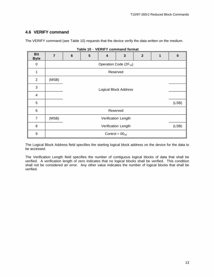
4.6 VERIFY command
The VERIFY command (see Table 10) requests that the device verify the data written on the medium.
Table 10 −− VERIFY command formatBit
Byte7 6 5 4 3 2 1 0
0 Operation Code (2F16)
1 Reserved
2 (MSB)
3 Logical Block Address
4
5 (LSB)
6 Reserved
7 (MSB) Verification Length
8 Verification Length (LSB)
9 Control = 0016
The Logical Block Address field specifies the starting logical block address on the device for the data tobe accessed.
The Verification Length field specifies the number of contiguous logical blocks of data that shall beverified. A verification length of zero indicates that no logical blocks shall be verified. This conditionshall not be considered an error. Any other value indicates the number of logical blocks that shall beverified.

T10/97-260r2 Reduced Block Commands
14
4.7 MODE SELECT/SENSE page parameters
The RBC Device Parameters page (see Table 11) is intended to provide general configurationinformation and to allow modification of that configuration where necessary. The symbol (c) contained ina field or bit indicates that the value may be changed and saved.
Table 11 −− RBC device parameters page format (0616)Bit
Byte7 6 5 4 3 2 1 0
0 PS = 1 Rsvd Page Code (0616)
1 Page Length (0816)
2 Reserved WCD (c)
3 (MSB) Logical Block Size
4 Logical Block Size (LSB)
5 (MSB) Number of Logical Blocks (c)
6
7
8
9 Number of Logical Blocks (c) (LSB)
A Write Cache Disable (WCD) bit of zero specifies that the device server may return GOOD status for aWRITE command after successfully receiving the data and prior to having successfully written it to themedium. A WCD bit of one specifies that the device shall return GOOD status for a WRITE commandafter successfully writing all of the data to the medium.
The Logical Block Size field indicates the number of user data bytes contained in a logical block.
The Number of Logical Blocks field indicates the number of logical blocks contained in the user dataarea.
NOTE − The default Number of Logical Blocks value may be obtained by requesting theDefault Mode Sense data for this page. The current Number of Logical Blocks value maybe obtained by requesting the Saved Mode Sense for this page.


T10/97-260r2 Reduced Block Commands
15
5 SPC-2 implementation requirements for RBC devices
RBC devices require several commands defined in SPC-2 to function in a system. Support for variousbits and fields contained in those commands listed in Table 12 has been restricted in order to conform tothe goal of reduced complexity for RBC devices. Bit and field restrictions are described in the followingclauses.
Table 12 −− RBC required SPC-2 commands
Command name Opcode
INQUIRY 1216
MODE SELECT 5516
MODE SENSE 5A16
TEST UNIT READY 0016
WRITE BUFFER 3B 16
5.1 INQUIRY command
No restrictions are placed on the INQUIRY command for RBC devices.

T10/97-260r2 Reduced Block Commands
16
5.2 MODE SELECT(10) command
The MODE SELECT(10) command provides a means for the initiator to specify device parameters to themass storage device. Devices shall also implement the MODE SENSE(10) command.
Table 13 −− MODE SELECT(10) command formatBit
Byte7 6 5 4 3 2 1 0
0 Operation Code (5516)
1 PF = 1 SP = 1
2 Reserved
3 Reserved
4 Reserved
5 Reserved
6 Reserved
7 (MSB) Parameter list length
8 Parameter list length (LSB)
9 Control = 0016
The Page Format (PF) bit shall be set to one.
The Save Pages (SP) bit shall be set to one, indicating that the device shall perform the specified MODESELECT operation and shall save, to a non-volatile vendor-specific location, all the changeable pages,including any sent with the command.
The device shall NOT validate the non-changeable parameters against the current values that existed forthose mode parameters prior to executing the MODE SELECT command.

T10/97-260r2 Reduced Block Commands
17
5.3 MODE SENSE(10) command
Table 14 −− MODE SENSE(10) command formatBit
Byte7 6 5 4 3 2 1 0
0 Operation Code (5A16)
1 DBD = 1
2 PC Page Code
3 Reserved
4 Reserved
5 Reserved
6 Reserved
7 (MSB) Allocation length
8 Allocation length (LSB)
9 Control = 0016
The Disable Block Descriptors (DBD) bit shall be set to one.
The Page Control (PC) field defines the type of mode parameter values to be returned in the modepages. The Page Control field is defined in Table 15.
Table 15 −− Simple hard disk page control values
Code Type of parameter Support
00b Current Optional
01b Changeable Not supported
10b Default Mandatory
11b Saved Mandatory
NOTE − RBC devices only support Saved and Default parameter values. Since the SPbit is required to be one for the MODE SELECT command, Current and Saved valuesare the same.
A Page Code of 3F16 indicates that all mode pages implemented by the device shall be returned to theinitiator.
5.3.1 Initial response
After a power-up condition or hard reset condition, the device shall respond in the following manner:
T10/97-260r2 Reduced Block Commands
18
a) If default values are requested, report the default values;
b) If saved values are requested, report valid restored mode parameters, or restore the modeparameters and report them. If the saved values of the mode parameters are not able to beaccessed from the non-volatile vendor-specific location, terminate the command with CHECKCONDITION status and set the sense key to NOT READY;
c) If current values are requested, report saved values as described in b).
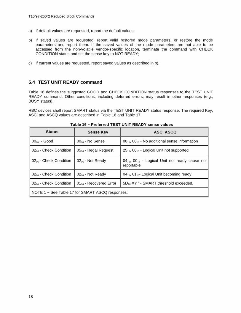
5.4 TEST UNIT READY command
Table 16 defines the suggested GOOD and CHECK CONDITION status responses to the TEST UNITREADY command. Other conditions, including deferred errors, may result in other responses (e.g.,BUSY status).
RBC devices shall report SMART status via the TEST UNIT READY status response. The required Key,ASC, and ASCQ values are described in Table 16 and Table 17.
Table 16 −− Preferred TEST UNIT READY sense values
Status Sense Key ASC, ASCQ
0016 - Good 0016 - No Sense 0016, 0016 - No additional sense information
0216 - Check Condition 0516 - Illegal Request 2516, 0016 - Logical Unit not supported
0216 - Check Condition 0216 - Not Ready 0416, 0016 - Logical Unit not ready cause notreportable
0216 - Check Condition 0216 - Not Ready 0416, 0116- Logical Unit becoming ready
0216 - Check Condition 0116 - Recovered Error 5D16,XY 1 - SMART threshold exceeded,
NOTE 1 − See Table 17 for SMART ASCQ responses.

T10/97-260r2 Reduced Block Commands
19
Table 17 −− SMART ASCQ XY definitions
ASCQ X Description ASCQ Y Description
0 Defined by SPC-2 0 General hard drive failure
1 Hardware impending failure 1 Drive error threshold exceedinglimits
2 Controller impending failure 2 Data error rate exceeding limits
3 Data Channel impending failure 3 Seek error rate exceeding limits
4 Servo impending failure 4 LBA reassignment exceeding limits
5 Spindle impending failure 5 Access times exceeding limits
6 Firmware impending failure 6 Start Unit times exceeding limits
7 Reserved 7 Channel parametrics indicateimpending failure
8 Reserved 8 Controller detected impendingfailure
9 Reserved 9 Throughput performance
A Reserved A Seek time performance
B Reserved B Spin-up retry count
C Reserved C Drive calibration retry count
D Defined by SPC-2 D Reserved
E Defined by SPC-2 E Reserved
F Defined by SPC-2 F Reserved
T10/97-260r2 Reduced Block Commands
20
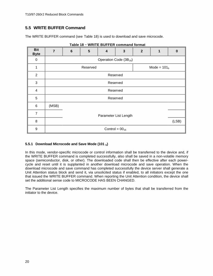
5.5 WRITE BUFFER Command
The WRITE BUFFER command (see Table 18) is used to download and save microcode.
Table 18 −− WRITE BUFFER command formatBit
Byte7 6 5 4 3 2 1 0
0 Operation Code (3B16)
1 Reserved Mode = 101b
2 Reserved
3 Reserved
4 Reserved
5 Reserved
6 (MSB)
7 Parameter List Length
8 (LSB)
9 Control = 0016
5.5.1 Download Microcode and Save Mode (101 b)
In this mode, vendor-specific microcode or control information shall be transferred to the device and, ifthe WRITE BUFFER command is completed successfully, also shall be saved in a non-volatile memoryspace (semiconductor, disk, or other). The downloaded code shall then be effective after each power-cycle and reset until it is supplanted in another download microcode and save operation. When thedownload microcode and save command has completed successfully the device server shall generate aUnit Attention status block and send it, via unsolicited status if enabled, to all initiators except the onethat issued the WRITE BUFFER command. When reporting the Unit Attention condition, the device shallset the additional sense code to MICROCODE HAS BEEN CHANGED.
The Parameter List Length specifies the maximum number of bytes that shall be transferred from theinitiator to the device.

T10/97-260r2 Reduced Block Commands
21
Annex ARBC device implementation guide for SBP-2
A.1 SBP-2 storage model
The SBP-2 Storage Model describes general characteristics and functions of RBC devices whenimplemented using SBP-2. It is intended to provide design information and lead to a better understandingof RBC device functionality.
A.1 .1 Model configurationThis configuration is used only as an example of a common implementation. The following assumptionsare made for this model configuration.
− The device supports a single logical unit.− The device does not support multiple initiators.− The device does not support isochronous data transfers.
Figure A.1 −− Mass storage interface block diagram
A.1 .2 Model operation
The block diagram in Figure A.1 indicates the functional blocks contained in a RBC device that supportsSBP-2. This section describes the function of those blocks when processing a list of ORBs. The ORBscontain READ commands in this example.
After power-on or bus reset, the Command_Agent and Management_Agent engines are in the Resetstate.
The initiator reads the RBC device’s Configuration ROM data in order to determine it’s 1394 capabilities,SBP-2 capabilities, EUI-64 value, command set identifiers, software versions, and Management_AgentCSR address.
The initiator performs a Login operation prior to any request to the RBC device. To perform a Login, the
1394 bus1394
Interface
1394CSRs
Management_AgentEngine
Command_AgentEngine
Execution Engine
DeviceInterfac
e
1394Configuration
ROM

T10/97-260r2 Reduced Block Commands
22
initiator writes its Login ORB address to the Management_Agent register. The Login ORB should containeither the current or master password for the Login to be successful. The RBC device returns the Loginresponse to the bus address specified in the Login ORB. One field of the Login response contains theCommand_Agent’s CSR base address.
Prior to initiating command transfers, the initiator builds a list of Command_Block ORBs in systemmemory. The list may be as short as one ORB, but this example assumes a list length of more than one.The last ORB in the list contains a NULL Next_ORB pointer which indicates the end of the list to the RBCdevice’s Command_Agent fetch engine.
To transition the Command_Agent state from Reset to Active the initiator writes the offset of the firstORB in the ORB list to the RBC device’s ORB_Pointer CSR address. This allows the Command_Agentfetch engine to begin fetching ORBs from initiator memory. If the initiator writes to the Doorbell CSR, theRBC device will ignore the Doorbell at this time.
The RBC device fetches ORBs until its ORB space is full or until an ORB containing a NULL Next_ORBpointer is fetched. Fetched ORBs are routed to the Execution engine. The Execution engine may reorderthe commands contained in the ORBs for best performance.
As each READ command is executed the RBC device transfers READ data to the initiator’s memoryspace via block write requests.
Following the data transfer portion of each command the RBC device writes a Status Block to theinitiator’s Status_FIFO address. The Status_FIFO address for Command Block ORBs is contained in theLogin ORB. The status block contains SBP-2 specific command information as well as general senseinformation.
If an ORB containing a Null Next_ORB pointer is fetched the Execution engine completes all fetchedcommands, including the one in the just fetched ORB, before the Command_Agent transitions to theSuspended state.
If additional commands are to be executed, the initiator creates a new list of Command_Block ORBs;changes the Next_ORB pointer in the last ORB of the old list from NULL to the offset of the first ORB inthe new list; then writes to the RBC device’s Doorbell CSR address. This transitions theCommand_Agent to the Active state.
The RBC device fetches the new Next_ORB pointer value from the last ORB of the old list and beginsfetching ORBS from the new list at that offset.
If the Command_Agent fetch engine has not reached the ORB containing a Null Next_ORB pointer, (andis still in the Active state) the RBC device ignores any writes to the Doorbell CSR address.
This sequence may continue until the RBC device is reset, power is removed, or an error occurs.
A.2 RBC device configuration ROM requirements
Although most Configuration ROM entries are generic, several contain information that is specific toeach device type. Hard disk drive specific Configuration ROM information is defined in this section.
A.2 .1 Unit Directory - Command_Set
The Command_Set entry (key - 3A16) is an immediate entry that, in combination with the
T10/97-260r2 Reduced Block Commands
23
Command_Set_Spec_ID entry specifies the command set supported by the unit.
Command_Set3916
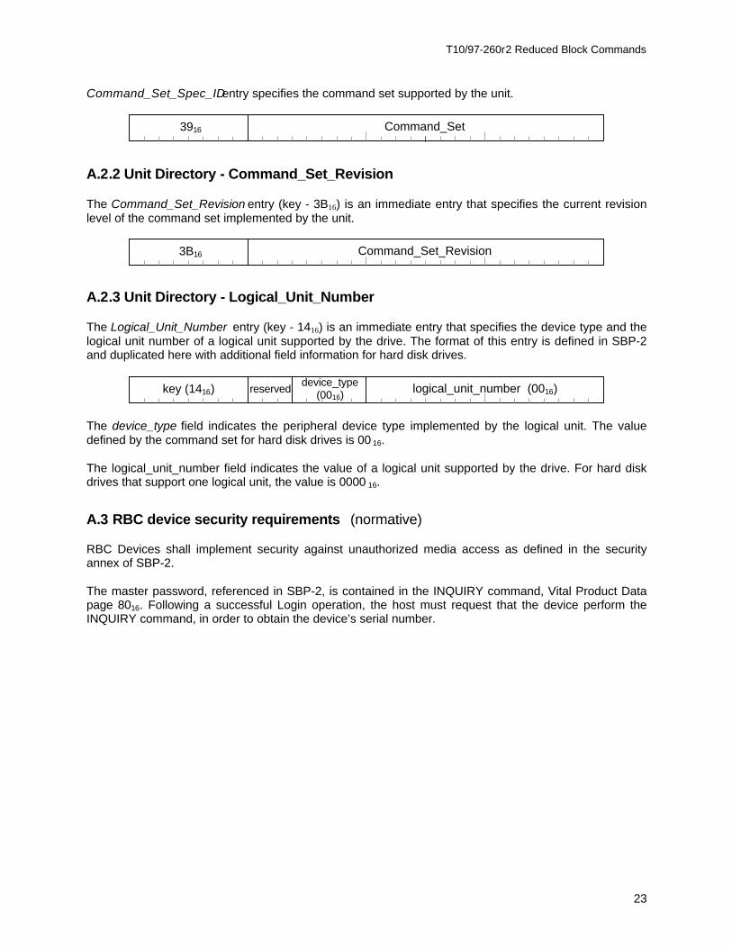
A.2 .2 Unit Directory - Command_Set_Revision
The Command_Set_Revision entry (key - 3B16) is an immediate entry that specifies the current revisionlevel of the command set implemented by the unit.
Command_Set_Revision3B16
A.2 .3 Unit Directory - Logical_Unit_Number
The Logical_Unit_Number entry (key - 1416) is an immediate entry that specifies the device type and thelogical unit number of a logical unit supported by the drive. The format of this entry is defined in SBP-2and duplicated here with additional field information for hard disk drives.
device_type(0016)
logical_unit_number (0016)reservedkey (1416)
The device_type field indicates the peripheral device type implemented by the logical unit. The valuedefined by the command set for hard disk drives is 00 16.
The logical_unit_number field indicates the value of a logical unit supported by the drive. For hard diskdrives that support one logical unit, the value is 0000 16.
A.3 RBC device security requirements (normative)
RBC Devices shall implement security against unauthorized media access as defined in the securityannex of SBP-2.
The master password, referenced in SBP-2, is contained in the INQUIRY command, Vital Product Datapage 8016. Following a successful Login operation, the host must request that the device perform theINQUIRY command, in order to obtain the device’s serial number.

T10/97-260r2 Reduced Block Commands
24
Annex BEvent Status Notification
Previous mass storage device interfaces have been unable to consistently and reliably supportasynchronous event notification. As a substitute, initiators have used the GET EVENT STATUSNOTIFICATION command to acquire asynchronous event status from devices. The GESN commandwas used to either poll the device’s event status or, if the device supported queued commands, theGESN command did not complete until an event occurred. The polling method requires the initiator toprovide a timer in order to repetitively acquire device status. The queued command method requires adevice to process the GESN command in a different manner from all other queued commands. To solvethis problem asynchronous event notification has been made a fundamental part of SBP-2 and RBCdevices.
Through the use of Unsolicited Status, mass storage devices may report asynchronous events themoment that they occur. The initiator need only process the status block to determine the cause of theevent. The device is no longer required to support the GESN command in the polled or queued mode. Itsimply builds and transmits a status block whenever an event occurs.
B.1 Unsolicited status sense definitions
The following table describes unsolicited status sense key and sense code values that may be written toan initiator’s Status_FIFO if the initiator has previously written to the device’s unsolicited_status_enableregister.
Table B.1 −− Unsolicited status sense key/code values
Sensekey
Sensecode
Description
0216 0416 Device Not Ready (reported only on transition or at poweron.)
0616 2816 Not Ready to Ready transition. Medium may have changed.
0616 2916 Power on reset, bus reset, etc.
0616 7F16 Event Status Notification.
Deferred errors may also be reported as unsolicited status.
B.2 Event status sense information
In order to support traditional Event Status Notification through the use of Unsolicited Status, specificStatus, Sense Key, and Sense Code values must be combined.
Status = 0216, Check Condition, indicates that the condition of the device has changed.
Sense Key = 0616, Unit Attention, indicates that an event has occurred that the device mustcommunicate to the initiator.
T10/97-260r2 Reduced Block Commands
25
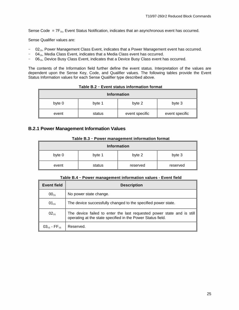
Sense Code = 7F16, Event Status Notification, indicates that an asynchronous event has occurred.
Sense Qualifier values are:
− 0216, Power Management Class Event, indicates that a Power Management event has occurred.− 0416, Media Class Event, indicates that a Media Class event has occurred.− 0616, Device Busy Class Event, indicates that a Device Busy Class event has occurred.
The contents of the Information field further define the event status. Interpretation of the values aredependent upon the Sense Key, Code, and Qualifier values. The following tables provide the EventStatus Information values for each Sense Qualifier type described above.
Table B.2 −− Event status information format
Information
byte 0 byte 1 byte 2 byte 3
event status event specific event specific
B.2 .1 Power Management Information Values
Table B.3 −− Power management information format
Information
byte 0 byte 1 byte 2 byte 3
event status reserved reserved
Table B.4 −− Power management information values - Event field
Event field Description
0016 No power state change.
0116 The device successfully changed to the specified power state.
0216 The device failed to enter the last requested power state and is stilloperating at the state specified in the Power Status field.
0316 - FF16 Reserved.

T10/97-260r2 Reduced Block Commands
26
Table B.5 −− Power management information values - Status field
Status field Description
0016 Reserved.
0116 The device is in the Active state.
0216 The device is in the Idle state.
0316 The device is in the Standby state.
0416 - FF16 Reserved.
B.2 .2 Media event information values
Table B.6 −− Media event information format
Information
byte 0 byte 1 byte 2 byte 3
event status start slot end slot
Table B.7 −− Media event information value - Event field
Event field Description
0016 Media status is unchanged.
0116 Eject request. The user has issued a request to eject the slot or media.
0216 The specified slot has received new media and the media is ready to beaccessed.
0316 Media Removal. The media has been removed from the specified slotand the target is unable to access the media without user intervention.
0416 - FF16 Reserved.
Table B.8 −− Media event information value - Status fieldBit
Byte7 6 5 4 3 2 1 0
1 ReservedMedia
PresentDoor or
TrayOpen

T10/97-260r2 Reduced Block Commands
27
The Door or Tray Open bit indicates the mechanical position of the device’s door or tray. A Door orTray Open value of 1 indicates that the door or tray is open. A value of 0 indicates that the door or trayis closed.
The Media Present bit indicates whether media is installed in the device. A value of 1 indicates thatmedia is present in the device. A value of 0 indicates that no media is present. The Media Present bit isreported independently from the Door or Tray Open bit. If the device cannot report the media state whilethe door or tray is open, this bit shall be set to 0 when the Door or Tray Open bit is 0.
The Start Slot field defines the first slot of a multiple slot device that the media status notificationapplies to. For devices that do not support multiple slots, this field shall be reserved.
The End Slot field defines the last slot of a multiple slot device that the media status notification appliesto. For devices that do not support multiple slots, this field shall be reserved.
B.2 .3 Device Busy Event Information Values
Table B.9 −− Device busy information format
Information
byte 0 byte 1 byte 2 byte 3
event status Time (MSB) Time (LSB)
The Time field is the predicted amount of time remaining for the device to become not busy, in units of100ms.
Table B.10 −− Device busy event information values - Event field
Event field Description
0016 No event is available.
0116 A time-out has occurred.
0216 - FF16 Reserved.
Table B.11 −− Device busy event information values - Status field

T10/97-260r2 Reduced Block Commands
28
Status field Description
0016 No event. The device is ready to accept commands.
0116 The device is in the process of waking up from a lower power state.
0216 The device is in the process of completing an earlier command.
0316 The device is in the process of completing a deferred operation, such asa write.
0416 - FF16 Reserved.