redpaper ibm intellistation power 285 technical overview and introduction
TRANSCRIPT

ibm.com/redbooks Redpaper
Front cover
IBM IntelliStation POWER 285Technical Overview and Introduction
Scott VetterCarlo Costantini
Gregor Linzmeier
Designed for high-end mechanical computer-aided design
Uses leading-edge IBM POWER5+ processor technology
Delivers a 64-bit CATIA capable environment


International Technical Support Organization
IBM IntelliStation POWER 285 Technical Overview and Introduction
September 2006

© Copyright International Business Machines Corporation 2005, 2006. All rights reserved.Note to U.S. Government Users Restricted Rights -- Use, duplication or disclosure restricted by GSA ADP ScheduleContract with IBM Corp.
Second Edition (September 2006)
This edition applies to IBM IntelliStation POWER 285 and IBM AIX 5L Version 5.3, product number 5765-G03.
Note: Before using this information and the product it supports, read the information in “Notices” on page v.

Contents
Notices . . . . . . . . . . . . . . . . . . . . . . . . . . . . . . . . . . . . . . . . . . . . . . . . . . . . . . . . . . . . . . . . . .vTrademarks . . . . . . . . . . . . . . . . . . . . . . . . . . . . . . . . . . . . . . . . . . . . . . . . . . . . . . . . . . . . . . vi
Preface . . . . . . . . . . . . . . . . . . . . . . . . . . . . . . . . . . . . . . . . . . . . . . . . . . . . . . . . . . . . . . . . . viiThe team that wrote this Redpaper . . . . . . . . . . . . . . . . . . . . . . . . . . . . . . . . . . . . . . . . . . . . viiBecome a published author . . . . . . . . . . . . . . . . . . . . . . . . . . . . . . . . . . . . . . . . . . . . . . . . . viiiComments welcome. . . . . . . . . . . . . . . . . . . . . . . . . . . . . . . . . . . . . . . . . . . . . . . . . . . . . . . viii
Chapter 1. General description . . . . . . . . . . . . . . . . . . . . . . . . . . . . . . . . . . . . . . . . . . . . . 11.1 System specifications . . . . . . . . . . . . . . . . . . . . . . . . . . . . . . . . . . . . . . . . . . . . . . . . . . . 21.2 Physical packaging . . . . . . . . . . . . . . . . . . . . . . . . . . . . . . . . . . . . . . . . . . . . . . . . . . . . . 21.3 IntelliStation POWER 285 workstation . . . . . . . . . . . . . . . . . . . . . . . . . . . . . . . . . . . . . . 31.4 Minimum and optional features . . . . . . . . . . . . . . . . . . . . . . . . . . . . . . . . . . . . . . . . . . . . 3
1.4.1 Processor features . . . . . . . . . . . . . . . . . . . . . . . . . . . . . . . . . . . . . . . . . . . . . . . . . 41.4.2 Memory features . . . . . . . . . . . . . . . . . . . . . . . . . . . . . . . . . . . . . . . . . . . . . . . . . . . 51.4.3 Disk and media feature . . . . . . . . . . . . . . . . . . . . . . . . . . . . . . . . . . . . . . . . . . . . . . 51.4.4 USB diskette drive . . . . . . . . . . . . . . . . . . . . . . . . . . . . . . . . . . . . . . . . . . . . . . . . . 51.4.5 USB SpacePilot, SpaceBall, and SpaceMouse . . . . . . . . . . . . . . . . . . . . . . . . . . . 6
1.5 Express product offerings . . . . . . . . . . . . . . . . . . . . . . . . . . . . . . . . . . . . . . . . . . . . . . . . 6
Chapter 2. Architecture and technical overview . . . . . . . . . . . . . . . . . . . . . . . . . . . . . . . 92.1 The POWER5+ processor. . . . . . . . . . . . . . . . . . . . . . . . . . . . . . . . . . . . . . . . . . . . . . . 102.2 Processor and cache . . . . . . . . . . . . . . . . . . . . . . . . . . . . . . . . . . . . . . . . . . . . . . . . . . 112.3 Memory subsystem . . . . . . . . . . . . . . . . . . . . . . . . . . . . . . . . . . . . . . . . . . . . . . . . . . . . 13
2.3.1 Memory placement rules. . . . . . . . . . . . . . . . . . . . . . . . . . . . . . . . . . . . . . . . . . . . 132.3.2 Memory restrictions. . . . . . . . . . . . . . . . . . . . . . . . . . . . . . . . . . . . . . . . . . . . . . . . 142.3.3 Memory throughput . . . . . . . . . . . . . . . . . . . . . . . . . . . . . . . . . . . . . . . . . . . . . . . . 14
2.4 Internal I/O subsystem . . . . . . . . . . . . . . . . . . . . . . . . . . . . . . . . . . . . . . . . . . . . . . . . . 152.4.1 PCI-X slots and adapters . . . . . . . . . . . . . . . . . . . . . . . . . . . . . . . . . . . . . . . . . . . 152.4.2 LAN adapters . . . . . . . . . . . . . . . . . . . . . . . . . . . . . . . . . . . . . . . . . . . . . . . . . . . . 162.4.3 Graphics accelerators . . . . . . . . . . . . . . . . . . . . . . . . . . . . . . . . . . . . . . . . . . . . . . 162.4.4 Flat-panel monitors . . . . . . . . . . . . . . . . . . . . . . . . . . . . . . . . . . . . . . . . . . . . . . . . 192.4.5 Audio adapter . . . . . . . . . . . . . . . . . . . . . . . . . . . . . . . . . . . . . . . . . . . . . . . . . . . . 202.4.6 SCSI adapters. . . . . . . . . . . . . . . . . . . . . . . . . . . . . . . . . . . . . . . . . . . . . . . . . . . . 202.4.7 iSCSI . . . . . . . . . . . . . . . . . . . . . . . . . . . . . . . . . . . . . . . . . . . . . . . . . . . . . . . . . . . 202.4.8 Fibre Channel adapters . . . . . . . . . . . . . . . . . . . . . . . . . . . . . . . . . . . . . . . . . . . . 21
2.5 System ports and serial ports . . . . . . . . . . . . . . . . . . . . . . . . . . . . . . . . . . . . . . . . . . . . 222.6 Internal storage . . . . . . . . . . . . . . . . . . . . . . . . . . . . . . . . . . . . . . . . . . . . . . . . . . . . . . . 22
2.6.1 Internal media devices . . . . . . . . . . . . . . . . . . . . . . . . . . . . . . . . . . . . . . . . . . . . . 222.6.2 Internal hot-swappable SCSI disks . . . . . . . . . . . . . . . . . . . . . . . . . . . . . . . . . . . . 23
2.7 RAID options . . . . . . . . . . . . . . . . . . . . . . . . . . . . . . . . . . . . . . . . . . . . . . . . . . . . . . . . . 242.8 Operating system requirements . . . . . . . . . . . . . . . . . . . . . . . . . . . . . . . . . . . . . . . . . . 242.9 Service processor . . . . . . . . . . . . . . . . . . . . . . . . . . . . . . . . . . . . . . . . . . . . . . . . . . . . . 25
Chapter 3. RAS and manageability . . . . . . . . . . . . . . . . . . . . . . . . . . . . . . . . . . . . . . . . . 273.1 Reliability, fault tolerance, and data integrity. . . . . . . . . . . . . . . . . . . . . . . . . . . . . . . . . 28
3.1.1 Fault avoidance. . . . . . . . . . . . . . . . . . . . . . . . . . . . . . . . . . . . . . . . . . . . . . . . . . . 283.1.2 First-failure data capture . . . . . . . . . . . . . . . . . . . . . . . . . . . . . . . . . . . . . . . . . . . . 283.1.3 Permanent monitoring. . . . . . . . . . . . . . . . . . . . . . . . . . . . . . . . . . . . . . . . . . . . . . 29
© Copyright IBM Corp. 2005, 2006. All rights reserved. iii
3.1.4 Self-healing . . . . . . . . . . . . . . . . . . . . . . . . . . . . . . . . . . . . . . . . . . . . . . . . . . . . . . 303.1.5 N+1 redundancy . . . . . . . . . . . . . . . . . . . . . . . . . . . . . . . . . . . . . . . . . . . . . . . . . . 313.1.6 Fault masking . . . . . . . . . . . . . . . . . . . . . . . . . . . . . . . . . . . . . . . . . . . . . . . . . . . . 313.1.7 Resource deallocation . . . . . . . . . . . . . . . . . . . . . . . . . . . . . . . . . . . . . . . . . . . . . 313.1.8 Serviceability . . . . . . . . . . . . . . . . . . . . . . . . . . . . . . . . . . . . . . . . . . . . . . . . . . . . . 32
3.2 Manageability . . . . . . . . . . . . . . . . . . . . . . . . . . . . . . . . . . . . . . . . . . . . . . . . . . . . . . . . 333.2.1 Service processor . . . . . . . . . . . . . . . . . . . . . . . . . . . . . . . . . . . . . . . . . . . . . . . . . 333.2.2 Service Agent . . . . . . . . . . . . . . . . . . . . . . . . . . . . . . . . . . . . . . . . . . . . . . . . . . . . 343.2.3 IBM IntelliStation POWER 285 firmware maintenance . . . . . . . . . . . . . . . . . . . . . 36
Chapter 4. Workstation hints and tips. . . . . . . . . . . . . . . . . . . . . . . . . . . . . . . . . . . . . . . 374.1 64-bit CATIA . . . . . . . . . . . . . . . . . . . . . . . . . . . . . . . . . . . . . . . . . . . . . . . . . . . . . . . . . 38
4.1.1 Checking the AIX 5L kernel mode . . . . . . . . . . . . . . . . . . . . . . . . . . . . . . . . . . . . 394.1.2 Changing from a 32-bit to a 64-bit kernel . . . . . . . . . . . . . . . . . . . . . . . . . . . . . . . 39
4.2 Checking and changing the SMT setting . . . . . . . . . . . . . . . . . . . . . . . . . . . . . . . . . . . 394.3 Network Installation Management . . . . . . . . . . . . . . . . . . . . . . . . . . . . . . . . . . . . . . . . . 414.4 Automated shutdown . . . . . . . . . . . . . . . . . . . . . . . . . . . . . . . . . . . . . . . . . . . . . . . . . . 434.5 Wake on LAN . . . . . . . . . . . . . . . . . . . . . . . . . . . . . . . . . . . . . . . . . . . . . . . . . . . . . . . . 454.6 AIX Toolbox for Linux . . . . . . . . . . . . . . . . . . . . . . . . . . . . . . . . . . . . . . . . . . . . . . . . . . 464.7 Licence Use Management Version 4.6.8 . . . . . . . . . . . . . . . . . . . . . . . . . . . . . . . . . . . 46
Appendix A. Servicing an IBM IntelliStation system . . . . . . . . . . . . . . . . . . . . . . . . . . . 49Resource Link . . . . . . . . . . . . . . . . . . . . . . . . . . . . . . . . . . . . . . . . . . . . . . . . . . . . . . . . . . . 50IBM Systems Hardware Information Center. . . . . . . . . . . . . . . . . . . . . . . . . . . . . . . . . . . . . 50
Related publications . . . . . . . . . . . . . . . . . . . . . . . . . . . . . . . . . . . . . . . . . . . . . . . . . . . . . 53IBM Redbooks . . . . . . . . . . . . . . . . . . . . . . . . . . . . . . . . . . . . . . . . . . . . . . . . . . . . . . . . . . . 53Other publications . . . . . . . . . . . . . . . . . . . . . . . . . . . . . . . . . . . . . . . . . . . . . . . . . . . . . . . . 53Online resources . . . . . . . . . . . . . . . . . . . . . . . . . . . . . . . . . . . . . . . . . . . . . . . . . . . . . . . . . 54How to get IBM Redbooks . . . . . . . . . . . . . . . . . . . . . . . . . . . . . . . . . . . . . . . . . . . . . . . . . . 54Help from IBM . . . . . . . . . . . . . . . . . . . . . . . . . . . . . . . . . . . . . . . . . . . . . . . . . . . . . . . . . . . 54
iv IBM IntelliStation POWER 285 Technical Overview and Introduction

Notices
This information was developed for products and services offered in the U.S.A.
IBM may not offer the products, services, or features discussed in this document in other countries. Consult your local IBM representative for information on the products and services currently available in your area. Any reference to an IBM product, program, or service is not intended to state or imply that only that IBM product, program, or service may be used. Any functionally equivalent product, program, or service that does not infringe any IBM intellectual property right may be used instead. However, it is the user's responsibility to evaluate and verify the operation of any non-IBM product, program, or service.
IBM may have patents or pending patent applications covering subject matter described in this document. The furnishing of this document does not give you any license to these patents. You can send license inquiries, in writing, to: IBM Director of Licensing, IBM Corporation, North Castle Drive Armonk, NY 10504-1785 U.S.A.
The following paragraph does not apply to the United Kingdom or any other country where such provisions are inconsistent with local law: INTERNATIONAL BUSINESS MACHINES CORPORATION PROVIDES THIS PUBLICATION "AS IS" WITHOUT WARRANTY OF ANY KIND, EITHER EXPRESS OR IMPLIED, INCLUDING, BUT NOT LIMITED TO, THE IMPLIED WARRANTIES OF NON-INFRINGEMENT, MERCHANTABILITY OR FITNESS FOR A PARTICULAR PURPOSE. Some states do not allow disclaimer of express or implied warranties in certain transactions, therefore, this statement may not apply to you.
This information could include technical inaccuracies or typographical errors. Changes are periodically made to the information herein; these changes will be incorporated in new editions of the publication. IBM may make improvements and/or changes in the product(s) and/or the program(s) described in this publication at any time without notice.
Any references in this information to non-IBM Web sites are provided for convenience only and do not in any manner serve as an endorsement of those Web sites. The materials at those Web sites are not part of the materials for this IBM product and use of those Web sites is at your own risk.
IBM may use or distribute any of the information you supply in any way it believes appropriate without incurring any obligation to you.
Information concerning non-IBM products was obtained from the suppliers of those products, their published announcements or other publicly available sources. IBM has not tested those products and cannot confirm the accuracy of performance, compatibility or any other claims related to non-IBM products. Questions on the capabilities of non-IBM products should be addressed to the suppliers of those products.
This information contains examples of data and reports used in daily business operations. To illustrate them as completely as possible, the examples include the names of individuals, companies, brands, and products. All of these names are fictitious and any similarity to the names and addresses used by an actual business enterprise is entirely coincidental.
COPYRIGHT LICENSE: This information contains sample application programs in source language, which illustrates programming techniques on various operating platforms. You may copy, modify, and distribute these sample programs in any form without payment to IBM, for the purposes of developing, using, marketing or distributing application programs conforming to the application programming interface for the operating platform for which the sample programs are written. These examples have not been thoroughly tested under all conditions. IBM, therefore, cannot guarantee or imply reliability, serviceability, or function of these programs. You may copy, modify, and distribute these sample programs in any form without payment to IBM for the purposes of developing, using, marketing, or distributing application programs conforming to IBM's application programming interfaces.
© Copyright IBM Corp. 2005, 2006. All rights reserved. v

TrademarksThe following terms are trademarks of the International Business Machines Corporation in the United States, other countries, or both:
AIX 5L™AIX®Chipkill™eServer™HACMP™IBM®IntelliStation®
POWER5+™POWER5™PowerPC®POWER™pSeries®Redbooks (logo) ™Redbooks™
Resource Link™RS/6000®Service Director™System p5™System p™Wake on LAN®
The following terms are trademarks of other companies:
Power Management, and all Java-based trademarks are trademarks of Sun Microsystems, Inc. in the United States, other countries, or both.
Windows, and the Windows logo are trademarks of Microsoft Corporation in the United States, other countries, or both.
UNIX is a registered trademark of The Open Group in the United States and other countries.
Linux is a trademark of Linus Torvalds in the United States, other countries, or both.
Other company, product, or service names may be trademarks or service marks of others.
vi IBM IntelliStation POWER 285 Technical Overview and Introduction

Preface
This IBM® Redpaper is a comprehensive guide covering the IBM IntelliStation® POWER™ 285 workstation. We introduce major hardware offerings and discuss their prominent functions.
Professionals wanting to acquire a better understanding of IBM IntelliStation systems should consider reading this document. The intended audience for this paper includes:
� Clients� Sales and marketing professionals� Technical support professionals� IBM Business Partners� Independent software vendors
This document is an addition to current set of IBM IntelliStation systems documentation as a desktop reference that offers a detailed, technical description of the IntelliStation POWER 285 system.
This publication does not replace the latest marketing materials, product documentation, and tools. It is intended as an additional source of information that, together with existing sources, can be used to enhance your knowledge of IBM server solutions.
The team that wrote this RedpaperThis Redpaper was produced by an international specialist working at the IBM International Technical Support Organization, Austin Center.
Scott Vetter is a Certified IT Specialist for IBM and has over 21 years of experience with IBM. He currently works in the United States as a presales Systems Architect representing IBM Systems and Technology Group product offerings. He has been working with IBM System p™ servers for over 16 years.
Carlos Costantini is a Certified IT Specialist for IBM and has over 28 years of experience with IBM and IBM Business Partners. He currently works in Italy Presales Field Technical Sales Support for IBM Sales Representatives and IBM Business Partners for all IBM System p offerings. He has broad marketing experience. He is a certified specialist for IBM eServer™ pSeries® and IBM System p servers.
Gregor Linzmeier is an IBM Advisory IT Specialist for IBM System p5™ workstation and entry servers as part of the Systems and Technology Group in Mainz, Germany, supporting IBM sales, Business Partners, and client with pre-sales consultation and implementation of client/server environments. He has worked for more than 15 years as an infrastructure specialist for RT, RS/6000®, pSeries, and IBM AIX® 5L™ in large CATIA client/server projects.
The project that produced this document was managed by:
Scott VetterIBM U.S.
© Copyright IBM Corp. 2005, 2006. All rights reserved. vii

Thanks to the following people for their contributions to this project:
Thoi Nguyen, Jan Palmer, Hal Jennings, Terry J. Brennan, Pat Buckland, George L. More, Gary Hornyak, John Hilburn, Bill Mihaltse, Doug SzerdiIBM U.S.
Volker HaugIBM Germany
Become a published authorJoin us for a two- to six-week residency program! Help write an IBM Redbook dealing with specific products or solutions, while getting hands-on experience with leading-edge technologies. You'll team with IBM technical professionals, Business Partners or clients.
Your efforts will help increase product acceptance and customer satisfaction. As a bonus, you'll develop a network of contacts in IBM development labs, and increase your productivity and marketability.
Find out more about the residency program, browse the residency index, and apply online at:
ibm.com/redbooks/residencies.html
Comments welcomeYour comments are important to us!
We want our papers to be as helpful as possible. Send us your comments about this Redpaper or other Redbooks™ in one of the following ways:
� Use the online Contact us review redbook form found at:
ibm.com/redbooks
� Send your comments in an email to:
� Mail your comments to:
IBM Corporation, International Technical Support OrganizationDept. JN9B Building 90511501 Burnet RoadAustin, Texas 78758-3493
viii IBM IntelliStation POWER 285 Technical Overview and Introduction

Chapter 1. General description
The IBM IntelliStation POWER 285 workstation (9111-285) combines excellent performance and capacity in a flexible, affordable package. When used with the IBM POWER GXT4500P or GXT6500P 3D graphics accelerator, it is an outstanding choice for high-end Mechanical Computer Aided Design (MCAD), Computer Aided Engineering (CAE), graphic processing, and other floating-point intensive business and technical applications. Using a 2D graphics accelerator, it can be used for less demanding applications such as software development.
With leading-edge IBM POWER5+™ processor technology, the affordable 64-bit symmetric multiprocessing (SMP) IntelliStation POWER 285 workstation offers significant price and performance benefits. For MCAD workloads, it provides much greater performance than its predecessor, the IntelliStation POWER 275. By extending the performance of high-end design and analysis, the IntelliStation POWER 285 raises the bar for single-seat MCAD design and analysis solutions.
The IntelliStation POWER 285 is available in a 1-core or 2-core configuration using state-of-the-art, 64-bit, copper-based POWER5+ microprocessors running at 1.9 or 2.1GHz, with 36 MB of L3 cache. The base 1 GB of main memory can be expanded to 32 GB for improved performance and exploitation of 64-bit addressing used in large computational applications.
The IntelliStation POWER 285 contains seven bays, four of the bays are front-accessible and hot-swap-capable DASD bays. These four DASD bays can accommodate up to 1.2 TB of disk storage. Two of the remaining three bays are used for a DVD-ROM and a DVD-RAM, and the last bay can contain a tape drive.
The IntelliStation POWER 285 workstation supports a full range of graphic input and output devices including the USB IBM SpacePilot, SpaceBall Plus 3D, and USB SpaceMouse Plus 3D input devices, flat panel monitors, and other keyboard and mouse devices.
Additional reliability and availability features include redundant hot-plug cooling fans. Along with these hot-plug components, the IntelliStation POWER 285 is designed to provide an extensive set of reliability, availability, and serviceability (RAS) features that include improved fault isolation, recovery from errors without stopping the system, avoidance of recurring failures, and predictive failure analysis.
1
© Copyright IBM Corp. 2005, 2006. All rights reserved. 1
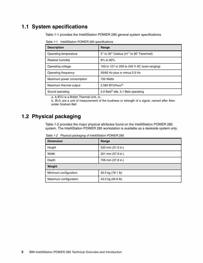
1.1 System specificationsTable 1-1 provides the IntelliStation POWER 285 general system specifications.
Table 1-1 IntelliStation POWER 285 specifications
1.2 Physical packagingTable 1-2 provides the major physical attributes found on the IntelliStation POWER 285 system. The IntelliStation POWER 285 workstation is available as a deskside system only.
Table 1-2 Physical packaging of IntelliStation POWER 285
Description Range
Operating temperature 5° to 35° Celsius (41° to 95° Farenheit)
Relative humidity 8% to 80%
Operating voltage 100 to 127 or 200 to 240 V AC (auto-ranging)
Operating frequency 50/60 Hz plus or minus 0.5 Hz
Maximum power consumption 750 Watts
Maximum thermal output 2.560 BTU/houra
a. A BTU is a British Thermal Unit, or .
Sound operating 5.0 Belsb idle, 5.1 Bels operating
b. Bels are a unit of measurement of the loudness or strength of a signal, named after Alex-ander Graham Bell
Dimension Range
Height 533 mm (21.0 in.)
Width 201 mm (07.9 in.)
Depth 706 mm (27.8 in.)
Weight
Minimum configuration 35.5 kg (78.1 lb)
Maximum configuration 43.0 kg (94.6 lb)
2 IBM IntelliStation POWER 285 Technical Overview and Introduction

1.3 IntelliStation POWER 285 workstationFigure 1-1 shows a detailed view of the IntelliStation POWER 285 workstation, including the locations of all components and devices. Note especially the improved front access doors and acoustic materials used.
Figure 1-1 Front three-quarters view of IntelliStation POWER 285
1.4 Minimum and optional featuresThe IntelliStation POWER 285 system is based on a flexible, modular design of one POWER5+ processor packaged in a dual-core module (DCM) and an integrated L3 cache, soldered directly to the system board. The minimum IntelliStation POWER 285 configuration must include a processor, a processor entitlement, memory, power supply, hard disk, a disk drive enclosure, a media backplane, a power cord, and a 2D graphics accelerator.
The major features of the IntelliStation POWER 285 are:
� 1-core and 2-core configurations, both available with 1.9 GHz or 2.1GHz POWER5+ processors featuring a 36 MB L3 cache
� From 1 GB to 32 GB of total system memory capacity using DDR-2 DIMM technology
� Four SCSI disk drives in a minimum configuration for a total internal storage capacity of 1.2 TB using 300 GB disk drives
Chapter 1. General description 3
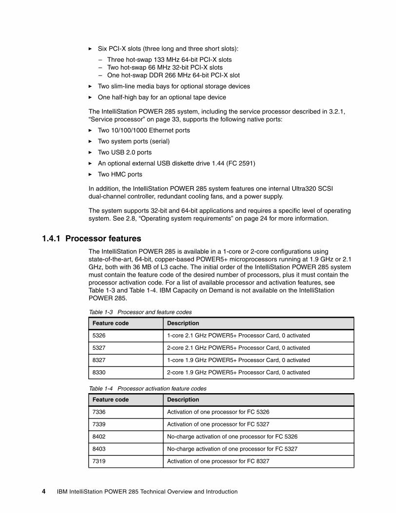
� Six PCI-X slots (three long and three short slots):
– Three hot-swap 133 MHz 64-bit PCI-X slots– Two hot-swap 66 MHz 32-bit PCI-X slots– One hot-swap DDR 266 MHz 64-bit PCI-X slot
� Two slim-line media bays for optional storage devices
� One half-high bay for an optional tape device
The IntelliStation POWER 285 system, including the service processor described in 3.2.1, “Service processor” on page 33, supports the following native ports:
� Two 10/100/1000 Ethernet ports
� Two system ports (serial)
� Two USB 2.0 ports
� An optional external USB diskette drive 1.44 (FC 2591)
� Two HMC ports
In addition, the IntelliStation POWER 285 system features one internal Ultra320 SCSI dual-channel controller, redundant cooling fans, and a power supply.
The system supports 32-bit and 64-bit applications and requires a specific level of operating system. See 2.8, “Operating system requirements” on page 24 for more information.
1.4.1 Processor featuresThe IntelliStation POWER 285 is available in a 1-core or 2-core configurations using state-of-the-art, 64-bit, copper-based POWER5+ microprocessors running at 1.9 GHz or 2.1 GHz, both with 36 MB of L3 cache. The initial order of the IntelliStation POWER 285 system must contain the feature code of the desired number of processors, plus it must contain the processor activation code. For a list of available processor and activation features, see Table 1-3 and Table 1-4. IBM Capacity on Demand is not available on the IntelliStation POWER 285.
Table 1-3 Processor and feature codes
Table 1-4 Processor activation feature codes
Feature code Description
5326 1-core 2.1 GHz POWER5+ Processor Card, 0 activated
5327 2-core 2.1 GHz POWER5+ Processor Card, 0 activated
8327 1-core 1.9 GHz POWER5+ Processor Card, 0 activated
8330 2-core 1.9 GHz POWER5+ Processor Card, 0 activated
Feature code Description
7336 Activation of one processor for FC 5326
7339 Activation of one processor for FC 5327
8402 No-charge activation of one processor for FC 5326
8403 No-charge activation of one processor for FC 5327
7319 Activation of one processor for FC 8327
4 IBM IntelliStation POWER 285 Technical Overview and Introduction

1.4.2 Memory featuresThe system board of the IntelliStation POWER 285 system has eight sockets for memory DIMMs. The minimum memory requirement is 1 GB, and the maximum capacity is 32 GB. Table 1-5 lists the available memory features.
Table 1-5 Memory sizes and feature codes
1.4.3 Disk and media featureThe IntelliStation POWER 285 configuration includes a 4-pack disk drive enclosure. The IntelliStation POWER 285 workstation features up to four disk drive bays, two slim-line media device bays, and one half-height media bay. The minimum configuration requires at least one disk drive. Table 1-6 shows the disk drive feature codes that each bay can contain.
Table 1-6 Disks drives and feature codes
1.4.4 USB diskette driveIn some situations, an external USB 1.44 MB diskette drive for the IntelliStation POWER 285 system (FC 2591) is helpful. This lightweight USB V2 attached diskette drive takes its power requirements from the USB port. A USB cable is provided. The drive can be attached to the integrated USB ports, or to a USB adapter (FC 2738). A maximum of one USB diskette drive is supported per controller. The same controller can share a USB mouse and keyboard.
7320 Activation of one processor for FC 8330
8409 No-charge activation of one processor for FC 8327
8410 No-charge activation of one processor for FC 8330
Feature code Description
Feature code Description
1930 1 GB (2 x 512 MB), DIMMS, 533 MHz DDR-2 SDRAM
1931 2 GB (2 x 1024 MB), DIMMS, 533 MHz DDR-2 SDRAM
1932 4 GB (2 x 2048 MB), DIMMS, 533 MHz DDR-2 SDRAM
1934 8 GB (2 x 4096 MB), DIMMS, 533 MHz DDR-2 SDRAM
Feature code Description
1970 36.4 GB 15 K RPM Ultra320 SCSI Disk Drive Assembly
1968 73.4 GB 10 K RPM Ultra320 SCSI Disk Drive Assembly
1971 73.4 GB 15 K RPM Ultra320 SCSI Disk Drive Assembly
1969 146.8 GB 10 K RPM Ultra320 SCSI Disk Drive Assembly
1972 146.8 GB 15 K RPM Ultra320 SCSI Disk Drive Assembly
1973 300 GB 10 K RPM Ultra320 SCSI Disk Drive Assembly
Chapter 1. General description 5
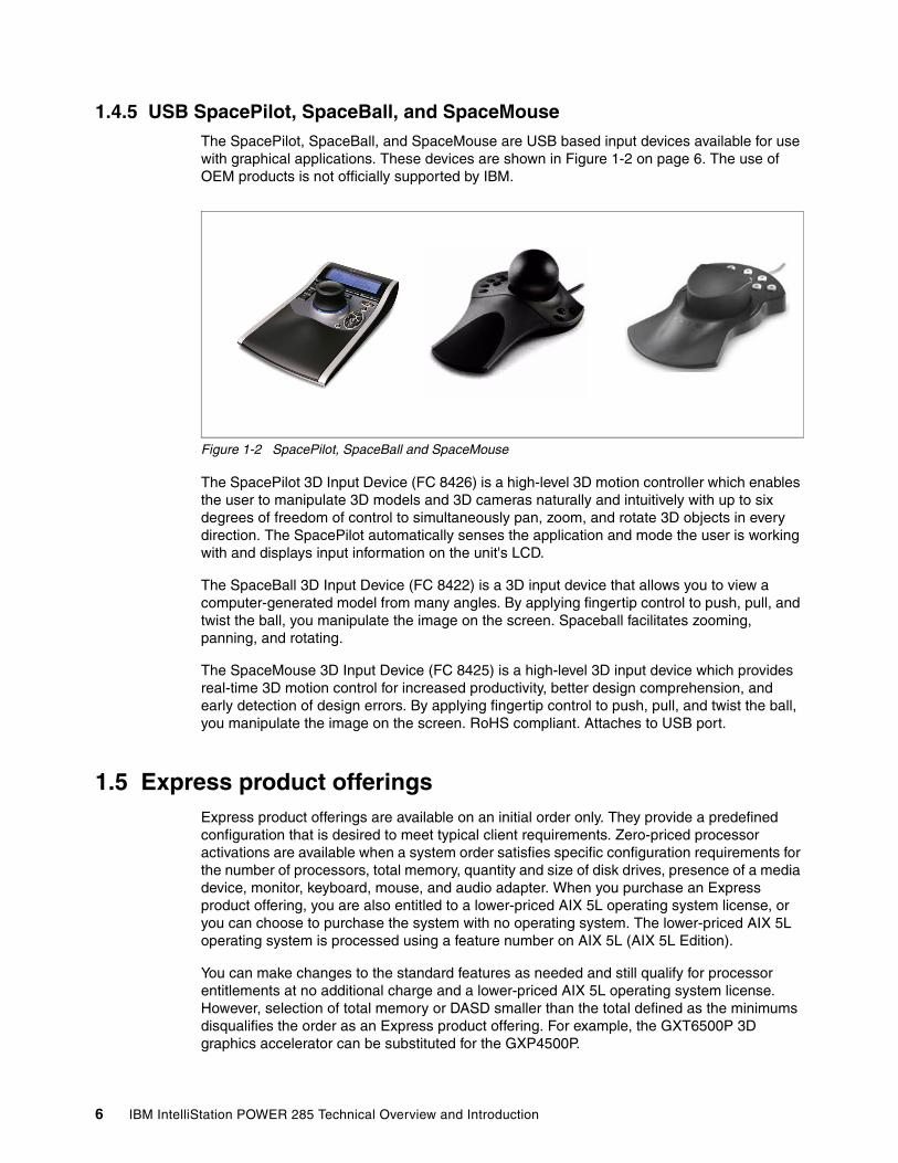
1.4.5 USB SpacePilot, SpaceBall, and SpaceMouseThe SpacePilot, SpaceBall, and SpaceMouse are USB based input devices available for use with graphical applications. These devices are shown in Figure 1-2 on page 6. The use of OEM products is not officially supported by IBM.
Figure 1-2 SpacePilot, SpaceBall and SpaceMouse
The SpacePilot 3D Input Device (FC 8426) is a high-level 3D motion controller which enables the user to manipulate 3D models and 3D cameras naturally and intuitively with up to six degrees of freedom of control to simultaneously pan, zoom, and rotate 3D objects in every direction. The SpacePilot automatically senses the application and mode the user is working with and displays input information on the unit's LCD.
The SpaceBall 3D Input Device (FC 8422) is a 3D input device that allows you to view a computer-generated model from many angles. By applying fingertip control to push, pull, and twist the ball, you manipulate the image on the screen. Spaceball facilitates zooming, panning, and rotating.
The SpaceMouse 3D Input Device (FC 8425) is a high-level 3D input device which provides real-time 3D motion control for increased productivity, better design comprehension, and early detection of design errors. By applying fingertip control to push, pull, and twist the ball, you manipulate the image on the screen. RoHS compliant. Attaches to USB port.
1.5 Express product offeringsExpress product offerings are available on an initial order only. They provide a predefined configuration that is desired to meet typical client requirements. Zero-priced processor activations are available when a system order satisfies specific configuration requirements for the number of processors, total memory, quantity and size of disk drives, presence of a media device, monitor, keyboard, mouse, and audio adapter. When you purchase an Express product offering, you are also entitled to a lower-priced AIX 5L operating system license, or you can choose to purchase the system with no operating system. The lower-priced AIX 5L operating system is processed using a feature number on AIX 5L (AIX 5L Edition).
You can make changes to the standard features as needed and still qualify for processor entitlements at no additional charge and a lower-priced AIX 5L operating system license. However, selection of total memory or DASD smaller than the total defined as the minimums disqualifies the order as an Express product offering. For example, the GXT6500P 3D graphics accelerator can be substituted for the GXP4500P.
6 IBM IntelliStation POWER 285 Technical Overview and Introduction

Four Express product offerings are available for the IntelliStation POWER 285 system, as shown in Table 1-7 on page 7 through Table 1-10 on page 8.
Build-to-order is also available, allowing you to select the exact features you require.
Table 1-7 Express offering 190W
Table 1-8 Express offering 290W
Express offering 190W with one processor activation
Feature code Description
83271930 x 2196819942842364451707877657488xx88418409 x1
1-core 1.9 GHz POWER5+ processor1024 MB (2 x 512 MB) DIMMs73.4 GB 10k disk driveDVD-ROMGXT4500P graphics acceleratorT119 Flat Panel MonitorPower supply, 700 wattMedia backplane4-pack disk drive enclosureQuiet touch keyboard, USB3-button optical mouseZero-priced express activations
Express offering 290W with one processor activation
Feature code Description
833073201930 x 41968 x 219942842364451707877657488xx88417320 x 18410 x 1
2-core 1.9 GHz POWER5+ processorProcessor entitlement1024 MB (2 x 512 MB) DIMMs73.4 GB 10k disk driveDVD-ROMGXT4500P graphics acceleratorT119 Flat Panel MonitorPower supply, 700 wattMedia backplane4-pack disk drive enclosureQuiet touch keyboard, USB3-button optical mouseProcessor entitlementZero-priced express activations
Chapter 1. General description 7
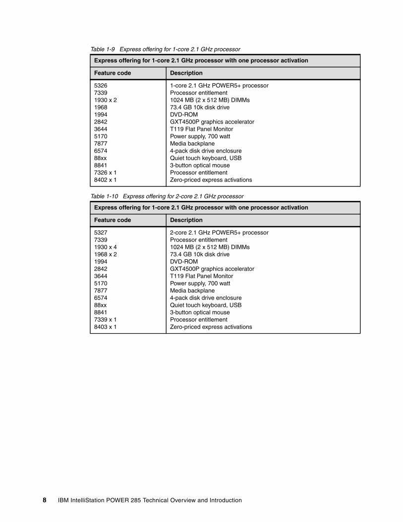
Table 1-9 Express offering for 1-core 2.1 GHz processor
Table 1-10 Express offering for 2-core 2.1 GHz processor
Express offering for 1-core 2.1 GHz processor with one processor activation
Feature code Description
532673391930 x 2196819942842364451707877657488xx88417326 x 18402 x 1
1-core 2.1 GHz POWER5+ processorProcessor entitlement1024 MB (2 x 512 MB) DIMMs73.4 GB 10k disk driveDVD-ROMGXT4500P graphics acceleratorT119 Flat Panel MonitorPower supply, 700 wattMedia backplane4-pack disk drive enclosureQuiet touch keyboard, USB3-button optical mouseProcessor entitlementZero-priced express activations
Express offering for 1-core 2.1 GHz processor with one processor activation
Feature code Description
532773391930 x 41968 x 219942842364451707877657488xx88417339 x 18403 x 1
2-core 2.1 GHz POWER5+ processorProcessor entitlement1024 MB (2 x 512 MB) DIMMs73.4 GB 10k disk driveDVD-ROMGXT4500P graphics acceleratorT119 Flat Panel MonitorPower supply, 700 wattMedia backplane4-pack disk drive enclosureQuiet touch keyboard, USB3-button optical mouseProcessor entitlementZero-priced express activations
8 IBM IntelliStation POWER 285 Technical Overview and Introduction
Chapter 2. Architecture and technical overview
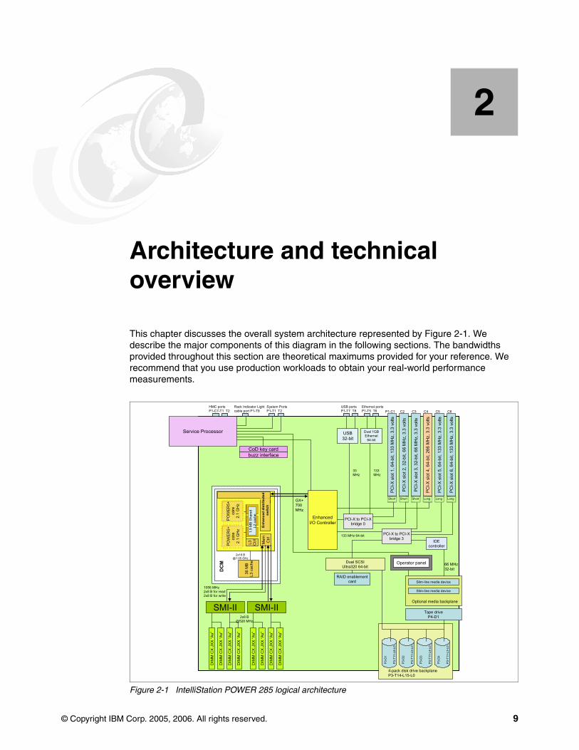
This chapter discusses the overall system architecture represented by Figure 2-1. We describe the major components of this diagram in the following sections. The bandwidths provided throughout this section are theoretical maximums provided for your reference. We recommend that you use production workloads to obtain your real-world performance measurements.
Figure 2-1 IntelliStation POWER 285 logical architecture
2
EnhancedI/O Controller
GX+700 MHz
Service Processor
System PortsP1-T1 T2
HMC portsP1-C7-T1 T2
Rack Indicator Light cable port P1-T9
CoD key cardbuzz interface
USB portsP1-T7 T8
Ethernet portsP1-T5 T6
USB32-bit
Dual 1GBEthernet
64-bit
PC
I-X s
lot 1
, 64-
bit,
133
MH
z, 3
.3 v
olts
PC
I-X s
lot 2
, 32-
bit,
66 M
Hz,
3.3
vol
ts
PC
I-X s
lot 3
, 32-
bit,
66 M
Hz,
3.3
vol
ts
PC
I-X s
lot 4
, 64-
bit,
266
MH
z, 3
.3 v
olts
PC
I-X s
lot 5
, 64-
bit,
133
MH
z, 3
.3 v
olts
Short Long LongShort Short
PCI-X to PCI-Xbridge 0
133 MHz
33 MHz
PCI-X to PCI-Xbridge 3
IDEcontroller
133 MHz 64-bit
Dual SCSIUltra320 64-bit
4-pack disk drive backplaneP3-T14-L15-L0
Tape driveP4-D1
Optional media backplane
Slim-line media device
Slim-line media device
Operator panel
P1-C1 C2 C3 C4 C5
P3-D
1
P3-D
2
P3-D
3
P3-D
4
P3-T
11-L
8-L0
P3-T
11-L
5-L0
P3-T
11-L
4-L0
P3-T
11-L
3-L0
66 MHz32-bit
PO
WE
R5+
core
2.1
GH
z
PO
WE
R5+
core
2.1
GH
z
PO
WE
R5+
core
2.1
GH
z
PO
WE
R5+
core
2.1
GH
z
1.9
MB
Sha
red
L2 c
ache
L3 Ctrl Mem Ctrl
DC
M
Enha
nced
dis
trib
uted
sw
itch
SMI-II SMI-II
1056 MHz2x8 B for read2x8 B for write
DIM
M C
X JX
X “A
x”
DIM
M C
X JX
X “A
x”
DIM
M C
X JX
X “A
x”
DIM
M C
X JX
X “A
x”
DIM
M C
X JX
X “A
x”
DIM
M C
X JX
X “A
x”
DIM
M C
X JX
X “A
x”
DIM
M C
X JX
X “A
x”
2x8 B@528 MHz
36 M
BL3
cac
he
2x16 [email protected] GHz
PC
I-X s
lot 6
, 64-
bit,
133
MH
z, 3
.3 v
olts
Long
C6
RAID enablementcard
© Copyright IBM Corp. 2005, 2006. All rights reserved. 9

2.1 The POWER5+ processorThe IBM POWER5+ processor capitalizes all the enhancements brought by the POWER5™ processor. For a detailed description of the POWER5 processor, refer to IBM IntelliStation POWER 285 Technical Overview and Introduction, REDP-4078. Figure 2-2 shows a high-level view of the POWER5+ processor.
Figure 2-2 Power5+ processor
The CMOS10S technology in the POWER5+ processor uses a 90 nm fabrication process, which enables:
� Performance gains through faster clock rates� Processor size reduction (243 mm compared with 389 mm)
The POWER5+ processor is 37% smaller than the POWER5 processor. It consumes less power and requires less sophisticated cooling. Thus, you can use the POWER5+ processor in servers where previously you could only use low frequency processors because of cooling restrictions.
The POWER5+ design provides the following additional enhancements:
� New page sizes added in ERAT and TLB
Two new pages sizes (64 KB and 16 GB) were recently added in PowerPC® architecture.
� A new segment size available in SLB
One new 1 TB segment size was recently added in PowerPC architecture.
Core2.1 GHz
Core2.1 GHz
Core 2.1 GHzCore
2.1 GHz
1.9 MB L2L3Intf
MemCntrl
GX+Intf
SMPFabric
Bus
L3Bus
MemBus
GX+Bus
VerticalFabricBus
POWER 5+ Processor
Enhanced Distributed Switch(Fabric Bus Controller)
10 IBM IntelliStation POWER 285 Technical Overview and Introduction
� The TLB size doubled in the POWER5+ over the POWER5 processors
The TLB in POWER5+ has 2048 entries.
� Floating-point round to integer instructions
New instructions (frfin, frfiz, frfip, frfim) have been added to round floating-point numbers integers with the following rounding modes: nearest, zero, integer plus, integer minus.
� Improved floating-point performance
� Lock performance enhancement
� Enhanced SLB read
� True Little-Endian mode
This is support for the True Little-Endian mode as defined in the PowerPC architecture.
� Double the SMP support
Changes have been made in the fabric, L2 and L3 controller, memory controller, GX controller and processor RAS to provide support for the QCM that allows the SMP system sizes to be double that is available in POWER5 DCM-based servers. Current POWER5+ implementations only supports single address loop.
� Several enhancements in the memory controller for improved performance
The controller comes ready to support for DDR-2 667 MHz DIMMs in the future.
� Enhanced redundancy in L1 cache, L2 cache and L3 directory
Independent control of the L2 cache and the L3 directory for redundancy to allow split-repair action has been added. More word line redundancy has been added in the L1 Dcache. In addition, Array Built-In Self Test (ABIST) column repair for the L2 cache and the L3 directory has been added.
2.2 Processor and cache In the IntelliStation POWER 285 system, the POWER5+ processor has been packaged with the L3 cache chip into a cost-effective, dual-core module (DCM) package. The storage structure for the POWER5+ processor is a distributed memory architecture that provides high memory bandwidth. The DCM and its optional L3 cache are directly soldered to the system board. They are interfaced to eight memory slots, controlled by two Synchronous Memory Interface (SMI-II) controllers that are in close physical proximity to the DCM. The IntelliStation POWER 285 system supports one POWER5+ microprocessor with either one or two active cores sharing the integrated 36 L3 cache. See Figure 2-3 on page 12 for a POWER5+ processor core layout view.
Chapter 2. Architecture and technical overview 11

Figure 2-3 Two-core processor with DDR-2 memory socket layout view
Available processor speedsThe IntelliStation POWER 285 operates at a processor clock rate of 1.9 or 2.1 GHz for 1-core and 2-core systems. To determine the processor characteristics on a running system, use one of the following AIX 5L commands:
� lsattr -El procX
Where X is the number of the processors, for example, proc0 is the first processor in the system. The output from the command would be similar to the output in Example 2-1. False, as used in this output, signifies that the value cannot be changed through an AIX 5L command interface.
Example 2-1 Output from lsattr -El procX command
type powerPC_POWER5 Processor type Falsefrequency 1896102000 Processor Speed Falsesmt_enabled true Processor SMT enabled Falsesmt_threads 2 Processor SMT threads Falsestate enable Processor state False
� pmcycles -m
This command uses the performance monitor cycle counter and the processor real-time clock to measure the actual processor clock speed in MHz. The output in Example 2-2 is from a 2-core IntelliStation POWER 285 system running at 1.9 GHz with simultaneous multithreading functionality enabled.
Example 2-2 Output from pmcycles -m command
Cpu 0 runs at 1896 MHzCpu 1 runs at 1896 MHzCpu 2 runs at 1896 MHzCpu 3 runs at 1896 MHz
Note: The pmcycles command is part of the bos.pmapi fileset. First check whether that component is installed using the lslpp -l bos.pmapi command.
POWER5+core
2.1 GHz
POWER5+core
2.1 GHz
1.9 MB Shared L2 cache
L3Ctrl
MemCtrl
36 MBL3 cache
DCM
SMI-II
SMI-II
1056 MHz2 x 8 B for read2 x 2 B for write
DIMM
DIMM
DIMM
DIMM
DIMM
DIMM
DIMM
DIMM
2 x 8 B@528 MHz
GX+Ctrl
Enhanced distributed switch
GX+BusPOWER5+
core2.1 GHz
POWER5+core
2.1 GHz
POWER5+core
2.1 GHz
POWER5+core
2.1 GHz
1.9 MB Shared L2 cache
L3Ctrl
MemCtrl
36 MBL3 cache
DCM
SMI-II
SMI-II
1056 MHz2 x 8 B for read2 x 2 B for write
DIMM
DIMM
DIMM
DIMM
DIMM
DIMM
DIMM
DIMM
2 x 8 B@528 MHz
GX+Ctrl
Enhanced distributed switch
GX+Bus
12 IBM IntelliStation POWER 285 Technical Overview and Introduction
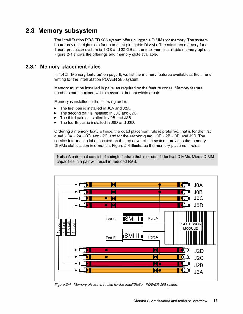
2.3 Memory subsystemThe IntelliStation POWER 285 system offers pluggable DIMMs for memory. The system board provides eight slots for up to eight pluggable DIMMs. The minimum memory for a 1-core processor system is 1 GB and 32 GB as the maximum installable memory option. Figure 2-4 shows the offerings and memory slots available.
2.3.1 Memory placement rulesIn 1.4.2, “Memory features” on page 5, we list the memory features available at the time of writing for the IntelliStation POWER 285 system.
Memory must be installed in pairs, as required by the feature codes. Memory feature numbers can be mixed within a system, but not within a pair.
Memory is installed in the following order:
� The first pair is installed in J0A and J2A. � The second pair is installed in J0C and J2C. � The third pair is installed in J0B and J2B � The fourth pair is installed in J0D and J2D.
Ordering a memory feature twice, the quad placement rule is preferred, that is for the first quad, J0A, J2A, J0C, and J2C, and for the second quad, J0B, J2B, J0D, and J2D. The service information label, located on the top cover of the system, provides the memory DIMMs slot location information. Figure 2-4 illustrates the memory placement rules.
Figure 2-4 Memory placement rules for the IntelliStation POWER 285 system
Note: A pair must consist of a single feature that is made of identical DIMMs. Mixed DIMM capacities in a pair will result in reduced RAS.
J2CJ2B
J2D
J2A
J0D
J0BJ0C
J0A
SMI II
SMI II PROCESSOR
MODULE
Port A
Port APort B
Port B
4th
pai
r 2
nd p
air
3rd
pai
r 1
st p
air
Chapter 2. Architecture and technical overview 13

2.3.2 Memory restrictions
Examine the label for verification of IBM memory. All IBM memory is identified by an IBM logo and a white label printed with a barcode on the top and an alphanumeric string on the bottom, created according to the rule reported in Figure 2-5.
Figure 2-5 IBM memory certification label
Sometimes, OEM vendors put a label reporting the IBM memory part number, but not the barcode or the alphanumeric string, or both, on their DIMMs.
In the event of a system failure caused by OEM memory installed in the system, the first recourse is to replace the suspected memory with IBM memory then check whether the problem is corrected. Contact your IBM representative for further assistance, if needed.
2.3.3 Memory throughputThe memory subsystem throughput is based on the speed of the memory. An elastic interface, contained in the POWER5+ processor, buffers reads and writes to and from memory and the processor. There are two Synchronous Memory Interface (SMI-II) chips, each with a single 8-byte read and 2-byte write high-speed Elastic Interface-II bus to the processor memory controller. The bus allows double reads or writes per clock cycle. Because the bus operates at 1066 MHz, the peak processor-to-memory throughput for read is (8 x 2 x 1056) = 16896 MBps or 16.89. The peak processor-to-memory throughput for write is (2 x 2 x 1056) = 4224 MBps or 4.22 GBps, making total 21.12 GBps.
The 533 MHz DDR2 memory DIMMS operate at 528 MHz through four 8-byte paths. Read and write operations share these paths. There must be at least four DIMMs installed to effectively use each path. In this case, the throughput between the SMI-II and the DIMMs is (8 x 4 x 528) or 16.89 GBps.
These values are maximum theoretical throughputs for comparison purposes only. Table 2-1 on page 15 provides the theoretical throughputs values for different configurations.
Attention: Only use IBM memory in IBM System p servers. The IntelliStation POWER 285 system does not support original equipment manufacturer (OEM) memory. There is no exception to this rule. OEM memory is never certified for the use in IBM System p servers. If the IntelliStation POWER 285 system is populated with OEM memory, you might experience unexpected and unpredictable behavior.
11S1234567YL12345678901 FRU P/N EC Level
Seven digitsIBM part number
Twelve digitsIBM plant identificatorand part serial number
separator
14 IBM IntelliStation POWER 285 Technical Overview and Introduction

Table 2-1 Theoretical throughput rates
2.4 Internal I/O subsystemThe internal I/O subsystem resides on the system board, and the flexible service processor (FSP) is packaged on a separate service processor card. The system board contains the Enterprise hub and the PCI-X host bridge chips to connect to the integrated I/O packaged on the system board. Two ports of the Enterprise hub chip are used for the integrated I/O, and the remaining two ports are routed to external connectors.
The system board provides six PCI-X slots and several integrated PCI devices that interface the two PCI-X-to-PCI-X bridges to the primary PCI-X buses on the PCI-X host bridge chip.
PCI-X slots 1, 2, and 3 can accept short PCI-X or PCI cards only. The remaining three PCI-X slots are full length cards. The dual 1 Gb Ethernet controller is integrated on the system board.
2.4.1 PCI-X slots and adaptersPCI-X, where the X stands for extended, is an enhanced PCI bus, delivering a bandwidth of up to 2 GBps, running a 64-bit bus at 266 MHz. PCI-X is backward compatible, so the IntelliStation POWER 285 system can support existing 3.3 volt PCI adapters.
The slots have the following attributes:
� Three hot-swap 133 MHz 64-bit PCI-X slots� Two hot-swap 66 MHz 32-bit PCI-X slots� One hot-swap DDR 266 MHz 64-bit PCI-X slot
The PCI-X slots in the IntelliStation POWER 285 system support hot-plug and extended error handling (EEH). In the unlikely event of a problem, EEH-enabled adapters respond to a special data packet generated from the affected PCI-X slot hardware by calling system firmware, which will examine the affected bus, allow the device driver to reset it, and continue without a system reboot.
The DDR PCI-X slot provides a high-bandwidth slot for future I/O-intensive adapters.
64-bit and 32-bit adaptersIBM offers 64-bit adapter options for the IntelliStation POWER 285 system, as well as 32-bit adapters. Higher-speed adapters use 64-bit slots because they can transfer 64 bits of data for each data transfer phase. Generally, 32-bit adapters can function in 64-bit PCI-X slots; however, some 64-bit adapters cannot be used in 32-bit slots. For a full list of the adapters that are supported on the IntelliStation POWER 285 system, and for important information regarding adapter placement, see the IBM Systems Hardware Information Center, available at this Web site:
http://publib.boulder.ibm.com/infocenter/eserver/v1r3s/index.jsp?lang=en
Processor speed(GHz)
Processor Type Cores Memory (GB/s)
L2 to L3 (GB/s)
GX+ (GB/s)
1.9 POWER5+ 1-core 21.1 30.4 5.1
1.9 POWER5+ 2-core 21.1 30.4 5.1
2.1 POWER5+ 1-core 21.1 33.6 5.6
2.1 POWER5+ 2-core 21.1 33.6 5.6
Chapter 2. Architecture and technical overview 15

2.4.2 LAN adaptersWhen an IntelliStation POWER 285 system is connected to a local area network (LAN), the internal dual port 10/100/1000 Mbps RJ-45 Ethernet controller, integrated on the system board, can be used.
See the Table 2-2 for the list of additional LAN adapters available at the time of writing. IBM supports an installation with Network Installation Management (NIM).
Table 2-2 Available LAN adapters
2.4.3 Graphics acceleratorsThe following sections provide additional information related to graphics accelerators.
GXT135PThe POWER GXT135P is a low-priced, 2D graphics accelerator for workstations and servers. The IntelliStation POWER 285 system supports up to four enhanced POWER GXT135P (FC 1980) 2D graphics accelerators. It can be configured to operate in either 8-bit or 24-bit color modes, running at 60 Hz to 85 Hz. This adapter supports both analog and digital monitors. The adapter requires one, short 32-bit or 64-bit PCI-X slot. Figure 2-6 on page 17 shows the adapter card, which has the following features and specifications:
� Hardware description:
– 128-bit graphics processor– 8-bit color lookup table or 24-bit true color– 16 MB SDRAM– 32-bit PCI interface– Universal PCI (5.0v or 3.3v)– One hardware color map
� Features supported:
– Up to approximately 16.7 million colors– Rectangular clipping– Two analog monitor outputs at up to 1280 x 1024 resolution– One analog monitor output at up to 2048 x 1536 resolution– One digital monitor output at up to 1600 x 1200 resolution– 60 to 85 Hz refresh rates (ISO 9241, Part 3)
� APIs supported:
– X Windows® System – Motif
Feature code
Description Slot Size Max
1954 4-Port 10/100/1000 Base-TX PCI-X Adapter 64 Short 3
1978 IBM Gigabit Ethernet-SX PCI-X Adapter 64 Short 5
1979 IBM 10/100/1000 Base-TX Ethernet PCI-X Adapter 64 Short 5
1983 IBM 2-Port 10/100/1000 Base-TX Ethernet PCI-X Adapter 64 Short 5
1984 IBM 2-Port Gigabit Ethernet-SX PCI-X Adapter 64 Short 5
5721 10 Gb Ethernet-SR PCI-X 2.0 DDR Adapter 64 Short 2
5722 10 Gb Ethernet-LR PCI-X 2.0 DDR Adapter 64 Short 2
16 IBM IntelliStation POWER 285 Technical Overview and Introduction

� Software requirement:
– IBM AIX 5L Version 5.2, or later
Figure 2-6 The GXT135P graphics accelerator
GXT4500PThe GXT4500P Graphics Accelerator is a 64-bit entry 3D PCI graphics adapter. The graphics subsystems provide excellent functionality and performance for demanding graphics applications in the following areas:
� Mechanical Computer Aided Design (MCAD) and Engineering (MCAE) for automotive and aerospace
� Petroleum exploration and production
� Scientific visualization
� Other technical design and visualization
This adapter has the following base features (shown in Figure 2-7 on page 18):
� 128 MB unified frame buffer:
– 24-bit double buffered up to 2048 x 1536– 24-bit double buffered stereo up to 1280 x 1024– 24-bit Z-Buffer– 4/8 bit overlay– 8-bit Double Buffered Alpha– 8-bit Stencil– Eight windows ID bits– Four clipping planes
� Scissor registers
� Five hardware rectangular clippers
� Texture mapping:
– Up to 110 MB texture memory (1280 x 1024)– Dual texture– 3D texture
� Four hardware color maps
� API support - X11, graPHIGS, OpenGL 1.2
Chapter 2. Architecture and technical overview 17

� Monitor support:
– Resolutions supported: 8/16/24 bit (up to 2048 x 1536 at 60 Hz)– DDC2B support– ISO 9241 compliant
� Software requirement:
– AIX 5L Version 5.2, or later
Figure 2-7 The GXT4500P graphics accelerator
GXT6500PThe GXT6500P Graphics Accelerator is a 64-bit, mid-range 3D PCI Graphics adapter. The graphics subsystems provide excellent functionality and performance for demanding graphics applications in these areas:
� Mechanical Computer Aided Design (MCAD) and Engineering (MCAE) for automotive and aerospace
� Petroleum exploration and production
� Scientific visualization
� LifeScience visualization
� Other technical design and visualization
This adapter has the following base features (shown in Figure 2-8 on page 19):
� 128 MB unified frame buffer:
– 24-bit double buffered up to 2048 x 1536– 24-bit double buffered stereo up to 1280 x 1024– 24-bit Z-Buffer– 4/8-bit overlay– 8-bit double buffered alpha– 8-bit stencil– Eight windows ID bits– Four clipping planes
Note: For performance-critical applications, install the adapter in PCI-X slot 4.
18 IBM IntelliStation POWER 285 Technical Overview and Introduction
� Texture mapping:
– Up to 110 MB texture memory (1280 x 1024)– Dual texture– 3D texture
� Four hardware color maps
� Full OpenGL, graPHIGS Geometry Accelerator
� API support - X11, graPHIGS, OpenGL 1.2.1
� Monitor support:
– Resolutions supported: 8/24 bit (up to 2048 x 1536 at 60 Hz)– Digital monitor support (up to 1600 x 1200 at 60 Hz)– DDC2B support– ISO 9241 compliant
� Software requirement:
– AIX 5L Version 5.2, or later
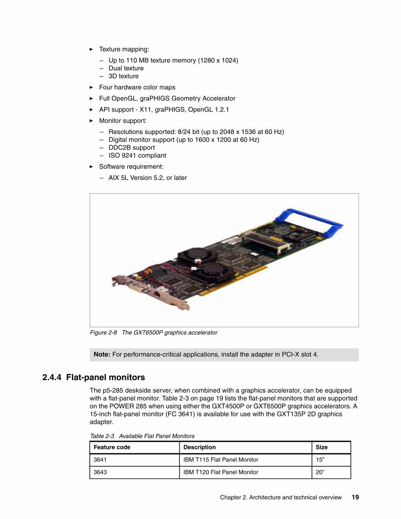
Figure 2-8 The GXT6500P graphics accelerator
2.4.4 Flat-panel monitorsThe p5-285 deskside server, when combined with a graphics accelerator, can be equipped with a flat-panel monitor. Table 2-3 on page 19 lists the flat-panel monitors that are supported on the POWER 285 when using either the GXT4500P or GXT6500P graphics accelerators. A 15-inch flat-panel monitor (FC 3641) is available for use with the GXT135P 2D graphics adapter.
Table 2-3 Available Flat Panel Monitors
Note: For performance-critical applications, install the adapter in PCI-X slot 4.
Feature code Description Size
3641 IBM T115 Flat Panel Monitor 15”
3643 IBM T120 Flat Panel Monitor 20”
Chapter 2. Architecture and technical overview 19

2.4.5 Audio adapterThe IntelliStation POWER 285 system supports a PCI audio adapter (FC 8244). It is a 3.3 volt, 32-bit PCI adapter that runs at 33 MHz and requires one, short 32-bit or 64-bit PCI-X slot. The adapter provides external jacks for headphones, speaker output, line input, microphone input, and an internal connector for CD or DVD drive audio input (Figure 2-9).
Figure 2-9 PCI audio adapter
2.4.6 SCSI adaptersTo connect to external SCSI devices, the orderable adapters provided in Table 2-4 are available, at the time of writing, to be used in the IntelliStation POWER 285 system.
Table 2-4 Orderable SCSI adapters
2.4.7 iSCSIiSCSI is an open, standards-based approach by which SCSI information is encapsulated using the TCP/IP protocol to allow its transport over IP networks, Internet SCSI. It allows
3644 IBM T119 Flat Panel Monitor 19”
3645 IBM T117 Flat Panel Monitor 17”
Feature code Description Size
Feature code
Description Slot Size Max
1907 Dual Channel SCSI Raid Enablement 64 Short 5
1912 PCI-X DDR Dual Channel Ultra320 LVD SCSI Adapter 64 Short 5
1913 PCI-X Dual Channel LVD SCSI RAID Adapter 64 Short 3
Note: There is also the option to make the internal Ultra320 SCSI channel externally accessible on the rear side of the system by installing FC 4275. No additional SCSI adapter is required in this case. No additional PCI-X slot is required.
20 IBM IntelliStation POWER 285 Technical Overview and Introduction

transfer of data between storage and servers in block I/O formats (defined by iSCSI protocol) and thus enables the creation of IP SANs. iSCSI allows an existing network to transfer SCSI commands and data with full location independence and defines the rules and processes to accomplish the communication. The iSCSI protocol is defined in iSCSI IETF draft-20. For more information about this standard, see:
http://tools.ietf.org/html/rfc3720
New iSCSI adapters for IBM System p5 systems provide the advantage of increased bandwidth through the hardware support of iSCSI protocol. The 1 Gigabit iSCSI TOE PCI-X adapters support hardware encapsulation of SCSI commands and data into TCP and transports over the Ethernet using IP packets. The adapter operates as an iSCSI TOE (TCP/IP Offload Engine). This offload function eliminates host protocol processing and reduces CPU interrupts. Adapter uses Small form factor LC type fiber optic connector or copper RJ45 connector. Table 2-5 provides the orderable iSCSI adapters.
Table 2-5 Available iSCSI adapters
IBM iSCSI software Host Support KitThe iSCSI protocol can also be used over standard Gigabit Ethernet adapters. To use this approach, download the appropriate iSCSI Host Support Kit for your operating system from the IBM NAS support Web site:
http://www.ibm.com/storage/support/nas/
The iSCSI Host Support Kit on AIX 5L and Linux® acts as a software iSCSI initiator and allows access to iSCSI target storage devices using standard Gigabit Ethernet network adapters. To ensure the best performance enable the TCP Large Send, TCP send and receive flow control, and Jumbo Frame features of the Gigabit Ethernet Adapter and the iSCSI Target, tune network options and interface parameters for maximum iSCSI I/O throughput on the operating system.
2.4.8 Fibre Channel adaptersThe IntelliStation POWER 285 supports direct or SAN connection to devices using Fibre Channel adapters. Single-port Fibre Channel adapters are available in 2-Gbps and 4-Gbps speeds. A dual-port 4-Gbps Fibre Channel adapter is also available. Table 2-6 on page 22 provides a summary of the available Fibre Channel adapters.
All of these adapters have LC connectors. If you are attaching a device or switch with an SC type fiber connector an LC-SC 50 Micron Fiber Converter Cable (FC 2456) or an LC-SC 62.5 Micron Fiber Converter Cable (FC 2459) is required.
Supported data rates between the server and the attached device or switch are as follows: Distances of up to 500 meters running at 1 Gbps, distances up to 300 meters running at 2 Gbps data rate, and distances up to 150 meters running at 4 Gbps. When these adapters are used with IBM supported Fibre Channel storage switches supporting long-wave optics, distances of up to 10 kilometers are capable running at either 1 Gbps, 2 Gbps, or 4 Gbps data rates.
Feature code Description Slot Size Max
1986 Gigabit iSCSI TOE PCI-X on copper media adapter 64 short 3
1987 Gigabit iSCSI TOE PCI-X on optical media adapter 64 short 3
Chapter 2. Architecture and technical overview 21
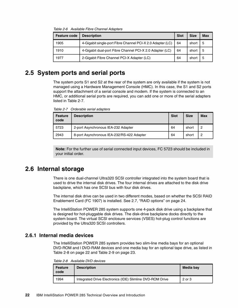
Table 2-6 Available Fibre Channel Adapters
2.5 System ports and serial portsThe system ports S1 and S2 at the rear of the system are only available if the system is not managed using a Hardware Management Console (HMC). In this case, the S1 and S2 ports support the attachment of a serial console and modem. If the system is connected to an HMC, or additional serial ports are required, you can add one or more of the serial adapters listed in Table 2-7.
Table 2-7 Orderable serial adapters
2.6 Internal storageThere is one dual-channel Ultra320 SCSI controller integrated into the system board that is used to drive the internal disk drives. The four internal drives are attached to the disk drive backplane, which has one SCSI bus with four disk drives.
The internal disk drive can be used in two different modes, based on whether the SCSI RAID Enablement Card (FC 1907) is installed. See 2.7, “RAID options” on page 24.
The IntelliStation POWER 285 system supports one 4-pack disk drive using a backplane that is designed for hot-pluggable disk drives. The disk-drive backplane docks directly to the system board. The virtual SCSI enclosure services (VSES) hot-plug control functions are provided by the Ultra320 SCSI controllers.
2.6.1 Internal media devicesThe IntelliStation POWER 285 system provides two slim-line media bays for an optional DVD-ROM and l DVD-RAM devices and one media bay for an optional tape drive, as listed in Table 2-8 on page 22 and Table 2-9 on page 23.
Table 2-8 Available DVD devices
Feature code Description Slot Size Max
1905 4-Gigabit single-port Fibre Channel PCI-X 2.0 Adapter (LC) 64 short 5
1910 4-Gigabit dual-port Fibre Channel PCI-X 2.0 Adapter (LC) 64 short 5
1977 2-Gigabit Fibre Channel PCI-X Adapter (LC) 64 short 5
Feature code
Description Slot Size Max
5723 2-port Asynchronous IEA-232 Adapter 64 short 2
2943 8-port Asynchronous IEA-232/RS-422 Adapter 64 short 2
Note: For the further use of serial connected input devices, FC 5723 should be included in your initial order.
Feature code
Description Media bay
1994 Integrated Drive Electronics (IDE) Slimline DVD-ROM Drive 2 or 3
22 IBM IntelliStation POWER 285 Technical Overview and Introduction
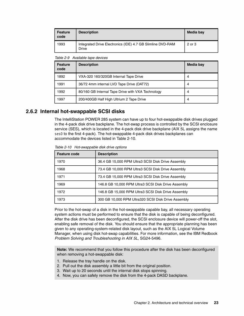
Table 2-9 Available tape devices
2.6.2 Internal hot-swappable SCSI disksThe IntelliStation POWER 285 system can have up to four hot-swappable disk drives plugged in the 4-pack disk drive backplane. The hot-swap process is controlled by the SCSI enclosure service (SES), which is located in the 4-pack disk drive backplane (AIX 5L assigns the name ses0 to the first 4-pack). The hot-swappable 4-pack disk drives backplanes can accommodate the devices listed in Table 2-10.
Table 2-10 Hot-swappable disk drive options
Prior to the hot-swap of a disk in the hot-swappable capable bay, all necessary operating system actions must be performed to ensure that the disk is capable of being deconfigured. After the disk drive has been deconfigured, the SCSI enclosure device will power-off the slot, enabling safe removal of the disk. You should ensure that the appropriate planning has been given to any operating-system-related disk layout, such as the AIX 5L Logical Volume Manager, when using disk hot-swap capabilities. For more information, see the IBM Redbook Problem Solving and Troubleshooting in AIX 5L, SG24-5496.
1993 Integrated Drive Electronics (IDE) 4.7 GB Slimline DVD-RAM Drive
2 or 3
Feature code
Description Media bay
1892 VXA-320 160/320GB Internal Tape Drive 4
1991 36/72 4mm internal LVD Tape Drive (DAT72) 4
1992 80/160 GB Internal Tape Drive with VXA Technology 4
1997 200/400GB Half High Ultrium 2 Tape Drive 4
Feature code
Description Media bay
Feature code Description
1970 36.4 GB 15,000 RPM Ultra3 SCSI Disk Drive Assembly
1968 73.4 GB 10,000 RPM Ultra3 SCSI Disk Drive Assembly
1971 73.4 GB 15,000 RPM Ultra3 SCSI Disk Drive Assembly
1969 146.8 GB 10,000 RPM Ultra3 SCSI Disk Drive Assembly
1972 146.8 GB 15,000 RPM Ultra3 SCSI Disk Drive Assembly
1973 300 GB 10,000 RPM Ultra320 SCSI Disk Drive Assembly
Note: We recommend that you follow this procedure after the disk has been deconfigured when removing a hot-swappable disk:
1. Release the tray handle on the disk.2. Pull out the disk assembly a little bit from the original position.3. Wait up to 20 seconds until the internal disk stops spinning.4. Now, you can safely remove the disk from the 4-pack DASD backplane.
Chapter 2. Architecture and technical overview 23
After the SCSI disk hot-swap procedure, you can expect to find SCSI_ERR10 logged in the AIX 5L error log, with the second word of the sense data equal to 0017. It is generated from a SCSI bus reset issued by the SES to reset all processes when a drive is inserted, and it is not an issue.
A disk lock feature (FC 6585) is also available to secure the disk drives so that they cannot be removed.
2.7 RAID optionsInternal hardware RAID is available on the IntelliStation POWER 285 system.
Install the Dual Channel SCSI RAID Enablement Card (FC 1907). Install four disk drives in the 4-pack DASD backplane (FC 6574). This enables RAID 0, 5, or 10 capabilities within a single 4-pack of DASD with one RAID controller.
2.8 Operating system requirementsAIX 5L has been specifically developed and enhanced to exploit and support the extensive RAS features on IBM System p5 servers. At the time of writing, IBM AIX 5L Version 5.2 and Version 5.3 is supported on the IntelliStation POWER 285 system with the following release requirements:
� 2.1 GHz POWER5+ processors:
– AIX 5L for POWER V5.3 with 5300-04 Technology Level (APAR IY77273), or later– AIX 5L for POWER V5.2 with 5200-08 Technology Level (APAR IY77270), or later
� 1.9 GHz POWER5+ processors:
– AIX 5L for POWER V5.3 with Maintenance Package 5300-03 (IY71011), or later– AIX 5L for POWER V5.2 with Maintenance Package 5200-07 (IY67914) or later
The increased capacity of DVD means fewer media to handle when installing from DVD media. If you want to receive the AIX 5L software on DVD media, order the DVD preference feature FC 3435.
IBM periodically releases maintenance packages for the AIX 5L operating system. These packages are available on CD-ROM (FC 0907), or they can be downloaded from the IBM Web site:
http://www.ibm.com/servers/eserver/support/
You can also get individual operating system fixes and information about obtaining AIX 5L service at this site. In AIX 5L Version 5.3, the suma command is also available to help the administrator automate the task of checking and downloading operating system downloads.
For more information about the suma command functionality, refer to:
http://www14.software.ibm.com/webapp/set2/sas/f/suma/home.html
If you have problems downloading the latest maintenance level, ask your IBM Business Partner or IBM representative for assistance.
24 IBM IntelliStation POWER 285 Technical Overview and Introduction

2.9 Service processorThe service processor is an embedded controller based on a PowerPC 405GP processor (PPC405) implementation running the service processor internal operating system. The service processor operating system contains specific programs and device drivers for the service processor hardware.
The key components include a flexible service processor-base (FSP-B) and an extender chipset (FSP-E). Figure 2-10 illustrates the service processor.
Figure 2-10 Service processor block diagram
The flexible service processor core is a five-stage pipeline instruction processor and contains 32-bit general purpose registers. The flash ROM contains a compressed image of a software load.
Service processorblock diagram
Base(FSP-B)
DS1-wire
Rack Ind Conn
Flash ROM40 MB or48 MB
SRAM 1 MB
NVRAM Controller
DDR Interface
FlashNVRAMInterface
UART #2
UART #1
UART #3
UART #4
BroadcomPHY
RJ-45
RJ-45 Enet #1
Enet # 2
ALE
DDR 64 MB
I2CEngines
4 I2C Engines
JTAGEngines
2 JTAGEngines
RTC32.768 KHzOSC
INTR8
Interrupts
PCI-X at 100 MHz
Extender(FSP-E)
UART #1-2, 7-9
I2CEngines 6 I2C EnginesJTAG
Engines 8 JTAG Engines
INTR 5 Interrupts
UART #3
UART #4
UART #3
UART #5, Port0
UART #6 To Smartchip VPD Serial MUX
GPIO
GPIO
HMCPorts
TOD/SIT4 MHzOSC
RISC WatchConn
Secondary PCI Secondary PCI
PCI Bus
MUXX/R X/R PS1
XCVRS2-rearDB9
XCVRS1-rearDB9
Chapter 2. Architecture and technical overview 25

26 IBM IntelliStation POWER 285 Technical Overview and Introduction

Chapter 3. RAS and manageability
This chapter provides information about IBM System p5 design features that help lower the total cost of ownership (TCO). IBM reliability, availability, and service (RAS) technology allow you to improve your TCO architecture by reducing unplanned down time.
This chapter provides more detailed information about the IBM IntelliStation POWER 285 system’s RAS features. It includes several features about the benefits available when using IBM AIX 5L.
3
© Copyright IBM Corp. 2005, 2006. All rights reserved. 27

3.1 Reliability, fault tolerance, and data integrityExcellent quality and reliability are inherent in all aspects of the IBM IntelliStation POWER 285 workstation processor design and manufacturing. The fundamental objective of the design approach is to minimize outages. The RAS features help to ensure that the system operates when required, performs reliably, and efficiently handles any failures that might occur. This is achieved using capabilities that are provided by both the hardware and the operating system AIX 5L.
The IntelliStation POWER 285 workstation as a POWER5+ server enhances the RAS capabilities that are implemented in POWER4-based systems. RAS enhancements available on POWER5 and POWER5+ servers are:
� Most firmware updates allow the system to remain operational.� The ECC has been extended to inter-chip connections for the fabric and processor bus.� Partial L2 cache deallocation is possible.� The number of L3 cache line deletes improved from two to ten for better self-healing
capability.
The following sections describe the concepts that form the basis of leadership RAS features of IBM IntelliStation POWER 285 workstation in more detail.
3.1.1 Fault avoidanceIBM IntelliStation POWER 285 workstations are built on a quality-based design that is intended to keep errors from happening. This design includes the following features:
� Reduced power consumption and cooler operating temperatures for increased reliability, which are enabled by the use of copper circuitry, silicon-on-insulator, and dynamic clock gating
� Mainframe-inspired components and technologies
3.1.2 First-failure data captureIf a problem should occur, the ability to diagnose that problem correctly is a fundamental requirement upon which improved availability is based. The IntelliStation POWER 285 incorporate advanced capability in start-up diagnostics and in run time First-failure data capture (FDDC) based on strategic error checkers built into the processors.
Any errors detected by the pervasive error checkers are captured into Fault Isolation Registers (FIRs), which can be interrogated by the service processor. The service processor has the capability to access system components using special purpose ports or by accessing error registers. Figure 3-1 on page 29 shows a schematic of a Fault Register Implementation.
28 IBM IntelliStation POWER 285 Technical Overview and Introduction
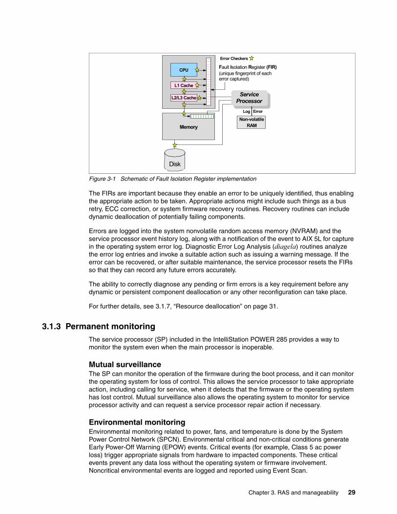
Figure 3-1 Schematic of Fault Isolation Register implementation
The FIRs are important because they enable an error to be uniquely identified, thus enabling the appropriate action to be taken. Appropriate actions might include such things as a bus retry, ECC correction, or system firmware recovery routines. Recovery routines can include dynamic deallocation of potentially failing components.
Errors are logged into the system nonvolatile random access memory (NVRAM) and the service processor event history log, along with a notification of the event to AIX 5L for capture in the operating system error log. Diagnostic Error Log Analysis (diagela) routines analyze the error log entries and invoke a suitable action such as issuing a warning message. If the error can be recovered, or after suitable maintenance, the service processor resets the FIRs so that they can record any future errors accurately.
The ability to correctly diagnose any pending or firm errors is a key requirement before any dynamic or persistent component deallocation or any other reconfiguration can take place.
For further details, see 3.1.7, “Resource deallocation” on page 31.
3.1.3 Permanent monitoringThe service processor (SP) included in the IntelliStation POWER 285 provides a way to monitor the system even when the main processor is inoperable.
Mutual surveillanceThe SP can monitor the operation of the firmware during the boot process, and it can monitor the operating system for loss of control. This allows the service processor to take appropriate action, including calling for service, when it detects that the firmware or the operating system has lost control. Mutual surveillance also allows the operating system to monitor for service processor activity and can request a service processor repair action if necessary.
Environmental monitoringEnvironmental monitoring related to power, fans, and temperature is done by the System Power Control Network (SPCN). Environmental critical and non-critical conditions generate Early Power-Off Warning (EPOW) events. Critical events (for example, Class 5 ac power loss) trigger appropriate signals from hardware to impacted components. These critical events prevent any data loss without the operating system or firmware involvement. Noncritical environmental events are logged and reported using Event Scan.
CPU
L1 Cache
L2/L3 Cache
Memory
Fault Isolation Register (FIR)(unique fingerprint of each error captured)
ServiceProcessor
Non-volatileRAM
Error Checkers
Log Error
Disk
Chapter 3. RAS and manageability 29

The operating system cannot program or access the temperature threshold using the SP. EPOW events can, for example, trigger the following actions.
� Temperature monitoring, which increases the fans’ speed rotation when ambient temperature is above a preset operating range.
� Temperature monitoring warns the system administrator of potential environmental-related problems. It also performs an orderly system shutdown when the operating temperature exceeds a critical level.
� Voltage monitoring provides warning and an orderly system shutdown when the voltage is out of the operational specification.
3.1.4 Self-healingFor a system to be self-healing, it must be able to recover from a failing component by first detecting and isolating the failed component, taking it offline, fixing or isolating it, and reintroducing the fixed or replacement component into service without any application disruption. Examples include:
� Bit steering to redundant memory in the event of a failed memory chip to keep the server operational
� Bit-scattering, thus allowing for error correction and continued operation in the presence of a complete chip failure (Chipkill™ recovery)
� Single-bit error-correction using ECC without reaching error thresholds for main, L2, and L3 cache memory
� L3 cache line deletes extended from 2 to 10 for additional self-healing
� ECC extended to inter-chip connections on fabric and processor bus
� Memory scrubbing to help prevent soft-error memory faults
Memory reliability, fault tolerance, and integrityThe IntelliStation POWER 285 use Error Checking and Correcting (ECC) circuitry for system memory to correct single-bit and to detect double-bit memory failures. Detection of double-bit memory failures helps maintain data integrity. Furthermore, the memory chips are organized such that the failure of any specific memory chip only affects a single bit within a four-bit ECC word (bit-scattering), thus allowing for error correction and continued operation in the presence of a complete chip failure (Chipkill recovery). The memory DIMMs also use memory scrubbing and thresholding to determine when spare memory chips within each bank of memory should be used to replace ones that have exceeded their threshold of error count (dynamic bit-steering). Memory scrubbing is the process of reading the contents of the memory during idle time and checking and correcting any single-bit errors that have accumulated by passing the data through the ECC logic. This function is a hardware function on the memory controller and does not influence normal system memory performance.
30 IBM IntelliStation POWER 285 Technical Overview and Introduction

3.1.5 N+1 redundancyThe use of redundant parts allows the IntelliStation POWER 285 to remain operational with full resources:
� Redundant spare memory bits in L1, L2, L3, and main memory� Redundant fans� Redundant power supplies (optional)
3.1.6 Fault maskingIf these corrections and retries succeed and do not exceed threshold limits, the system remains operational with full resources, and no intervention is required:
� CEC bus retry and recovery� PCI-X bus recovery� ECC Chipkill soft error
3.1.7 Resource deallocationIf recoverable errors exceed threshold limits, resources can be deallocated with the system remaining operational, allowing deferred maintenance at a convenient time.
Dynamic or persistent deallocation Dynamic deallocation of potentially failing components is nondisruptive, allowing the system to continue to run. Persistent deallocation occurs when a failed component is detected, which is then deactivated at a subsequent reboot.
Dynamic deallocation functions include:
� Processor� L3 cache line delete� Partial L2 cache deallocation� PCI-X bus and slots
For dynamic processor deallocation, the service processor performs a predictive failure analysis based on any recoverable processor errors that have been recorded. If these transient errors exceed a defined threshold, the event is logged and the processor is deallocated from the system while the operating system continues to run. This feature (named CPU Guard) enables maintenance to be deferred until a suitable time. Processor deallocation can only occur if there are sufficient functional processors (at least two).
To verify whether CPU Guard has been enabled, run the following command:
lsattr -El sys0 | grep cpuguard
If enabled, the output will be similar to the following:
cpuguard enable CPU Guard True
If the output shows CPU Guard as disabled, enter the following command to enable it:
chdev -l sys0 -a cpuguard='enable'
Note: With this optional feature every IntelliStation POWER 285, requires two power cords, which are not included in the base order. For maximum availability it is highly recommended to connect power cords from same IntelliStation POWER 285 to two independent power source in order to achieve maximum availability.
Chapter 3. RAS and manageability 31

Cache or cache-line deallocation is aimed at performing dynamic reconfiguration to bypass potentially failing components. This capability is provided for both L2 and L3 caches. Dynamic run-time deconfiguration is provided if a threshold of L1 or L2 recovered errors is exceeded.
In the case of an L3 cache run-time array single-bit solid error, the spare resources are used to perform a line delete on the failing line.
PCI hot-plug slot fault tracking helps prevent slot errors from causing a system machine check interrupt and subsequent reboot. This provides superior fault isolation, and the error affects only the single adapter. Run-time errors on the PCI bus caused by failing adapters will result in recovery action. If this is unsuccessful, the PCI device is shut down gracefully. Parity errors on the PCI bus itself result in bus retry, and if uncorrected, the bus and any I/O adapters or devices on that bus are deconfigured.
The IntelliStation POWER 285 supports PCI Extended Error Handling (EEH) if it is supported by the PCI-X adapter. In the past, PCI bus parity errors caused a global machine check interrupt, which eventually required a system reboot in order to continue. In the IntelliStation POWER 285 hardware, system firmware, and AIX 5L interaction have been designed to allow transparent recovery of intermittent PCI bus parity errors and graceful transition to the I/O device available state in the case of a permanent parity error in the PCI bus.
EEH-enabled adapters respond to a special data packet generated from the affected PCI slot hardware by calling system firmware, which examines the affected bus, allows the device driver to reset it, and continues without a system reboot.
Persistent deallocation functions include:
� Processor� Memory� Deconfigure or bypass failing I/O adapters� L3 cache
Following a hardware error that has been flagged by the service processor, the subsequent reboot of the system invokes extended diagnostics. If a processor or L3 cache is marked for deconfiguration by persistent processor deallocation, the boot process attempts to proceed to completion with the faulty device deconfigured automatically. Failing I/O adapters are deconfigured or bypassed during the boot process.
3.1.8 ServiceabilityIncreasing service productivity means the system is up and running for a longer time. The IntelliStation POWER 285 workstation improve service productivity by providing the functions described in the following sections.
Error indication and LED indicatorsThe IBM IntelliStation POWER 285 workstations are designed for client setup of the machine and for the subsequent addition of most hardware features. The IntelliStation POWER 285 also allow clients to replace service parts (Client Replaceable Unit). To accomplish this, the IntelliStation POWER 285 provide internal LED diagnostics that identify parts requiring
Note: The auto-restart (reboot) option, when enabled, can reboot the system automatically following an unrecoverable software error, software hang, hardware failure, or environmentally induced failure (such as loss of power supply).
32 IBM IntelliStation POWER 285 Technical Overview and Introduction

service. Attenuation of the error is provided through a series of light attention signals, starting on the exterior of the system (System Attention LED) located on the front of the system, and ending with an LED near the failing Field Replaceable Unit.
For more information about Client Replaceable Units, including videos, see:
http://publib.boulder.ibm.com/infocenter/eserver/v1r3s/index.jsp
System attention LEDThe attention indicator is represented externally by an amber LED on the operator panel and the back of the system unit. It is used to indicate that the system is in one of the following states:
� Normal state, LED is off. � Fault state, LED is on solid.� Identify state, LED is blinking.
Additional LEDs on I/O components such as PCI-X slots and disk drives provide status information such as power, hot-swap, and need for service.
Concurrent maintenanceConcurrent Maintenance provides replacement of the following parts while the system remains running:
� Disk drives� Cooling fans� Power subsystems� PCI-X adapter cards
3.2 ManageabilityThe functions and tools provided for IBM IntelliStation POWER 285 workstations to ease management are described in the next sections.
3.2.1 Service processorThe service processor (SP) is always working. CEC can be in the following states:
� Power standby mode (power off)� Operating, ready to start partitions� Operating with some partitions running and an AIX 5L or Linux system in control of the
system.
The SP is still working and checking the system for errors, ensuring the connection to the HMC (if present) for manageability purposes and accepting Advanced System Management Interface (ASMI) SSL network connections. The SP provides the possibility to view and manage the machine-wide settings using the ASMI and allows complete system and partition management from HMC. Also, the surveillance function of the SP is monitoring the operating system to check that it is still running and has not stalled.
Note: The IBM IntelliStation POWER 285 workstation service processor enables the analysis of a system that will not boot. It can be performed from either the ASMI, HMC, or ASCI console (depending on presence of HMC). ASMI is provided in any case.
Chapter 3. RAS and manageability 33

Figure 3-2 shows an example of the ASMI accessed from a Web browser.
Figure 3-2 Advanced System Management main menu
3.2.2 Service AgentService Agent is an application program that operates on an IBM IntelliStation POWER 285 workstation and monitors it for hardware errors. Service Agent reports detected errors, assuming they meet certain criteria for severity, to IBM for service with no intervention. It is an enhanced version of Service Director™ with a graphical user interface (GUI).
Key tasks you can accomplish using Service Agent for the IBM IntelliStation POWER 285 workstation, IBM System p5, pSeries, and RS/6000 include:
� Automatic VPD collection� Automatic problem analysis� Problem-definable threshold levels for error reporting� Automatic problem reporting where service calls placed to IBM without intervention� Automatic client notification
In addition:
� Commonly viewed hardware errors
You can view hardware event logs for any monitored machine in the network from any Service Agent host user interface.
� High-availability cluster multiprocessing (HACMP™) support for full fallback
34 IBM IntelliStation POWER 285 Technical Overview and Introduction
� Network environment support with minimum telephone lines for modems
� Communication base for performance data collection and reporting tool Performance Management (PM/AIX)
For more information about PM/AIX, see:
http://www.ibm.com/servers/aix/pmaix.html
Machines are defined by using the Service Agent user interface. After the machines are defined, they are registered with the IBM Service Agent Server (SAS). During the registration process, an electronic key is created that becomes part of your resident Service Agent program. This key is used each time the Service Agent places a call for service. The IBM Service Agent Server checks the current client service status from the IBM entitlement database. An email is returned to the client server requesting proper registration. If this reveals that you are not on Warranty or MA, the service call is refused and posted back using an e-mail notification.
Service agent can be configured to connect to IBM either using modem or network connection. In any case, the communication is encrypted and strong authentication is used. Service Agent only sends outbound transmissions and does not allow any inbound connection attempts. Only hardware machine configuration, machine status or error information is transmitted. Service Agent does not access or transmit any other data on the monitored systems.
Thee principal ways of communication are possible:
� Dial-up using attached modem device (uses the AT&T Global Network dialer for modem access, does not accept incoming calls to modem)
� VPN (IPsec is used in this case)
� HTTPS (can be configured to work with firewalls and authenticating proxies)
Additional services provided by Service Agent are:
� My Systems: Client and IBM persons authorized by the client can view hardware and software information and error messages that are gathered by Service Agent on Electronic Services WWW pages:
http://www.ibm.com/support/electronic
� Premium Search: Search service using information gathered by Service Agents (paid service that requires special contract).
� Performance Management: Service Agent provides means for collecting long term performance data. The data are collected in reports accessed by client on WWW pages of Electronic Services (paid service that requires special contract).
You can download the latest version of Service Agent at this IBM Web site:
ftp://ftp.software.ibm.com/aix/service_agent_code
Chapter 3. RAS and manageability 35
3.2.3 IBM IntelliStation POWER 285 firmware maintenanceThe IBM IntelliStation POWER 285 workstation, IBM system p5, pSeries and IBM RS/6000 customer-managed microcode is a methodology that enables you to manage and install microcode updates on systems and associated I/O adapters. For more information, see the IBM microcode update Web site:
http://www14.software.ibm.com/webapp/set2/firmware/gjsn
IBM provides service tools that can assist you in determining microcode levels and updating systems with the latest available microcode. To determine which tool to use in a specific environment, visit:
http://techsupport.services.ibm.com/server/mdownload/mcodetools.html
36 IBM IntelliStation POWER 285 Technical Overview and Introduction

Chapter 4. Workstation hints and tips
This chapter contains an introduction to CATIA and several administration aids related to the IBM IntelliStation POWER 285 workstation. Test and modify the scripts before placing them into production. We provide these scripts to give you an idea of the types of customization possible.
4
© Copyright IBM Corp. 2005, 2006. All rights reserved. 37
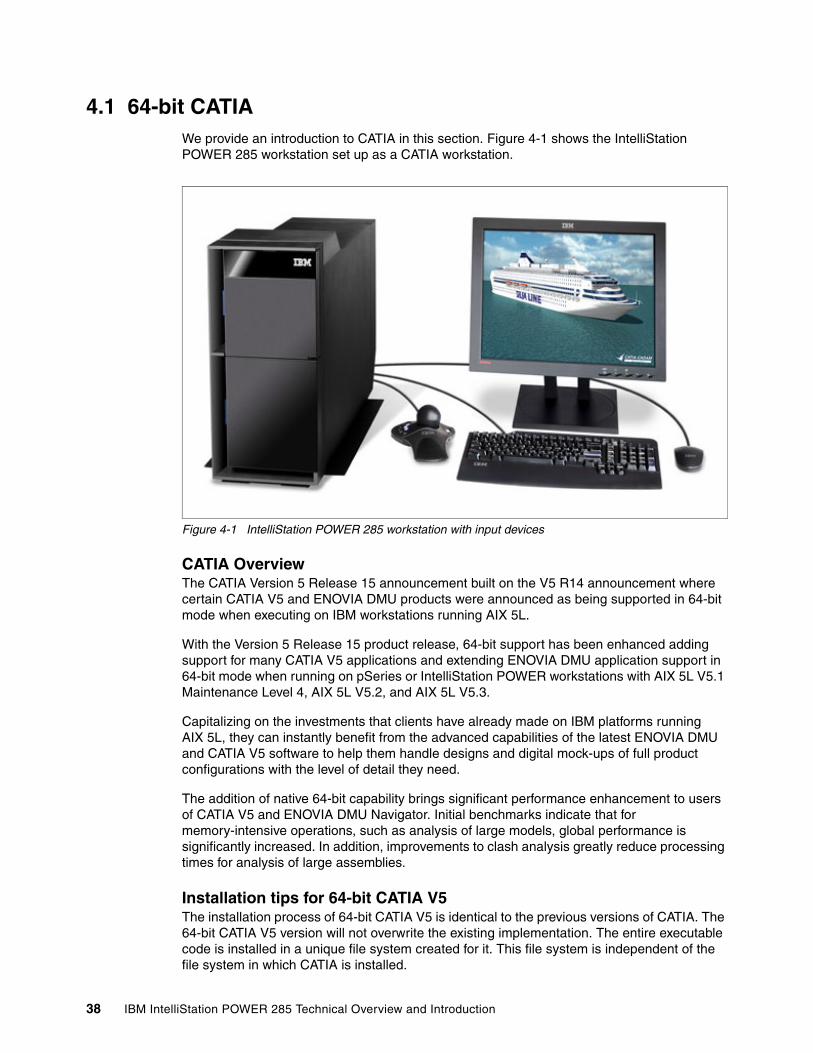
4.1 64-bit CATIA We provide an introduction to CATIA in this section. Figure 4-1 shows the IntelliStation POWER 285 workstation set up as a CATIA workstation.
Figure 4-1 IntelliStation POWER 285 workstation with input devices
CATIA OverviewThe CATIA Version 5 Release 15 announcement built on the V5 R14 announcement where certain CATIA V5 and ENOVIA DMU products were announced as being supported in 64-bit mode when executing on IBM workstations running AIX 5L.
With the Version 5 Release 15 product release, 64-bit support has been enhanced adding support for many CATIA V5 applications and extending ENOVIA DMU application support in 64-bit mode when running on pSeries or IntelliStation POWER workstations with AIX 5L V5.1 Maintenance Level 4, AIX 5L V5.2, and AIX 5L V5.3.
Capitalizing on the investments that clients have already made on IBM platforms running AIX 5L, they can instantly benefit from the advanced capabilities of the latest ENOVIA DMU and CATIA V5 software to help them handle designs and digital mock-ups of full product configurations with the level of detail they need.
The addition of native 64-bit capability brings significant performance enhancement to users of CATIA V5 and ENOVIA DMU Navigator. Initial benchmarks indicate that for memory-intensive operations, such as analysis of large models, global performance is significantly increased. In addition, improvements to clash analysis greatly reduce processing times for analysis of large assemblies.
Installation tips for 64-bit CATIA V5 The installation process of 64-bit CATIA V5 is identical to the previous versions of CATIA. The 64-bit CATIA V5 version will not overwrite the existing implementation. The entire executable code is installed in a unique file system created for it. This file system is independent of the file system in which CATIA is installed.
38 IBM IntelliStation POWER 285 Technical Overview and Introduction

Near the end of the installation process, a configuration window opens, requesting you to enter the current CATIA configuration environment location. Specify the environment path. The installation process is finished and you are ready to execute CATIA V5 64-bit. To have the complete CATIA V5 64-bit function, the AIX 5L kernel should be also on 64-bit. In the following sections, you can check the current AIX 5L environment and also change it to 64-bit.
4.1.1 Checking the AIX 5L kernel modeTo take the most advantage of the 64-bit support, install the 64-bit kernel (fileset bos.mp64). To ensure that the 64-bit kernel is running as expected, follow these steps:
1. Log in as the root user.2. Enter the bootinfo -K command.
If the kernel is running in 64-bit mode, the output of this command is 64.
4.1.2 Changing from a 32-bit to a 64-bit kernelIf the system is not running the 64-bit kernel, perform the following steps:
1. Log in as the root user.2. Enter the cd / command.3. Enter the ln -fs /usr/lib/boot/unix_64 unix command.4. Enter the cd /usr/lib/boot command.5. Enter the ln -fs /usr/lib/boot/unix_64 unix command.6. Enter the bosboot -ad /dev/ipldevice command.7. Enter the sync;sync;sync commands.8. Enter the shutdown -Fr command to reboot the 64-bit kernel.
4.2 Checking and changing the SMT settingThe smtctl command controls the enabling and disabling of processor simultaneous multithreading (SMT) mode.
The syntax is as follows:
smtctl [ -m off | on [ -w boot | now ]]
This command is provided for privileged users and applications to control the use of processors with simultaneous multithreading support. The simultaneous multithreading mode allows processors to have thread-level parallelism at the instruction level. This mode can be enabled or disabled for all processors either immediately or on subsequent boots of the system. This command controls the simultaneous multithreading options.
The following flags are supported:
-m off This option sets simultaneous multithreading mode to disabled.
-m on This option sets simultaneous multithreading mode to enabled.
-w boot This option makes the simultaneous multithreading mode change effective on the next and subsequent reboots if you run the bosboot command before the next system reboot.
Note: The 64-bit CATIA V5 will run without an error message even when AIX 5L is running the 32-bit kernel.
Chapter 4. Workstation hints and tips 39

-w now This option makes the simultaneous multithreading mode change immediately but will not persist across a reboot. If neither the -w boot nor the -w now options are specified, the mode change is made immediately. It will persist across subsequent reboots if you run the bosboot command before the next system reboot.
If no options are specified, the following simultaneous multithreading settings will be reported:
SMT Capability Indicator that the physical or virtual processors are capable of simultaneous multithreading.
SMT Mode Current run time simultaneous multithreading mode of disabled or enabled.
SMT Boot Mode Current boot time simultaneous multithreading mode of disabled or enabled.
SMT Threads Number of simultaneous multithreading threads per physical or virtual processor.
SMT Bound Indicator that the simultaneous multithreading threads are bound on the same physical or virtual processor.
To enable simultaneous multithreading for the current boot cycle, enter:
smtctl -m on -w now
The system displays a message similar to the following message:
smtctl: SMT is now enabled.
To view the current simultaneous multithreading mode settings and processor information, enter this command:
smtctl
The system displays a message similar to the message in Example 4-1.
Example 4-1 Output from smtctl command
This system is SMT capable.
SMT is currently enabled.
SMT boot mode is set to disabled.
proc0 has 2 SMT threadsBind processor 0 is bound with proc0Bind processor 1 is bound with proc0
proc2 has 2 SMT threadsBind processor 2 is bound with proc2Bind processor 3 is bound with proc2
To disable simultaneous multithreading for the current boot cycle and for all subsequent boots, enter:
smtctl -m off
40 IBM IntelliStation POWER 285 Technical Overview and Introduction

The system displays a message similar to the following message:
smtctl: SMT is now disabled. It will persist across reboots if you run the bosboot command before the next reboot.
4.3 Network Installation ManagementNetwork Installation Management (NIM) is an excellent feature of the AIX 5L operating system and is important for teams or companies that have a need to install or upgrade many systems with the same images at the same time.
Some of the benefits of NIM are:
� Manageability: NIM enables central localization of software installation images, thus making backup and administration easier.
� Central administration: Administrators can install remote AIX 5L machines without having to physically attend them.
� Scalability: You can install more than one machine at a time, implement a group strategy of machines and resources, and choose how many machines to install at a time.
� Non-prompted installation: NIM provides a function to install systems without having to go to the machine, thus avoiding the manual machine-by-machine method.
� Convenient installations: Installations can be initiated by either the client or master at a convenient time. For example, if a client is unavailable at the time of the installation, you can initiate an installation when it is back online, or if there is less traffic on your network at a certain time, you can initiate the installations to occur then.
In previous versions of AIX 5L, NIM used the rsh and rcmd commands to perform the remote execution of commands on clients. These r- commands were a potential security exposure when running on an untrusted network.
AIX 5L Version 5.3 is enhanced by the nimsh environment that is part of the bos.sysmgt.nim.client fileset. It enables the following two remote execution environments:
� NIM service handler for client communication: Basic nimsh� NIM cryptographic authentication: OpenSSL
While the basic nimsh is an easy-to-use solution with sufficient security, OpenSSL provides additional up-to-date cryptographic security.
The original rsh or rcmd command environments are still supported in Version 5.3 because of compatibility and ease-of-use reasons.
NIM scriptsTo manage many machines, NIM scripting is helpful for administrators to establish a NIM-based inventory environment. Example 4-2 on page 42 provides a sample script for a specific client to examine the machine topology and store the result in HTML format.
Note: The boot image must be remade with the bosboot command before the next reboot.
Chapter 4. Workstation hints and tips 41
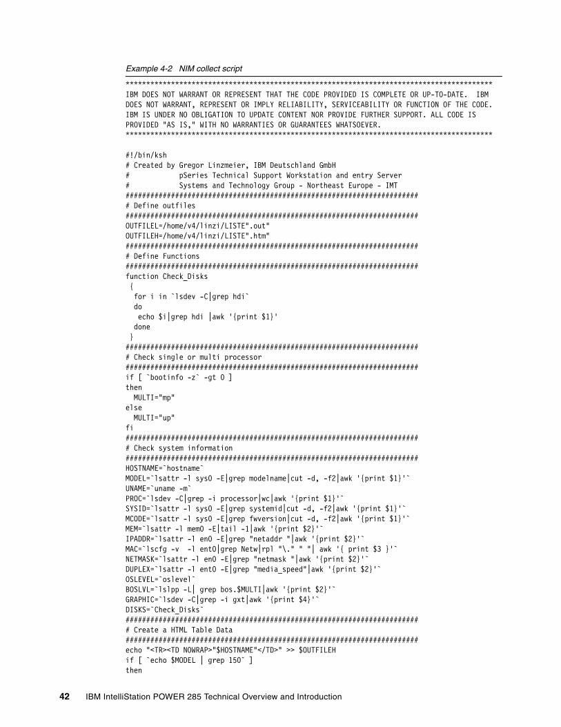
Example 4-2 NIM collect script
*****************************************************************************************IBM DOES NOT WARRANT OR REPRESENT THAT THE CODE PROVIDED IS COMPLETE OR UP-TO-DATE. IBM DOES NOT WARRANT, REPRESENT OR IMPLY RELIABILITY, SERVICEABILITY OR FUNCTION OF THE CODE. IBM IS UNDER NO OBLIGATION TO UPDATE CONTENT NOR PROVIDE FURTHER SUPPORT. ALL CODE IS PROVIDED "AS IS," WITH NO WARRANTIES OR GUARANTEES WHATSOEVER. *****************************************************************************************
#!/bin/ksh# Created by Gregor Linzmeier, IBM Deutschland GmbH# pSeries Technical Support Workstation and entry Server# Systems and Technology Group - Northeast Europe - IMT######################################################################## Define outfiles#######################################################################OUTFILEL=/home/v4/linzi/LISTE".out"OUTFILEH=/home/v4/linzi/LISTE".htm"######################################################################## Define Functions#######################################################################function Check_Disks { for i in `lsdev -C|grep hdi` do echo $i|grep hdi |awk '{print $1}' done }######################################################################## Check single or multi processor#######################################################################if [ `bootinfo -z` -gt 0 ]then MULTI="mp"else MULTI="up"fi######################################################################## Check system information#######################################################################HOSTNAME=`hostname`MODEL=`lsattr -l sys0 -E|grep modelname|cut -d, -f2|awk '{print $1}'`UNAME=`uname -m`PROC=`lsdev -C|grep -i processor|wc|awk '{print $1}'`SYSID=`lsattr -l sys0 -E|grep systemid|cut -d, -f2|awk '{print $1}'`MCODE=`lsattr -l sys0 -E|grep fwversion|cut -d, -f2|awk '{print $1}'`MEM=`lsattr -l mem0 -E|tail -1|awk '{print $2}'`IPADDR=`lsattr -l en0 -E|grep "netaddr "|awk '{print $2}'`MAC=`lscfg -v -l ent0|grep Netw|rpl "\." " "| awk '{ print $3 }'`NETMASK=`lsattr -l en0 -E|grep "netmask "|awk '{print $2}'`DUPLEX=`lsattr -l ent0 -E|grep "media_speed"|awk '{print $2}'`OSLEVEL=`oslevel`BOSLVL=`lslpp -L| grep bos.$MULTI|awk '{print $2}'`GRAPHIC=`lsdev -C|grep -i gxt|awk '{print $4}'`DISKS=`Check_Disks`######################################################################## Create a HTML Table Data#######################################################################echo "<TR><TD NOWRAP>"$HOSTNAME"</TD>" >> $OUTFILEHif [ `echo $MODEL | grep 150` ]then
42 IBM IntelliStation POWER 285 Technical Overview and Introduction
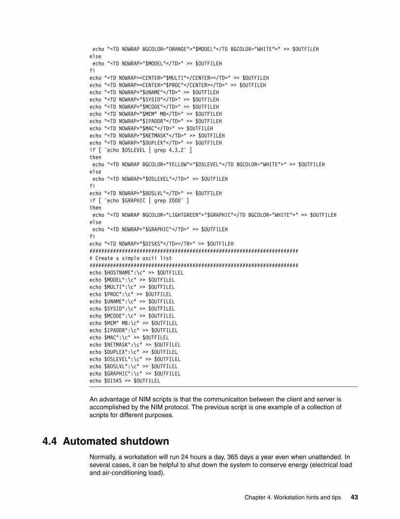
echo "<TD NOWRAP BGCOLOR="ORANGE">"$MODEL"</TD BGCOLOR="WHITE">" >> $OUTFILEHelse echo "<TD NOWRAP>"$MODEL"</TD>" >> $OUTFILEHfiecho "<TD NOWRAP><CENTER>"$MULTI"</CENTER></TD>" >> $OUTFILEHecho "<TD NOWRAP><CENTER>"$PROC"</CENTER></TD>" >> $OUTFILEHecho "<TD NOWRAP>"$UNAME"</TD>" >> $OUTFILEHecho "<TD NOWRAP>"$SYSID"</TD>" >> $OUTFILEHecho "<TD NOWRAP>"$MCODE"</TD>" >> $OUTFILEHecho "<TD NOWRAP>"$MEM" MB</TD>" >> $OUTFILEHecho "<TD NOWRAP>"$IPADDR"</TD>" >> $OUTFILEHecho "<TD NOWRAP>"$MAC"</TD>" >> $OUTFILEHecho "<TD NOWRAP>"$NETMASK"</TD>" >> $OUTFILEHecho "<TD NOWRAP>"$DUPLEX"</TD>" >> $OUTFILEHif [ `echo $OSLEVEL | grep 4.3.2` ]then echo "<TD NOWRAP BGCOLOR="YELLOW">"$OSLEVEL"</TD BGCOLOR="WHITE">" >> $OUTFILEHelse echo "<TD NOWRAP>"$OSLEVEL"</TD>" >> $OUTFILEHfiecho "<TD NOWRAP>"$BOSLVL"</TD>" >> $OUTFILEHif [ `echo $GRAPHIC | grep 2000` ]then echo "<TD NOWRAP BGCOLOR="LIGHTGREEN">"$GRAPHIC"</TD BGCOLOR="WHITE">" >> $OUTFILEHelse echo "<TD NOWRAP>"$GRAPHIC"</TD>" >> $OUTFILEHfiecho "<TD NOWRAP>"$DISKS"</TD></TR>" >> $OUTFILEH######################################################################## Create a simple ascii list#######################################################################echo $HOSTNAME":\c" >> $OUTFILELecho $MODEL":\c" >> $OUTFILELecho $MULTI":\c" >> $OUTFILELecho $PROC":\c" >> $OUTFILELecho $UNAME":\c" >> $OUTFILELecho $SYSID":\c" >> $OUTFILELecho $MCODE":\c" >> $OUTFILELecho $MEM" MB:\c" >> $OUTFILELecho $IPADDR":\c" >> $OUTFILELecho $MAC":\c" >> $OUTFILELecho $NETMASK":\c" >> $OUTFILELecho $DUPLEX":\c" >> $OUTFILELecho $OSLEVEL":\c" >> $OUTFILELecho $BOSLVL":\c" >> $OUTFILELecho $GRAPHIC":\c" >> $OUTFILELecho $DISKS >> $OUTFILEL
An advantage of NIM scripts is that the communication between the client and server is accomplished by the NIM protocol. The previous script is one example of a collection of scripts for different purposes.
4.4 Automated shutdownNormally, a workstation will run 24 hours a day, 365 days a year even when unattended. In several cases, it can be helpful to shut down the system to conserve energy (electrical load and air-conditioning load).
Chapter 4. Workstation hints and tips 43
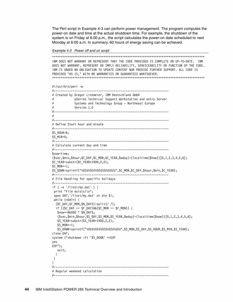
The Perl script in Example 4-3 can perform power management. The program computes the power-on date and time at the actual shutdown time. For example, the shutdown of the system is on Friday at 6:00 p.m,. the script calculates the power-on date scheduled to next Monday at 6:00 a.m. In summary, 60 hours of energy saving can be achieved.
Example 4-3 Power off and on script
*****************************************************************************************IBM DOES NOT WARRANT OR REPRESENT THAT THE CODE PROVIDED IS COMPLETE OR UP-TO-DATE. IBM DOES NOT WARRANT, REPRESENT OR IMPLY RELIABILITY, SERVICEABILITY OR FUNCTION OF THE CODE. IBM IS UNDER NO OBLIGATION TO UPDATE CONTENT NOR PROVIDE FURTHER SUPPORT. ALL CODE IS PROVIDED "AS IS," WITH NO WARRANTIES OR GUARANTEES WHATSOEVER. *****************************************************************************************
#!/usr/bin/perl -w#-------------------------------------------------------------------# Created by Gregor Linzmeier, IBM Deutschland GmbH# pSeries Technical Support Workstation and entry Server# Systems and Technology Group - Northeast Europe# Version 1.0#-------------------------------------------------------------------##------------------------------------------------------------------- # Define Start hour and minute#-------------------------------------------------------------------$S_HOUR=6;$S_MIN=0;#-------------------------------------------------------------------# Calculate current day and time#-------------------------------------------------------------------$now=time;($sec,$min,$hour,$C_DAY,$C_MON,$C_YEAR,$wday)=(localtime($now))[0,1,2,3,4,5,6];$C_YEAR=substr($C_YEAR+1900,2,2);$C_MON+=1;$S_DOWN=sprintf("%02d%02d%02d%02d%02d",$C_MON,$C_DAY,$hour,$min,$C_YEAR);#-------------------------------------------------------------------# File Handling for specific holidays#-------------------------------------------------------------------if ( -e '/linzi/my.dat' ) { print "File exists!\n"; open DAT,'/linzi/my.dat' or die $!; while (<DAT>) { ($F_DAY,$F_MON,$N_DAYS)=split(/ /); if (($C_DAY == $F_DAY)&&($C_MON == $F_MON)) { $now+=86400 * $N_DAYS; ($sec,$min,$hour,$S_DAY,$S_MON,$S_YEAR,$wday)=(localtime($now))[0,1,2,3,4,5,6]; $S_YEAR=substr($S_YEAR+1900,2,2); $S_MON+=1; $S_DOWN=sprintf("%02d%02d%02d%02d%02d",$S_MON,$S_DAY,$S_HOUR,$S_MIN,$S_YEAR);close DAT;system ("shutdown -Ft '$S_DOWN' <<EOFyesEOF"); exit; } }}#-------------------------------------------------------------------# Regular weekend calculation#-------------------------------------------------------------------
44 IBM IntelliStation POWER 285 Technical Overview and Introduction

print "File does'nt exists or Regular calculation\n";$now+=172800;($sec,$min,$hour,$S_DAY,$S_MON,$S_YEAR,$wday)=(localtime($now))[0,1,2,3,4,5,6];$S_YEAR=substr($S_YEAR+1900,2,2);$S_MON+=1;$S_DOWN=sprintf("%02d%02d%02d%02d%02d",$S_MON,$S_DAY,$S_HOUR,$S_MIN,$S_YEAR);system ("shutdown -Ft '$S_DOWN' <<EOFyesEOF");#-------------------------------------------------------------------
To cover national holidays or holiday seasons, the file in Example 4-4 can be enhanced with individual dates to keep the system in a power-off state. For each line, use the following format: start-day, month, year, number of power-off days. If the file is out of date, the program will still maintain the regular weekend power off.
Example 4-4 Power off calendar
1 1 2005 37 2 2005 528 5 2005 413 8 2005 3
Implement the entire mechanism through the AIX 5L crontab file. Example 4-5 shows the additional entry in root’s crontab to execute the Perl script on every Friday at 6:00 p.m.
Example 4-5 Crontab entry for power off and on
# Crontab entry for automatic power off0 18 * * 5 /usr/local/script/poffpon.pl
4.5 Wake on LANIntroduced with the POWER5 technology, the flexible service processor (FSP) provides an additional functionality to the IntelliStation POWER 285 system. In some situations, it is very helpful to power on a system without physically pushing the white button on the operator control panel.
Wake on LAN® is implemented only on the integrated Gigabit Ethernet and interfaced to the FSP. The Ethernet controller supports both Advanced Power Management™ (APM) wake up and Advanced Configuration and Power Interface (ACPI) wake up. The APM wake up uses the APM_WAKEUP signal to wake up the system.
Before using the Wake on LAN, it must be activated on the FSP using the ASMI interface. See 3.2.1, “Service processor” on page 33 for further information.
Note: To execute a Perl script, check if the perl.rte fileset is installed.
Note: Beginning with AIX 5L V5.2 ML4, the wol command is integrated in the AIX 5L operating system.
Chapter 4. Workstation hints and tips 45
4.6 AIX Toolbox for LinuxThe AIX 5L platform is the premier operating system from IBM for IBM System p5 and eServer pSeries systems. In order to enhance interoperability between Linux and AIX 5L, IBM has ported a collection of open source software (OSS) tools and bundled them into a toolbox for users of AIX 5L: The AIX Toolbox for Linux Applications. Figure 4-2 shows the media.
Figure 4-2 AIX Toolbox media
The Toolbox contains a collection of open source software that works with both AIX Version 4.3.3 and AIX 5L. For UNIX® and Linux developers and users, it introduces a way to expand the target systems for applications on AIX 5L. The goal of the AIX Toolbox for Linux Applications is to provide ready-to-run, installable open software tools and facilitate recompilation of open source software, without modifications, on AIX 5L systems.
You can order the AIX Toolbox with an initial order of AIX 5L by selecting the AIX Toolbox option or through the Web using the following link:
http://www.ibm.com/servers/aix/products/aixos/linux
We recommend the IBM Redbook Linux Applications on pSeries, SG24-6033, to understand the intention and the use of the IBM AIX Toolbox.
4.7 Licence Use Management Version 4.6.8The AIX 5L preferred Licence Use Management (LUM) target ID is only compatible with License Use Management Version 4.6.6 or later. If you need a license to be installed on an earlier license server, or a nodelock license for an application enabled with an older License Use Management toolkit, request the license using the LUM target ID shown second in the output of the i4target -Ol command.
46 IBM IntelliStation POWER 285 Technical Overview and Introduction
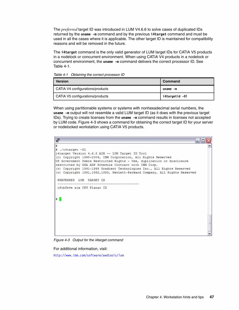
The preferred target ID was introduced in LUM V4.6.6 to solve cases of duplicated IDs returned by the uname -m command and by the previous i4target command and must be used in all the cases where it is applicable. The other target ID is maintained for compatibility reasons and will be removed in the future.
The i4target command is the only valid generator of LUM target IDs for CATIA V5 products in a nodelock or concurrent environment. When using CATIA V4 products in a nodelock or concurrent environment, the uname -m command delivers the correct processor ID. See Table 4-1.
Table 4-1 Obtaining the correct processor ID
When using partitionable systems or systems with nonhexadecimal serial numbers, the uname -m output will not resemble a valid LUM target ID (as it does with the previous target IDs). Trying to create licenses from the uname -m command results in licenses not accepted by LUM code. Figure 4-3 shows a command for obtaining the correct target ID for your server or nodelocked workstation using CATIA V5 products.
Figure 4-3 Output for the i4target command
For additional information, visit:
http://www.ibm.com/software/awdtools/lum
Version Command
CATIA V4 configurations/products uname -m
CATIA V5 configurations/products i4targetid -Ol
Chapter 4. Workstation hints and tips 47

48 IBM IntelliStation POWER 285 Technical Overview and Introduction
Appendix A. Servicing an IBM IntelliStation system
POWER5 processor-based servers can be designated as one of the following types:
� Customer setup (CSU) with customer-installable features (CIF), and customer-replaceable units (CRU)
The IntelliStation POWER 285 is considered CSU.
� Authorized service representative set up, upgraded, and maintained
A number of Web-based resources are available to assist customers and service providers in planning, installing, and maintaining servers.
A
Note: This applies to IBM System p5 and IBM eServer p5 systems in general.
© Copyright IBM Corp. 2005, 2006. All rights reserved. 49
Resource LinkResource Link™ is a customized, Web-based solution, providing access to information for planning, installing, and maintaining IBM servers and associated software. It includes similar information about other selected IBM servers. Access to the site is by IBM registration ID and password that is available free of charge. Resource Link pages can vary by user authorization level and are continually being updated; therefore, the details that you see when accessing Resource Link might not exactly match what is mentioned here.
Resource Link contains links to:
� Education� Planning� Forums� Fixes
Resource Link is available at:
http://www.ibm.com/servers/resourcelink
IBM Systems Hardware Information CenterThe IBM Systems Hardware Information Center is a source for both hardware and software technical information for systems. It has information to help perform a variety of tasks, including:
� Preparing a site to accommodate the hardware for IBM systems.
� Installing the server, console, features and options, and other hardware.
� Installing and using a Hardware Management Console.
� Partitioning the server and installing the operating systems.
� Enabling and managing Capacity on Demand.
� Troubleshooting problems and servicing the server. Included here are component removal and replacement procedures and the Start of Call procedure.
Physical components of a system are generally considered either a customer-replaceable unit (CRU) or a field-replaceable unit (FRU). CRUs are further categorized as either Tier 1 CRUs or Tier 2 CRUs with the following definitions:
– Tier 1 CRU: Very easy to replace
– Tier 2 CRU: More complicated to replace
– FRU: Replaced by the service provider
Removal and replacement procedures can be documented in the information center accompanied by graphics, such as Figure A-1 on page 51, and video clips.
Alternatively, they can take the form of guided procedures using the HMC, for example, by selecting Service Applications → Service Focal Point → Exchange Parts.
50 IBM IntelliStation POWER 285 Technical Overview and Introduction

Figure A-1 Removing a disk drive
The IBM Systems Hardware Information Center is available:
� On the Internet
http://publib.boulder.ibm.com/infocenter/eserver/v1r3s/index.jsp
� On the HMC
Click Information Center and Setup Wizard → Launch the Information Center.
� On CD-ROM
– Shipped with the hardware (English SK3T-8159)
– Also available to order from IBM Publications Center
Note: Part classification, contractual agreements, and implementation in specific geographies all affect how CRUs and FRUs are determined.
Appendix A. Servicing an IBM IntelliStation system 51

52 IBM IntelliStation POWER 285 Technical Overview and Introduction
Related publications
The publications listed in this section are considered particularly suitable for a more detailed discussion of the topics covered in this Redpaper.
IBM RedbooksFor information about ordering these publications, see “How to get IBM Redbooks” on page 54. Note that some of the documents referenced here may be available in softcopy only.
� Advanced POWER Virtualization on IBM System p5, SG24-7940
� Virtual I/O Server Integrated Virtualization Manager, SG24-4061
� Partitioning Implementations for IBM Eserver p5 Servers, SG24-7039
� Advanced POWER Virtualization on IBM Eserver p5 Servers: Architecture and Performance Considerations, SG24-5768
� IBM Eserver pSeries Sizing and Capacity Planning: A Practical Guide, SG24-7071
� IBM Eserver p5 590 and 595 System Handbook, SG24-9119
� IBM Eserver p5 590 and 595 Technical Overview and Introduction, REDP-4024
� IBM Eserver p5 510 Technical Overview and Introduction, REDP-4001
� IBM Eserver p5 520 Technical Overview and Introduction, REDP-9111
� IBM Eserver p5 550 Technical Overview and Introduction, REDP-9113
� IBM Eserver p5 570 Technical Overview and Introduction, REDP-9117
� IBM System p5 505 Express Technical Overview and Introduction, REDP-4079
� IBM System p5 510 and 510Q Technical Overview and Introduction, REDP-4136
� IBM System p5 520 and 520Q Technical Overview and Introduction, REDP-4137
� IBM System p5 550 and 550Q Technical Overview and Introduction, REDP-4138
� IBM System p5 560Q Technical Overview and Introduction, REDP-4139
Other publicationsThese publications are also relevant as further information sources:
� Planning for Partitioned-System Operations, SA38-0626, provides information to planners, system administrators, and operators about how to plan for installing and using a partitioned server. It also discusses some issues associated with the planning and implementing of partitioning.
� System p5, Server p5 Customer service support and troubleshooting, SA38-0538, contains information regarding slot restrictions for adapters that can be used in this system.
� System Unit Safety Information, SA23-2652, contains translations of safety information used throughout the system documentation.
© Copyright IBM Corp. 2005, 2006. All rights reserved. 53

Online resourcesThese Web sites and URLs are also relevant as further information sources:
� SpacePilot, SpaceBall, and SpaceMouse overview
http://www.ibm.com/systems/p/hardware/peripherals/space_controllers.pdf
� AIX 5L operating system maintenance packages downloads
http://www.ibm.com/servers/eserver/support/unixservers/aixfixes.html
� News on new computer technologies
http://www.ibm.com/chips/micronews
� Copper circuitry
http://domino.research.ibm.com/comm/pr.nsf/pages/rsc.copper.html
� IBM Systems Hardware Information Center documentation
http://publib.boulder.ibm.com/infocenter/eserver/v1r3s/index.jsp
� IBM Systems Information Centers
http://publib.boulder.ibm.com/eserver/
� IBM microcode downloads
http://www14.software.ibm.com/webapp/set2/firmware/gjsn
� Support for IBM System p serverst
http://www.ibm.com/servers/eserver/support/unixservers/index.html
� Technical help database for AIX 5L
http://www14.software.ibm.com/webapp/set2/srchBroker/views/srchBroker.jsp?rs=111
� IBMlinkl
http://www.ibmlink.ibm.com
� Microcode Discovery Service
http://www14.software.ibm.com/webapp/set2/mds/fetch?page=mds.html
How to get IBM RedbooksYou can search for, view, or download Redbooks, Redpapers, Hints and Tips, draft publications and Additional materials, as well as order hardcopy Redbooks or CD-ROMs, at this Web site:
ibm.com/redbooks
Help from IBMIBM Support and downloads
ibm.com/support
IBM Global Services
ibm.com/services
54 IBM IntelliStation POWER 285 Technical Overview and Introduction


®
INTERNATIONAL TECHNICALSUPPORTORGANIZATION
BUILDING TECHNICAL INFORMATION BASED ON PRACTICAL EXPERIENCE
IBM Redbooks are developed by the IBM International Technical Support Organization. Experts from IBM, Customers and Partners from around the world create timely technical information based on realistic scenarios. Specific recommendations are provided to help you implement IT solutions more effectively in your environment.
For more information:ibm.com/redbooks
Redpaper
IBM IntelliStation POWER 285Technical Overview and IntroductionDesigned for high-end mechanical computer-aided design
Uses leading-edge IBM POWER5+ processor technology
Delivers a 64-bit CATIA capable environment
This IBM Redpaper is a comprehensive guide covering the IBM IntelliStation POWER 285 workstation. We introduce major hardware offerings and discuss their prominent functions.
Professionals wanting to acquire a better understanding of IBM IntelliStation systems should consider reading this document. The intended audience includes:
� Clients� Sales and marketing professionals� Technical support professionals� IBM Business Partners� Independent software vendors
This document expands the current set of IBM IntelliStation system documentation by providing a desktop reference that offers a detailed technical description of the IntelliStation POWER 285 system.
This publication does not replace the latest marketing materials, product documentation, and tools. It is intended as an additional source of information that, together with existing sources, can be used to enhance your knowledge of IBM server solutions.
Back cover